EP3100941A2 - Véhicule électrique à califourchon - Google Patents
Véhicule électrique à califourchon Download PDFInfo
- Publication number
- EP3100941A2 EP3100941A2 EP16170745.0A EP16170745A EP3100941A2 EP 3100941 A2 EP3100941 A2 EP 3100941A2 EP 16170745 A EP16170745 A EP 16170745A EP 3100941 A2 EP3100941 A2 EP 3100941A2
- Authority
- EP
- European Patent Office
- Prior art keywords
- shaft
- motor
- rear wheel
- gear
- driving
- Prior art date
- Legal status (The legal status is an assumption and is not a legal conclusion. Google has not performed a legal analysis and makes no representation as to the accuracy of the status listed.)
- Granted
Links
Images




Classifications
-
- B—PERFORMING OPERATIONS; TRANSPORTING
- B60—VEHICLES IN GENERAL
- B60K—ARRANGEMENT OR MOUNTING OF PROPULSION UNITS OR OF TRANSMISSIONS IN VEHICLES; ARRANGEMENT OR MOUNTING OF PLURAL DIVERSE PRIME-MOVERS IN VEHICLES; AUXILIARY DRIVES FOR VEHICLES; INSTRUMENTATION OR DASHBOARDS FOR VEHICLES; ARRANGEMENTS IN CONNECTION WITH COOLING, AIR INTAKE, GAS EXHAUST OR FUEL SUPPLY OF PROPULSION UNITS IN VEHICLES
- B60K17/00—Arrangement or mounting of transmissions in vehicles
- B60K17/02—Arrangement or mounting of transmissions in vehicles characterised by arrangement, location, or kind of clutch
-
- B—PERFORMING OPERATIONS; TRANSPORTING
- B62—LAND VEHICLES FOR TRAVELLING OTHERWISE THAN ON RAILS
- B62M—RIDER PROPULSION OF WHEELED VEHICLES OR SLEDGES; POWERED PROPULSION OF SLEDGES OR SINGLE-TRACK CYCLES; TRANSMISSIONS SPECIALLY ADAPTED FOR SUCH VEHICLES
- B62M7/00—Motorcycles characterised by position of motor or engine
- B62M7/12—Motorcycles characterised by position of motor or engine with the engine beside or within the driven wheel
-
- B—PERFORMING OPERATIONS; TRANSPORTING
- B60—VEHICLES IN GENERAL
- B60K—ARRANGEMENT OR MOUNTING OF PROPULSION UNITS OR OF TRANSMISSIONS IN VEHICLES; ARRANGEMENT OR MOUNTING OF PLURAL DIVERSE PRIME-MOVERS IN VEHICLES; AUXILIARY DRIVES FOR VEHICLES; INSTRUMENTATION OR DASHBOARDS FOR VEHICLES; ARRANGEMENTS IN CONNECTION WITH COOLING, AIR INTAKE, GAS EXHAUST OR FUEL SUPPLY OF PROPULSION UNITS IN VEHICLES
- B60K17/00—Arrangement or mounting of transmissions in vehicles
- B60K17/04—Arrangement or mounting of transmissions in vehicles characterised by arrangement, location or kind of gearing
- B60K17/14—Arrangement or mounting of transmissions in vehicles characterised by arrangement, location or kind of gearing the motor of fluid or electric gearing being disposed in, or adjacent to, traction wheel
- B60K17/145—Arrangement or mounting of transmissions in vehicles characterised by arrangement, location or kind of gearing the motor of fluid or electric gearing being disposed in, or adjacent to, traction wheel the electric gearing being disposed in or adjacent to traction wheel
-
- B—PERFORMING OPERATIONS; TRANSPORTING
- B60—VEHICLES IN GENERAL
- B60K—ARRANGEMENT OR MOUNTING OF PROPULSION UNITS OR OF TRANSMISSIONS IN VEHICLES; ARRANGEMENT OR MOUNTING OF PLURAL DIVERSE PRIME-MOVERS IN VEHICLES; AUXILIARY DRIVES FOR VEHICLES; INSTRUMENTATION OR DASHBOARDS FOR VEHICLES; ARRANGEMENTS IN CONNECTION WITH COOLING, AIR INTAKE, GAS EXHAUST OR FUEL SUPPLY OF PROPULSION UNITS IN VEHICLES
- B60K17/00—Arrangement or mounting of transmissions in vehicles
- B60K17/22—Arrangement or mounting of transmissions in vehicles characterised by arrangement, location, or type of main drive shafting, e.g. cardan shaft
- B60K17/24—Arrangement of mountings for shafting
-
- B—PERFORMING OPERATIONS; TRANSPORTING
- B62—LAND VEHICLES FOR TRAVELLING OTHERWISE THAN ON RAILS
- B62K—CYCLES; CYCLE FRAMES; CYCLE STEERING DEVICES; RIDER-OPERATED TERMINAL CONTROLS SPECIALLY ADAPTED FOR CYCLES; CYCLE AXLE SUSPENSIONS; CYCLE SIDECARS, FORECARS, OR THE LIKE
- B62K11/00—Motorcycles, engine-assisted cycles or motor scooters with one or two wheels
-
- B—PERFORMING OPERATIONS; TRANSPORTING
- B62—LAND VEHICLES FOR TRAVELLING OTHERWISE THAN ON RAILS
- B62M—RIDER PROPULSION OF WHEELED VEHICLES OR SLEDGES; POWERED PROPULSION OF SLEDGES OR SINGLE-TRACK CYCLES; TRANSMISSIONS SPECIALLY ADAPTED FOR SUCH VEHICLES
- B62M11/00—Transmissions characterised by the use of interengaging toothed wheels or frictionally-engaging wheels
- B62M11/02—Transmissions characterised by the use of interengaging toothed wheels or frictionally-engaging wheels of unchangeable ratio
-
- B—PERFORMING OPERATIONS; TRANSPORTING
- B62—LAND VEHICLES FOR TRAVELLING OTHERWISE THAN ON RAILS
- B62M—RIDER PROPULSION OF WHEELED VEHICLES OR SLEDGES; POWERED PROPULSION OF SLEDGES OR SINGLE-TRACK CYCLES; TRANSMISSIONS SPECIALLY ADAPTED FOR SUCH VEHICLES
- B62M21/00—Transmissions characterised by use of resilient elements therein
-
- B—PERFORMING OPERATIONS; TRANSPORTING
- B62—LAND VEHICLES FOR TRAVELLING OTHERWISE THAN ON RAILS
- B62K—CYCLES; CYCLE FRAMES; CYCLE STEERING DEVICES; RIDER-OPERATED TERMINAL CONTROLS SPECIALLY ADAPTED FOR CYCLES; CYCLE AXLE SUSPENSIONS; CYCLE SIDECARS, FORECARS, OR THE LIKE
- B62K2204/00—Adaptations for driving cycles by electric motor
-
- F—MECHANICAL ENGINEERING; LIGHTING; HEATING; WEAPONS; BLASTING
- F16—ENGINEERING ELEMENTS AND UNITS; GENERAL MEASURES FOR PRODUCING AND MAINTAINING EFFECTIVE FUNCTIONING OF MACHINES OR INSTALLATIONS; THERMAL INSULATION IN GENERAL
- F16H—GEARING
- F16H1/00—Toothed gearings for conveying rotary motion
- F16H1/02—Toothed gearings for conveying rotary motion without gears having orbital motion
- F16H1/04—Toothed gearings for conveying rotary motion without gears having orbital motion involving only two intermeshing members
- F16H1/06—Toothed gearings for conveying rotary motion without gears having orbital motion involving only two intermeshing members with parallel axes
Definitions
- the present invention relates to a vehicle, and in particular, though not exclusively, to a straddled electric vehicle. More particularly, the present invention relates to an off-road straddled electric vehicle.
- Straddled electric vehicles include electric motorcycles, for example.
- An electric motorcycle is disclosed in WO 2012/90245 (KAWASAKI ), for example.
- driving power from the motor is transmitted to a rear wheel shaft via a power transmission mechanism to rotate a rear wheel.
- An off-road straddled electric vehicle often travels on poor or bad roads. As such, while the vehicle is travelling, irregularities on the road may cause the vehicle to bounce or jump such that a rear wheel leaves the ground. The rear wheel is under no-load conditions after a rear wheel leaves the ground due to a bounce or jump until the rear wheel lands on the ground, and is then under a load again. That is, the magnitude of the load on the rear wheel dramatically changes. As the magnitude of the load on the rear wheel changes dramatically, an overcurrent flows in the motor. Thus, there may be a moment at which, even when the rider operates the throttle grip, the associated control may not be transmitted to the motor.
- an object of at least one embodiment of at least one aspect of the present invention is to provide a straddled electric vehicle that seeks to prevent overcurrent flowing when the load on the driving wheel dramatically changes.
- a vehicle such as a straddled vehicle or an electric vehicle, and particularly such as a straddled electric vehicle.
- the vehicle may receive or be constructed to receive driving power from a motor to move or travel.
- the vehicle may comprise one or more of: a motor, a driving wheel, and a power transmission mechanism.
- the power transmission mechanism may have a plurality of shafts, e.g. for transmitting the driving power from the motor to the driving wheel.
- the power transmission mechanism may comprise: a first shaft which may have a spline gear or groove on a shaft surface thereof.
- the spline gear or groove may be inclined relative to an axial direction.
- the power transmission mechanism may comprise a rotating member which may be attached to the first shaft and which may have a spline gear or groove engageable with the spline groove on the first shaft.
- the rotating member may be capable of exchanging a rotating force with the first shaft.
- the power transmission mechanism may comprise an elastic member which may be capable of biasing one of the rotating member attached to the first shaft and the first shaft toward an/one axial direction.
- the spline gears or grooves may be inclined so as to move the rotating member or the first shaft toward an/the other opposite/axial direction when the driving wheel is rotating in a direction causing the straddled electric vehicle to advance and the rotating member or the first shaft works or acts to maintain a speed of rotation of the driving wheel as the speed of rotation is decreasing.
- the first shaft may engage the rotating member by means of the spline gears or grooves.
- the spline gears or grooves may be inclined relative to the/an axial direction, e.g. such that the rotating force of the rotating member may act in a direction inclined relative to the first shaft.
- part of the rotating force of the rotating member may be transmitted to the shaft as a force causing the rotating member to move in an axial direction relative to the first shaft, and the remaining rotating force may be transmitted to the shaft as a force causing the first shaft to rotate about its axis.
- the power transmission mechanism may further include an elastic member for biasing the rotating member or first shaft in one axial direction.
- an elastic member for biasing the rotating member or first shaft in one axial direction.
- part of the rotating force of the rotating member may be transmitted to the shaft as a force causing the rotating member to move in an axial direction relative to the first shaft.
- the elastic member may be pushed by the rotating member or first shaft and thereby increases an elastic force thereof.
- part of the rotating force of the rotating member i.e. rotating force acting in an axial direction
- the rotating force of the rotating member may be transmitted as a force causing the first shaft to rotate about the axis.
- the magnitude of the load on the driving wheel may decrease such that the driving wheel is substantially under no-load conditions, which increases the speed of rotation of the driving wheel from that encountered during normal travelling. Further, if the magnitude of the load on the driving wheel decreases such that the wheel may be substantially under no-load conditions, the rotating member or first shaft may be caused by the elastic force of the elastic member to move in one direction.
- the driving wheel may stop rotating temporarily.
- the first shaft or rotating member may move in the axial direction that is opposite the one direction due to the effects of the spline grooves, and continue to rotate while squeezing the elastic member. That is, there may be a rotation phase difference between the rotation of the rotating member and that of the first shaft.
- there may be a rotation phase difference between the rotation of the rotating member and that of the first shaft there may be a time lag between the time at which the effect of the load applied to the driving wheel (that is, temporary halt of the first shaft) occurs and the time at which this effect affects the driving of the motor (that is, rotation of the rotating member). This may act to prevent an overcurrent flowing in the motor due to a load suddenly applied to the driving wheel.
- the rotating member or the first shaft of the straddled electric vehicle of the present invention may move in the other axial direction while resisting an elastic force of the elastic member.
- the elastic member may apply essentially no elastic force to the rotating member or the first shaft.
- the elastic member when the rotating member or first shaft may not be transmitting driving power to the driving wheel, the elastic member may apply essentially no elastic force to the rotating member or first shaft.
- the rotating member or first shaft of the straddled electric vehicle transitions to such a state, it may be immediately possible to tolerate a phase difference between the rotation of the rotating member and that of the first shaft. Problems may occur if the vehicle is not in the above arrangement, i.e. if the vehicle is constructed such that, when the rotating member or first shaft is not transmitting driving power to the driving wheel, the elastic member exerts a certain elastic force to the rotating member or first shaft.
- the rotating member or first shaft not transmitting driving power to the driving wheel means not only the motor not rotating, but also the driving wheel being rotated by a force other than driving power transmitted from the motor when the driving wheel is off the ground or the vehicle is travelling on a downward slope, for example.
- the rotating member may move in the other axial direction.
- the rotating member may be movable, which may prevent the bearing structure from becoming complicated compared with implementations where the first shaft moves. Further, since out of the rotating member and first shaft, the rotating member may be movable, the object pushed by the elastic member via an elastic force thereof may be the rotating member. Since the rotating member may have a diameter larger than that of the first shaft, the structure used by the elastic member to apply an elastic force to the object may be prevented from becoming complicated.
- the elastic member of the straddled electric vehicle of the present invention may be a disc spring for applying an elastic force pushing the rotating member in the one direction.
- the spring may have a large elastic force even if elastic deformation may be small. Since driving power which may have a large torque may be transmitted to the driving shaft by the power transmission mechanism, a disc spring with a large elastic modulus may be suitable for the elastic member.
- the plurality of shafts of the straddled electric vehicle of the present invention may comprise or include a motor shaft capable of being rotated by the driving power of the motor and a driving shaft capable of rotating the driving wheel, wherein the first shaft may be the driving shaft.
- the speed of rotation may decrease when driving power is transmitted from the motor shaft to the driving shaft. In other words, speed increases as it goes toward the motor shaft from the driving shaft.
- the rotating member or first shaft may be moved due to the inclined spline grooves in an axial direction by a small distance, it may be possible to efficiently reduce effects on the motor. That is, the size thereof as measured in the vehicle width direction can be reduced.
- the plurality of shafts of the straddled electric vehicle of the present invention may further comprise an intermediate shaft capable of transmitting the driving power transmitted from the motor shaft to the driving shaft.
- the rotating member engaging the driving shaft may be a gear coaxial with the driving shaft.
- the driving power transmission mechanism may comprise an intermediate shaft between the motor shaft and driving shaft.
- the inclined spline grooves may be located distant from the motor shaft.
- the inertia of the rotating member rotating together with the motor shaft may increase. This may reduce effects on the motor more efficiently.
- the spline grooves provided on the driving shaft and the rotating member of the straddled electric vehicle of the present invention may be inclined relative to the axial direction by 40 to 50 degrees.
- part of the driving power transmitted to the driving shaft from the rotating member can be efficiently directed to an axial direction of the driving shaft.
- the plurality of shafts of the straddled electric vehicle of the present invention may comprise:
- the plurality of shafts of the straddled electric vehicle of the present invention may comprise:
- the rotating member engaging the motor shaft may be a member including a rotor of the motor.
- the elastic member of the straddled electric vehicle may bias the motor shaft toward the one direction.
- the vehicle may be constructed to receive driving power from a motor to move or travel.
- the motor may advantageously and most preferably comprise an electric motor.
- An off-road straddled electric vehicle often travels on poor or bad roads. As such, while the vehicle is travelling, irregularities on the road may cause the vehicle to jump such that the rear wheel leaves the ground. When the rider does not intend the rear wheel to leave the ground, the rear wheel may leave the ground with the throttle grip fully turned. In this case, driving power from the motor continues to be transmitted to the rear wheel shaft.
- the present inventors investigated what structure would not transmit sudden changes in the load on the rear wheel to the motor in a direct manner.
- a straddled electric vehicle according to a first embodiment of the present invention will be described below with reference to Figures 1 to 5 .
- the present embodiment will be described in connection with an electric motorcycle as an example of the straddled electric vehicle.
- the same or corresponding parts in the drawings are labeled with the same characters and their description will not be repeated.
- Figure 1 is a left side view of an electric motorcycle 10 according to a first embodiment of the present invention.
- forward/front, rear(ward), left and right means such directions as perceived by a rider sitting on the seat 30 of the electric motorcycle 10.
- arrow F indicates the forward direction with respect to the electric motorcycle 10
- arrow U indicates the upward direction with respect to the electric motorcycle 10 (the same applies to Figure 2 below).
- the electric motorcycle 10 comprises a front wheel 11 F, a rear wheel 11 R, a vehicle body frame 12, handlebars 18, a front fork 19, a battery unit 20, a drive unit 22, a rear arm 24, a rear cushion 26, a vehicle body cover 28, and a seat 30.
- the front wheel 11 F comprises a wheel body 27F and a front wheel tire (tyre) 29F.
- the rear wheel 11 R comprises a wheel body 27R and a rear wheel tire 29R.
- the front fork 19 supports the front wheel 11F such that it is rotatable. Operating the handlebars 18 changes the direction of the front wheel 11 F.
- the vehicle body frame 12 supports the rear (swing) arm 24 such that it can swing in the top/bottom up/down direction.
- the rear arm 24 supports the rear wheel 11 R such that it is rotatable.
- the rear cushion suspension/shock absorber 26 is located between the rear arm 24 and vehicle body frame 12.
- the drive unit 22 is provided on the rear arm 24.
- the drive unit 22 is located in the vicinity of the rear wheel 11R. That is, the electric motorcycle 10 has a so-called unit-swing driving structure.
- the vehicle body frame 12 supports the battery unit 20.
- the battery unit 20 includes a battery (not shown), a battery case 62 containing the battery, and a controller 68. Electric power stored in the battery is supplied to the drive unit 22 via the controller 68. This drives the drive unit 22.
- the drive unit 22 includes a motor 32. Driving power from the drive unit 22 is transmitted to the rear wheel 11 R. This rotates the rear wheel 11 R.
- the vehicle body frame 12 supports the vehicle body cover 28.
- the vehicle body cover 28 covers part of the vehicle body frame 12 in a side view of the vehicle.
- the vehicle body frame 12 supports the seat 30.
- the seat 30 is located above the vehicle body frame 12.
- Figure 2 is a left side view of the drive unit 22.
- Figure 3 is a cross-sectional view of the drive unit 22 taken along line III-III of Figure 2 .
- arrow R indicates the right direction with respect to the electric motorcycle 10
- arrow L indicates the left direction with respect to the electric motorcycle 10 (the same applies to Figures 4 to 7 below).
- the drive unit 22 will be described with reference to Figures 2 and 3 .
- the drive unit 22 includes the motor 32 and a power transmission mechanism 40.
- the motor 32 comprises a motor shaft 33, a rotor 34, a stator 35, a bearing 36, a bearing 37, a first motor case portion 38, and a second motor case portion 39.
- the motor shaft 33 is positioned with a shaft center thereof coincident or consistent with an axis L1 extending in the left/right direction.
- the bearing 36 is located between the motor shaft 33 and first motor case portion 38.
- the bearing 37 is located between the motor shaft 33 and second motor case portion 39.
- the motor shaft 33 is supported on the first and second motor case portions 38 and 39 by means of the bearings 36 and 37, and is rotatable about the axis L1. As the motor 32 rotates, the motor shaft 33 rotates in the forward direction.
- the rotor 34 is cylindrical in shape.
- the rotor 34 is positioned around the motor shaft 33. Similar to the motor shaft 33, the rotor 34 is positioned with its shaft center consistent with the axis L1.
- the rotor 34 is rotatable together with the motor shaft 33 about the axis L1.
- the stator 35 is cylindrical in shape.
- the stator 35 is positioned around the rotor 34. Similar to the motor shaft 33 and rotor 34, the stator 35 is positioned with a shaft center thereof coincident or consistent with the axis L1.
- the stator 35 is fixed to the second motor case portion 39.
- the stator 35 comprises a stator body and a plurality of cores, for example.
- the first motor case portion 38 is generally circular in shape in side view.
- the second motor case portion 39 is generally cylindrical in shape with a height thereof oriented in the left/right direction.
- the second motor case portion 39 has an open left portion.
- the first motor case portion 38 is fitted into the opening of the second motor case portion 39.
- the second motor case portion 39 has a right portion that is circular in side view.
- the circular right portion of the second motor case portion 39 has a hole at a center thereof.
- the motor shaft 33 extends through the hole in the right portion of the second motor case portion 39.
- in a space defined by the second motor case portion 39 and the first motor case portion 38 are positioned a left portion of the motor shaft 33, the rotor 34, the stator 35 and the bearings 36 and 37.
- the power transmission mechanism 40 comprises the motor shaft 33 of the motor 32, an intermediate shaft 41, a rear wheel shaft (or driving shaft) 42, a first gear 43, and a second gear 44.
- the power transmission mechanism 40 receives driving power produced by the rotation of the motor 32 and transmits such to the rear wheel shaft 42 via the intermediate shaft 41.
- Driving power produced by the rotation of the motor 32 is transmitted to the rear wheel shaft 42 with torque thereof amplified.
- the motor shaft 33 constitutes a part of the motor 32. As shown in Figure 3 , the left portion of the motor shaft 33 is located in the space defined by the first and second motor case portions 38 and 39 of the motor 32. The motor shaft 33 extends through the second motor case portion 39. The motor shaft 33 has a right portion protruding toward the right of the motor 32. A plurality of gear grooves 331 extending parallel to each other are provided on the surface of the right portion of the motor shaft 33. The gear grooves 331 extend parallel to the axis L1.
- the intermediate shaft 41 is positioned with a shaft center thereof coincident or consistent with an axis L2 extending in the left/right direction. As shown in Figure 3 , the intermediate shaft 41 is supported on the housing 49 by means of bearings 45 and 46. The bearings 45 and 46 make the intermediate shaft 41 rotatable about the axis L2. A plurality of gear grooves 411 extending parallel to each other are provided on a portion of the surface of the intermediate shaft 41. The gear grooves 411 extend parallel to the axis L2.
- the first gear 43 is attached to the intermediate shaft 41.
- the first gear 43 is annular in shape.
- the inner periphery 431 of the first gear 43 is fixed to the surface of the intermediate shaft 41.
- Gear grooves may be provided on the inner periphery 431 of the first gear 43 and spline grooves may be provided on the surface of the intermediate shaft 41, in which case the gear grooves may engage the spline grooves to fix the first gear 43 to the intermediate shaft 41.
- a plurality of gear grooves 432 extending parallel to each other are provided on the outer periphery of the first gear 43.
- the gear grooves 432 extend parallel to the axis L2.
- the gear grooves 432 engage the gear grooves 331 on the surface of the motor shaft 33.
- the rear wheel shaft 42 is positioned with a shaft center thereof coincident or consistent with an axis L3 extending in the left/right direction.
- the rear wheel shaft 42 is supported on the housing 49 by means of bearings 47 and 48.
- the bearings 47 and 48 make the rear wheel shaft 42 rotatable about the axis L3.
- a plurality of spline grooves 421 extending parallel to each other are provided on a portion of the surface of the rear wheel shaft 42.
- the spline grooves 421 are inclined relative to the axis L3.
- Figure 3 shows the area where the spline grooves 421 are coupled to the second gear 44 as a line parallel to the axis L3 (such portions are shown in Figures 4 and 5 in a similar manner).
- the wheel body 27R shown in Figure 3 is fixed to the rear wheel shaft 42 (the fixed portions are not shown).
- the wheel body 27R is positioned with a shaft center coincident or consistent with the axis L3.
- the rear wheel shaft 42 is fixed to the center of the wheel body 27R.
- the wheel body 27R can rotate in synchronization with the rotation of the rear wheel shaft 42. That is, the rear wheel 11 R can rotate in synchronization with the rotation of the rear wheel shaft 42.
- the second gear 44 is attached to the rear wheel shaft 42.
- the second gear 44 is annular in shape.
- a plurality of spline grooves 441 extending parallel to each other are provided on the inner periphery of the second gear 44.
- the spline grooves 441 are inclined relative to the axis L3. As discussed further below, the spline grooves 441 engage the spline grooves 421 on the rear wheel shaft 42.
- a plurality of gear grooves 442 extending parallel to each other are provided on the outer periphery of the second gear 44.
- the gear grooves 442 extend parallel to the axis L3.
- the gear grooves 442 engage the gear grooves 411 on the surface of the intermediate shaft 41.
- a mechanism for tolerating a rotation phase difference, 50 is provided around the location where the spline grooves 421 on the rear wheel shaft 42 engage the spline grooves 441 on the second gear 44.
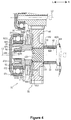
- Figure 4 is an enlarged view of the mechanism 50 for tolerating a rotation phase difference of Figure 3 .
- Figure 4 shows a first state S1 of the mechanism 50 for tolerating a rotation phase difference.
- the mechanism 50 for tolerating a rotation phase difference is made up of the rear wheel shaft 42, the second gear 44, a member 52, a member 53, a member 54, and an elastic member 51.
- Figure 5 shows a second state S2 of the mechanism 50 for tolerating a rotation phase difference.
- the mechanism 50 for tolerating a rotation phase difference can be switched between the first state S1 shown in Figure 4 and the second state S2 shown in Figure 5 depending on the travel condition of the elastic motorcycle 10.
- a portion of the rear wheel shaft 42 that comprises a left end surface 426 thereof constitutes a first portion 427.
- a portion of the rear wheel shaft 42 that is connected to the first portion 427 constitutes a second portion 428, while a portion thereof that is connected to the second portion 428 constitutes a third portion 429.
- the borders between the first, second and third portions 427, 428 and 429 are shown by chain lines.
- the diameter of a cross-section of the first portion 427 perpendicular to the axis L3 is smaller than the diameter of the second portion 428.
- the diameter of a cross-section of the second portion 428 perpendicular to the axis L3 is smaller than the diameter of the third portion 429.
- the annular member 52 is attached to the rear wheel shaft 42 and is located to the left of the second gear 44.
- the annular member 53 is attached to the rear wheel shaft 42 and is located to the right of the second gear 44.
- the annular member 54 is attached to the rear wheel shaft 42 and is located to the left of the member 52.
- the members 52, 53 and 54 are positioned with shaft centers thereof coincident or consistent with the axis L3.
- the members 52, 53 and 54 rotate together with the rear wheel shaft 42 about the axis L3.
- the member 52 is made up of a left portion 521, an intermediate portion 522 and a right portion 523.
- the left, intermediate and right portions 521, 522 and 523 are integrally formed.
- the left, intermediate and right portions 521, 522 and 523 are annular in shape.
- the inner peripheries of the intermediate and right portions 522 and 523 of the member 52 are fixed to the rear wheel shaft 42.
- the member 52 is fixed to the rear wheel shaft 42 as it is tightened up by the member 54 by clearance fitting.
- the left portion 521 of the member 52 constitutes a left portion of the member 52.
- the outer periphery 5211 of the left portion 521 is fixed to the bearing 47.
- the bearing 47 includes an outer ring 471 and an inner ring 472.
- the outer periphery 5211 of the left portion 521 is fixed to the inner periphery 4721 of the inner ring 472 of the bearing 47.
- the left portion 521 is fixed to the inner ring 472 by clearance fitting.
- the right portion 523 of the member 52 constitutes a right portion of the member 52.
- the right side 5231 of the right portion 523 is in contact with the step 4281 on the rear wheel shaft 42.
- the elastic member 51 is attached to the outer periphery of the right portion 523 of the member 52.
- the elastic member 51 will be described in detail further below.
- the intermediate portion 522 of the member 52 is a structure between the left and right portions 521 and 523.
- the outer diameter of a cross section of the intermediate portion 522 perpendicular to the axis L3 is larger than the outer diameter of a cross section of the left portion 521.
- the inner diameter of a cross-section of the intermediate portion 522 perpendicular to the axis L3 is smaller than the inner diameter of a cross-section of the left portion 521.
- the outer diameter of a cross-section of the intermediate portion 522 perpendicular to the axis L3 is larger than the outer diameter of a cross-section of the right portion 523.
- the inner periphery 542 of the member 54 is fixed to the surface of the rear wheel shaft 42.
- the member 54 is fixed to the rear wheel shaft 42 by means of a thread.
- the right side 541 of the member 54 is in contact with the left side 5223 of the intermediate portion 522.
- the member 52 is sandwiched between the step 4281 of the rear wheel shaft 42 and the member 54, thereby restricting its movement in the direction of the axis L3.
- the member 53 is located to the right of the second gear 44.
- the member 53 is fixed to the rear wheel shaft 42 by means of spline grooves.
- the right side 532 of the member 53 is in contact with the step 4291 of the rear wheel shaft 42.
- the distance between the right side 5231 of the right portion 523 of the member 52 and the left side 531 of the member 53 is larger than the size of the second gear 44 as measured in the direction of the axis L3.
- the second gear 44 is movable in the direction of the axis L3 between the members 52 and 53.
- the elastic member 51 is located on the outer periphery of the right portion 523 of the member 52.
- the elastic member 51 is annular in shape.
- the elastic member 51 can be extended and contracted in the direction of the axis L3.
- the elastic member 51 may be a disc spring, for example.
- the left end 511 of the elastic member 51 is in contact with the right side 5222 of the intermediate portion 522 of the member 52.
- the right end 512 of the elastic member 51 is in contact with the left side 448 of the second gear 44.
- the left end 511 of the elastic member 51 may be fixed to the right side 5222 of the intermediate portion 522 by an adhesive, for example.
- the right end 512 of the elastic member 51 may be fixed to the left side 448 of the second gear 44 by an adhesive, for example.
- first state S1 When no external force is applied to the elastic member 51, the right side 449 of the second gear 44 is in contact with the left side 531 of the member 53, as shown in Figure 4 .
- first state S1 When a force toward the left is applied by the second gear 44 to the elastic member 51, the elastic member 51 is contracted such that the left side 443 of the second gear 44 is close to the right side 5231 of the right side 523 of the member 52.
- second state S2 In the second state S2, the component of the rotating force from the second gear 44 that is in the direction of the axis L3 and the elastic force of the elastic member 51 are opposite to each other and have an equal magnitude, i.e. they are in balance.
- Figure 5 shows the left side 443 of the second gear 44 and the right side 5231 of the right portion 523 as in contact with each other.
- a plurality of spline grooves 421 are provided on the portions of the surface of the second portion 428 of the rear wheel shaft 42 that are located between the right side 5231 of the right portion 523 of the member 52 and the left side 531 of the member 53.
- the spline grooves 421 are inclined at an angle relative to the axis L3.
- the inclination angle of the spline grooves 421 relative to the shaft L3 may be in the range of 40 to 50 degrees, for example.
- the spline grooves 421 are disposed such that their left ends are located forward of their right ends.
- a plurality of spline grooves 441 are provided on the inner periphery of the second gear 44.
- the spline grooves 441 are inclined at the same angle relative to the axis L3 as the spline grooves 421 on the rear wheel axis 42.
- first state S1 When the electric motorcycle 10 is standing still, the elastic member 51 is located at the rightmost position, as shown in Figure 4 . This state will be referred to as first state S1.
- the rotating force of the second gear 44 is transmitted to the rear wheel shaft 42 via the mechanism 50 for tolerating a rotation phase difference.
- the rear wheel shaft 42 and second gear 44 engage each other by means of the spline grooves 421 and 441 inclined relative to the axis L3 such that the rotating force of the second gear 44 is applied to the rear wheel shaft 42 in a direction inclined relative to the shaft.
- a part of the rotating force of the second gear 44 is transmitted to the rear wheel shaft 42 as a force causing the second gear 44 to move in the direction of the axis L3 toward the left, and the remaining rotating force is transmitted thereto as a force causing the rear wheel shaft 42 to rotate about the axis L3.
- the power transmission mechanism 40 includes the elastic member 51 which produces an elastic force pushing the second gear 44 toward the right.
- a part of the rotating force of the second gear 44 is transmitted to the shaft as a force causing the second gear 44 to move in the direction of the axis L3 toward the left such that the elastic member 51 is pushed by the second gear 44 toward the left, thereby increasing its elastic force.
- part of the rotating force of the second gear 44 i.e. rotating force acting in an axial direction
- the elastic force of the elastic member 51 are eventually brought into balance such that the second gear 44 and rear wheel shaft 42 do not move any more relative to each other in an axial direction.
- the state at this moment is the second state S2 shown in Figure 5 .
- the rotating force of the second gear 44 is transmitted as a force causing the rear wheel shaft 42 to rotate about the axis L3.
- the second gear 44 and elastic member 51 are in the second state S2 shown in Figure 5 , as discussed above. It is now assumed that, when the electric motorcycle 10 is travelling, irregularities on the ground, for example, have caused the rear wheel 11 R to leave the ground. When the rear wheel 11 R leaves the ground, the friction force received by the rear wheel 11R from the ground during travelling becomes zero. This causes the rear wheel 11 R to slip. Further, when the friction force received by the rear wheel 11 R from the ground becomes zero, the second gear 44 only needs a smaller force to rotate the rear wheel shaft 42, and its force pushing the elastic member 51 decreases to that extent. Then, the elastic force of the elastic member 51 advantageously causes the second gear 44 to move toward the right. That is, the second gear 44 beneficially transitions from the second state S2 to the first state S1.
- the power transmission mechanism 40 of the drive unit 22 and the mechanism 50 for tolerating a rotation phase difference operate in the same manner as during normal travelling.
- an overcurrent may flow in the rotor of the motor.
- the motor may be temporarily uncontrollable.
- the power transmission mechanism 40 operates in the following manner when the electric motorcycle 10 hits an obstacle, for example, and the rear wheel 11R leaves the ground: when the rear wheel 11 R leaves the ground and then the rear wheel 11 R lands on the ground once again and the rear wheel shaft 42 stops temporarily, there is a time lag between the time at which the effect of the load applied to the rear wheel 11 R (that is, temporary halt of the rear wheel shaft 42) occurs and the time at which this effect affects the driving of the motor 32 (that is, rotation of the second gear 44).
- the power transmission mechanism 40 in the present embodiment uses the mechanism 50 for tolerating a rotation phase difference described above to prevent overcurrent in the motor 32.
- the mechanism 50 for tolerating a rotation phase difference is located in the area where the second gear 44 and rear wheel shaft 42 exchange rotating forces.
- torque increases as it goes from the motor shaft 33 toward the rear wheel shaft 42.
- the large torque of rotating forces exchanged by the second gear 44 and rear wheel shaft 42 makes it possible to reduce the distance by which the second gear 44 moves in the direction of the axis L3. This reduces the size of the drive unit 22 as measured in the left/right direction.
- an intermediate shaft 41 is provided between the motor shaft 33 and rear wheel shaft 42.
- the torque of driving power increases as the driving power is transmitted from the motor shaft 33 to the intermediate shaft 41, and the torque further increases as the driving power is transmitted from the intermediate shaft 41 to the rear wheel shaft 42, thereby increasing the efficiency with which torque is amplified. This makes it possible to reduce the size of the drive unit 22 as measured in the left/right direction.
- the elastic member 51 is a disc spring. Due to the large elastic modulus of a disc spring, the member has a large elastic force even if elastic deformation is small. Thus, a disc spring with a large elastic modulus is suitable in the rear wheel shaft 42 which exchanges driving power with a large torque.
- the spline grooves 421 on the rear wheel shaft 42 and the spline grooves 441 on the second gear 44 are inclined, for example, at an angle ranging from 40 to 50 degrees; thus, part of the driving power transmitted to the rear wheel shaft 42 from the second gear 44 can be efficiently directed to an axial direction of the rear wheel shaft 42.
- all of the rotating force of the second gear 44 may be transmitted as a force for rotating the rear wheel shaft 42 about the axis L3; even then, the rotating force is transmitted from the second gear 44 to the rear wheel shaft 42 with good transmission efficiency since the spline grooves 421 and 441 are inclined at an angle ranging from 40 to 50 degrees.
- the above embodiment describes that the right side 449 of the second gear 44 is in contact with the left side 531 of the member 53 when the mechanism is in the first state S1 shown in Figure 4 ; however, the right side 449 of the second gear 44 need not be in contact with the left side 531 of the member 53. If the position of the second gear 44 in the first state S1 is to the right of the position thereof in the second state S2, it is possible to ensure that the state in which the elastic member 51 is at its natural length is represented by the first state S1 even if the right side 449 of the second gear 44 is not in contact with the left side 531 of the member 53.
- the above embodiment describes that the left side 443 of the second gear 44 is in contact with the right side 5231 of the right portion 523 of the member 52 when the mechanism is in the second state S2 shown in Figure 5 ; however, the left side 443 of the second gear 44 need not be in contact with the right side 5231 of the right portion 523. If the position of the second gear 44 in the second state S2 is to the left of the position thereof in the first state S1, it is possible to ensure that the state in which the elastic force of the elastic member 51 is in balance with part of the rotating force of the second gear 44 (i.e. component in the direction of the axis L3) is represented by the second state S2.
- the elastic member 51 is a disc spring; however, the type of the elastic member 51 is not limited to disc spring.
- the elastic member 51 may be a coil spring.
- the elastic member 51 is preferably a disc spring to minimize the size of the drive unit 22 as measured in the left/right direction.
- the overall construction of the electric motorcycle of the second embodiment is the same as that of the electric motorcycle 10 of the first embodiment.
- a drive unit 22A has a different construction from that of the drive unit 22 of the first embodiment.
- Figure 6 shows the drive unit 22A of the second embodiment. Similar to the drive unit 22 of the first embodiment, the drive unit 22A comprises a motor 32 and a power transmission mechanism 40A.
- the motor 32 has the same construction as in the first embodiment.
- the power transmission mechanism 40A comprises a motor shaft 33 of the motor 32, an intermediate shaft 41A, a rear wheel shaft (driving shaft) 42A, a first gear 43A, and a second gear 44A.
- Figure 6 shows a cross-section of the drive unit 22A that includes an axis L1 which represents the shaft center of the motor shaft 33, an axis L2 which represents the shaft center of the intermediate shaft 41 A and an axial L3 which represents the shaft center of the rear wheel shaft 42A.
- a mechanism 50A for tolerating a rotation phase difference in the second embodiment is constructed on the intermediate shaft 41A.
- the mechanism 50A for tolerating a rotation phase difference will be described below.
- the mechanism 50A for tolerating a rotation phase difference is made up of the intermediate shaft 41A, the first gear 43Aand an elastic member 51A.
- Figure 6 shows the mechanism 50A for tolerating a rotation phase difference in a state found when the motor 32 is not rotating.
- gear grooves 411 A are provided on a left portion of the intermediate shaft 41A.
- the gear grooves 411A engage gear grooves 442A provided on the outer periphery of the second gear 44A.
- Spline grooves 412A are provided on the intermediate shaft 41A and located to the right of the gear grooves 411 A.
- the spline grooves 412A will be described further below.
- Figure 6 shows the area where the spline grooves 421A are coupled to the first gear 43A as a line parallel to the axis L2.
- the first gear 43A has a plurality of gear grooves 431A on an outer periphery thereof. As shown in Figure 6 , the gear grooves 431A engage the gear grooves 331 on the motor shaft 33.
- a plurality of gear grooves 431A are provided on the inner periphery of the first gear 43A.
- the gear grooves 431A engage the spline grooves 412A on the intermediate shaft 41A.
- the gear grooves 431A will be described further below.
- the elastic member 51A is disposed around the intermediate shaft 41A.
- the elastic member 51A is positioned such that it can be extended and contracted in the direction of the axis L2.
- the elastic member 51A is a disc spring.
- the elastic member 51A is located between the right side 413A of the gear groove 411A portion and the left side 433A of the first gear 43A.
- the left end of the elastic member 51A is in contact with the right side 413A of the gear groove 411A portion.
- the right end of the elastic member 51A is in contact with the left side 433A of the first gear 43A.
- a plurality of spline grooves 412A are provided on the intermediate shaft 41A.
- the spline grooves 412A are inclined at an angle relative to the axis L2.
- the inclination angle of the spline grooves 412A relative to the axis L2 may be in the range of 40 to 50 degrees, for example.
- the spline grooves 412A are disposed such that their left ends are located forward of their right ends.
- a plurality of gear grooves 431A are provided on the inner periphery of the first gear 43A.
- the gear grooves 431A are inclined at the same angle relative to the axis L2 as the spline grooves 412A on the intermediate shaft 41A.
- no mechanism for tolerating a rotation phase difference is provided on the rear wheel shaft 42A.
- spline grooves 421A extending parallel to the axis L3 are provided on the rear wheel shaft 42A.
- the spline grooves 421A engage spline grooves provided on the inner periphery of the second gear 44A.
- the operation of the mechanism 50A for tolerating a rotation phase difference is the same as the operation of the mechanism 50 for tolerating a rotation phase difference in the first embodiment except that the rear wheel shaft 42 is changed to the intermediate shaft 41 A, the second gear 44 is changed to the first gear 43A, and the elastic member 51 is changed to the elastic member 51A.
- the power transmission mechanism 40A in the present embodiment operates in the following manner when the electric motorcycle hits an obstacle, for example, and the rear wheel 11 R leaves the ground: when the rear wheel 11 R leaves the ground and then the rear wheel 11 R lands on the ground once again and the rear wheel shaft 42A stops temporarily, there is a time lag between the time at which the effect of the load applied to the rear wheel 11 R (that is, temporary halt of the rear wheel shaft 42A and intermediate shaft 41A) occurs and the time at which this effect affects the driving of the motor 32 (that is, rotation of the first gear 43A).
- the power transmission mechanism 40A in the present embodiment uses the mechanism 50A for tolerating a rotation phase difference described above to prevent overcurrent in the motor 32.
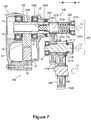
- FIG. 7 shows a drive unit 22B of the third embodiment.
- the drive unit 22B has a different construction from that of the drive unit 22 of the first embodiment.
- the power transmission mechanism 40B includes a motor shaft 33B of a motor 32B, an intermediate shaft 41 B, a rear wheel shaft (driving shaft) 42B, a first gear 43B, and a second gear 44B.
- Figure 7 shows a cross-section of the drive unit 22B that includes an axis L1 which represents the shaft center of the motor shaft 33B, an axis L2 which represents the shaft center of the intermediate shaft 41B, and an axis L3 which represents the shaft center of the rear wheel shaft 42B.
- the motor shaft 33B is made up of a first motor shaft portion 332B and a second motor shaft portion 333B.
- the first motor shaft portion 332B is positioned with a shaft center thereof coincident or consistent with the axis L1.
- the first motor shaft portion 332B has an annular cross-section perpendicular to the axis L1. That is, the first motor shaft portion 332B has a columnar hole extending therethrough in the direction of the shaft center.
- the greater part of the first motor shaft portion 332B is located within the space defined by the first and second motor case portions 38 and 39 of the motor 32.
- a plurality of spline grooves 335B are provided on the inner periphery of a right portion of the first motor shaft portion 332B.
- the second motor shaft portion 333B is positioned with a shaft center thereof coincident or consistent with the axis L1.
- the second motor shaft portion 333B is made up of a first portion 3331, a second portion 3332, a third portion 3333 and a fourth portion 3334.
- the first portion 3331 includes the left end surface of the second motor shaft portion 333B.
- the second portion 3332 is connected to the first portion 3331 and is located to the right of the first portion 3331.
- the third portion 3333 is connected to the second portion 3332 and is located to the right of the second portion 3332.
- the fourth portion 3334 is connected to the third portion 3333 and is located to the right of the third portion 3333.
- the fourth portion 3334 includes the right end surface of the second motor shaft portion 332B.
- the first portion 3331 is inserted into the hole of the first motor shaft portion 332B through its right end.
- Spline grooves 334B are provided on the outer periphery of the first portion 3331. The spline grooves 334B will be described further below.
- a plurality of gear grooves 331 B are provided on the second portion 3332.
- the gear grooves 331 B extend parallel to each other.
- the gear grooves 331 B extend parallel to the axis L1.
- An annular metal part 55B is fixed to the outer periphery of the third portion 3333 to cover the outer periphery.
- the metal part 55B is pushed into the third portion 3333.
- Portions of the metal part 55B located adjacent the right end of the third portion 3333 are bent along a plane perpendicular to the axis L1 to expand away from the axis L1.
- An elastic member 51 B is attached to the outer periphery of the third portion 3333.
- a bearing 339B is pushed into the fourth portion 3334.
- the outer ring of the bearing 339B is fixed to the housing 49 (not shown in Figure 7 ; see Figure 3 ).
- the intermediate shaft 41 B is positioned with its shaft center thereof coincident or consistent with the axis L2.
- the first gear 43B is fixed to the intermediate shaft 41 B.
- the first gear 43B is pushed into the intermediate shaft 41B.
- a plurality of gear grooves 432B are provided on the outer periphery of the first gear 43B.
- the gear grooves 432B extend parallel to each other.
- the gear grooves 432B extend in the direction of the axis L2.
- the gear grooves 432B engage the gear grooves 331 B provided on the second portion 3332 of the second motor shaft portion 333B.
- a plurality of gear grooves 411 B are provided on the outer periphery of the intermediate shaft 41 B.
- the gear grooves 411 B extend parallel to each other.
- the gear grooves 411 B extend in the direction of the axis L2.
- the gear grooves 411 B are located to the right of the portion of the shaft to which the first gear 43B is attached.
- the construction of the rear wheel shaft 42B is the same as that of the rear wheel shaft 42A in the second embodiment shown in Figure 6 .
- the rear wheel shaft 42B is positioned with a shaft center thereof coincident or consistent with the axis L3.
- the second gear 44B is fixed to the rear wheel shaft 42B.
- a plurality of gear grooves 442B are provided on the outer periphery of the second gear 44B.
- the gear grooves 442B engage the gear grooves 411 B on the intermediate shaft 41 B.
- the motor 32B drives the motor shaft 33B to cause the shaft to rotate in the forward direction.
- the rotation of the motor shaft 33B in the forward direction is transmitted to the first gear 43B in the form of rotation in the rearward direction.
- the intermediate shaft 41 B rotates in the rearward direction.
- the rotation of the intermediate shaft 41 B in the rearward direction is transmitted to the second gear 44B in the form of rotation in the forward direction.
- the second gear 44B rotates in the forward direction
- the rear wheel shaft 42B rotates in the forward direction, causing the electric motorcycle 10 to advance.
- a mechanism 50B for tolerating a rotation phase difference in the third embodiment is constructed on the motor shaft 33B.
- the mechanism 50B for tolerating a rotation phase difference will be described below.
- the mechanism 50B for tolerating a rotation phase difference is made up of the motor shaft 33B and an elastic member 51 B.
- Figure 7 shows the mechanism 50B for tolerating a rotation phase difference in a state found when the motor 32B is not rotating. The construction of the motor shaft 33B is described above.
- the elastic member 51 B is disposed on the third portion 3333 of the second motor shaft portion 333B.
- the elastic member 51 B is located between the right end of the gear groove 331 B portion and the left side of the bent portion of the metal part 55B.
- the elastic member 51 B is annular in shape.
- the elastic member 51 B can be extended and contracted in the direction of the axis L1.
- the elastic member 51 B may be a coil spring, for example.
- the spline grooves 334B provided on the first portion 3331 of the second motor shaft portion 333B are inclined at an angle relative to the axis L1.
- the inclination angle of the spline grooves 334B relative to the axis L1 may be in the range of 40 to 50 degrees, for example.
- the spline grooves 334B are disposed such that their left ends are located forward of their right ends.
- a plurality of spline grooves 335B are provided on the inner periphery of the right portion of the first motor shaft portion 332B.
- the spline grooves 335B are inclined at the same angle relative to the axis L1 as the spline grooves 334B on the second motor shaft portion 333B.
- the spline grooves 335B engage the spline grooves 334B on the second motor shaft portion 333B.
- Figure 7 shows the area where the spline grooves 334B and 335G are coupled to each other as a line parallel to the axis L1.
- the elastic member 51 B is at its natural length or has the minimum elastic force, as shown in Figure 7 .
- the rotation of the rotor 34 causes the first motor shaft portion 332B to rotate in the forward direction.
- the rotating force of the first motor shaft portion 332B in the forward direction is transmitted to the second motor shaft portion 333B via the engagement of the spline grooves 335B and the spline grooves 334B on the second motor shaft portion 333B. Since the spline grooves 334B and 335B are inclined relative to the axis L1, part of the rotating force acts as a force causing the second motor shaft portion 333B to rotate in the forward direction, while the remaining rotating force acts as a component of the force causing the second motor shaft portion 333B to move to the right in the direction of the axis L1. Thus, the elastic member 51 B is pushed by the right side of the second portion 3332 of the second motor shaft portion 333B so as to be contracted.
- the rotating force is used to rotating the second motor shaft portion 333B in the forward direction.
- the power transmission mechanism 40B in the present embodiment operates in the following manner when the electric motorcycle hits an obstacle, for example, and the rear wheel 11 R leaves the ground: when the rear wheel 11 R leaves the ground and then the rear wheel 11 R lands on the ground once again and the rear wheel shaft 42B stops temporarily, there is a time lag between the time at which the effect of the load applied to the rear wheel 11 R (that is, temporary halt of the rear wheel shaft 42B, intermediate shaft 41 B and second motor shaft portion 333B) occurs and the time at which this effect affects the driving of the motor 32 (that is, the first motor shaft portion 332B).
- the power transmission mechanism 40B in the present embodiment uses the mechanism 50B for tolerating a rotation phase difference described above to prevent overcurrent in the motor 32.
- the drive unit 22 is located to the left of the rear wheel 11 R; alternatively, the drive unit 22 may be located to the right of the rear wheel 11R.
- the power transmission mechanism includes a motor shaft, an intermediate shaft and a rear wheel shaft; however, the power transmission mechanism may not include an intermediate shaft.
- the rotating force of the motor shaft can be transmitted to the rear wheel shaft via gears.
- the mechanism for tolerating a rotation phase difference may be provided on the rear wheel shaft, or provided on the motor shaft.
- straddled vehicle or motor vehicle used herein, and as used in the art, is meant to include at least the following terms also used in the art:
Landscapes
- Engineering & Computer Science (AREA)
- Chemical & Material Sciences (AREA)
- Combustion & Propulsion (AREA)
- Mechanical Engineering (AREA)
- Transportation (AREA)
- Electric Propulsion And Braking For Vehicles (AREA)
- Motor Power Transmission Devices (AREA)
Applications Claiming Priority (1)
| Application Number | Priority Date | Filing Date | Title |
|---|---|---|---|
| JP2015112567A JP2016222183A (ja) | 2015-06-02 | 2015-06-02 | 鞍乗型電動車両 |
Publications (3)
| Publication Number | Publication Date |
|---|---|
| EP3100941A2 true EP3100941A2 (fr) | 2016-12-07 |
| EP3100941A3 EP3100941A3 (fr) | 2017-06-07 |
| EP3100941B1 EP3100941B1 (fr) | 2021-02-24 |
Family
ID=56096463
Family Applications (1)
| Application Number | Title | Priority Date | Filing Date |
|---|---|---|---|
| EP16170745.0A Active EP3100941B1 (fr) | 2015-06-02 | 2016-05-20 | Véhicule électrique à califourchon |
Country Status (4)
| Country | Link |
|---|---|
| US (1) | US20160355087A1 (fr) |
| EP (1) | EP3100941B1 (fr) |
| JP (1) | JP2016222183A (fr) |
| TW (1) | TWI609816B (fr) |
Families Citing this family (2)
| Publication number | Priority date | Publication date | Assignee | Title |
|---|---|---|---|---|
| CN113765300B (zh) * | 2018-09-28 | 2025-02-11 | 日本电产株式会社 | 马达单元 |
| JP7185472B2 (ja) * | 2018-10-02 | 2022-12-07 | 株式会社マキタ | 電動工具 |
Citations (1)
| Publication number | Priority date | Publication date | Assignee | Title |
|---|---|---|---|---|
| WO2012090245A1 (fr) | 2010-12-27 | 2012-07-05 | 川崎重工業株式会社 | Véhicule électrique de type à selle |
Family Cites Families (15)
| Publication number | Priority date | Publication date | Assignee | Title |
|---|---|---|---|---|
| JPS56127447U (fr) * | 1980-02-29 | 1981-09-28 | ||
| JPS61157851A (ja) * | 1984-12-27 | 1986-07-17 | Suzuki Motor Co Ltd | ダンパ構造 |
| JPS6298030A (ja) * | 1985-10-24 | 1987-05-07 | Daikin Mfg Co Ltd | ダンパ− |
| JPS6330635U (fr) * | 1986-08-14 | 1988-02-29 | ||
| JPH06199267A (ja) * | 1992-12-28 | 1994-07-19 | Suzuki Motor Corp | 前後輪駆動二輪車の前輪への動力伝導装置 |
| JPH08207873A (ja) * | 1994-11-30 | 1996-08-13 | Suzuki Motor Corp | 補助動力アシスト式自転車 |
| JP3415325B2 (ja) * | 1995-04-27 | 2003-06-09 | ブリヂストンサイクル株式会社 | 自転車用トルク検出装置 |
| JPH0920280A (ja) * | 1995-07-06 | 1997-01-21 | Matsushita Electric Ind Co Ltd | 電動自転車 |
| JP3795200B2 (ja) * | 1997-09-14 | 2006-07-12 | 本田技研工業株式会社 | 自動二輪車のパワーユニット |
| JP2004236386A (ja) * | 2003-01-28 | 2004-08-19 | Suzuki Motor Corp | 電動車両の駆動装置 |
| JP4103629B2 (ja) * | 2003-02-27 | 2008-06-18 | 株式会社ジェイテクト | 動力伝達装置 |
| JP5727729B2 (ja) * | 2010-07-20 | 2015-06-03 | 川崎重工業株式会社 | 車両の制御装置 |
| JP5602697B2 (ja) * | 2011-09-05 | 2014-10-08 | 本田技研工業株式会社 | カム式トルクダンパ |
| JP6232915B2 (ja) * | 2013-10-16 | 2017-11-22 | スズキ株式会社 | ハイブリッド二輪車 |
| TWM481159U (zh) * | 2014-03-24 | 2014-07-01 | Lorom Ind Co Ltd | 電動車輛傳動系統 |
-
2015
- 2015-06-02 JP JP2015112567A patent/JP2016222183A/ja not_active Ceased
-
2016
- 2016-05-10 TW TW105114466A patent/TWI609816B/zh active
- 2016-05-20 EP EP16170745.0A patent/EP3100941B1/fr active Active
- 2016-05-26 US US15/164,948 patent/US20160355087A1/en not_active Abandoned
Patent Citations (1)
| Publication number | Priority date | Publication date | Assignee | Title |
|---|---|---|---|---|
| WO2012090245A1 (fr) | 2010-12-27 | 2012-07-05 | 川崎重工業株式会社 | Véhicule électrique de type à selle |
Also Published As
| Publication number | Publication date |
|---|---|
| TWI609816B (zh) | 2018-01-01 |
| TW201702119A (zh) | 2017-01-16 |
| US20160355087A1 (en) | 2016-12-08 |
| EP3100941A3 (fr) | 2017-06-07 |
| JP2016222183A (ja) | 2016-12-28 |
| EP3100941B1 (fr) | 2021-02-24 |
Similar Documents
| Publication | Publication Date | Title |
|---|---|---|
| US10703433B2 (en) | Drive device for a bicycle driven by an electric motor | |
| US9915302B2 (en) | Drive unit and electric-motor-assisted bicycle | |
| TWI697432B (zh) | 用於輪式車的懸架組件 | |
| TWI698369B (zh) | 用於自行車的懸架組件 | |
| US10850798B2 (en) | Bicycle rear suspension | |
| US8375827B2 (en) | Bicycle crank assembly | |
| CA2461766C (fr) | Suspension arriere en porte a faux pour bicyclette | |
| JP2005271911A (ja) | 自転車用変速装置 | |
| US9855794B1 (en) | Bicycle hub assembly | |
| JP2009107615A (ja) | 自転車の伝動システム | |
| EP3100941B1 (fr) | Véhicule électrique à califourchon | |
| US11932345B2 (en) | Leaning-type vehicle | |
| EP3150477A1 (fr) | Véhicule monté à califourchon | |
| US6918467B2 (en) | Counter-rotating brake disc for a motorcycle wheel assembly | |
| EP2075481B1 (fr) | Embrayage centrifuge | |
| US20030227156A1 (en) | Body frame structure for bicycle | |
| EP4059823A2 (fr) | Ensemble entraînement séquentiel adjacent pour une bicyclette | |
| EP4269221A1 (fr) | Ensemble guidon et véhicule de type à enfourcher | |
| CN101348157A (zh) | 一种摩托车平叉 | |
| CN100358773C (zh) | 自行车 | |
| FR3095801A1 (fr) | Pédalier à plateau mobile | |
| WO2021064983A1 (fr) | Mécanisme de direction de roue avant dans une direction à moyeu central | |
| US20220297793A1 (en) | Sequential adjacent drive assembly for a cycle | |
| EP4155174A1 (fr) | Roue anti-effet gyroscopique | |
| JP6598176B1 (ja) | クランク軸へのギヤ板の取付構造 |
Legal Events
| Date | Code | Title | Description |
|---|---|---|---|
| PUAI | Public reference made under article 153(3) epc to a published international application that has entered the european phase |
Free format text: ORIGINAL CODE: 0009012 |
|
| STAA | Information on the status of an ep patent application or granted ep patent |
Free format text: STATUS: THE APPLICATION HAS BEEN PUBLISHED |
|
| AK | Designated contracting states |
Kind code of ref document: A2 Designated state(s): AL AT BE BG CH CY CZ DE DK EE ES FI FR GB GR HR HU IE IS IT LI LT LU LV MC MK MT NL NO PL PT RO RS SE SI SK SM TR |
|
| AX | Request for extension of the european patent |
Extension state: BA ME |
|
| AK | Designated contracting states |
Kind code of ref document: A3 Designated state(s): AL AT BE BG CH CY CZ DE DK EE ES FI FR GB GR HR HU IE IS IT LI LT LU LV MC MK MT NL NO PL PT RO RS SE SI SK SM TR |
|
| AX | Request for extension of the european patent |
Extension state: BA ME |
|
| RIC1 | Information provided on ipc code assigned before grant |
Ipc: B62M 11/06 20060101AFI20170503BHEP Ipc: F16H 1/00 20060101ALI20170503BHEP Ipc: F16F 15/121 20060101ALI20170503BHEP Ipc: B62M 7/12 20060101ALI20170503BHEP Ipc: B62M 21/00 20060101ALI20170503BHEP Ipc: F16D 3/12 20060101ALI20170503BHEP Ipc: B62M 11/02 20060101ALI20170503BHEP |
|
| PUAL | Search report despatched |
Free format text: ORIGINAL CODE: 0009013 |
|
| STAA | Information on the status of an ep patent application or granted ep patent |
Free format text: STATUS: REQUEST FOR EXAMINATION WAS MADE |
|
| 17P | Request for examination filed |
Effective date: 20171020 |
|
| RBV | Designated contracting states (corrected) |
Designated state(s): AL AT BE BG CH CY CZ DE DK EE ES FI FR GB GR HR HU IE IS IT LI LT LU LV MC MK MT NL NO PL PT RO RS SE SI SK SM TR |
|
| GRAP | Despatch of communication of intention to grant a patent |
Free format text: ORIGINAL CODE: EPIDOSNIGR1 |
|
| STAA | Information on the status of an ep patent application or granted ep patent |
Free format text: STATUS: GRANT OF PATENT IS INTENDED |
|
| RIC1 | Information provided on ipc code assigned before grant |
Ipc: B62M 11/06 20060101AFI20200812BHEP Ipc: F16F 15/121 20060101ALI20200812BHEP Ipc: B62M 21/00 20060101ALI20200812BHEP Ipc: F16D 3/12 20060101ALI20200812BHEP Ipc: F16H 1/00 20060101ALI20200812BHEP Ipc: B62M 11/02 20060101ALI20200812BHEP Ipc: B62M 7/12 20060101ALI20200812BHEP |
|
| INTG | Intention to grant announced |
Effective date: 20200910 |
|
| GRAS | Grant fee paid |
Free format text: ORIGINAL CODE: EPIDOSNIGR3 |
|
| GRAA | (expected) grant |
Free format text: ORIGINAL CODE: 0009210 |
|
| STAA | Information on the status of an ep patent application or granted ep patent |
Free format text: STATUS: THE PATENT HAS BEEN GRANTED |
|
| AK | Designated contracting states |
Kind code of ref document: B1 Designated state(s): AL AT BE BG CH CY CZ DE DK EE ES FI FR GB GR HR HU IE IS IT LI LT LU LV MC MK MT NL NO PL PT RO RS SE SI SK SM TR |
|
| REG | Reference to a national code |
Ref country code: CH Ref legal event code: EP |
|
| REG | Reference to a national code |
Ref country code: AT Ref legal event code: REF Ref document number: 1364133 Country of ref document: AT Kind code of ref document: T Effective date: 20210315 |
|
| REG | Reference to a national code |
Ref country code: IE Ref legal event code: FG4D |
|
| REG | Reference to a national code |
Ref country code: DE Ref legal event code: R096 Ref document number: 602016052974 Country of ref document: DE |
|
| REG | Reference to a national code |
Ref country code: LT Ref legal event code: MG9D |
|
| REG | Reference to a national code |
Ref country code: NL Ref legal event code: MP Effective date: 20210224 |
|
| PG25 | Lapsed in a contracting state [announced via postgrant information from national office to epo] |
Ref country code: GR Free format text: LAPSE BECAUSE OF FAILURE TO SUBMIT A TRANSLATION OF THE DESCRIPTION OR TO PAY THE FEE WITHIN THE PRESCRIBED TIME-LIMIT Effective date: 20210525 Ref country code: FI Free format text: LAPSE BECAUSE OF FAILURE TO SUBMIT A TRANSLATION OF THE DESCRIPTION OR TO PAY THE FEE WITHIN THE PRESCRIBED TIME-LIMIT Effective date: 20210224 Ref country code: HR Free format text: LAPSE BECAUSE OF FAILURE TO SUBMIT A TRANSLATION OF THE DESCRIPTION OR TO PAY THE FEE WITHIN THE PRESCRIBED TIME-LIMIT Effective date: 20210224 Ref country code: LT Free format text: LAPSE BECAUSE OF FAILURE TO SUBMIT A TRANSLATION OF THE DESCRIPTION OR TO PAY THE FEE WITHIN THE PRESCRIBED TIME-LIMIT Effective date: 20210224 Ref country code: BG Free format text: LAPSE BECAUSE OF FAILURE TO SUBMIT A TRANSLATION OF THE DESCRIPTION OR TO PAY THE FEE WITHIN THE PRESCRIBED TIME-LIMIT Effective date: 20210524 Ref country code: NO Free format text: LAPSE BECAUSE OF FAILURE TO SUBMIT A TRANSLATION OF THE DESCRIPTION OR TO PAY THE FEE WITHIN THE PRESCRIBED TIME-LIMIT Effective date: 20210524 Ref country code: PT Free format text: LAPSE BECAUSE OF FAILURE TO SUBMIT A TRANSLATION OF THE DESCRIPTION OR TO PAY THE FEE WITHIN THE PRESCRIBED TIME-LIMIT Effective date: 20210624 |
|
| REG | Reference to a national code |
Ref country code: AT Ref legal event code: MK05 Ref document number: 1364133 Country of ref document: AT Kind code of ref document: T Effective date: 20210224 |
|
| PG25 | Lapsed in a contracting state [announced via postgrant information from national office to epo] |
Ref country code: SE Free format text: LAPSE BECAUSE OF FAILURE TO SUBMIT A TRANSLATION OF THE DESCRIPTION OR TO PAY THE FEE WITHIN THE PRESCRIBED TIME-LIMIT Effective date: 20210224 Ref country code: NL Free format text: LAPSE BECAUSE OF FAILURE TO SUBMIT A TRANSLATION OF THE DESCRIPTION OR TO PAY THE FEE WITHIN THE PRESCRIBED TIME-LIMIT Effective date: 20210224 Ref country code: PL Free format text: LAPSE BECAUSE OF FAILURE TO SUBMIT A TRANSLATION OF THE DESCRIPTION OR TO PAY THE FEE WITHIN THE PRESCRIBED TIME-LIMIT Effective date: 20210224 Ref country code: LV Free format text: LAPSE BECAUSE OF FAILURE TO SUBMIT A TRANSLATION OF THE DESCRIPTION OR TO PAY THE FEE WITHIN THE PRESCRIBED TIME-LIMIT Effective date: 20210224 Ref country code: RS Free format text: LAPSE BECAUSE OF FAILURE TO SUBMIT A TRANSLATION OF THE DESCRIPTION OR TO PAY THE FEE WITHIN THE PRESCRIBED TIME-LIMIT Effective date: 20210224 |
|
| PG25 | Lapsed in a contracting state [announced via postgrant information from national office to epo] |
Ref country code: IS Free format text: LAPSE BECAUSE OF FAILURE TO SUBMIT A TRANSLATION OF THE DESCRIPTION OR TO PAY THE FEE WITHIN THE PRESCRIBED TIME-LIMIT Effective date: 20210624 |
|
| PG25 | Lapsed in a contracting state [announced via postgrant information from national office to epo] |
Ref country code: AT Free format text: LAPSE BECAUSE OF FAILURE TO SUBMIT A TRANSLATION OF THE DESCRIPTION OR TO PAY THE FEE WITHIN THE PRESCRIBED TIME-LIMIT Effective date: 20210224 Ref country code: SM Free format text: LAPSE BECAUSE OF FAILURE TO SUBMIT A TRANSLATION OF THE DESCRIPTION OR TO PAY THE FEE WITHIN THE PRESCRIBED TIME-LIMIT Effective date: 20210224 Ref country code: EE Free format text: LAPSE BECAUSE OF FAILURE TO SUBMIT A TRANSLATION OF THE DESCRIPTION OR TO PAY THE FEE WITHIN THE PRESCRIBED TIME-LIMIT Effective date: 20210224 Ref country code: CZ Free format text: LAPSE BECAUSE OF FAILURE TO SUBMIT A TRANSLATION OF THE DESCRIPTION OR TO PAY THE FEE WITHIN THE PRESCRIBED TIME-LIMIT Effective date: 20210224 |
|
| REG | Reference to a national code |
Ref country code: DE Ref legal event code: R097 Ref document number: 602016052974 Country of ref document: DE |
|
| PG25 | Lapsed in a contracting state [announced via postgrant information from national office to epo] |
Ref country code: ES Free format text: LAPSE BECAUSE OF FAILURE TO SUBMIT A TRANSLATION OF THE DESCRIPTION OR TO PAY THE FEE WITHIN THE PRESCRIBED TIME-LIMIT Effective date: 20210224 Ref country code: DK Free format text: LAPSE BECAUSE OF FAILURE TO SUBMIT A TRANSLATION OF THE DESCRIPTION OR TO PAY THE FEE WITHIN THE PRESCRIBED TIME-LIMIT Effective date: 20210224 Ref country code: SK Free format text: LAPSE BECAUSE OF FAILURE TO SUBMIT A TRANSLATION OF THE DESCRIPTION OR TO PAY THE FEE WITHIN THE PRESCRIBED TIME-LIMIT Effective date: 20210224 Ref country code: RO Free format text: LAPSE BECAUSE OF FAILURE TO SUBMIT A TRANSLATION OF THE DESCRIPTION OR TO PAY THE FEE WITHIN THE PRESCRIBED TIME-LIMIT Effective date: 20210224 |
|
| REG | Reference to a national code |
Ref country code: CH Ref legal event code: PL |
|
| PLBE | No opposition filed within time limit |
Free format text: ORIGINAL CODE: 0009261 |
|
| STAA | Information on the status of an ep patent application or granted ep patent |
Free format text: STATUS: NO OPPOSITION FILED WITHIN TIME LIMIT |
|
| GBPC | Gb: european patent ceased through non-payment of renewal fee |
Effective date: 20210524 |
|
| PG25 | Lapsed in a contracting state [announced via postgrant information from national office to epo] |
Ref country code: LI Free format text: LAPSE BECAUSE OF NON-PAYMENT OF DUE FEES Effective date: 20210531 Ref country code: MC Free format text: LAPSE BECAUSE OF FAILURE TO SUBMIT A TRANSLATION OF THE DESCRIPTION OR TO PAY THE FEE WITHIN THE PRESCRIBED TIME-LIMIT Effective date: 20210224 Ref country code: LU Free format text: LAPSE BECAUSE OF NON-PAYMENT OF DUE FEES Effective date: 20210520 Ref country code: CH Free format text: LAPSE BECAUSE OF NON-PAYMENT OF DUE FEES Effective date: 20210531 Ref country code: AL Free format text: LAPSE BECAUSE OF FAILURE TO SUBMIT A TRANSLATION OF THE DESCRIPTION OR TO PAY THE FEE WITHIN THE PRESCRIBED TIME-LIMIT Effective date: 20210224 |
|
| 26N | No opposition filed |
Effective date: 20211125 |
|
| REG | Reference to a national code |
Ref country code: BE Ref legal event code: MM Effective date: 20210531 |
|
| PG25 | Lapsed in a contracting state [announced via postgrant information from national office to epo] |
Ref country code: SI Free format text: LAPSE BECAUSE OF FAILURE TO SUBMIT A TRANSLATION OF THE DESCRIPTION OR TO PAY THE FEE WITHIN THE PRESCRIBED TIME-LIMIT Effective date: 20210224 |
|
| PG25 | Lapsed in a contracting state [announced via postgrant information from national office to epo] |
Ref country code: IT Free format text: LAPSE BECAUSE OF FAILURE TO SUBMIT A TRANSLATION OF THE DESCRIPTION OR TO PAY THE FEE WITHIN THE PRESCRIBED TIME-LIMIT Effective date: 20210224 Ref country code: IE Free format text: LAPSE BECAUSE OF NON-PAYMENT OF DUE FEES Effective date: 20210520 Ref country code: GB Free format text: LAPSE BECAUSE OF NON-PAYMENT OF DUE FEES Effective date: 20210524 |
|
| PG25 | Lapsed in a contracting state [announced via postgrant information from national office to epo] |
Ref country code: IS Free format text: LAPSE BECAUSE OF FAILURE TO SUBMIT A TRANSLATION OF THE DESCRIPTION OR TO PAY THE FEE WITHIN THE PRESCRIBED TIME-LIMIT Effective date: 20210624 Ref country code: FR Free format text: LAPSE BECAUSE OF NON-PAYMENT OF DUE FEES Effective date: 20210531 |
|
| PG25 | Lapsed in a contracting state [announced via postgrant information from national office to epo] |
Ref country code: BE Free format text: LAPSE BECAUSE OF NON-PAYMENT OF DUE FEES Effective date: 20210531 |
|
| PG25 | Lapsed in a contracting state [announced via postgrant information from national office to epo] |
Ref country code: HU Free format text: LAPSE BECAUSE OF FAILURE TO SUBMIT A TRANSLATION OF THE DESCRIPTION OR TO PAY THE FEE WITHIN THE PRESCRIBED TIME-LIMIT; INVALID AB INITIO Effective date: 20160520 |
|
| PG25 | Lapsed in a contracting state [announced via postgrant information from national office to epo] |
Ref country code: CY Free format text: LAPSE BECAUSE OF FAILURE TO SUBMIT A TRANSLATION OF THE DESCRIPTION OR TO PAY THE FEE WITHIN THE PRESCRIBED TIME-LIMIT Effective date: 20210224 |
|
| PG25 | Lapsed in a contracting state [announced via postgrant information from national office to epo] |
Ref country code: MK Free format text: LAPSE BECAUSE OF FAILURE TO SUBMIT A TRANSLATION OF THE DESCRIPTION OR TO PAY THE FEE WITHIN THE PRESCRIBED TIME-LIMIT Effective date: 20210224 |
|
| PG25 | Lapsed in a contracting state [announced via postgrant information from national office to epo] |
Ref country code: MT Free format text: LAPSE BECAUSE OF FAILURE TO SUBMIT A TRANSLATION OF THE DESCRIPTION OR TO PAY THE FEE WITHIN THE PRESCRIBED TIME-LIMIT Effective date: 20210224 |
|
| PGFP | Annual fee paid to national office [announced via postgrant information from national office to epo] |
Ref country code: DE Payment date: 20250521 Year of fee payment: 10 |
|
| PG25 | Lapsed in a contracting state [announced via postgrant information from national office to epo] |
Ref country code: TR Free format text: LAPSE BECAUSE OF FAILURE TO SUBMIT A TRANSLATION OF THE DESCRIPTION OR TO PAY THE FEE WITHIN THE PRESCRIBED TIME-LIMIT Effective date: 20210224 |