EP3103420B1 - Mandibuläre vorschubvorrichtung - Google Patents
Mandibuläre vorschubvorrichtung Download PDFInfo
- Publication number
- EP3103420B1 EP3103420B1 EP15707404.8A EP15707404A EP3103420B1 EP 3103420 B1 EP3103420 B1 EP 3103420B1 EP 15707404 A EP15707404 A EP 15707404A EP 3103420 B1 EP3103420 B1 EP 3103420B1
- Authority
- EP
- European Patent Office
- Prior art keywords
- strap
- slot
- mouthpiece
- protrusion
- lower portion
- Prior art date
- Legal status (The legal status is an assumption and is not a legal conclusion. Google has not performed a legal analysis and makes no representation as to the accuracy of the status listed.)
- Active
Links
Images






Classifications
-
- A—HUMAN NECESSITIES
- A61—MEDICAL OR VETERINARY SCIENCE; HYGIENE
- A61C—DENTISTRY; APPARATUS OR METHODS FOR ORAL OR DENTAL HYGIENE
- A61C7/00—Orthodontics, i.e. obtaining or maintaining the desired position of teeth, e.g. by straightening, evening, regulating, separating, or by correcting malocclusions
- A61C7/08—Mouthpiece-type retainers or positioners, e.g. for both the lower and upper arch
-
- A—HUMAN NECESSITIES
- A61—MEDICAL OR VETERINARY SCIENCE; HYGIENE
- A61C—DENTISTRY; APPARATUS OR METHODS FOR ORAL OR DENTAL HYGIENE
- A61C7/00—Orthodontics, i.e. obtaining or maintaining the desired position of teeth, e.g. by straightening, evening, regulating, separating, or by correcting malocclusions
- A61C7/36—Devices acting between upper and lower teeth
-
- A—HUMAN NECESSITIES
- A61—MEDICAL OR VETERINARY SCIENCE; HYGIENE
- A61F—FILTERS IMPLANTABLE INTO BLOOD VESSELS; PROSTHESES; DEVICES PROVIDING PATENCY TO, OR PREVENTING COLLAPSING OF, TUBULAR STRUCTURES OF THE BODY, e.g. STENTS; ORTHOPAEDIC, NURSING OR CONTRACEPTIVE DEVICES; FOMENTATION; TREATMENT OR PROTECTION OF EYES OR EARS; BANDAGES, DRESSINGS OR ABSORBENT PADS; FIRST-AID KITS
- A61F5/00—Orthopaedic methods or devices for non-surgical treatment of bones or joints; Nursing devices ; Anti-rape devices
- A61F5/56—Devices for preventing snoring
- A61F5/566—Intra-oral devices
-
- A—HUMAN NECESSITIES
- A61—MEDICAL OR VETERINARY SCIENCE; HYGIENE
- A61F—FILTERS IMPLANTABLE INTO BLOOD VESSELS; PROSTHESES; DEVICES PROVIDING PATENCY TO, OR PREVENTING COLLAPSING OF, TUBULAR STRUCTURES OF THE BODY, e.g. STENTS; ORTHOPAEDIC, NURSING OR CONTRACEPTIVE DEVICES; FOMENTATION; TREATMENT OR PROTECTION OF EYES OR EARS; BANDAGES, DRESSINGS OR ABSORBENT PADS; FIRST-AID KITS
- A61F5/00—Orthopaedic methods or devices for non-surgical treatment of bones or joints; Nursing devices ; Anti-rape devices
- A61F5/56—Devices for preventing snoring
- A61F2005/563—Anti-bruxisme
-
- Y—GENERAL TAGGING OF NEW TECHNOLOGICAL DEVELOPMENTS; GENERAL TAGGING OF CROSS-SECTIONAL TECHNOLOGIES SPANNING OVER SEVERAL SECTIONS OF THE IPC; TECHNICAL SUBJECTS COVERED BY FORMER USPC CROSS-REFERENCE ART COLLECTIONS [XRACs] AND DIGESTS
- Y10—TECHNICAL SUBJECTS COVERED BY FORMER USPC
- Y10T—TECHNICAL SUBJECTS COVERED BY FORMER US CLASSIFICATION
- Y10T29/00—Metal working
- Y10T29/49—Method of mechanical manufacture
- Y10T29/49826—Assembling or joining
Definitions
- the invention relates to a mandibular advancement device intended to be placed in a person's mouth and cause a slight advancement of the lower jaw so as to avoid the obstruction of airways.
- the main application of this type of device is the treatment of sleep apnea.
- the disclosure also relates to a preparation method and kit for this device.
- Snoring While people are asleep, the muscles relax causing the airways to close and vibrate as air is passed. This vibration causes the noise known as snoring. Snoring, however, is not the only problem caused by the obstruction of the airways. This obstruction also causes insufficient ventilation of the lungs, leading to disturbed sleep and, potentially, to the person's breathing to stop for a moment (this being known as sleep apnea).
- the apnea phenomenon takes place as follows: after snoring regularly for a period of time, the snoring is suddenly interrupted by a brief period of silence in which breathing momentarily stops; this period without breathing (apnea) ends with a snort or gasp, after which normal breathing is gradually resumed, and the snoring begins again. This pattern may be repeated frequently during the night. Sleep apnea may lead to health problems and even death, and is therefore a serious health problem. This problem often arises in those suffering from obesity or in middle-aged men, although other factors such as alcohol or tobacco consumption and the anatomy of the nasal passage are also influential.
- apnea Diverse treatments for apnea are known which seek to normalize the patient's breathing during sleep. On one hand, apnea can be treated by reducing the risk factors in the patient's life. On the other hand, diverse devices are available on the market, which are intended to act on the patient in order to reduce sleep apnea. One type of device is based on injecting compressed air through a mask worn by the patient whilst sleeping, to ensure the controlled and regular opening of the airways.
- a mandibular advancement device is placed inside the patient's mouth and causes a slight forward movement of the mandible with respect to the upper maxillary bone, opening a bigger space at the back of the oral cavity, hence facilitating the passage of air from and to the pharynx.
- apnea can also be treated by surgery if the aforementioned treatments are not effective.
- Mandibular advancement devices are usually made up of a mouthpiece, which is custom-made for the patient, with an upper portion which is to be placed in the upper dental arch and a lower portion to be placed in the lower dental arch.
- Mandibular advancement mechanisms are connected between the upper portion and the lower portion, and are positioned and tightened so that the lower portion is kept further forward than the upper portion, compared with a rest position in which both portions are located above each other in accordance with the patient's normal bite.
- mandibular advancement mechanisms there are metal mechanisms consisting of a lower part and an upper part connected to the lower portion and the upper portion of the mouthpiece respectively.
- the lower part and the upper part are interconnected in a longitudinally adjustable manner, for example via an adjustable threaded connection, which enables the position of the lower portion of the mouthpiece to be adjusted with respect to the upper portion.
- These mandibular advancement devices based on metal mechanisms usually present the drawback of being extremely rigid and uncomfortable for the patient.
- plastic mandibular advancement mechanisms are also available, which generally consist of one or more plastic straps that are connected between the lower portion and the upper portion of the mouthpiece.
- the mechanism is made up of a single strap laid in the form of a connection rod in the front area of the upper and lower portions, connecting them so that the mandible is brought forward with respect to the upper maxillary bone.
- the mechanism consists of two straps, one on each side of the mouthpiece, the ends of which are connected from a side of the lower portion to the same side of the upper portion.
- a single strap is provided whose ends are connected to the opposing sides of the lower portion and whose central area is supported on the front of the upper portion of the mouthpiece.
- the devices fitted with plastic mandibular advancement mechanisms are more comfortable for the patient as they provide certain lateral and/or longitudinal flexibility allowing the patient to move his or her jaw slightly during sleep, whilst maintaining it properly forward with respect to the upper jaw, achieving greater comfort and adaptation for the patient.
- Other known mandibular advancement devices are disclosed, for example, in WO2013/049751 A2 , US6325064 B1 , EP1658823 A1 , CN201422945 , or DE202008016373 U1 , on which the preamble of appended claim 1 is based.
- the invention aims to provide an improved mandibular advancement device, offering the patient even greater comfort whilst ensuring the same or better mandibular advancement for the treatment of sleep apnea.
- the object of the invention is a mandibular advancement device as defined in independent claim 1.
- the device comprises a mouthpiece made up of an upper portion and a lower portion, where both portions include a front area intended to be placed in the area of the incisor and canine teeth, and two lateral areas intended to be placed in the area of the premolar and molar teeth.
- the device in accordance with the invention presents the peculiarity that it comprises at least one plastic strap (cord), at each end of which a slot is provided. The slot is connected articulately to a respective protrusion which protrudes transversely from the mouthpiece.
- the slot is closed and its length is longer than that of the diameter of a cylindrical portion of the protrusion, so that the cylindrical portion can move along the slot.
- the mandibular advancement device is prepared or assembled starting with a patient's mouthpiece. Preparation is commenced by placing the mouthpiece in a position previously established by the doctor, in which the lower portion of the mouthpiece is placed sufficiently forward with respect to the upper portion so that, if the mouthpiece were placed inside the patient in this position, the mouthpiece would cause sufficient mandibular advancement so as to prevent apnea. This position that has been previously established by the doctor will be referred to as the "treatment position" throughout this document.
- the strap or straps are articulately fixed to the mouthpiece by coupling the outer ends of the strap slots with the respective lateral protrusions of the mouthpiece.
- the protrusions are at the outer ends of the strap slots.
- the device in accordance with the invention when the device in accordance with the invention is placed onto the patient, it initially forces the patient to adopt the treatment position, i.e., the position defined by the doctor as ideal for treating the apnea. From this position, the device in accordance with the invention does not allow the mandible to move backwards due to the traction exercised by the straps. On the other hand, the patient is able to slightly move the mandible forward, as far as the protrusions can move along the grooves, allowing certain freedom of movement and comfort for the patient. The patient will also be able to open and close his or her mouth, due to the fact that the straps are articulately connected to the mouthpiece (and therefore the straps work like articulated links).
- the position of the protrusions within the slots also allows the patient to slightly move his or her jaw in a transversal direction. Therefore, by preventing the backward movement of the jaw, the device in accordance with the invention allows the patient's apnea to be effectively treated; at the same time, the freedom of movement in the rest of the directions increases comfort, reduces any dental pain that may occur as a result of prolonged use of the device, and, in short, increases the patient's acceptance of the apnea treatment.
- the device may include with two straps, one on each side of the mouthpiece, or one strap that extends from one side of the mouthpiece to the other.
- the articulated connections between the portions of the mouthpiece and the straps are carried out as explained, i.e., at the outer ends of the strap slots when the device is in the treatment position that has been pre-established by the doctor.
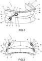
- FIGS 1 and 2 show a perspective view and a front view of first embodiment of a mandibular advancement device in accordance with the invention.
- the device (1) of the present embodiment comprises a mouthpiece (2), generally custom-made for the patient, comprising an upper portion (3) intended to be placed on the upper dental arch and a lower portion (4) intended to be placed on the lower dental arch.
- the mouthpiece (2) may be a bite splint, which is a specific type of mouthpiece designed to treat bruxism, a clinical phenomenon consisting of undesired and excessive grinding and/or clenching of teeth.
- the mouthpiece may be manufactured with vacuum sheets, using CAD/CAM, by dust apposition, or by any other applicable manufacturing system.
- Each portion (3, 4) of the mouthpiece (2) includes a front area (3a, 4a) intended to be placed alongside the user's incisor and canine teeth, and two lateral areas (3b, 4b) intended to be placed in the area of the user's premolar and molar teeth.
- the device (1) in accordance with the invention and of the present embodiment further includes two plastic straps (5), one on each side of the mouthpiece (2).
- Each strap (5) comprises an elongate body (6) fitted with a respective connector (8) at each end (7) thereof.
- Each connector (8) includes a respective slot (9).
- the body (6) of the present embodiment is a single cord, which is an extremely resistant solution in mechanical terms, is unlikely to break, at can be manufactured easily and at reasonable cost.
- the slots (9) at the ends (7) of the straps (5) are articulately connected to protrusions (10) on the mouthpiece (2). More specifically, in this embodiment, the slot (9) at the upper end (7) of each strap (5), according to the position in Figure 1 , is articulately connected to a protrusion (10) that protrudes from the lateral area (3b) of the upper portion (3), whilst the slot (9) at the lower end (7) is articulately connected to a protrusion (10) that protrudes from the lateral area (4b) of the lower portion (4).
- the plastic material used to make the strap (5) should be relatively rigid but should also have certain elasticity to deformation.
- suitable materials for the straps are Polyamide 12 or Nylon 6.3, although these examples are not intended to be limiting and use of other materials is not ruled out.
- Figure 3 shows a partial left side elevation view of the device (1) of Figure 1 , in which only the area of the lower end (7) of the left-hand strap (5) according to the position of the device (1) in Figure 1 is shown.
- Figure 4 shows a cross-sectional view of the assembly of Figure 3 as per sectional plan IV-IV.
- the protrusion (10) comprises a cylindrical portion (11) and a head (12).
- the head (12) is placed further out and is wider than the cylindrical portion (11), the purpose of this head (12) being to prevent the end (7) of the strap (5) from disconnecting from the protrusion (10).
- the cylindrical portion (11) is arranged inside the slot (9) of the strap (5).
- Connecting the slot (9) to a cylindrical-shaped part allows achieving an articulating connection between the strap (5) and the lower portion (4) of the mouthpiece (2), so that the strap (5) acts like an articulated link.
- the articulated connection is favored by the fact that the connector (8) comprises a closed loop having two straight lateral portions (13) and two curved end portions (14), for example in the shape of an arc of a circle.
- the slot (9) is closed and its length is longer than the diameter of the cylindrical portion (11). This enables the cylindrical portion (11) to move longitudinally along the slot (9), as well as to rotate with respect to the slot (9).
- the usefulness of this longitudinal displacement is illustrated in the following four figures.
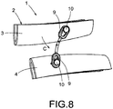
- Figures 5 to 8 show various side views of the device (1) of Figure 1 in different positions.
- Figure 5 shows the device (1) in an initial or rest position, in which the lower portion (4) of the mouthpiece (2) is slightly advanced with respect to the upper portion (3).
- This position will hereinafter be called the "treatment position", as it is a position that has been designed and planned by a medical professional to provide appropriate mandibular advancement and to open the airways of a certain patient during sleep.
- the protrusions (10) and the strap (5) are positioned in such a way that the strap acts by traction; i.e., if the lower portion (4) tries to move backwards - in the direction indicated by arrow (A)- the strap (5) pulls on the lower portion (4) and prevents such movement.
- the device (1) does allow the patient to move the lower portion (4) of the mouthpiece (2) forward, i.e., in the direction indicated by arrow (B), as can be seen in Figures 6 and 7 .
- the device allows forward movement because the two slots (9) can move in the direction of arrow (B) with respect to the protrusions (10) that are inside them, from the initial traction position (treatment position of Figure 1 ).
- the maximum forward movement distance of the lower portion (4) with respect to the upper portion (3) will essentially depend on the difference between the length of the slots (9) and the diameter of the cylindrical portions (11) of the protrusions (10).
- the strap (5) starts to act by compression, preventing the user from moving the lower portion (4) forward.
- the device (1) also allows the lower portion (4) to descend with respect to the upper portion (3), indicated by arrow (C).
- the device in accordance with the invention ensures the proper treatment of apnea as it prevents the lower portion (4) from moving backwards, whilst it is comfortable for the patient by allowing significant freedom of movement of the lower portion (4) in the forward direction and in the mouth-opening direction.
- the end portion (14) of the connector (8) has an interior cylindrical wall (14a) adapted to come into contact with the cylindrical portion (11) of the protrusion (10); this contact makes it difficult for the strap (5) to turn with respect to the protrusion (10) in the direction indicated by the arrow (D) when the strap (5) is acting by traction, i.e., when there is contact between the cylindrical portion (11) and the interior cylindrical wall (14a).
- the patient is able to move his or her mouth laterally only to a certain extent, perceiving a sensation that he or she is leaving the treatment position. Therefore, the device in accordance with the invention also allows sideways mandibular movement, which is comfortable for the patient, but limited.
- Adjusting the height difference between the cylindrical portion (11) and the interior cylindrical wall (14a) leads to a greater or lesser sensory indication as to the degree of lateral misalignment; anchoring is more rigid when the gap is smaller. The most rigid scenario takes place in the event of a small interference between the length of the cylindrical section and the thickness of the portion.
- the body (6) is arched, which provides the strap (5) with certain flexibility when acting by traction.
- the body (6) is arched, which provides the strap (5) with certain flexibility when acting by traction.
- the curvature provides another beneficial effect, whereby when the device acts by traction, the longitudinal elastic force with which the arched body (6) tends to recover its original position increases as the body (6) stretches. In other words, the arched body (6) becomes gradually more rigid.
- Figure 22 shows a graph of the relationship between the traction force and the movement of one end of the body (6) with respect to the other (in other words, the deformation of the body (6)) for an exemplary device in accordance with the invention. As can be seen, just when the body (6) starts to deform and act by traction, the rigidity is extremely low; as deformation increases, the rigidity increases to a greater extent than the deformation, thus not following a linear relationship.
- the body (6) is therefore extremely flexible as long as a curvature remains. This curvature starts to disappear as the jaw moves backwards. When the curvature disappears or is notably reduced, the rigidity increases significantly and can be multiplied by 10 or more. This phenomenon causes the appearance of the force that opposes the backward movement of the jaw to take place in an extremely comfortable manner for the patient. When the patient tries to move his/her jaw backwards, he/she does not feel a sharp pull but gradual dampening of this movement.
- the lateral portions (13) of the connectors (8) are parallel. This permits that the effort required to move the lower portion (4) forward and to move the lower portion (4) back to the treatment position is the same.
- the lateral portions (13) are not parallel but are convergent towards the body (6) of the strap (5).
- the effort required by the patient to move the lower portion (4) forward increases as the cylindrical portion (11) moves forward along an increasingly narrower slot (9). This means that, in this embodiment, while the device does allow the patient to leave the treatment position and move the lower portion (4) forward, it provides an indication to the patient that he or she should return to the treatment position.
- Figure 10 shows an additional embodiment of the invention, in which the body (6) is laid along a direction (15) that has at least one inflexion; in particular, in the example shown, the inflexions of the direction provide an S-shape.
- the purpose of the inflexions is to create points of greater flexibility in the body (6).
- Figure 11 shows an additional embodiment of the invention, in which the slot (9) has at least one narrowing (16) - two, in the embodiment shown in the figure - capable of offering resistance to movement of the cylindrical portion (11) of the protrusion (10) throughout the slot (9). Due to the narrowing (16), the patient must exert certain additional force in order for the cylindrical portion (11) to pass through the narrowing (16) and move further along the slot (9). In consequence, the patient perceives a resistance, and even a "click" feeling, as the mandible moves farther from the treatment position, reminding the patient that although there is certain freedom of forward movement for the mandible, it is recommendable to return to the treatment position.
- Figures 12 and 13 show a perspective view and a front view of an alternative embodiment of a mandibular advancement device in accordance with the invention.
- the device (20) consists of just one strap (21), with slots (9) at the ends (7) as in the embodiment of Figure 1 .
- one slot (9) of the strap (21) is articulately connected to a protrusion (10) which protrudes from a lateral area (4b) of the lower portion (4), and the other slot (9) of the strap (21) is articulately connected to a protrusion (10) that protrudes from the opposite lateral area (4b) of the lower portion (4).
- the front area (3a) of the upper portion (3) preferably comprises at least one hook (22) that allows free sideways movement of the strap (21) with respect to the upper portion (3) and prevents the strap (21) from separating longitudinally from the upper portion (3).
- the connection between the strap (21) and the device (20) in this embodiment is carried out by two articulated connections in the mandible (in the molar or premolar teeth) and a sliding connection in the upper central part.
- the sliding connection allows that the strap (21) to be laid in a more horizontal position, and therefore the mandibular advancement effort exerted by the strap (21) is more efficient (bearing in mind that vertical forces are irrelevant or parasite in terms of achieving mandibular advancement).
- the central sliding anchor is extremely comfortable and does not annoy the patient.
- An additional advantage of the present embodiment is that it is an isostatic device, i.e., a device that achieves an equal load and force distribution on both sides of the upper maxillary bone and the mandible even when the protrusions (10) are not placed perfectly symmetrically on each side of the lower portion (4) of the mouthpiece (2).
- This means that this embodiment is independent to accuracy in positioning the protrusions (10).
- this device allows free lateral movement with a greater amplitude than in the previous embodiment, said lateral movement not having to be necessarily centered (in other words, it does not tend to return to the centered position on its own), which, added to the fact that the efforts are homogenously divided, makes this device extremely comfortable for the patient.
- the compression capacity of this embodiment is null, or in other words, it never works by compression (it is only rigid to traction).
- FIG. 12 A similar embodiment to that of Figure 12 is contemplated, where the hook of the upper portion (3) of the mouthpiece (2) is made in the shape of a seat area for the strap (21).
- This seat area may be in the form of a recess, step or channel in which the strap (21) is placed and hooked. This offers the user a compact and comfortable single isostatic strap device solution.
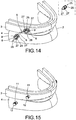
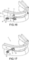
- FIG. 14 to 17 show an exemplary embodiment of the method for preparing the device (1) of Figure 1 .
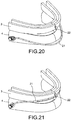
- Figures 17 to 21 show another exemplary embodiment of the method for preparing the device (20) of Figure 12 .
- the preparation method begins with a mouthpiece (2) designed for a specific patient. Initially, as shown in Figure 14 , the lower portion (4) of the mouthpiece (2) is positioned underneath the upper portion (3) and slightly forward with respect to the upper portion (3) in accordance with the treatment position previously established by the doctor or other applicable person. Then, the strap (5) is placed in a position as far back as possible (normally so that the slot (9) of the lower connector (8) is positioned in the area of the premolar teeth and the slot (9) of the upper connector (8) is positioned in the area of the canine teeth). Then, a guide part (25) is inserted in each slot (9) of the strap (5).
- the guide part (25) which has been drawn alone for informative purposes in a separate box on the upper right-hand side of the figure, is a piece with a certain thickness that has an external contour (26) that adapts to the shape of the slot (9) of the strap (5) in accordance with the invention, and that has a through hole (27) in at least one of its two ends.
- the guide part (25) must be inserted in such a way that one through hole (27) is placed in the outermost end of the slot (9). Since the guide parts (25) in the figure present a through hole (27) at each end, they can be inserted indistinctively in one direction or the other (turned 180°), facilitating the assembly process.
- a point (28) is inserted in the endmost through hole (27) of each guide part (25), i.e., in the through hole (25) that is farthest away from the body (6) of the strap (5).
- the points (28) are used to mark the respective drilling points in the upper portion (3) and the lower portion (4) of the mouthpiece (2).
- the points (28), the guide parts (25) and the strap (5) are removed and the marked points are drilled, forming respective small holes in the upper portion (3) and the lower portion (4).
- a pin is placed in each of the small drilled holes and glued with resin.
- the pins provide a protruding cylindrical portion (11) ending in a wider head (12).
- the strap (5) is positioned by first inserting one pin in one slot (9) and then inserting the other pin in the other slot (9) of the strap (5).
- the same process is carried out on the other side of the mouthpiece (2) to position a second strap (5).
- the mandibular advancement device (1) of Figure 1 is obtained.
- the preparation method once again begins with a mouthpiece (2) designed for a certain patient.
- a pin is first of all placed in one of the lateral areas (4b) of the lower portion (4), as far back as possible (normally in the molar teeth or even behind the last tooth).
- This pin provides a cylindrical portion (11) to hook the strap (21).
- Another pin is also placed in the front area (3a) of the upper portion (3), whereby this second pin provides a hook (22).
- the strap (21) is hooked in the pin as shown in Figure 19
- the strap (21) is extended towards the opposite lateral area (4b) as shown in Figure 20
- the strap (21) is hooked to the upper central pin as shown in Figure 21 .
- a kit for mandibular advancement treatment may comprise at least one strap (5; 21) and at least one guide part (25).
Landscapes
- Health & Medical Sciences (AREA)
- Life Sciences & Earth Sciences (AREA)
- Veterinary Medicine (AREA)
- Public Health (AREA)
- General Health & Medical Sciences (AREA)
- Animal Behavior & Ethology (AREA)
- Dentistry (AREA)
- Oral & Maxillofacial Surgery (AREA)
- Epidemiology (AREA)
- Engineering & Computer Science (AREA)
- Heart & Thoracic Surgery (AREA)
- Orthopedic Medicine & Surgery (AREA)
- Nursing (AREA)
- Pulmonology (AREA)
- Biomedical Technology (AREA)
- Otolaryngology (AREA)
- Vascular Medicine (AREA)
- Orthopedics, Nursing, And Contraception (AREA)
- Dental Preparations (AREA)
- Surgical Instruments (AREA)
Claims (11)
- Mandibuläre Vorschubvorrichtung (1; 20), die ein Mundstück (2) umfasst, das aus ein oberes Teil (3) und ein unteres Teil (4) hergestellt ist, wobei jedes Teil einen vorderen Bereich (3a, 4a) aufweist, der vorgesehen ist in dem Bereich der Schneide- und Eckzähne eines Anwenders angeordnet zu werden, und zwei seitliche Bereiche (3b, 4b) aufweist, die vorgesehen sind in dem Bereich der prämolaren und molaren Zähne des Anwenders angeordnet zu werden, umfassend:- mindestens einen Kunststoffstreifen (5; 21) mit zwei Enden (7), wobei jedes Ende (7) mit einem Schlitz (9) ausgestattet ist, das durch Gelenk mit einem jeweiligen zylindrischen Abschnitt (11) von einem Überstand (10) verbunden ist, der von dem Mundstück (2) seitlich hervorsteht, wobei- der Schlitz (9) geschlossen ist und von einer größeren Länge als der Durchmesser des zylindrischen Abschnitts (11) ist, so dass der zylindrische Abschnitt (11) sich durchgehend im Schlitz (9) bewegen kann, wobei- der Streifen (5; 21) angepasst ist, um durch Zug zwischen den zylindrischen Abschnitten (11) des Mundstücks (2) zu wirken, um eine freie Rückkehr des unteren Teils (4) mit Bezug auf das obere Teil (3) zu verhindern, und weiterhin wobei- der Streifen (5; 21) in Form von einem länglichen Körper (6) vorliegt, ausgestattet mit zwei Verbindern (8) an beiden Enden (7), in denen die jeweiligen Schlitze (9) angeordnet sind, dadurch gekennzeichnet, dass- der Körper (6) gebogen ist und der Streifen (5; 21) durch ein Auswärtsziehen an mindestens einem der zwei Enden (7) davon flexibel und elastisch streckbar ist, wobei eine Zugkraft, ausgeübt durch den Streifen (5; 21) an den zwei Enden (7), allmählich zunimmt, wobei die Krümmung des Körpers (6) verschwindet und der Streifen (5; 21) sich allmählich streckt.
- Vorrichtung (1) nach Anspruch 1, dadurch gekennzeichnet, dass sie zwei Streifen (5) umfasst, einen an jeder Seite des Mundstücks (2), wobei an jedem Streifen (5) ein Schlitz (9) durch Gelenk mit einem Überstand (10) verbunden ist, der von dem seitlichen Bereich (4b) des unteren Teils (4) hervorsteht und der andere Schlitz (9) durch Gelenk mit einem Überstand (10) verbunden ist, der von dem seitlichen Bereich (3b) des oberen Teils (3) hervosteht.
- Vorrichtung (20) nach Anspruch 1, dadurch gekennzeichnet, dass sie einen einzelnen Streifen (21) enthält, wobei ein Schlitz (9) des Streifens (21) durch Gelenk mit einem Überstand (10) verbunden ist, der von dem seitlichen Bereich (4b) des unteren Teils (4) hervorsteht und der andere Schlitz (9) des Streifens (21) durch Gelenk mit einem Überstand (10) verbunden ist, der von dem entgegengesetzten seitlichen Bereich (4b) des unteren Teils (4) hervorsteht.
- Vorrichtung (20) nach Anspruch 3, dadurch gekennzeichnet, dass der vordere Bereich (3a) des oberen Teils (3) mindestens einen Haken (22) umfasst, der die freie seitliche Bewegung des Streifens (21) mit Bezug auf das obere Teil (3) erlaubt und der den Streifen (21) daran hindert, sich längs von dem oberen Teil (3) zu trennen.
- Vorrichtung (1; 20) nach Anspruch 1, dadurch gekennzeichnet, dass die Verbinder (8) eine geschlossene Schlaufe mit zwei geraden seitlichen Abschnitten (13) und zwei gebogenen Endabschnitten (14) umfassen.
- Vorrichtung (1) nach Anspruch 5, dadurch gekennzeichnet, dass die seitlichen Abschnitte (13) parallel sind.
- Vorrichtung (1) nach Anspruch 5, dadurch gekennzeichnet, dass die seitlichen Abschnitte (13) zum Körper hin (6) zusammenlaufen.
- Vorrichtung (1) nach Anspruch 5, dadurch gekennzeichnet, dass der Endabschnitt (14) der Verbinder (8) eine zylindrische Innenwand (14a) aufweist, die angepasst ist um mit dem zylindrischen Abschnitt (11) des Überstands (10) in Kontakt zu kommen.
- Vorrichtung (1) nach Anspruch 5, dadurch gekennzeichnet, dass der Körper (6) eine einzelne Schnur ist.
- Vorrichtung (1) nach Anspruch 5, dadurch gekennzeichnet, dass der Körper (6) entlang einer Richtung (15) mit mindestens einer Biegung angeordnet ist.
- Vorrichtung (1) nach Anspruch 1, dadurch gekennzeichnet, dass jeder Schlitz (9) mindestens eine Verengung (16) aufweist, die in der Lage ist, der Bewegung des zylindrischen Abschnitts (11) des Überstands (10) entlang des Schlitzes (9) Widerstand zu bieten.
Priority Applications (1)
| Application Number | Priority Date | Filing Date | Title |
|---|---|---|---|
| PL15707404T PL3103420T3 (pl) | 2014-02-06 | 2015-01-30 | Urządzenie do wysuwania żuchwy |
Applications Claiming Priority (2)
| Application Number | Priority Date | Filing Date | Title |
|---|---|---|---|
| ES201400094A ES2542577B1 (es) | 2014-02-06 | 2014-02-06 | Dispositivo de avance mandibular, y método y kit de preparación de dicho dispositivo |
| PCT/ES2015/070065 WO2015118201A1 (es) | 2014-02-06 | 2015-01-30 | Dispositivo de avance mandibular, y método y kit de preparación de dicho dispositivo |
Publications (2)
| Publication Number | Publication Date |
|---|---|
| EP3103420A1 EP3103420A1 (de) | 2016-12-14 |
| EP3103420B1 true EP3103420B1 (de) | 2017-11-08 |
Family
ID=52597008
Family Applications (1)
| Application Number | Title | Priority Date | Filing Date |
|---|---|---|---|
| EP15707404.8A Active EP3103420B1 (de) | 2014-02-06 | 2015-01-30 | Mandibuläre vorschubvorrichtung |
Country Status (13)
| Country | Link |
|---|---|
| US (1) | US20150216716A1 (de) |
| EP (1) | EP3103420B1 (de) |
| JP (1) | JP6599879B2 (de) |
| KR (1) | KR20160119094A (de) |
| CA (1) | CA2937716A1 (de) |
| ES (2) | ES2542577B1 (de) |
| MX (1) | MX375602B (de) |
| NO (1) | NO3103420T3 (de) |
| PL (1) | PL3103420T3 (de) |
| PT (1) | PT3103420T (de) |
| RU (1) | RU2703505C2 (de) |
| TW (1) | TWI650110B (de) |
| WO (1) | WO2015118201A1 (de) |
Cited By (1)
| Publication number | Priority date | Publication date | Assignee | Title |
|---|---|---|---|---|
| US12097120B2 (en) | 2022-03-07 | 2024-09-24 | Sleep Mechanics Llc | Bone implant device |
Families Citing this family (78)
| Publication number | Priority date | Publication date | Assignee | Title |
|---|---|---|---|---|
| US9675427B2 (en) * | 2013-06-07 | 2017-06-13 | Align Technology, Inc. | Adjusting a tooth position |
| US12213906B2 (en) | 2013-07-01 | 2025-02-04 | R. Joseph Magness | Dental appliance for treatment of sleep apnea |
| US10449016B2 (en) | 2014-09-19 | 2019-10-22 | Align Technology, Inc. | Arch adjustment appliance |
| US9610141B2 (en) | 2014-09-19 | 2017-04-04 | Align Technology, Inc. | Arch expanding appliance |
| US10504386B2 (en) | 2015-01-27 | 2019-12-10 | Align Technology, Inc. | Training method and system for oral-cavity-imaging-and-modeling equipment |
| AU2015101689B4 (en) * | 2015-03-20 | 2016-04-28 | Lambert, Geoffrey James MR | Mandibular reposition device and coupling therefor |
| USD777931S1 (en) * | 2015-05-28 | 2017-01-31 | Respire Medical Holdings, LLC | Oral dental appliance |
| KR101722640B1 (ko) * | 2015-10-13 | 2017-04-03 | 서울대학교산학협력단 | 하악 전진 장치 |
| US11554000B2 (en) | 2015-11-12 | 2023-01-17 | Align Technology, Inc. | Dental attachment formation structure |
| US11931222B2 (en) | 2015-11-12 | 2024-03-19 | Align Technology, Inc. | Dental attachment formation structures |
| US11103330B2 (en) | 2015-12-09 | 2021-08-31 | Align Technology, Inc. | Dental attachment placement structure |
| US11596502B2 (en) | 2015-12-09 | 2023-03-07 | Align Technology, Inc. | Dental attachment placement structure |
| EP3427704B1 (de) | 2016-03-08 | 2021-04-07 | Mitsui Chemicals, Inc. | Mundstück |
| US10265213B2 (en) * | 2016-03-25 | 2019-04-23 | Jae Il Lim | Temporomandibular joint correction apparatus with exchangeable adjustor |
| US20170360595A1 (en) * | 2016-05-18 | 2017-12-21 | Jacob Smith | Intraoral Orthosis for Mandibular Advancement for Snoring and Obstructive Sleep Apnea |
| EP4670634A3 (de) | 2016-06-17 | 2026-01-21 | Align Technology, Inc. | System zur bestimmung der patientenkonformität mit einem orthodontischen behandlungs- oder retentionsplan |
| EP3471653B1 (de) | 2016-06-17 | 2021-12-22 | Align Technology, Inc. | Leistungsüberwachung einer kieferorthopädischen vorrichtung |
| US10507087B2 (en) | 2016-07-27 | 2019-12-17 | Align Technology, Inc. | Methods and apparatuses for forming a three-dimensional volumetric model of a subject's teeth |
| EP4252698B1 (de) | 2016-07-27 | 2025-04-30 | Align Technology, Inc. | Intraoraler scanner mit zahnmedizinischen diagnosefähigkeiten |
| CN106473851A (zh) * | 2016-07-28 | 2017-03-08 | 姜晓蕾 | 一种医用口腔矫正磨牙装置 |
| EP3824843B1 (de) | 2016-12-02 | 2024-12-25 | Align Technology, Inc. | Serie von palatalen expandern |
| CA3043049A1 (en) | 2016-12-02 | 2018-06-07 | Align Technology, Inc. | Methods and apparatuses for customizing rapid palatal expanders using digital models |
| US11026831B2 (en) | 2016-12-02 | 2021-06-08 | Align Technology, Inc. | Dental appliance features for speech enhancement |
| WO2018102770A1 (en) | 2016-12-02 | 2018-06-07 | Align Technology, Inc. | Force control, stop mechanism, regulating structure of removable arch adjustment appliance |
| US10548700B2 (en) | 2016-12-16 | 2020-02-04 | Align Technology, Inc. | Dental appliance etch template |
| US10779718B2 (en) | 2017-02-13 | 2020-09-22 | Align Technology, Inc. | Cheek retractor and mobile device holder |
| DE102017103722A1 (de) | 2017-02-23 | 2018-08-23 | Hicat Gmbh | Unterkiefer-Protrusionsschiene |
| WO2018183358A1 (en) | 2017-03-27 | 2018-10-04 | Align Technology, Inc. | Apparatuses and methods assisting in dental therapies |
| FR3064465A1 (fr) * | 2017-03-30 | 2018-10-05 | Stephan Valero | Activateur de croissance dento-maxilo-faciale |
| US10613515B2 (en) | 2017-03-31 | 2020-04-07 | Align Technology, Inc. | Orthodontic appliances including at least partially un-erupted teeth and method of forming them |
| KR101959537B1 (ko) * | 2017-04-21 | 2019-03-18 | 남관우 | 코골이 방지용 하악골 전방 견인 장치 |
| US12138198B2 (en) | 2017-05-26 | 2024-11-12 | Diamond Orthotic Laboratory, Llc | Oral appliance device |
| US11045283B2 (en) | 2017-06-09 | 2021-06-29 | Align Technology, Inc. | Palatal expander with skeletal anchorage devices |
| DE102017113833A1 (de) | 2017-06-22 | 2018-12-27 | Konrad Hofmann | Okklusionsschienenanordnung mit Fixierband |
| WO2019005808A1 (en) | 2017-06-26 | 2019-01-03 | Align Technology, Inc. | BIOCAPTOR PERFORMANCE INDICATOR FOR INTRABUCCAL DEVICES |
| AU2018299419B2 (en) * | 2017-07-11 | 2023-05-18 | Stewart Cullen | Mandibular advancement splint |
| US10885521B2 (en) | 2017-07-17 | 2021-01-05 | Align Technology, Inc. | Method and apparatuses for interactive ordering of dental aligners |
| CN111107806B (zh) | 2017-07-21 | 2022-04-19 | 阿莱恩技术有限公司 | 颚轮廓锚固 |
| US11633268B2 (en) | 2017-07-27 | 2023-04-25 | Align Technology, Inc. | Tooth shading, transparency and glazing |
| US12274597B2 (en) | 2017-08-11 | 2025-04-15 | Align Technology, Inc. | Dental attachment template tray systems |
| WO2019035979A1 (en) | 2017-08-15 | 2019-02-21 | Align Technology, Inc. | EVALUATION AND CALCULATION OF BUCCAL CORRIDOR |
| WO2019036677A1 (en) | 2017-08-17 | 2019-02-21 | Align Technology, Inc. | SURVEILLANCE OF CONFORMITY OF DENTAL DEVICE |
| WO2019071019A1 (en) | 2017-10-04 | 2019-04-11 | Align Technology, Inc. | INTRAORAL APPARATUS FOR SAMPLING MOUTH TISSUE |
| US10813720B2 (en) | 2017-10-05 | 2020-10-27 | Align Technology, Inc. | Interproximal reduction templates |
| EP3700458B1 (de) | 2017-10-27 | 2023-06-07 | Align Technology, Inc. | Alternative bisseinstellungsstrukturen |
| CN111295153B (zh) | 2017-10-31 | 2023-06-16 | 阿莱恩技术有限公司 | 具有选择性牙合负荷和受控牙尖交错的牙科器具 |
| WO2019089989A2 (en) | 2017-11-01 | 2019-05-09 | Align Technology, Inc. | Automatic treatment planning |
| WO2019100022A1 (en) | 2017-11-17 | 2019-05-23 | Align Technology, Inc. | Orthodontic retainers |
| EP3716885B1 (de) | 2017-11-30 | 2023-08-30 | Align Technology, Inc. | Sensoren umfassende orthodontische intraorale geräte |
| US11432908B2 (en) | 2017-12-15 | 2022-09-06 | Align Technology, Inc. | Closed loop adaptive orthodontic treatment methods and apparatuses |
| US10980613B2 (en) | 2017-12-29 | 2021-04-20 | Align Technology, Inc. | Augmented reality enhancements for dental practitioners |
| KR20200115580A (ko) | 2018-01-26 | 2020-10-07 | 얼라인 테크널러지, 인크. | 구강 내 진단 스캔 및 추적 |
| EP3746014B1 (de) * | 2018-01-31 | 2023-05-24 | Odin Sleep, LLC | Orale schlafapnoe-vorrichtung mit konnektoren |
| ZAF201800180S (en) * | 2018-02-07 | 2019-05-29 | Brauteseth Leif Trygvar | Mandibular advancement device |
| US11937991B2 (en) | 2018-03-27 | 2024-03-26 | Align Technology, Inc. | Dental attachment placement structure |
| WO2019200008A1 (en) | 2018-04-11 | 2019-10-17 | Align Technology, Inc. | Releasable palatal expanders |
| USD888249S1 (en) * | 2019-01-15 | 2020-06-23 | Ryan Bruss | Mouthguard |
| US11259955B2 (en) | 2019-05-29 | 2022-03-01 | Pankaj Pal Singh | Apparatus and methods to convert dental, oral, orthodontic appliances, retainers, and dentures into a multifunctional oral appliance |
| ES2803098A1 (es) * | 2019-07-22 | 2021-01-22 | Diez Ana Belen Martinez | Dispositivo avance mandibular |
| WO2021054133A1 (ja) * | 2019-09-19 | 2021-03-25 | 三井化学株式会社 | マウスピース |
| WO2021119533A1 (en) * | 2019-12-12 | 2021-06-17 | ProSomnus Sleep Technologies, Inc. | Liners for a mandibular advancement device |
| USD970013S1 (en) * | 2020-01-27 | 2022-11-15 | Frantz Design Incorporated | Mandibular advancement appliance |
| USD983975S1 (en) * | 2020-02-27 | 2023-04-18 | Mitsui Chemicals, Inc. | Hinge for oral sleep appliance |
| USD977652S1 (en) * | 2020-07-15 | 2023-02-07 | Peacefulsleep Pty Ltd | Mandibular advancement device |
| USD970012S1 (en) | 2020-08-27 | 2022-11-15 | Mitsui Chemicals, Inc. | Oral sleep apnea appliance |
| US12616605B2 (en) * | 2020-12-22 | 2026-05-05 | James R. Glidewell Dental Ceramics, Inc. | Mandibular repositioning device |
| US12544193B2 (en) * | 2020-12-23 | 2026-02-10 | Ortho Organizers, Inc. | Orthodontic appliance and method of use |
| USD1042848S1 (en) | 2020-12-23 | 2024-09-17 | James R. Glidewell Dental Ceramics, Inc. | Dental appliance connecting arm |
| EA039297B1 (ru) * | 2020-12-30 | 2021-12-30 | Республиканское Инновационное Унитарное Предприятие "Научно-Технологический Парк Бнту "Политехник" | Устройство интраоральное стоматологическое |
| CA3223110A1 (en) * | 2021-06-16 | 2022-12-22 | Caner Karaceper | System, kit and process for diagnosis and treatment of obstructive sleep apnea using oral appliance therapy |
| USD1001289S1 (en) * | 2021-09-10 | 2023-10-10 | Sahereh Mohammadi | Centric relation self registering full denture oral appliance for direct mounting on laboratory articulator |
| USD1001288S1 (en) * | 2021-09-10 | 2023-10-10 | Fariba Moeinipour Maraghi | Passive snore-sensitive mandibular protrusion optimizer oral appliance for obstructive sleep apnea prevention |
| US20220287871A1 (en) * | 2022-05-26 | 2022-09-15 | Caner Karaceper | Snoring and obstructive sleep apnea prevention device |
| NL2032973B1 (en) * | 2022-09-07 | 2024-03-21 | Michiel Allessie Holding B V | Mandibular repositioning appliance |
| EP4731140A2 (de) * | 2023-06-21 | 2026-04-29 | Frantz, Donald | Dentale geräteanordnung zur steuerung des vormandibulären vorschubs |
| USD1116119S1 (en) * | 2023-06-28 | 2026-03-03 | George Stott Boshoff | Mandibular advancement device |
| WO2025166243A1 (en) * | 2024-01-31 | 2025-08-07 | Achaemenid, Llc | Apparatus for invisible tooth alignment with ortho strut for sleep apnea |
| CA3267866A1 (en) * | 2024-08-06 | 2026-03-01 | Xingchen Liu | Snoring and obstructive sleep apnea prevention device |
Family Cites Families (28)
| Publication number | Priority date | Publication date | Assignee | Title |
|---|---|---|---|---|
| US4382783A (en) * | 1982-06-28 | 1983-05-10 | Rosenberg Farel A | Intraoral dental appliance to correct retrusive mandibles orthopedically in the treatment of Class II malocclusions |
| US4708646A (en) * | 1986-04-01 | 1987-11-24 | Jasper James J | Orthodontic device for correcting the bite |
| US5074784A (en) * | 1989-10-24 | 1991-12-24 | Ormco Corporation | Orthodontic assembly |
| US5120218A (en) * | 1991-05-13 | 1992-06-09 | Hanson G Herbert | Orthodontic traction devices |
| US6109265A (en) * | 1995-06-23 | 2000-08-29 | Frantz; Don E. | Elastic mandibular advancement appliance |
| US5697782A (en) * | 1996-05-09 | 1997-12-16 | Klapper; Lewis | Orthodontic device and method for correcting overbite and underbite |
| US6325064B1 (en) * | 1999-09-15 | 2001-12-04 | W. Keith Thornton | Device for improving breathing and method of fitting same |
| US6488498B1 (en) * | 2000-09-01 | 2002-12-03 | Richard C. Mariani, Jr. | Elastic orthodontic component |
| US6935858B2 (en) * | 2002-11-19 | 2005-08-30 | 3M Innovative Properties Company | Elastomeric force module for orthodontic treatment |
| JP2006095245A (ja) * | 2004-08-31 | 2006-04-13 | Masato Ueno | 無呼吸症候群又はいびき症改善用のマウスピース |
| US7070410B2 (en) * | 2004-09-02 | 2006-07-04 | Cacchiotti Dino A | Orthodontic device for attachment to orthodontic wire |
| EP1658823A1 (de) * | 2004-11-23 | 2006-05-24 | Michel Valceschini | Zahnärztliche Vorrichtung zur Korrektur der Position des Unterkiefers |
| JP4998958B2 (ja) * | 2006-08-25 | 2012-08-15 | 国立大学法人 長崎大学 | 睡眠時無呼吸症候群又はいびき症改善下顎前方位型口腔内装置用コネクター |
| WO2008048649A2 (en) * | 2006-10-18 | 2008-04-24 | Sheri Katz | Mouth-closing device for sleep disorder treatments |
| US20090032030A1 (en) * | 2007-07-30 | 2009-02-05 | Callender R Sam | Apparatus for treatment of sleep apnea |
| US20090056725A1 (en) * | 2007-08-29 | 2009-03-05 | Farnaz Zand | Protective guards and method of using same |
| DE102008007281A1 (de) * | 2008-02-02 | 2009-08-06 | Rainer Hamann | Infraorales Therapiegerät |
| FR2933603B1 (fr) * | 2008-07-10 | 2012-03-16 | Gerard Vincent | Bielle pour arcades dentaires et dispositifs d'attache des bielles |
| DE202008011841U1 (de) * | 2008-09-06 | 2008-11-13 | Toussaint, Winfried, Dr. | Verstellbare Unterkieferprotrusionsschiene zur Behandlung von Schnarchen und obstruktiver Schlafapnoe |
| DE202008016373U1 (de) * | 2008-10-17 | 2009-03-12 | Dr. Hinz-Labor Fachlaboratorium für Kieferorthopädie GmbH & Co. KG | Vorschubstab für ein intraorales Therapiegerät |
| US8062032B2 (en) * | 2008-10-23 | 2011-11-22 | Intrinsic Medical, Llc | Apparatus, system, and method for maxillo-mandibular fixation |
| CN201422945Y (zh) * | 2009-05-27 | 2010-03-17 | 山东大学 | 一种可调型下颌前置式osahs治疗器 |
| FR2964853B1 (fr) * | 2010-09-22 | 2013-10-04 | Tali | Gouttieres dentaires a bielles de liaison articulees sur pivots |
| DE102010046369B4 (de) * | 2010-09-24 | 2013-01-24 | Erkodent Erich Kopp Gmbh | Antischnarchvorrichtung |
| US9615964B2 (en) * | 2011-09-30 | 2017-04-11 | American Dental Sleep Medicine Ip, Llc | Methods and oral orthotic systems for use in connection with sleep-disordered breathing |
| US20140020691A1 (en) * | 2012-07-18 | 2014-01-23 | Rest Assured Technologies | Oral appliance for treatment of medical conditions such as obstructive sleep apnea and snoring and for improving athletic performance and method of optimizing same |
| USD720857S1 (en) * | 2012-11-21 | 2015-01-06 | Giuseppe Burlon | Double eyebolt for dental protrusor |
| USD720858S1 (en) * | 2012-11-21 | 2015-01-06 | Giuseppe Burlon | Dental protrusor |
-
2014
- 2014-02-06 ES ES201400094A patent/ES2542577B1/es not_active Expired - Fee Related
-
2015
- 2015-01-30 KR KR1020167021461A patent/KR20160119094A/ko not_active Ceased
- 2015-01-30 MX MX2016008694A patent/MX375602B/es active IP Right Grant
- 2015-01-30 CA CA2937716A patent/CA2937716A1/en not_active Abandoned
- 2015-01-30 EP EP15707404.8A patent/EP3103420B1/de active Active
- 2015-01-30 ES ES15707404.8T patent/ES2657446T3/es active Active
- 2015-01-30 PL PL15707404T patent/PL3103420T3/pl unknown
- 2015-01-30 RU RU2016135534A patent/RU2703505C2/ru not_active IP Right Cessation
- 2015-01-30 JP JP2016549162A patent/JP6599879B2/ja active Active
- 2015-01-30 WO PCT/ES2015/070065 patent/WO2015118201A1/es not_active Ceased
- 2015-01-30 NO NO15707404A patent/NO3103420T3/no unknown
- 2015-01-30 PT PT157074048T patent/PT3103420T/pt unknown
- 2015-02-03 TW TW104103540A patent/TWI650110B/zh not_active IP Right Cessation
- 2015-02-06 US US14/615,740 patent/US20150216716A1/en not_active Abandoned
Non-Patent Citations (1)
| Title |
|---|
| None * |
Cited By (1)
| Publication number | Priority date | Publication date | Assignee | Title |
|---|---|---|---|---|
| US12097120B2 (en) | 2022-03-07 | 2024-09-24 | Sleep Mechanics Llc | Bone implant device |
Also Published As
| Publication number | Publication date |
|---|---|
| US20150216716A1 (en) | 2015-08-06 |
| MX2016008694A (es) | 2016-09-08 |
| KR20160119094A (ko) | 2016-10-12 |
| JP2017505179A (ja) | 2017-02-16 |
| PT3103420T (pt) | 2018-01-24 |
| TW201534286A (zh) | 2015-09-16 |
| PL3103420T3 (pl) | 2018-03-30 |
| EP3103420A1 (de) | 2016-12-14 |
| ES2542577A1 (es) | 2015-08-06 |
| ES2657446T3 (es) | 2018-03-05 |
| CA2937716A1 (en) | 2015-08-13 |
| TWI650110B (zh) | 2019-02-11 |
| MX375602B (es) | 2025-03-06 |
| NO3103420T3 (de) | 2018-04-07 |
| RU2016135534A3 (de) | 2018-06-29 |
| JP6599879B2 (ja) | 2019-10-30 |
| RU2703505C2 (ru) | 2019-10-17 |
| WO2015118201A1 (es) | 2015-08-13 |
| RU2016135534A (ru) | 2018-03-14 |
| ES2542577B1 (es) | 2016-09-12 |
Similar Documents
| Publication | Publication Date | Title |
|---|---|---|
| US20150216716A1 (en) | Mandibular advancement device, and a method and kit for preparing said device | |
| CN109789000B (zh) | 与气道发育疗法组合的牙齿正畸移动 | |
| EP3297586B1 (de) | Orales gerät | |
| US10959875B2 (en) | Masticatory and airway stabilizing orthotic, and associated systems and methods | |
| US20140072927A1 (en) | Adjustable mandibular advancement device | |
| KR101782093B1 (ko) | 코골이 및 이갈이 방지기구 | |
| US20080210244A1 (en) | Sleep appliance | |
| KR102058104B1 (ko) | 하악의 유동성과 치아의 고정성을 개선한 구강 장치 | |
| US20150272773A1 (en) | Intraoral apparatus for managing snoring and obstructive sleep apnea | |
| US20170151086A1 (en) | Custom made oral appliance for airway management of those with obstructive sleep apnea (osa) | |
| WO2007136551A2 (en) | Sleep appliance | |
| EP2882384B1 (de) | Intraorale funktionale vorrichtung zur linderung von obstruktiver schlafapnoe, schnarchen bzw. anderen atemwegsstörungen | |
| KR101990318B1 (ko) | 이탈방지 및 턱관절 운동이 가능한 이갈이 및 코골이 완화 기구 | |
| US9492310B2 (en) | Adjustable tongue retaining oral appliance | |
| WO2002071989A1 (en) | Appliances for treating sleep apnoea | |
| EP2380533B1 (de) | Intraorale schiene | |
| US11679023B2 (en) | Mandibular advancement splint | |
| KR102845596B1 (ko) | 코골이완화 및 수면무호흡 방지용 상하악 교합위치 미세조정형 기도 확장기 | |
| KR20180025676A (ko) | 코골이 및 이갈이 방지 기구 | |
| WO2014197430A1 (en) | Elastic pull oral appliance and methods of treating sleep apnea and snoring while concurrently preventing or reducing the risk of tmj | |
| KR20150119609A (ko) | 수면 호흡장애 치료용 구강장치 | |
| AU2023242795B2 (en) | Improvements to dental splints for treatment of snoring or sleep apnoea | |
| AU2020461645B2 (en) | Mandible adjusting device | |
| KR102830977B1 (ko) | 하악 변위 조절장치 | |
| HK40005111A (en) | Combined orthodontic movement of teeth with airway development therapy |
Legal Events
| Date | Code | Title | Description |
|---|---|---|---|
| PUAI | Public reference made under article 153(3) epc to a published international application that has entered the european phase |
Free format text: ORIGINAL CODE: 0009012 |
|
| 17P | Request for examination filed |
Effective date: 20160718 |
|
| AK | Designated contracting states |
Kind code of ref document: A1 Designated state(s): AL AT BE BG CH CY CZ DE DK EE ES FI FR GB GR HR HU IE IS IT LI LT LU LV MC MK MT NL NO PL PT RO RS SE SI SK SM TR |
|
| AX | Request for extension of the european patent |
Extension state: BA ME |
|
| DAX | Request for extension of the european patent (deleted) | ||
| GRAP | Despatch of communication of intention to grant a patent |
Free format text: ORIGINAL CODE: EPIDOSNIGR1 |
|
| INTG | Intention to grant announced |
Effective date: 20170704 |
|
| GRAS | Grant fee paid |
Free format text: ORIGINAL CODE: EPIDOSNIGR3 |
|
| GRAA | (expected) grant |
Free format text: ORIGINAL CODE: 0009210 |
|
| RAP1 | Party data changed (applicant data changed or rights of an application transferred) |
Owner name: BIOTECHNOLOGY INSTITUTE, I MAS D, S.L. |
|
| AK | Designated contracting states |
Kind code of ref document: B1 Designated state(s): AL AT BE BG CH CY CZ DE DK EE ES FI FR GB GR HR HU IE IS IT LI LT LU LV MC MK MT NL NO PL PT RO RS SE SI SK SM TR |
|
| REG | Reference to a national code |
Ref country code: GB Ref legal event code: FG4D |
|
| REG | Reference to a national code |
Ref country code: AT Ref legal event code: REF Ref document number: 943437 Country of ref document: AT Kind code of ref document: T Effective date: 20171115 Ref country code: CH Ref legal event code: EP |
|
| REG | Reference to a national code |
Ref country code: IE Ref legal event code: FG4D |
|
| REG | Reference to a national code |
Ref country code: DE Ref legal event code: R096 Ref document number: 602015005889 Country of ref document: DE |
|
| REG | Reference to a national code |
Ref country code: PT Ref legal event code: SC4A Ref document number: 3103420 Country of ref document: PT Date of ref document: 20180124 Kind code of ref document: T Free format text: AVAILABILITY OF NATIONAL TRANSLATION Effective date: 20180117 Ref country code: NL Ref legal event code: FP |
|
| REG | Reference to a national code |
Ref country code: FR Ref legal event code: PLFP Year of fee payment: 4 |
|
| REG | Reference to a national code |
Ref country code: SE Ref legal event code: TRGR |
|
| REG | Reference to a national code |
Ref country code: NO Ref legal event code: T2 Effective date: 20171108 Ref country code: ES Ref legal event code: FG2A Ref document number: 2657446 Country of ref document: ES Kind code of ref document: T3 Effective date: 20180305 |
|
| REG | Reference to a national code |
Ref country code: LT Ref legal event code: MG4D |
|
| PG25 | Lapsed in a contracting state [announced via postgrant information from national office to epo] |
Ref country code: LT Free format text: LAPSE BECAUSE OF FAILURE TO SUBMIT A TRANSLATION OF THE DESCRIPTION OR TO PAY THE FEE WITHIN THE PRESCRIBED TIME-LIMIT Effective date: 20171108 |
|
| PG25 | Lapsed in a contracting state [announced via postgrant information from national office to epo] |
Ref country code: LV Free format text: LAPSE BECAUSE OF FAILURE TO SUBMIT A TRANSLATION OF THE DESCRIPTION OR TO PAY THE FEE WITHIN THE PRESCRIBED TIME-LIMIT Effective date: 20171108 Ref country code: RS Free format text: LAPSE BECAUSE OF FAILURE TO SUBMIT A TRANSLATION OF THE DESCRIPTION OR TO PAY THE FEE WITHIN THE PRESCRIBED TIME-LIMIT Effective date: 20171108 Ref country code: HR Free format text: LAPSE BECAUSE OF FAILURE TO SUBMIT A TRANSLATION OF THE DESCRIPTION OR TO PAY THE FEE WITHIN THE PRESCRIBED TIME-LIMIT Effective date: 20171108 Ref country code: BG Free format text: LAPSE BECAUSE OF FAILURE TO SUBMIT A TRANSLATION OF THE DESCRIPTION OR TO PAY THE FEE WITHIN THE PRESCRIBED TIME-LIMIT Effective date: 20180208 Ref country code: IS Free format text: LAPSE BECAUSE OF FAILURE TO SUBMIT A TRANSLATION OF THE DESCRIPTION OR TO PAY THE FEE WITHIN THE PRESCRIBED TIME-LIMIT Effective date: 20180308 |
|
| REG | Reference to a national code |
Ref country code: GR Ref legal event code: EP Ref document number: 20180400045 Country of ref document: GR Effective date: 20180518 |
|
| PG25 | Lapsed in a contracting state [announced via postgrant information from national office to epo] |
Ref country code: SK Free format text: LAPSE BECAUSE OF FAILURE TO SUBMIT A TRANSLATION OF THE DESCRIPTION OR TO PAY THE FEE WITHIN THE PRESCRIBED TIME-LIMIT Effective date: 20171108 Ref country code: CZ Free format text: LAPSE BECAUSE OF FAILURE TO SUBMIT A TRANSLATION OF THE DESCRIPTION OR TO PAY THE FEE WITHIN THE PRESCRIBED TIME-LIMIT Effective date: 20171108 Ref country code: DK Free format text: LAPSE BECAUSE OF FAILURE TO SUBMIT A TRANSLATION OF THE DESCRIPTION OR TO PAY THE FEE WITHIN THE PRESCRIBED TIME-LIMIT Effective date: 20171108 Ref country code: CY Free format text: LAPSE BECAUSE OF FAILURE TO SUBMIT A TRANSLATION OF THE DESCRIPTION OR TO PAY THE FEE WITHIN THE PRESCRIBED TIME-LIMIT Effective date: 20171108 Ref country code: EE Free format text: LAPSE BECAUSE OF FAILURE TO SUBMIT A TRANSLATION OF THE DESCRIPTION OR TO PAY THE FEE WITHIN THE PRESCRIBED TIME-LIMIT Effective date: 20171108 |
|
| REG | Reference to a national code |
Ref country code: DE Ref legal event code: R097 Ref document number: 602015005889 Country of ref document: DE |
|
| PG25 | Lapsed in a contracting state [announced via postgrant information from national office to epo] |
Ref country code: RO Free format text: LAPSE BECAUSE OF FAILURE TO SUBMIT A TRANSLATION OF THE DESCRIPTION OR TO PAY THE FEE WITHIN THE PRESCRIBED TIME-LIMIT Effective date: 20171108 Ref country code: SM Free format text: LAPSE BECAUSE OF FAILURE TO SUBMIT A TRANSLATION OF THE DESCRIPTION OR TO PAY THE FEE WITHIN THE PRESCRIBED TIME-LIMIT Effective date: 20171108 |
|
| PLBE | No opposition filed within time limit |
Free format text: ORIGINAL CODE: 0009261 |
|
| 26N | No opposition filed |
Effective date: 20180809 |
|
| PG25 | Lapsed in a contracting state [announced via postgrant information from national office to epo] |
Ref country code: SI Free format text: LAPSE BECAUSE OF FAILURE TO SUBMIT A TRANSLATION OF THE DESCRIPTION OR TO PAY THE FEE WITHIN THE PRESCRIBED TIME-LIMIT Effective date: 20171108 |
|
| PG25 | Lapsed in a contracting state [announced via postgrant information from national office to epo] |
Ref country code: MC Free format text: LAPSE BECAUSE OF FAILURE TO SUBMIT A TRANSLATION OF THE DESCRIPTION OR TO PAY THE FEE WITHIN THE PRESCRIBED TIME-LIMIT Effective date: 20171108 |
|
| PLAA | Information modified related to event that no opposition was filed |
Free format text: ORIGINAL CODE: 0009299DELT |
|
| PLBE | No opposition filed within time limit |
Free format text: ORIGINAL CODE: 0009261 |
|
| R26N | No opposition filed (corrected) |
Effective date: 20180809 |
|
| PG25 | Lapsed in a contracting state [announced via postgrant information from national office to epo] |
Ref country code: MT Free format text: LAPSE BECAUSE OF NON-PAYMENT OF DUE FEES Effective date: 20180130 |
|
| REG | Reference to a national code |
Ref country code: AT Ref legal event code: UEP Ref document number: 943437 Country of ref document: AT Kind code of ref document: T Effective date: 20171108 |
|
| PGFP | Annual fee paid to national office [announced via postgrant information from national office to epo] |
Ref country code: NL Payment date: 20200126 Year of fee payment: 6 Ref country code: SE Payment date: 20200129 Year of fee payment: 6 Ref country code: PL Payment date: 20200110 Year of fee payment: 6 Ref country code: NO Payment date: 20200129 Year of fee payment: 6 Ref country code: AT Payment date: 20200102 Year of fee payment: 6 Ref country code: FI Payment date: 20200130 Year of fee payment: 6 Ref country code: GR Payment date: 20200129 Year of fee payment: 6 Ref country code: IE Payment date: 20200127 Year of fee payment: 6 |
|
| PGFP | Annual fee paid to national office [announced via postgrant information from national office to epo] |
Ref country code: BE Payment date: 20200127 Year of fee payment: 6 Ref country code: LU Payment date: 20200127 Year of fee payment: 6 Ref country code: CH Payment date: 20200131 Year of fee payment: 6 |
|
| PG25 | Lapsed in a contracting state [announced via postgrant information from national office to epo] |
Ref country code: MK Free format text: LAPSE BECAUSE OF NON-PAYMENT OF DUE FEES Effective date: 20171108 Ref country code: HU Free format text: LAPSE BECAUSE OF FAILURE TO SUBMIT A TRANSLATION OF THE DESCRIPTION OR TO PAY THE FEE WITHIN THE PRESCRIBED TIME-LIMIT; INVALID AB INITIO Effective date: 20150130 |
|
| PGFP | Annual fee paid to national office [announced via postgrant information from national office to epo] |
Ref country code: TR Payment date: 20200115 Year of fee payment: 6 |
|
| PG25 | Lapsed in a contracting state [announced via postgrant information from national office to epo] |
Ref country code: AL Free format text: LAPSE BECAUSE OF FAILURE TO SUBMIT A TRANSLATION OF THE DESCRIPTION OR TO PAY THE FEE WITHIN THE PRESCRIBED TIME-LIMIT Effective date: 20171108 |
|
| REG | Reference to a national code |
Ref country code: FI Ref legal event code: MAE |
|
| REG | Reference to a national code |
Ref country code: NO Ref legal event code: MMEP |
|
| REG | Reference to a national code |
Ref country code: CH Ref legal event code: PL Ref country code: SE Ref legal event code: EUG |
|
| REG | Reference to a national code |
Ref country code: NL Ref legal event code: MM Effective date: 20210201 |
|
| REG | Reference to a national code |
Ref country code: AT Ref legal event code: MM01 Ref document number: 943437 Country of ref document: AT Kind code of ref document: T Effective date: 20210130 |
|
| PG25 | Lapsed in a contracting state [announced via postgrant information from national office to epo] |
Ref country code: LU Free format text: LAPSE BECAUSE OF NON-PAYMENT OF DUE FEES Effective date: 20210130 |
|
| REG | Reference to a national code |
Ref country code: BE Ref legal event code: MM Effective date: 20210131 |
|
| PG25 | Lapsed in a contracting state [announced via postgrant information from national office to epo] |
Ref country code: AT Free format text: LAPSE BECAUSE OF NON-PAYMENT OF DUE FEES Effective date: 20210130 Ref country code: FI Free format text: LAPSE BECAUSE OF NON-PAYMENT OF DUE FEES Effective date: 20210130 Ref country code: NL Free format text: LAPSE BECAUSE OF NON-PAYMENT OF DUE FEES Effective date: 20210201 |
|
| PG25 | Lapsed in a contracting state [announced via postgrant information from national office to epo] |
Ref country code: GR Free format text: LAPSE BECAUSE OF NON-PAYMENT OF DUE FEES Effective date: 20210805 Ref country code: LI Free format text: LAPSE BECAUSE OF NON-PAYMENT OF DUE FEES Effective date: 20210131 Ref country code: CH Free format text: LAPSE BECAUSE OF NON-PAYMENT OF DUE FEES Effective date: 20210131 Ref country code: NO Free format text: LAPSE BECAUSE OF NON-PAYMENT OF DUE FEES Effective date: 20210131 Ref country code: SE Free format text: LAPSE BECAUSE OF NON-PAYMENT OF DUE FEES Effective date: 20210131 |
|
| PG25 | Lapsed in a contracting state [announced via postgrant information from national office to epo] |
Ref country code: IE Free format text: LAPSE BECAUSE OF NON-PAYMENT OF DUE FEES Effective date: 20210130 |
|
| PG25 | Lapsed in a contracting state [announced via postgrant information from national office to epo] |
Ref country code: TR Free format text: LAPSE BECAUSE OF NON-PAYMENT OF DUE FEES Effective date: 20210130 |
|
| PG25 | Lapsed in a contracting state [announced via postgrant information from national office to epo] |
Ref country code: BE Free format text: LAPSE BECAUSE OF NON-PAYMENT OF DUE FEES Effective date: 20210131 |
|
| PG25 | Lapsed in a contracting state [announced via postgrant information from national office to epo] |
Ref country code: PL Free format text: LAPSE BECAUSE OF NON-PAYMENT OF DUE FEES Effective date: 20210130 |
|
| P01 | Opt-out of the competence of the unified patent court (upc) registered |
Effective date: 20230605 |
|
| PGFP | Annual fee paid to national office [announced via postgrant information from national office to epo] |
Ref country code: GB Payment date: 20260127 Year of fee payment: 12 |
|
| PGFP | Annual fee paid to national office [announced via postgrant information from national office to epo] |
Ref country code: ES Payment date: 20260202 Year of fee payment: 12 |
|
| PGFP | Annual fee paid to national office [announced via postgrant information from national office to epo] |
Ref country code: DE Payment date: 20260128 Year of fee payment: 12 |
|
| PGFP | Annual fee paid to national office [announced via postgrant information from national office to epo] |
Ref country code: IT Payment date: 20260121 Year of fee payment: 12 |
|
| PGFP | Annual fee paid to national office [announced via postgrant information from national office to epo] |
Ref country code: FR Payment date: 20260126 Year of fee payment: 12 |
|
| PGFP | Annual fee paid to national office [announced via postgrant information from national office to epo] |
Ref country code: PT Payment date: 20260113 Year of fee payment: 12 |