EP3103556A1 - Aufnahmevorrichtung für längsschneidelinienschleife - Google Patents
Aufnahmevorrichtung für längsschneidelinienschleife Download PDFInfo
- Publication number
- EP3103556A1 EP3103556A1 EP14789969.4A EP14789969A EP3103556A1 EP 3103556 A1 EP3103556 A1 EP 3103556A1 EP 14789969 A EP14789969 A EP 14789969A EP 3103556 A1 EP3103556 A1 EP 3103556A1
- Authority
- EP
- European Patent Office
- Prior art keywords
- negative pressure
- loop
- strips
- slitter
- rotating body
- Prior art date
- Legal status (The legal status is an assumption and is not a legal conclusion. Google has not performed a legal analysis and makes no representation as to the accuracy of the status listed.)
- Granted
Links
Images










Classifications
-
- B—PERFORMING OPERATIONS; TRANSPORTING
- B65—CONVEYING; PACKING; STORING; HANDLING THIN OR FILAMENTARY MATERIAL
- B65H—HANDLING THIN OR FILAMENTARY MATERIAL, e.g. SHEETS, WEBS, CABLES
- B65H20/00—Advancing webs
- B65H20/12—Advancing webs by suction roller
-
- B—PERFORMING OPERATIONS; TRANSPORTING
- B21—MECHANICAL METAL-WORKING WITHOUT ESSENTIALLY REMOVING MATERIAL; PUNCHING METAL
- B21C—MANUFACTURE OF METAL SHEETS, WIRE, RODS, TUBES, PROFILES OR LIKE SEMI-MANUFACTURED PRODUCTS OTHERWISE THAN BY ROLLING; AUXILIARY OPERATIONS USED IN CONNECTION WITH METAL-WORKING WITHOUT ESSENTIALLY REMOVING MATERIAL
- B21C49/00—Devices for temporarily accumulating material
-
- B—PERFORMING OPERATIONS; TRANSPORTING
- B21—MECHANICAL METAL-WORKING WITHOUT ESSENTIALLY REMOVING MATERIAL; PUNCHING METAL
- B21C—MANUFACTURE OF METAL SHEETS, WIRE, RODS, TUBES, PROFILES OR LIKE SEMI-MANUFACTURED PRODUCTS OTHERWISE THAN BY ROLLING; AUXILIARY OPERATIONS USED IN CONNECTION WITH METAL-WORKING WITHOUT ESSENTIALLY REMOVING MATERIAL
- B21C47/00—Winding-up, coiling or winding-off metal wire, metal band or other flexible metal material characterised by features relevant to metal processing only
- B21C47/006—Winding-up, coiling or winding-off metal wire, metal band or other flexible metal material characterised by features relevant to metal processing only winding-up or winding-off several parallel metal bands
-
- B—PERFORMING OPERATIONS; TRANSPORTING
- B26—HAND CUTTING TOOLS; CUTTING; SEVERING
- B26F—PERFORATING; PUNCHING; CUTTING-OUT; STAMPING-OUT; SEVERING BY MEANS OTHER THAN CUTTING
- B26F1/00—Perforating; Punching; Cutting-out; Stamping-out; Apparatus therefor
- B26F1/18—Perforating by slitting, i.e. forming cuts closed at their ends without removal of material
-
- B—PERFORMING OPERATIONS; TRANSPORTING
- B65—CONVEYING; PACKING; STORING; HANDLING THIN OR FILAMENTARY MATERIAL
- B65H—HANDLING THIN OR FILAMENTARY MATERIAL, e.g. SHEETS, WEBS, CABLES
- B65H20/00—Advancing webs
- B65H20/30—Arrangements for accumulating surplus web
- B65H20/32—Arrangements for accumulating surplus web by making loops
- B65H20/34—Arrangements for accumulating surplus web by making loops with rollers
-
- B—PERFORMING OPERATIONS; TRANSPORTING
- B65—CONVEYING; PACKING; STORING; HANDLING THIN OR FILAMENTARY MATERIAL
- B65H—HANDLING THIN OR FILAMENTARY MATERIAL, e.g. SHEETS, WEBS, CABLES
- B65H2301/00—Handling processes for sheets or webs
- B65H2301/40—Type of handling process
- B65H2301/41—Winding, unwinding
- B65H2301/414—Winding
- B65H2301/4148—Winding slitting
-
- B—PERFORMING OPERATIONS; TRANSPORTING
- B65—CONVEYING; PACKING; STORING; HANDLING THIN OR FILAMENTARY MATERIAL
- B65H—HANDLING THIN OR FILAMENTARY MATERIAL, e.g. SHEETS, WEBS, CABLES
- B65H2406/00—Means using fluid
- B65H2406/30—Suction means
- B65H2406/36—Means for producing, distributing or controlling suction
- B65H2406/361—Means for producing, distributing or controlling suction distributing vacuum from stationary element to movable element
- B65H2406/3614—Means for producing, distributing or controlling suction distributing vacuum from stationary element to movable element involving a shoe in sliding contact with an inner section of the periphery of a rotating element
-
- B—PERFORMING OPERATIONS; TRANSPORTING
- B65—CONVEYING; PACKING; STORING; HANDLING THIN OR FILAMENTARY MATERIAL
- B65H—HANDLING THIN OR FILAMENTARY MATERIAL, e.g. SHEETS, WEBS, CABLES
- B65H2701/00—Handled material; Storage means
- B65H2701/10—Handled articles or webs
- B65H2701/17—Nature of material
- B65H2701/173—Metal
Definitions
- the present invention relates to a loop amount absorption apparatus of a slitter line. More specifically, the present invention relates to a loop amount absorption apparatus of a slitter line capable of absorbing sufficiently long loops formed on a line while hardly damaging metal strips.
- a slitter line that continuously cuts a long and wide sheet-like metal strip along the longitudinal direction into a plurality of strips while winding multiple strips simultaneously, has been used.
- the metal strip is cut into predetermined widths according to the use of metal coils, and ten or more strips may be made from one plate.
- a metal strip is slit into multiple strips
- the multiple strips are wound by a winding machine.
- a tensioner provided before the winding machine, the strips are tensioned and then tightly and firmly wound into wound coils.
- a sheet-like metal strip to be supplied to the slitter line is generally manufactured by rolling. Therefore, both end portions of the metal strip become thinner than the center portion, so that the thickness differs in the same sheet.
- pointed burrs are generated only on the end faces of each strip, and this may cause thickness differences.
- thickness differences of the sheet or thickness differences caused by burrs become diameter differences of the wound coils. That is, a wound coil diameter of a strip with a thickness difference becomes larger than a wound coil diameter of a strip with a small thickness, and a circumferential length difference occurs between these, so that the strip to be wound into a wound coil with a larger coil diameter is wound faster.
- the loop absorbing amount depends on the depth of the loop pit, and provision of an extremely deep loop pit is not preferable in terms of the facility cost.
- automatization has increased in the industries using strip coils, and long-length coil products have been demanded to enable long-time operation, so that a pit with a depth of 10 meters or more is inevitably dug in actuality.
- coil materials have become thinner and longer, so that the loop amounts of these tend to increase.
- Patent Document 1 and Patent Document 2 were proposed.
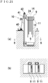
- the absorption apparatus 100 shown in Fig. 22 (a) is described.
- the absorption apparatus 100 is structured to supply a loop 101a, a loop 101b, a loop 101c, and a loop 101d of strips from the loop pit 102 side to the guide roller 104 provided on the holding arm 103.
- the strips flow from the guide roller 104 to the rolls 105 and the subsequent winding machine 112 side.
- the absorption apparatus 100 is structured so that the guide roller 104 is extended to the slitter 106 side via a cylinder device.
- the absorption apparatus 107 shown in Fig. 22(b) is also described.
- the absorption apparatus 107 is structured so that a carriage 109 to which the guide roller 108 is attached moves on a rail 110 extended in the horizontal direction. Strips flow to the rolls 111 and the subsequent winding machine side via the guide roller 108.
- Patent Document 2 a structure in which an absorption tower having a roll movable up and down is installed by the side of the loop pit, and when a loop sags, the loop is lifted up by the roll of the absorption tower.
- a pinch-roll type conveyance roll 114 that pinches strips by two rolls 113 disposed on the upper and lower sides and pushes the strips out to the winding machine side is installed in the looping region so that two-divided loops 116 are formed in the loop pit 115.
- Patent Document 1 and Patent Document 2 cannot sufficiently absorb the lengths of the loops.
- sufficient absorption of the loop amount means an increase in distance designated by the reference symbol H which is the difference between the lowermost loop 101d, that is, the largest loop, and the uppermost loop 101a.
- the strip in the middle of the loop is pinched by the pinch roll 113 and pushed out, so that two loops 116 can be formed in the loop pit.
- the necessity of pinching the strip becomes an issue.
- the second loop is formed, so that the strip is fed to the downstream side of the line while being gripped by a pressure, so that this pressure damages the surface of the strip.
- the damage on the strip surface becomes a fatal defect for a metal strip to be used for the purpose requiring high-quality surface finishing.
- the strip is formed of a thin material such as metal foil, the shape itself may be deformed.
- the present invention was made in view of the above-described circumstances, and an object thereof is to provide a loop amount absorption apparatus of a slitter line capable of absorbing sufficiently long loops generated on the line while hardly damaging metal strips.
- a loop amount absorption apparatus of a slitter line includes a rotating body that is constituted to be rotatable and movable up and down, and disposed between a slitter and a tensioner of the slitter line, a conduction hole which is provided inside the rotating body and in which a negative pressure is formed by a predetermined suction device, a conduction groove formed on the surface of the rotating body and connected to the conduction hole, and an outer layer portion low in breathability provided on the outside of the conduction groove.
- the conduction hole which is provided inside the rotating body and in which a negative pressure is formed by a predetermined suction device
- the pressure inside the rotating body can be made negative.
- a predetermined suction device for example, a vacuum pump or an ejector, etc., can be used, and by connecting this to the conduction hole, the air inside the rotating body is discharged and a negative pressure can be generated in the loop amount absorption apparatus.
- the conduction groove is formed on the surface of the rotating body and connected to the conduction hole, so that the conduction groove and the conduction hole conduct to each other, and the region of the negative pressure generated in the conduction hole can be broadened to the surface of the rotating body.
- the region of the negative pressure canbebroadened. That is, inside the apparatus, the negative pressure can be applied up to the end portion of the apparatus distant from the conduction hole.
- the negative pressure is applied to the strips in contact with the surface of the rotating body, and the strips can be adsorbed. Without damaging the surfaces of the strips, the strips can be gripped by the rotating body.
- the adsorption by a negative pressure mentioned here is caused by a pressing force applied by the atmosphere to the surfaces of the strips in contact with the rotating body.
- the conduction hole in which a negative pressure is formed by a predetermined suction device By the conduction hole in which a negative pressure is formed by a predetermined suction device, the conduction groove formed on the surface of the rotating body and connected to the conduction hole, and the outer layer portion low in breathability provided on the outside of the conduction groove, the amount of air to flow to the inside of the apparatus from the outside can be reduced while the region of the negative pressure inside the apparatus is broadened. That is, the degree of negative pressure inside the apparatus is increased, and the adsorption force to be applied to the strips in contact with the apparatus can be increased.
- the gripped strips can be conveyed to the downstream side of the slitter line while being gripped. That is, by disposing the rotating body at a position at which the strips loop, the rotating body can grip the strips and cause the strips to form two loops before and after the rotating body on the line. As a result, a larger difference between a large loop and a small loop can be allowed.
- the rotating body that is constituted to be rotatable and disposed between the slitter and the tensioner of the slitter line, two loops can be formed in the region between the slitter and the tensioner. That is, two loops are formed in the region in which a loop pit is usually provided.
- the rotating body constituted to be movable up and down, the height of the rotating body can be changed with respect to the strips to be threaded in the slitter line. That is, by lifting up the gripped strips to a height equal to or higher than the height of the strips being threaded, the loop amounts can be increased.
- the air permeability of the outer layer portion is 0.8 cm 3 /cm 2 ⁇ s or less measured by a Frazier type air permeability tester, the outer layer portion hardly sucks in extra outside air. As a result, the degree of negative pressure inside the apparatus becomes sufficiently high, and a sufficient gripping force can be applied to the strips.
- the rotating body When the rotating body is constituted to be movable up from the vicinity of a loop pit that is a recess formed in the region between the slitter and the tensioner, the installation space and installation labor of the apparatus can be reduced. In addition, efficiency of maintenance of the apparatus can be improved. That is, a structural body that enables the rotating body to move up is provided outside the loop pit, and the apparatus can be easily provided in the slitter line.
- the vicinity of the loop pit mentioned here means the region outside the loop pit, for example, a position which is flush with the floor surface on which the slitter and the tensioner are disposed, and on which the strips can be hung to form loops of the strips in the loop pit.
- the rotating body When the rotating body is constituted to be movable up from the vicinity of the bottom portion of the loop pit that is a recess formed in the region between the slitter and the tensioner, the operation of hanging the strips on the rotating body can be easily performed. For example, when a mechanism that automatically performs the operation of hanging the strips on the rotating body is adopted, the rotating body can be moved up from the position below the loops of the strips, so that the strips can be smoothly hung.
- the apparatus When the apparatus includes a sensor unit that is disposed near the bottom portion of the loop pit and can detect strips, a large loop can be detected before it comes into contact with the bottom of the loop pit.
- the gripping conveyance speed of strips by the apparatus can be synchronized with the threading speed of the strips in the slitter line. That is, according to the threading speed of strips, loops can be formed.
- the negative pressure generated in the conduction groove can be applied to the outer layer portion through the plurality of ventilation holes. Accordingly, a negative pressure can be efficiently generated in the outer layer portion.
- a negative pressure can be continuously applied to the strips in contact with the apparatus being rotated. That is, an adsorption force is continuously generated on the surface of the rotating body due to the negative pressure.
- a plurality of conduction holes are formed in the circumferential direction of the rotating body, the conduction holes adjacent to each other are at a fixed interval, a plurality of conduction grooves are formed in the longitudinal direction of the rotating body, and the conduction grooves adjacent to each other are at a fixed interval, unevenness of the adsorption force on the surface of the apparatus can be suppressed. That is, conduction holes and conduction grooves adjacent to each other do not communicate with each other, so that a state where only air at the position near the suction device is suctioned can be prevented, and a negative pressure can be uniformly generated up to the end portions of the rotating body.
- the degree of breathability of the outer layer portion can be easily adjusted. That is, for example, when it is desired to increase the degree of negative pressure inside the apparatus in such a case where strips are comparatively thick and need a strong gripping force, this can be realized by using non-woven fabric with extremely low breathability or forming a multi-layered structure by laminating a plurality of non-woven fabrics.
- the outer layer portion can be easily replaced, and maintenance of the apparatus is easily performed.
- the outer layer portion consists of a non-woven fabric low in breathability provided on the outside of the conduction groove and an outer layer member that is laminated on the outside of the non-woven fabric, has a frictional coefficient higher than that of the non-woven fabric, and has many minute through-holes formed therein, while the negative pressure inside the apparatus is increased, the frictional force between the outer layer portion and strips increases, so that the gripping force for gripping the strips can be increased.
- the loop amount absorption apparatus of a slitter line according to the present invention hardly damages the metal strips, and can absorb sufficiently long loops formed on the line.
- Fig. 1 is a schematic view showing an example and a disposing position of a loop amount absorption apparatus of a slitter line to which the present invention is applied.
- Fig. 2 is a schematic view showing a structure of a negative pressure roll.
- the absorption apparatus 1 as an example of the loop amount absorption apparatus of a slitter line to which the present invention is applied is disposed inside the region of the loop pit 3 provided in the slitter line 2.
- an uncoiler 4 that uncoils a metal strip from a rolled metal strip coil, and a slitter 5 that slits the metal strip into strips 14, are disposed.
- a tensioner 6 that applies a winding tensile force to the strips 14, a deflector roll 7 that changes the threading angle of the strips 14, and a winding machine 8 that winds the strips 14, are disposed.
- the absorption apparatus 1 includes a negative pressure roll 9 that grips and conveys the strips 14, and an up-down moving device 10 that enables the negative pressure roll 9 to move up and down. By gripping and conveying the strips 14 by the negative pressure roll 9, two loops 15 of the strips are formed.
- the separator 11 is a structure for stabilizing the strips 14 before the multiple strips 14 are brought into contact with the negative pressure roll 9 while preventing the strips 14 from overlapping each other.
- a sensor 12 that can detect strips 14 and interlock with the up-down moving device 10 is provided.
- a negative pressure roll standby position 13 capable of accommodating the negative pressure roll 9 inside is formed.
- the slitter line 2 is stopped and then the strips 14 are set on the negative pressure roll 9 and the separator 11.
- the negative pressure roll standby position 13 does not necessarily have to be formed at the center portion of the loop pit 3.
- a structure that causes the negative pressure roll 9 to stand by at a position on the bottom portion of the loop pit 3 or a position near the floor surface on which the slitter 5, etc., are installed, can also be adopted.
- the negative pressure roll 9 includes a rotating shaft 16, an inner cylinder 17, an intermediate cylinder 18, and a non-woven fabric laminated outer layer 19.
- the internal structure of the negative pressure roll 9 is described in detail.
- the rotating shaft 16 is a member that becomes the center of rotation of the negative pressure roll 9, and is connected to the inner cylinder 17 by a reinforcement disk 20.
- the inner cylinder 17 has a cylindrical shape, and rotates together with the rotating shaft 16.
- the rotating shaft 16 and the inner cylinder 17 are equivalent to the rotating body.
- the intermediate cylinder 18 is a cylindrical tubular material formed on the outside of the inner cylinder 17, and rotates in conjunction with the rotating shaft 16 and the inner cylinder 17.
- the non-woven fabric laminated outer layer 19 is formed on the outside of the intermediate cylinder 18, and is a portion at which the negative pressure roll 9 and the strips 14 come into contact with each other.
- the non-woven fabric laminated outer layer 19 also rotates in conjunction with the rotating shaft 16, the inner cylinder 17, and the intermediate cylinder 18.
- the negative pressure roll 9 has a drive motor 21.
- the drive motor 21 is connected to the rotating shaft 16 via a chain 22, and rotates the rotating shaft 16.
- the negative pressure roll 9 is joined to an up-down guide member 24 via the rotating shaft 16 and a bearing 23 supporting the rotating shaft 16.
- the up-down guide member 24 constitutes the up-down moving device 10 that enables the negative pressure roll 9 to move up and down in the vertical direction shown by the arrow Y.
- the negative pressure roll 9 does not necessarily have to consist of the rotating shaft 16, the inner cylinder 17, the intermediate cylinder 18, and the non-woven fabric laminated outer layer 19.
- manufacturing and maintenance of the negative pressure roll 6 become easy if it is divided into the respective members, and therefore, the negative pressure roll 9 preferably consists of the rotating shaft 16, the inner cylinder 17, the intermediate cylinder 18, and the non-woven fabric laminated outer layer 19.
- the rotating body does not necessarily have to consist of the rotating shaft 16, the inner cylinder 17, and the reinforcement disk 20.
- the rotatingbody preferably consists of the rotating shaft 16, the inner cylinder 17, and the reinforcement disk 20 since they provides strength to the rotating body.
- the strength can be further increased, and this is more preferable.
- the inner cylinder 17 may not be cylindrical, and it is possible that the negative pressure roll 9 includes the inner cylinder that is obtained by machining a solid material to become integral with the rotating shaft 17.
- the materials of the rotating shaft 16 and the inner cylinder 17 are not particularly restricted. For example, by using a plastic material, the manufacturing cost can be reduced.
- the structure among the rotating shaft 16, the inner cylinder 17, the intermediate cylinder 18, and the non-woven fabric laminated outer layer 19 is not restricted, and is only required to enable these members to rotate integrally in the same direction. Thatis, these members may be joined by fixtures, or a structure that rotates them integrally by frictional engagement caused by frictional forces applied between the members may be adopted.
- the kind of the bearing 23 is not particularly restricted.
- the bearing 23 may be a ball bearing.
- an anti-friction bearing or a sliding bearing is preferably adopted.
- the negative pressure roll 9 does not necessarily have to have the drive motor 21, and is only required to become rotatable by obtaining motive power.
- the structure and kind of the drive motor 21 are not particularly restricted.
- the drive motor 21 does not necessarily have to be connected to the rotating shaft 16 via the chain 22, and is only required to have a structure in which motive power generated by the drive motor 21 is transmitted to the rotating shaft 16.
- a structure in which the drive motor is connected by a V-belt instead of the chain and a structure in which the drive motor and the rotating shaft are directly connected, etc. can also be adopted.
- negative pressure conduction holes 25 pierced through the inner cylinder 17 are formed.
- the negative pressure conduction hole 25 serves as a flow passage of air when the air inside the negative pressure roll 9 is discharged by a vacuum pump (not illustrated).
- a plurality of negative pressure conduction holes are formed at fixed intervals in the circumferential direction of the inner cylinder 17.
- the arrow Z shows a direction of suctioning the negative pressure roll 9 by the vacuum pump.
- the suctioning amount of the outside air is limited by using the material low in breathability, so that it is not necessary to use an exhaust blower with a high capacity as a suction device.
- the back surfaces of the strips 14 in contact with the negative pressure roll 9 are maintained in a negative pressure state, and by pressing caused by the atmosphere, an adsorption force is generated, so that a vacuum pump or ejector, etc., that generates a high degree of vacuum although its suctioning amount is small can be used.
- negative pressure conduction grooves 26 connected to the negative pressure conduction holes 25 are provided on the surface of the inner cylinder 17.
- the negative pressure conduction grooves 26 are formed along the longitudinal direction of the negative pressure roll 9 to generate a negative pressure up to the end portions of the negative pressure roll 9.
- a negative pressure conduction portion 27 communicating with the negative pressure conduction holes 25 is provided on the rotating shaft 16 side of the negative pressure roll 9.
- the negative pressure conduction portion 27 is connected to the vacuum pump, and serves as a suction port for making the pressure inside the negative pressure roll 9 negative.
- the negative pressure conduction portion 27 is connected and fixed to the bearing 23, and increases the airtightness inside the negative pressure roll 9 while being in contact with the negative pressure conduction holes 25 rotating together with the rotating shaft 16.
- the negative pressure conduction holes 25 are only required to form a negative pressure inside the negative pressure roll 9, and the number of the negative pressure conduction holes and positions at which they are formed are not particularly restricted. However, for continuously providing a negative pressure to the negative pressure roll 9 being rotated, the negative pressure conduction holes 25 are preferably arranged at even intervals in the circumferential direction of the inner cylinder 17.
- the negative pressure conduction holes 25 do not necessarily have to be formed on only one end side of the inner cylinder 17.
- the negative pressure conduction holes 25 and a flow passage of the vacuum pump are provided on both sides of the inner cylinder 17 so that the air inside the negative pressure roll 9 is discharged from both end portions.
- the negative pressure conduction portion 27 does not necessarily have to be provided, and it is only required that a structure that can form a negative pressure inside the negative pressure roll 9 is provided, and other known technologies may be used. However, for increasing the airtightness inside the negative pressure roll 9, it is preferable to provide the negative pressure conduction portion 27.
- the negative pressure conduction portion 27 does not necessarily have to be connected to the bearing 23. However, it is preferable to connect the negative pressure conduction portion 27 and the bearing 23 since the negative pressure conduction portion 27 is accordingly fixed and the airtightness between the negative pressure conduction portion and the negative pressure conduction holes 25 is easily increased.
- Fig. 3 (a) is a cross sectional view taken along the line A-A and Fig. 3(b) is a cross sectional view taken along the line B-B in the schematic view shown in Fig. 2 .
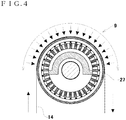
- Fig. 4 is a schematic cross sectional view of a negative pressure roll having a negative pressure region of 180 degrees on the roll circumference.
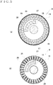
- Fig. 5(a) is a schematic cross sectional view at a position corresponding to a negative pressure conduction portion of another example of the negative pressure roll
- Fig. 5(b) is a schematic cross sectional view at a position corresponding to a negative pressure conduction portion of still another example of the negative pressure roll.
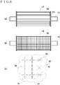
- Fig. 6(a) is a schematic view showing an inner cylinder
- Fig. 6(a) is a schematic view showing an inner cylinder
- FIG. 6(b) is a schematic view showing an intermediate cylinder
- Fig. 6 (c) is a schematic view showing ventilation hole groove portions provided around ventilation holes.
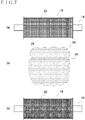
- Fig. 7(a) is a schematic view showing an intermediate cylinder using perforated metal
- Fig. 7 (b) is a schematic view showing many small-diameter holes of perforated metal
- Fig. 7 (c) is a schematic view showing a multi-layered non-woven fabric laminated outer cylinder.
- Fig. 8 (a) is a cross sectional view showing details of the X portion in Fig. 2
- Fig. 8(b) is a cross sectional view taken along the line C-C in the cross sectional view of Fig. 8(a).
- Fig. 9 (a) is a cross sectional view corresponding to Fig. 8 (a)
- Fig. 9 (b) is a cross sectional view corresponding to Fig. 8 (b) , showing another example of the negative pressure roll.
- On end side of the negative pressure roll 9 has the section as shown in Fig. 3(a) .
- the negative pressure conduction portion 27 and the negative pressure conduction holes 25 are provided on one end side of the negative pressure roll 9.
- the negative pressure conduction portion 27 is formed in a region accounting for approximately 90 degrees on the circumference of the negative pressure roll 9.
- the negative pressure roll 9 comes into contact with strips 14 at a position corresponding to this negative pressure conduction portion 27.
- the right-side drawing in Fig. 3(a) shows the surface region of the negative pressure roll 9 in an enlarged manner.
- the negative pressure roll 9 in the region distant from the one end side of the negative pressure roll 9, the negative pressure roll 9 consists of the inner cylinder 17, the negative pressure conduction grooves 26, the intermediate cylinder 18, and the non-woven fabric laminated outer layer 19.
- the negative pressure conduction portion 27 does not necessarily have to be formed in the region occupying approximately 90 degrees on the circumference of the negative pressure roll 9, and is only required to become capable of gripping and conveying strips 14.
- the negative pressure conduction portion 27 may be formed in the region of approximately 180 degrees on the circumference of the negative pressure roll 9.
- the negative pressure roll comes into contact with strips 14 that moved up from the lower side in the region of substantially 180 degrees on the negative pressure roll 9, so that a larger negative pressure can be applied to the strips. That is, a stronger gripping force can be applied.
- the negative pressure conduction portion 27 By preparing the negative pressure conduction portion 27 as a replacement part having an arbitrary angle, the negative pressure region in the circumferential direction can be arbitrarily adjusted.
- Fig. 5 (a) is a view showing a structure of another example of the negative pressure roll.
- the difference from the apparatus shown in Fig. 2 and Fig. 3 is in that partition projections 28 are provided on the surface of the inner cylinder 17 and the negative pressure conduction grooves 26 are formed between the partition projections 28.
- the negative pressure conduction grooves 26 may be formed as a layer separate from the inner cylinder 17.
- the partition projections come into close contact with the inner cylinder 17 and the intermediate cylinder 18, so that it is also possible to improve the airtightness of the negative pressure conduction grooves 26.
- Fig. 5(b) is a view showing a structure of still another example of the negative pressure roll.
- the apparatus shown in Fig. 5(b) has a structure without the intermediate cylinder 18.
- the apparatus shown in Fig. 5(b) has a rotating body 29.
- Such a simplified structure can also be adopted as long as it can apply a negative pressure to strips.
- the inner cylinder 17 is provided with pluralities of negative pressure conduction holes 25 and negative pressure conduction grooves 26.
- the right side in Fig. 6 (a) is the one end side of the negative pressure roll 9, and when the vacuum pump is operated, via the negative pressure conduction portion 27, a negative pressure is also generated in the negative pressure conduction holes 25 and the negative pressure conduction grooves 26.
- the negative pressure is applied by the negative pressure conduction grooves 26 up to the end portion on the side opposite to the side on which the negative pressure conduction holes 25 are provided.
- the intermediate cylinder 18 is provided on the outside of the inner cylinder 17.
- the intermediate cylinder 18 is formed of a tubular material made of metal, synthetic resin, or hard rubber, and in the surface thereof, many ventilation holes 30 are formed.
- the ventilation holes 30 are positioned at fixed intervals along the longitudinal direction and the circumferential direction of the intermediate cylinder 18 so that air flows from the ventilation holes 30 into the negative pressure conduction grooves 26 to generate a negative pressure.
- a ventilation hole groove portion 31 is formed toward four directions.
- the range of the air to be suctioned into the ventilation hole 30 is enlarged.
- the intermediate cylinder 18 and the ventilation holes 30 do not necessarily have to be formed, and it is only required that a negative pressure can be applied to the strips. However, a negative pressure can be efficiently generated on the non-woven fabric laminated outer layer 19 by forming the intermediate cylinder 18 and providing the ventilation holes 30, so that it is preferable to form the intermediate cylinder 18 and the ventilation holes 30.
- the ventilation hole groove portion 31 does not necessarily have to be provided around the ventilation hole 30. However, by enlarging the negative pressure generation region, the degree of negative pressure inside the negative pressure roll 9 can be further increased, so that it is preferable to provide the ventilation hole groove portion 31 around the ventilation hole 30.
- the shape of the ventilation hole groove portion is not particularly restricted, and the ventilation hole groove portion 32 may be formed toward eight directions by increasing the number of grooves as shown in Fig. 6(c) .
- Fig. 7(a) shows an intermediate cylinder 18 made of perforated metal 33 as another example of the intermediate cylinder 18.
- the perforated metal 33 is a material in which many small-diameter holes 34 are formed by punching a planar metal strip.
- Fig. 7(b) shows small-diameter holes 34 formed in the perforated metal 33.
- the small-diameter holes 34 flow air into the negative pressure conduction grooves 26, however, the small-diameter holes are smaller than the ventilation holes 30.
- the perforated metal 33 one available on the market can also be used.
- the non-woven fabric laminated outer layer 19 is provided on the outside of the intermediate cylinder 18.
- the non-woven fabric laminated outer layer 19 is made of non-woven fabric 35 low in breathability, and its air permeability is 0.8 cm 3 /cm 2 ⁇ s or less measured by a Frazier type air permeability tester.
- the non-woven fabric 35 has an appropriate frictional coefficient and elasticity, and generates a sufficient frictional force between this and strips 14, and hardly damages the strips even when it comes into contact with the strips.
- the non-woven fabric laminated outer layer 19 does not necessarily have to be made of non-woven fabric 35 low in breathability, and it is only required to apply a negative pressure to strips. However, it is preferable to make the non-woven fabric laminated outer layer 19 of the non-woven fabric 35 low in breathability since this makes it possible to easily adjust the air permeability of the outer layer portion.
- the air permeability of the non-woven fabric laminated outer layer 19 does not necessarily have to be 0.8 cm 3 /cm 2 ⁇ s or less measured by a Frazier type air permeability tester, and it is only required to apply a negative pressure to strips. However, it is preferable to set the air permeability of the non-woven fabric laminated outer layer 19 to 0.8 cm 3 /cm 2 ⁇ s or less measured by a Frazier type air permeability tester since this increases the degree of negative pressure inside the negative pressure roll and makes it possible to sufficiently grip and convey the strips 14.
- Fig. 8(a) shows details of the X portion of the negative pressure roll shown in Fig. 2 .
- the negative pressure conduction grooves 26 are formed on the surface of the inner cylinder 17, and ventilation holes 30 of the intermediate cylinder 18 are positioned at fixed intervals. Further, on the outside of the ventilation holes 30, the non-woven fabric laminated outer layer 19 is formed, and strips 14 come into contact with the non-woven fabric.
- Fig. 8(b) is a cross sectional view in the C-C direction of the cross sectional view of Fig. 8(a) .
- the view of Fig. 8(b) is in an arc shape in actuality, however, for convenience of description, it is shown as a linear view.
- Fig. 9(a) shows details of the X portion of the negative pressure roll in the case where the intermediate cylinder 18 is formed of perforated metal 33.
- the negative pressure conduction grooves 26 are formed, and on the outside thereof, the perforated metal 33 is positioned.
- the non-woven fabric laminated outer layer 19 is formed, and strips 14 come into contact with the non-woven fabric.
- Fig. 9 (b) is a cross sectional view in the C-C direction of the cross sectional view of Fig. 9(a) .
- the view of Fig. 9(b) is in an arc shape in actuality, however, for convenience of description, it is shown as a linear view.
- the non-woven fabric used in the negative pressure roll is described.
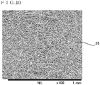
- Fig. 10 is a view showing an enlarged microphotograph of the non-woven fabric used in the negative pressure roll.
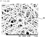
- Fig. 11 is a view showing an enlarged microphotograph of generally used non-woven fabric.
- Fig. 12 is a view showing an enlarged microphotograph of high-density woven fabric.
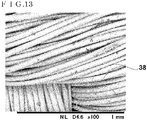
- Fig. 13 is a view showing an enlarged microphotograph of generally used woven fabric.
- Fig. 10 shows a microphotograph (the magnification of 100 times) of the non-woven fabric 35 used in the negative pressure roll 9.
- the non-woven fabric 35 is formed by entwining fibers with a fiber diameter of approximately 4 ⁇ m at a high density.
- One non-woven fabric 35 is used, and it can realize low air permeability of approximately 0.8 cm 3 /cm 2 ⁇ s or less measured by a Frazier type air permeability tester. Between the extra fine fibers of the non-woven fabric 35, many spaces with sizes of micrometers are present, and through these spaces, the negative pressure easily reach the entire surface of the non-woven fabric laminated outer layer 19.
- Fig. 11 shows a microphotograph of the non-woven fabric 36 generally used for a tension pad that is one of tensioners.
- the non-woven fabric 36 is formed by entwining fibers with a fiber diameter of approximately 20 to 30 ⁇ m, and is lower in density than the non-woven fabric 35.
- One non-woven fabric 36 is used, and its Frazier type air permeability is 50 to 100 cm 3 /cm 2 ⁇ s, and it is difficult to use this as non-woven fabric of the non-woven fabric laminated outer layer 19.
- non-woven fabric 36 by combining the non-woven fabric 36 with a material low in air permeability of approximately 0.8 cm 3 /cm 2 ⁇ s or less measured by a Frazier type air permeability tester, for example, high-density woven fabric 37 such as nylon woven fabric, low breathability can also be realized. That is, it is also possible that by sandwiching a high-density woven fabric 37 between non-woven fabrics 36, the non-woven fabric laminated outer layer 19 can be formed.
- Fig. 12 shows the high-density woven fabric 37 and
- Fig. 13 shows the generally used woven fabric 38 as enlarged microphotographs (the magnification of 100 times).
- the non-woven fabric laminated outer layer 19 does not necessarily have to be formed of one non-woven fabric 35.
- a structure that realizes low air permeability by overlapping a plurality of non-woven fabrics can also be adopted.
- a structure in which a non-woven fabric low in breathability and artificial leather which is laminated on the outside of the non-woven fabric and with many minute through-holes are combined to form the outer layer portion can also be adopted.
- artificial leather by using a material with a frictional coefficient higher than that of the non-woven fabric, the gripping force for gripping strips can be increased.
- amaterialwithafrictional coefficient higher than that of the non-woven fabric can be used, and for example, a rubber material can also be used.
- Fig. 14 is a schematic view of the negative pressure roll and the up-down moving device from the side.
- the negative pressure roll 9 can be moved up and down in the vertical direction by the up-down moving device 10.
- the up-down moving device 10 includes an up-down guide member 24 joined to the above-described negative pressure roll 9, a guide post 39 which is provided in the loop pit 3 and to which the guide member 24 is attached, and a motor-driven winch 40.
- a rope 41 is anchored, and via a guide roll 42 disposed on the tip end of the guide post 39, the rope 41 is wound by the motor-driven winch 40.
- the arrow Y in the drawing shows the up-down moving direction of the negative pressure roll 9, and the negative pressure roll 9 is movable up and down in the range from the bottom surface of the loop pit 3 to the upper end of the guide post 39.
- the guide post 39 and the guide member 24 are joined by a known linear guide rail structure, and can move the negative pressure roll 9 up and down while keeping it in a horizontal direction.
- the constitution of the up-down moving device 10 does not necessarily have to be adopted to move the negative pressure roll 9 up and down, and it is only required to stably move the negative pressure roll 9 up and down in the vertical direction.
- a drive source an electrically-operated treaded rod rotating structure and a telescoping structure using a hydraulic cylinder, etc., can also be adopted as well as the motor-driven winch.
- Fig. 15(a) is a schematic view when starting operation of the slitter line and Fig. 15(b) is a schematic view when the loop hang-down amounts of strips change.
- Fig. 16(a) is a schematic view showing a state where strips are set on the negative pressure roll
- Fig. 16(b) is a schematic view showing a state where the negative pressure roll moves up.
- Fig. 17(a) is a schematic view showing a state where the negative pressure roll is at a moved-up position and the loop hang-down amounts increase
- Fig. 17(b) is a schematic view showing a state where the negative pressure roll moves up to the upper limit of the up-down guide post.
- the speeds of the uncoiler 4, the slitter 5, and the winding machine 8 are synchronized and threading of the strips 14 is started.
- the negative pressure roll 9 is stored at the negative pressure roll standby position 13 on the bottom surface of the loop pit 3.
- the negative pressure roll 9 does not necessarily have to be positioned at the negative pressure roll standby position 13.
- the up-down moving device 10 is operated to move up the negative pressure roll 9 to the vicinity of the floor surface 47.
- the slitter line 2 is temporarily stopped and the strips 14 are set on the negative pressure roll 9 and the separator 11.
- the operation of setting the strips 14 can be easily performed. Detection before the loop 45 of the strip 14 whose wound coil diameter is small comes into contact with the floor surface of the loop pit 3 can be performed with the sensor 12. This operation can also be performed by visual confirmation.
- the rotation speed of the negative pressure roll 9 is electrically programmed so as to synchronize with the line speed.
- the negative pressure roll 9 can be moved up by the up-down moving device 10 while being operated. According to moving up of the negative pressure roll 9, it becomes possible to increase the hang-down amounts of the two loops. That is, it becomes possible to allow a larger difference between a large loop and a small loop of the strips.
- the hang-down amounts of the two loops can be further increased. That is, it becomes possible to allow a still larger difference between a large loop and a small loop of the strips. It is also possible that, in this case, the negative pressure roll 9 is automatically moved up in response to a signal from the sensor 12.
- two loops of the strips 14 can be formed before and after the negative pressure roll 9, so that as compared with a conventional slitter line having only the loop pit, the loop amounts can be sufficiently absorbed.
- the loop amounts that can be absorbed can be increased.
- the up-down moving device when the up-down moving device is installed in an existing loop pit, the loop amount absorption efficiency can be improved.
- a new loop pit When a new loop pit is provided, it becomes unnecessary to form the loop pit deep, and this leads to a reduction in cost of the facility in which the slitter line is installed and improvement in safety.
- the negative pressure roll 9 grips strips 14 by a negative pressure, so that the surfaces of the strips 14 are hardly damaged.
- the non-woven fabric laminated outer layer 19 of the negative pressure roll 9 is made of non-woven fabric low in air permeability, so that the surfaces of the strips 14 are even less likely to be damaged.
- a structure in which the up-down moving device is provided near the loop pit can also be adopted.
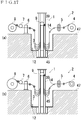
- Fig. 18(a) is a schematic view of the apparatus in which an up-down moving device is provided near a loop pit
- Fig. 18 (b) is a side view in the direction A-A in Fig. 18(a)
- Fig. 19 (a) is a schematic view showing a state where strips are set on the apparatus in which an up-down moving device is provided near a loop pit
- Fig. 19 (b) is a side view in the direction B-B in Fig. 19(a) .
- the up-down moving device 10 is provided not inside the loop pit 3 but on the floor surface 47 on which the slitter 5 and the tensioner 6 are disposed.
- the negative pressure roll 9 is movable up and down near the loop pit 3.
- the negative pressure roll 9 stands by at the upper portion of the up-down moving device 10. Thereafter, when the loop of the strip whose wound coil diameter is small comes to a position at which the wound coil diameter almost comes into contact with the floor surface of the loop pit 3, the line is stopped, and the negative pressure roll 9 is moved down to the position of the floor surface 47.
- Fig. 18(b) shows this state from the direction of the arrow A-A in Fig. 18(a) .
- FIG. 19(a) A view of the state where the strips 14 are set on the negative pressure roll 9 when the line is stopped from the direction of the arrow B-B in Fig. 19(a) is as shown in Fig. 19(a) .
- the negative pressure roll 9 and the line are operated, and while the strips 14 are gripped and conveyed, the negative pressure roll 9 is moved up by the up-down moving device 10, and accordingly, it becomes possible to increase the hang-down amounts of the two loops. That is, it becomes possible to allow a still larger difference between a large loop and a small loop of the strips.
- the space and labor for installing the up-down moving device 10, specifically, the up-down post guide 39 can be reduced.
- a structure in which two absorption apparatuses are provided on the slitter line can also be adopted.
- Fig. 20 is a schematic view of the slitter line in the case where two absorption apparatuses are provided.
- Fig. 21(a) is a side view in the arrow A-A direction in Fig. 20
- Fig. 21 (b) is a plan view in the arrow B direction in Fig. 21(a) .
- the embodiment of the present invention is not limited to the structure in which two absorption apparatuses 1 are provided, and a structure in which three or more absorption apparatuses are provided and a structure in which two absorption apparatuses are provided at a distance are also possible as necessary.
- the loop amount absorption apparatus of a slitter line according to the present invention hardly damages the metal strips, and can absorb sufficiently long loops formed on the line.
Landscapes
- Engineering & Computer Science (AREA)
- Mechanical Engineering (AREA)
- Life Sciences & Earth Sciences (AREA)
- Forests & Forestry (AREA)
- Registering, Tensioning, Guiding Webs, And Rollers Therefor (AREA)
- Winding, Rewinding, Material Storage Devices (AREA)
- Winding Of Webs (AREA)
- Advancing Webs (AREA)
- Shearing Machines (AREA)
- Accessories And Tools For Shearing Machines (AREA)
- Treatment Of Fiber Materials (AREA)
Applications Claiming Priority (1)
| Application Number | Priority Date | Filing Date | Title |
|---|---|---|---|
| PCT/JP2014/052466 WO2015114837A1 (ja) | 2014-02-03 | 2014-02-03 | スリッターラインのループ量吸収装置 |
Publications (3)
| Publication Number | Publication Date |
|---|---|
| EP3103556A1 true EP3103556A1 (de) | 2016-12-14 |
| EP3103556A4 EP3103556A4 (de) | 2017-11-29 |
| EP3103556B1 EP3103556B1 (de) | 2021-01-27 |
Family
ID=52339830
Family Applications (1)
| Application Number | Title | Priority Date | Filing Date |
|---|---|---|---|
| EP14789969.4A Active EP3103556B1 (de) | 2014-02-03 | 2014-02-03 | Bandspeicher für längsschneidelinien |
Country Status (8)
| Country | Link |
|---|---|
| US (1) | US9890006B2 (de) |
| EP (1) | EP3103556B1 (de) |
| JP (1) | JP5652800B1 (de) |
| KR (1) | KR101629492B1 (de) |
| CN (1) | CN105377460B (de) |
| ES (1) | ES2857678T3 (de) |
| TW (1) | TWI569899B (de) |
| WO (1) | WO2015114837A1 (de) |
Cited By (1)
| Publication number | Priority date | Publication date | Assignee | Title |
|---|---|---|---|---|
| EP3115138A4 (de) * | 2014-03-07 | 2017-10-25 | JDC, Inc. | Unterdruckfolienstruktur |
Families Citing this family (6)
| Publication number | Priority date | Publication date | Assignee | Title |
|---|---|---|---|---|
| KR101879584B1 (ko) * | 2016-12-30 | 2018-07-18 | 주식회사 성우하이텍 | 루프 시스템용 코일감지장치 |
| CN108249199A (zh) * | 2017-03-01 | 2018-07-06 | 常州百利菲特防水设备有限公司 | 防水设备储毡机 |
| US10370214B2 (en) * | 2017-05-31 | 2019-08-06 | Cryovac, Llc | Position control system and method |
| KR101887823B1 (ko) * | 2017-08-30 | 2018-08-10 | 김태원 | 엘리베이터 루퍼가 설치된 슬리팅 라인 |
| KR101896191B1 (ko) * | 2017-08-30 | 2018-09-06 | 김태원 | 다이렉트 이송식 슬리팅 라인 |
| CN116652047B (zh) * | 2023-08-01 | 2023-10-27 | 南京天河汽车零部件股份有限公司 | 一种多工位智能冲压件制造生产装置及其生产上料方法 |
Family Cites Families (25)
| Publication number | Priority date | Publication date | Assignee | Title |
|---|---|---|---|---|
| US3835681A (en) * | 1973-03-16 | 1974-09-17 | Wean United Inc | Continuous rolling mill |
| JPH0543925Y2 (de) * | 1986-12-24 | 1993-11-08 | ||
| JPH074622B2 (ja) * | 1988-07-12 | 1995-01-25 | 三菱重工業株式会社 | 極薄帯板巻取り機の張力調整装置 |
| JPH0397442A (ja) | 1989-09-08 | 1991-04-23 | Olympus Optical Co Ltd | 蛍光観察用内視鏡装置 |
| JPH03106512A (ja) * | 1989-09-19 | 1991-05-07 | Kawasaki Steel Corp | スリッタラインにおけるルーピング装置及びその操業方法 |
| JP2508348Y2 (ja) | 1990-01-26 | 1996-08-21 | 日新製鋼株式会社 | スリッタ―ラインのル―プ吸収タワ― |
| US5617134A (en) * | 1994-03-25 | 1997-04-01 | Energy Saving Products And Sales Corporation | Machine for manipulating and working on web material |
| JPH0826543A (ja) * | 1994-07-12 | 1996-01-30 | Nippon Steel Corp | 導電性帯体の位置決め装置 |
| JP3517288B2 (ja) * | 1994-10-14 | 2004-04-12 | 大日本印刷株式会社 | 送りローラおよび給紙装置 |
| JP3324558B2 (ja) | 1999-04-26 | 2002-09-17 | 山王鉄工株式会社 | スリッターラインのループ伸び吸収装置 |
| JP4281031B2 (ja) * | 1999-06-02 | 2009-06-17 | 株式会社Ihi | 板厚圧下プレス用のループ形成設備及びループ形成方法 |
| CN2493597Y (zh) * | 2001-08-30 | 2002-05-29 | 古国麟 | 台式全自动纵横裁切机 |
| JP2003312909A (ja) * | 2002-04-22 | 2003-11-06 | Hikoyama Seiki Kk | 自己吸引式サクションロール及びこのサクションロールを用いたフィルム状基材の搬送装置 |
| JP3950040B2 (ja) * | 2002-08-30 | 2007-07-25 | 東芝機械株式会社 | サクションロール装置 |
| US20040155137A1 (en) * | 2003-02-06 | 2004-08-12 | Sharpe Brett E. | Capstan assembly and control system |
| TWI247073B (en) * | 2004-01-15 | 2006-01-11 | Ching Feng Blinds Ind Co Ltd | Process and device for forming cloth-shutter blades |
| US8640862B2 (en) * | 2006-04-10 | 2014-02-04 | Albany International Corp. | Seam-on laminated belt |
| JP4873345B2 (ja) * | 2006-12-05 | 2012-02-08 | 株式会社ハイメックス | サクションロール装置 |
| US7905443B2 (en) * | 2007-10-26 | 2011-03-15 | Papania James F | Adjustable vertical accumulator for slitting operation |
| JP4625516B2 (ja) * | 2008-10-06 | 2011-02-02 | 株式会社日本開発コンサルタント | ベルト式帯板巻取り張力付与装置のスリット入りエンドレスベルト |
| US8201429B1 (en) * | 2009-02-03 | 2012-06-19 | Braner Usa, Inc. | Blanking line using slitter as feeder |
| CN202367522U (zh) * | 2011-12-27 | 2012-08-08 | 东风汽车股份有限公司 | 柔性上料剪切装置 |
| US8931675B2 (en) * | 2012-02-08 | 2015-01-13 | Carpe Diem Technologies, Inc. | Web handling system and vacuum roller for use in conjunction therewith |
| JP5565889B1 (ja) * | 2013-02-06 | 2014-08-06 | Jdc株式会社 | サクションロール装置 |
| CN103121036B (zh) * | 2013-02-27 | 2015-05-20 | 云南铝业股份有限公司 | 一种冷轧铝卷的纵切紧模式分条方法 |
-
2014
- 2014-02-03 JP JP2014519121A patent/JP5652800B1/ja active Active
- 2014-02-03 EP EP14789969.4A patent/EP3103556B1/de active Active
- 2014-02-03 WO PCT/JP2014/052466 patent/WO2015114837A1/ja not_active Ceased
- 2014-02-03 CN CN201480001404.0A patent/CN105377460B/zh active Active
- 2014-02-03 KR KR1020147033568A patent/KR101629492B1/ko active Active
- 2014-02-03 ES ES14789969T patent/ES2857678T3/es active Active
- 2014-02-03 US US14/403,205 patent/US9890006B2/en active Active
- 2014-11-12 TW TW103139228A patent/TWI569899B/zh active
Cited By (1)
| Publication number | Priority date | Publication date | Assignee | Title |
|---|---|---|---|---|
| EP3115138A4 (de) * | 2014-03-07 | 2017-10-25 | JDC, Inc. | Unterdruckfolienstruktur |
Also Published As
| Publication number | Publication date |
|---|---|
| TWI569899B (zh) | 2017-02-11 |
| TW201534411A (zh) | 2015-09-16 |
| WO2015114837A1 (ja) | 2015-08-06 |
| CN105377460B (zh) | 2017-04-19 |
| KR20150103625A (ko) | 2015-09-11 |
| ES2857678T3 (es) | 2021-09-29 |
| US20160263766A1 (en) | 2016-09-15 |
| KR101629492B1 (ko) | 2016-06-10 |
| EP3103556B1 (de) | 2021-01-27 |
| EP3103556A4 (de) | 2017-11-29 |
| JP5652800B1 (ja) | 2015-01-14 |
| CN105377460A (zh) | 2016-03-02 |
| JPWO2015114837A1 (ja) | 2017-03-23 |
| US9890006B2 (en) | 2018-02-13 |
Similar Documents
| Publication | Publication Date | Title |
|---|---|---|
| EP3103556B1 (de) | Bandspeicher für längsschneidelinien | |
| EP2955136B1 (de) | Saugwalzenvorrichtung | |
| CN202186781U (zh) | 膜卷放卷装置 | |
| CN103771188B (zh) | 一种自动盘软管机 | |
| MXPA05003467A (es) | Aparato rebobinador y metodo. | |
| CN109132693A (zh) | 一种针织拉布机及其铺布方法 | |
| CN104444500A (zh) | 一种储料架结构 | |
| KR101894445B1 (ko) | 부압 시트 구조 | |
| CN201483551U (zh) | 一种切边机 | |
| CN203212112U (zh) | 自动盘软管机 | |
| CN115611042A (zh) | 一种全自动高速分切机 | |
| CN209259312U (zh) | 放卷夹紧组件和分切机 | |
| JP2019059567A (ja) | ゴムストリップ搬送装置 | |
| CN222156762U (zh) | 一种石墨带滚压装置 | |
| CN223265529U (zh) | 一种管道穿管装置 | |
| CN223342025U (zh) | 一种高速分切机 | |
| KR100733411B1 (ko) | 원지테이프 권취장치 | |
| CN120461528A (zh) | 一种具有精准输送结构的卷对卷冲孔设备 | |
| CN215149468U (zh) | 拉力带横向裁切设备 | |
| CN214733239U (zh) | 用于胶带割孔的拉带卷带计数装置 | |
| US11286129B2 (en) | Sheet supply device and sheet supply method | |
| CN103213877B (zh) | 换位回转装置 | |
| CN121591031A (zh) | 一种裁床设备的送料装置以及送料方法 | |
| CN119503521A (zh) | 一种自动分条机及其工作方法 | |
| JP2015168004A (ja) | スペーサ投入装置 |
Legal Events
| Date | Code | Title | Description |
|---|---|---|---|
| PUAI | Public reference made under article 153(3) epc to a published international application that has entered the european phase |
Free format text: ORIGINAL CODE: 0009012 |
|
| STAA | Information on the status of an ep patent application or granted ep patent |
Free format text: STATUS: REQUEST FOR EXAMINATION WAS MADE |
|
| 17P | Request for examination filed |
Effective date: 20141105 |
|
| AK | Designated contracting states |
Kind code of ref document: A1 Designated state(s): AL AT BE BG CH CY CZ DE DK EE ES FI FR GB GR HR HU IE IS IT LI LT LU LV MC MK MT NL NO PL PT RO RS SE SI SK SM TR |
|
| AX | Request for extension of the european patent |
Extension state: BA ME |
|
| DAX | Request for extension of the european patent (deleted) | ||
| A4 | Supplementary search report drawn up and despatched |
Effective date: 20171026 |
|
| RIC1 | Information provided on ipc code assigned before grant |
Ipc: B65H 23/18 20060101ALI20171020BHEP Ipc: B23D 33/00 20060101ALI20171020BHEP Ipc: B21C 49/00 20060101AFI20171020BHEP |
|
| STAA | Information on the status of an ep patent application or granted ep patent |
Free format text: STATUS: EXAMINATION IS IN PROGRESS |
|
| 17Q | First examination report despatched |
Effective date: 20190408 |
|
| GRAP | Despatch of communication of intention to grant a patent |
Free format text: ORIGINAL CODE: EPIDOSNIGR1 |
|
| STAA | Information on the status of an ep patent application or granted ep patent |
Free format text: STATUS: GRANT OF PATENT IS INTENDED |
|
| INTG | Intention to grant announced |
Effective date: 20200827 |
|
| GRAS | Grant fee paid |
Free format text: ORIGINAL CODE: EPIDOSNIGR3 |
|
| GRAA | (expected) grant |
Free format text: ORIGINAL CODE: 0009210 |
|
| STAA | Information on the status of an ep patent application or granted ep patent |
Free format text: STATUS: THE PATENT HAS BEEN GRANTED |
|
| AK | Designated contracting states |
Kind code of ref document: B1 Designated state(s): AL AT BE BG CH CY CZ DE DK EE ES FI FR GB GR HR HU IE IS IT LI LT LU LV MC MK MT NL NO PL PT RO RS SE SI SK SM TR |
|
| REG | Reference to a national code |
Ref country code: GB Ref legal event code: FG4D |
|
| REG | Reference to a national code |
Ref country code: CH Ref legal event code: EP |
|
| REG | Reference to a national code |
Ref country code: AT Ref legal event code: REF Ref document number: 1357867 Country of ref document: AT Kind code of ref document: T Effective date: 20210215 |
|
| REG | Reference to a national code |
Ref country code: IE Ref legal event code: FG4D |
|
| REG | Reference to a national code |
Ref country code: DE Ref legal event code: R096 Ref document number: 602014074585 Country of ref document: DE |
|
| REG | Reference to a national code |
Ref country code: CH Ref legal event code: NV Representative=s name: HEPP WENGER RYFFEL AG, CH |
|
| REG | Reference to a national code |
Ref country code: NL Ref legal event code: MP Effective date: 20210127 |
|
| REG | Reference to a national code |
Ref country code: LT Ref legal event code: MG9D |
|
| REG | Reference to a national code |
Ref country code: AT Ref legal event code: MK05 Ref document number: 1357867 Country of ref document: AT Kind code of ref document: T Effective date: 20210127 |
|
| PG25 | Lapsed in a contracting state [announced via postgrant information from national office to epo] |
Ref country code: NL Free format text: LAPSE BECAUSE OF FAILURE TO SUBMIT A TRANSLATION OF THE DESCRIPTION OR TO PAY THE FEE WITHIN THE PRESCRIBED TIME-LIMIT Effective date: 20210127 Ref country code: NO Free format text: LAPSE BECAUSE OF FAILURE TO SUBMIT A TRANSLATION OF THE DESCRIPTION OR TO PAY THE FEE WITHIN THE PRESCRIBED TIME-LIMIT Effective date: 20210427 Ref country code: BG Free format text: LAPSE BECAUSE OF FAILURE TO SUBMIT A TRANSLATION OF THE DESCRIPTION OR TO PAY THE FEE WITHIN THE PRESCRIBED TIME-LIMIT Effective date: 20210427 Ref country code: LT Free format text: LAPSE BECAUSE OF FAILURE TO SUBMIT A TRANSLATION OF THE DESCRIPTION OR TO PAY THE FEE WITHIN THE PRESCRIBED TIME-LIMIT Effective date: 20210127 Ref country code: PT Free format text: LAPSE BECAUSE OF FAILURE TO SUBMIT A TRANSLATION OF THE DESCRIPTION OR TO PAY THE FEE WITHIN THE PRESCRIBED TIME-LIMIT Effective date: 20210527 Ref country code: HR Free format text: LAPSE BECAUSE OF FAILURE TO SUBMIT A TRANSLATION OF THE DESCRIPTION OR TO PAY THE FEE WITHIN THE PRESCRIBED TIME-LIMIT Effective date: 20210127 Ref country code: GR Free format text: LAPSE BECAUSE OF FAILURE TO SUBMIT A TRANSLATION OF THE DESCRIPTION OR TO PAY THE FEE WITHIN THE PRESCRIBED TIME-LIMIT Effective date: 20210428 Ref country code: FI Free format text: LAPSE BECAUSE OF FAILURE TO SUBMIT A TRANSLATION OF THE DESCRIPTION OR TO PAY THE FEE WITHIN THE PRESCRIBED TIME-LIMIT Effective date: 20210127 |
|
| PG25 | Lapsed in a contracting state [announced via postgrant information from national office to epo] |
Ref country code: SE Free format text: LAPSE BECAUSE OF FAILURE TO SUBMIT A TRANSLATION OF THE DESCRIPTION OR TO PAY THE FEE WITHIN THE PRESCRIBED TIME-LIMIT Effective date: 20210127 Ref country code: RS Free format text: LAPSE BECAUSE OF FAILURE TO SUBMIT A TRANSLATION OF THE DESCRIPTION OR TO PAY THE FEE WITHIN THE PRESCRIBED TIME-LIMIT Effective date: 20210127 Ref country code: LV Free format text: LAPSE BECAUSE OF FAILURE TO SUBMIT A TRANSLATION OF THE DESCRIPTION OR TO PAY THE FEE WITHIN THE PRESCRIBED TIME-LIMIT Effective date: 20210127 Ref country code: PL Free format text: LAPSE BECAUSE OF FAILURE TO SUBMIT A TRANSLATION OF THE DESCRIPTION OR TO PAY THE FEE WITHIN THE PRESCRIBED TIME-LIMIT Effective date: 20210127 Ref country code: AT Free format text: LAPSE BECAUSE OF FAILURE TO SUBMIT A TRANSLATION OF THE DESCRIPTION OR TO PAY THE FEE WITHIN THE PRESCRIBED TIME-LIMIT Effective date: 20210127 |
|
| REG | Reference to a national code |
Ref country code: ES Ref legal event code: FG2A Ref document number: 2857678 Country of ref document: ES Kind code of ref document: T3 Effective date: 20210929 |
|
| PG25 | Lapsed in a contracting state [announced via postgrant information from national office to epo] |
Ref country code: IS Free format text: LAPSE BECAUSE OF FAILURE TO SUBMIT A TRANSLATION OF THE DESCRIPTION OR TO PAY THE FEE WITHIN THE PRESCRIBED TIME-LIMIT Effective date: 20210527 |
|
| REG | Reference to a national code |
Ref country code: BE Ref legal event code: MM Effective date: 20210228 |
|
| REG | Reference to a national code |
Ref country code: DE Ref legal event code: R097 Ref document number: 602014074585 Country of ref document: DE |
|
| PG25 | Lapsed in a contracting state [announced via postgrant information from national office to epo] |
Ref country code: EE Free format text: LAPSE BECAUSE OF FAILURE TO SUBMIT A TRANSLATION OF THE DESCRIPTION OR TO PAY THE FEE WITHIN THE PRESCRIBED TIME-LIMIT Effective date: 20210127 Ref country code: CZ Free format text: LAPSE BECAUSE OF FAILURE TO SUBMIT A TRANSLATION OF THE DESCRIPTION OR TO PAY THE FEE WITHIN THE PRESCRIBED TIME-LIMIT Effective date: 20210127 Ref country code: MC Free format text: LAPSE BECAUSE OF FAILURE TO SUBMIT A TRANSLATION OF THE DESCRIPTION OR TO PAY THE FEE WITHIN THE PRESCRIBED TIME-LIMIT Effective date: 20210127 Ref country code: LU Free format text: LAPSE BECAUSE OF NON-PAYMENT OF DUE FEES Effective date: 20210203 Ref country code: SM Free format text: LAPSE BECAUSE OF FAILURE TO SUBMIT A TRANSLATION OF THE DESCRIPTION OR TO PAY THE FEE WITHIN THE PRESCRIBED TIME-LIMIT Effective date: 20210127 |
|
| PG25 | Lapsed in a contracting state [announced via postgrant information from national office to epo] |
Ref country code: RO Free format text: LAPSE BECAUSE OF FAILURE TO SUBMIT A TRANSLATION OF THE DESCRIPTION OR TO PAY THE FEE WITHIN THE PRESCRIBED TIME-LIMIT Effective date: 20210127 Ref country code: SK Free format text: LAPSE BECAUSE OF FAILURE TO SUBMIT A TRANSLATION OF THE DESCRIPTION OR TO PAY THE FEE WITHIN THE PRESCRIBED TIME-LIMIT Effective date: 20210127 Ref country code: DK Free format text: LAPSE BECAUSE OF FAILURE TO SUBMIT A TRANSLATION OF THE DESCRIPTION OR TO PAY THE FEE WITHIN THE PRESCRIBED TIME-LIMIT Effective date: 20210127 |
|
| PLBE | No opposition filed within time limit |
Free format text: ORIGINAL CODE: 0009261 |
|
| STAA | Information on the status of an ep patent application or granted ep patent |
Free format text: STATUS: NO OPPOSITION FILED WITHIN TIME LIMIT |
|
| 26N | No opposition filed |
Effective date: 20211028 |
|
| PG25 | Lapsed in a contracting state [announced via postgrant information from national office to epo] |
Ref country code: IE Free format text: LAPSE BECAUSE OF NON-PAYMENT OF DUE FEES Effective date: 20210203 Ref country code: AL Free format text: LAPSE BECAUSE OF FAILURE TO SUBMIT A TRANSLATION OF THE DESCRIPTION OR TO PAY THE FEE WITHIN THE PRESCRIBED TIME-LIMIT Effective date: 20210127 |
|
| PG25 | Lapsed in a contracting state [announced via postgrant information from national office to epo] |
Ref country code: SI Free format text: LAPSE BECAUSE OF FAILURE TO SUBMIT A TRANSLATION OF THE DESCRIPTION OR TO PAY THE FEE WITHIN THE PRESCRIBED TIME-LIMIT Effective date: 20210127 |
|
| PG25 | Lapsed in a contracting state [announced via postgrant information from national office to epo] |
Ref country code: IS Free format text: LAPSE BECAUSE OF FAILURE TO SUBMIT A TRANSLATION OF THE DESCRIPTION OR TO PAY THE FEE WITHIN THE PRESCRIBED TIME-LIMIT Effective date: 20210527 |
|
| PG25 | Lapsed in a contracting state [announced via postgrant information from national office to epo] |
Ref country code: BE Free format text: LAPSE BECAUSE OF NON-PAYMENT OF DUE FEES Effective date: 20210228 |
|
| PG25 | Lapsed in a contracting state [announced via postgrant information from national office to epo] |
Ref country code: HU Free format text: LAPSE BECAUSE OF FAILURE TO SUBMIT A TRANSLATION OF THE DESCRIPTION OR TO PAY THE FEE WITHIN THE PRESCRIBED TIME-LIMIT; INVALID AB INITIO Effective date: 20140203 |
|
| PG25 | Lapsed in a contracting state [announced via postgrant information from national office to epo] |
Ref country code: CY Free format text: LAPSE BECAUSE OF FAILURE TO SUBMIT A TRANSLATION OF THE DESCRIPTION OR TO PAY THE FEE WITHIN THE PRESCRIBED TIME-LIMIT Effective date: 20210127 |
|
| PG25 | Lapsed in a contracting state [announced via postgrant information from national office to epo] |
Ref country code: MK Free format text: LAPSE BECAUSE OF FAILURE TO SUBMIT A TRANSLATION OF THE DESCRIPTION OR TO PAY THE FEE WITHIN THE PRESCRIBED TIME-LIMIT Effective date: 20210127 |
|
| PG25 | Lapsed in a contracting state [announced via postgrant information from national office to epo] |
Ref country code: MT Free format text: LAPSE BECAUSE OF FAILURE TO SUBMIT A TRANSLATION OF THE DESCRIPTION OR TO PAY THE FEE WITHIN THE PRESCRIBED TIME-LIMIT Effective date: 20210127 |
|
| PGFP | Annual fee paid to national office [announced via postgrant information from national office to epo] |
Ref country code: ES Payment date: 20250331 Year of fee payment: 12 |
|
| PG25 | Lapsed in a contracting state [announced via postgrant information from national office to epo] |
Ref country code: TR Free format text: LAPSE BECAUSE OF FAILURE TO SUBMIT A TRANSLATION OF THE DESCRIPTION OR TO PAY THE FEE WITHIN THE PRESCRIBED TIME-LIMIT Effective date: 20210127 |
|
| REG | Reference to a national code |
Ref country code: CH Ref legal event code: U11 Free format text: ST27 STATUS EVENT CODE: U-0-0-U10-U11 (AS PROVIDED BY THE NATIONAL OFFICE) Effective date: 20260301 |
|
| PGFP | Annual fee paid to national office [announced via postgrant information from national office to epo] |
Ref country code: GB Payment date: 20260219 Year of fee payment: 13 |
|
| PGFP | Annual fee paid to national office [announced via postgrant information from national office to epo] |
Ref country code: DE Payment date: 20260227 Year of fee payment: 13 |
|
| PGFP | Annual fee paid to national office [announced via postgrant information from national office to epo] |
Ref country code: IT Payment date: 20260224 Year of fee payment: 13 |
|
| PGFP | Annual fee paid to national office [announced via postgrant information from national office to epo] |
Ref country code: FR Payment date: 20260218 Year of fee payment: 13 |
|
| PGFP | Annual fee paid to national office [announced via postgrant information from national office to epo] |
Ref country code: CH Payment date: 20260301 Year of fee payment: 13 |