EP3106706A1 - Palier rigide en caoutchouc a monter sur un axe de vehicule automobile - Google Patents
Palier rigide en caoutchouc a monter sur un axe de vehicule automobile Download PDFInfo
- Publication number
- EP3106706A1 EP3106706A1 EP16173396.9A EP16173396A EP3106706A1 EP 3106706 A1 EP3106706 A1 EP 3106706A1 EP 16173396 A EP16173396 A EP 16173396A EP 3106706 A1 EP3106706 A1 EP 3106706A1
- Authority
- EP
- European Patent Office
- Prior art keywords
- rubber
- solid
- bearing
- discs
- motor vehicle
- Prior art date
- Legal status (The legal status is an assumption and is not a legal conclusion. Google has not performed a legal analysis and makes no representation as to the accuracy of the status listed.)
- Granted
Links
Images

Classifications
-
- F—MECHANICAL ENGINEERING; LIGHTING; HEATING; WEAPONS; BLASTING
- F16—ENGINEERING ELEMENTS AND UNITS; GENERAL MEASURES FOR PRODUCING AND MAINTAINING EFFECTIVE FUNCTIONING OF MACHINES OR INSTALLATIONS; THERMAL INSULATION IN GENERAL
- F16F—SPRINGS; SHOCK-ABSORBERS; MEANS FOR DAMPING VIBRATION
- F16F1/00—Springs
- F16F1/36—Springs made of rubber or other material having high internal friction, e.g. thermoplastic elastomers
- F16F1/40—Springs made of rubber or other material having high internal friction, e.g. thermoplastic elastomers consisting of a stack of similar elements separated by non-elastic intermediate layers
-
- F—MECHANICAL ENGINEERING; LIGHTING; HEATING; WEAPONS; BLASTING
- F16—ENGINEERING ELEMENTS AND UNITS; GENERAL MEASURES FOR PRODUCING AND MAINTAINING EFFECTIVE FUNCTIONING OF MACHINES OR INSTALLATIONS; THERMAL INSULATION IN GENERAL
- F16C—SHAFTS; FLEXIBLE SHAFTS; ELEMENTS OR CRANKSHAFT MECHANISMS; ROTARY BODIES OTHER THAN GEARING ELEMENTS; BEARINGS
- F16C27/00—Elastic or yielding bearings or bearing supports, for exclusively rotary movement
- F16C27/06—Elastic or yielding bearings or bearing supports, for exclusively rotary movement by means of parts of rubber or like materials
- F16C27/063—Sliding contact bearings
-
- B—PERFORMING OPERATIONS; TRANSPORTING
- B60—VEHICLES IN GENERAL
- B60G—VEHICLE SUSPENSION ARRANGEMENTS
- B60G21/00—Interconnection systems for two or more resiliently-suspended wheels, e.g. for stabilising a vehicle body with respect to acceleration, deceleration or centrifugal forces
- B60G21/02—Interconnection systems for two or more resiliently-suspended wheels, e.g. for stabilising a vehicle body with respect to acceleration, deceleration or centrifugal forces permanently interconnected
- B60G21/04—Interconnection systems for two or more resiliently-suspended wheels, e.g. for stabilising a vehicle body with respect to acceleration, deceleration or centrifugal forces permanently interconnected mechanically
- B60G21/05—Interconnection systems for two or more resiliently-suspended wheels, e.g. for stabilising a vehicle body with respect to acceleration, deceleration or centrifugal forces permanently interconnected mechanically between wheels on the same axle but on different sides of the vehicle, i.e. the left and right wheel suspensions being interconnected
-
- B—PERFORMING OPERATIONS; TRANSPORTING
- B60—VEHICLES IN GENERAL
- B60G—VEHICLE SUSPENSION ARRANGEMENTS
- B60G21/00—Interconnection systems for two or more resiliently-suspended wheels, e.g. for stabilising a vehicle body with respect to acceleration, deceleration or centrifugal forces
- B60G21/02—Interconnection systems for two or more resiliently-suspended wheels, e.g. for stabilising a vehicle body with respect to acceleration, deceleration or centrifugal forces permanently interconnected
- B60G21/04—Interconnection systems for two or more resiliently-suspended wheels, e.g. for stabilising a vehicle body with respect to acceleration, deceleration or centrifugal forces permanently interconnected mechanically
- B60G21/05—Interconnection systems for two or more resiliently-suspended wheels, e.g. for stabilising a vehicle body with respect to acceleration, deceleration or centrifugal forces permanently interconnected mechanically between wheels on the same axle but on different sides of the vehicle, i.e. the left and right wheel suspensions being interconnected
- B60G21/055—Stabiliser bars
- B60G21/0551—Mounting means therefor
-
- B—PERFORMING OPERATIONS; TRANSPORTING
- B60—VEHICLES IN GENERAL
- B60G—VEHICLE SUSPENSION ARRANGEMENTS
- B60G7/00—Pivoted suspension arms; Accessories thereof
- B60G7/02—Attaching arms to sprung part of vehicle
-
- F—MECHANICAL ENGINEERING; LIGHTING; HEATING; WEAPONS; BLASTING
- F16—ENGINEERING ELEMENTS AND UNITS; GENERAL MEASURES FOR PRODUCING AND MAINTAINING EFFECTIVE FUNCTIONING OF MACHINES OR INSTALLATIONS; THERMAL INSULATION IN GENERAL
- F16F—SPRINGS; SHOCK-ABSORBERS; MEANS FOR DAMPING VIBRATION
- F16F1/00—Springs
- F16F1/36—Springs made of rubber or other material having high internal friction, e.g. thermoplastic elastomers
- F16F1/373—Springs made of rubber or other material having high internal friction, e.g. thermoplastic elastomers characterised by having a particular shape
- F16F1/3732—Springs made of rubber or other material having high internal friction, e.g. thermoplastic elastomers characterised by having a particular shape having an annular or the like shape, e.g. grommet-type resilient mountings
-
- F—MECHANICAL ENGINEERING; LIGHTING; HEATING; WEAPONS; BLASTING
- F16—ENGINEERING ELEMENTS AND UNITS; GENERAL MEASURES FOR PRODUCING AND MAINTAINING EFFECTIVE FUNCTIONING OF MACHINES OR INSTALLATIONS; THERMAL INSULATION IN GENERAL
- F16F—SPRINGS; SHOCK-ABSORBERS; MEANS FOR DAMPING VIBRATION
- F16F1/00—Springs
- F16F1/36—Springs made of rubber or other material having high internal friction, e.g. thermoplastic elastomers
- F16F1/40—Springs made of rubber or other material having high internal friction, e.g. thermoplastic elastomers consisting of a stack of similar elements separated by non-elastic intermediate layers
- F16F1/403—Springs made of rubber or other material having high internal friction, e.g. thermoplastic elastomers consisting of a stack of similar elements separated by non-elastic intermediate layers characterised by the shape of the non-elastic interengaging parts between the elements
-
- B—PERFORMING OPERATIONS; TRANSPORTING
- B60—VEHICLES IN GENERAL
- B60G—VEHICLE SUSPENSION ARRANGEMENTS
- B60G21/00—Interconnection systems for two or more resiliently-suspended wheels, e.g. for stabilising a vehicle body with respect to acceleration, deceleration or centrifugal forces
- B60G21/02—Interconnection systems for two or more resiliently-suspended wheels, e.g. for stabilising a vehicle body with respect to acceleration, deceleration or centrifugal forces permanently interconnected
- B60G21/04—Interconnection systems for two or more resiliently-suspended wheels, e.g. for stabilising a vehicle body with respect to acceleration, deceleration or centrifugal forces permanently interconnected mechanically
- B60G21/05—Interconnection systems for two or more resiliently-suspended wheels, e.g. for stabilising a vehicle body with respect to acceleration, deceleration or centrifugal forces permanently interconnected mechanically between wheels on the same axle but on different sides of the vehicle, i.e. the left and right wheel suspensions being interconnected
- B60G21/051—Trailing arm twist beam axles
-
- B—PERFORMING OPERATIONS; TRANSPORTING
- B60—VEHICLES IN GENERAL
- B60G—VEHICLE SUSPENSION ARRANGEMENTS
- B60G2200/00—Indexing codes relating to suspension types
- B60G2200/30—Rigid axle suspensions
-
- B—PERFORMING OPERATIONS; TRANSPORTING
- B60—VEHICLES IN GENERAL
- B60G—VEHICLE SUSPENSION ARRANGEMENTS
- B60G2200/00—Indexing codes relating to suspension types
- B60G2200/40—Indexing codes relating to the wheels in the suspensions
- B60G2200/462—Toe-in/out
-
- B—PERFORMING OPERATIONS; TRANSPORTING
- B60—VEHICLES IN GENERAL
- B60G—VEHICLE SUSPENSION ARRANGEMENTS
- B60G2204/00—Indexing codes related to suspensions per se or to auxiliary parts
- B60G2204/40—Auxiliary suspension parts; Adjustment of suspensions
- B60G2204/41—Elastic mounts, e.g. bushings
-
- B—PERFORMING OPERATIONS; TRANSPORTING
- B60—VEHICLES IN GENERAL
- B60G—VEHICLE SUSPENSION ARRANGEMENTS
- B60G2204/00—Indexing codes related to suspensions per se or to auxiliary parts
- B60G2204/40—Auxiliary suspension parts; Adjustment of suspensions
- B60G2204/41—Elastic mounts, e.g. bushings
- B60G2204/4104—Bushings having modified rigidity in particular directions
-
- B—PERFORMING OPERATIONS; TRANSPORTING
- B60—VEHICLES IN GENERAL
- B60G—VEHICLE SUSPENSION ARRANGEMENTS
- B60G2204/00—Indexing codes related to suspensions per se or to auxiliary parts
- B60G2204/40—Auxiliary suspension parts; Adjustment of suspensions
- B60G2204/41—Elastic mounts, e.g. bushings
- B60G2204/4106—Elastokinematic mounts
-
- B—PERFORMING OPERATIONS; TRANSPORTING
- B60—VEHICLES IN GENERAL
- B60G—VEHICLE SUSPENSION ARRANGEMENTS
- B60G2204/00—Indexing codes related to suspensions per se or to auxiliary parts
- B60G2204/40—Auxiliary suspension parts; Adjustment of suspensions
- B60G2204/43—Fittings, brackets or knuckles
-
- B—PERFORMING OPERATIONS; TRANSPORTING
- B60—VEHICLES IN GENERAL
- B60G—VEHICLE SUSPENSION ARRANGEMENTS
- B60G2206/00—Indexing codes related to the manufacturing of suspensions: constructional features, the materials used, procedures or tools
- B60G2206/01—Constructional features of suspension elements, e.g. arms, dampers, springs
- B60G2206/20—Constructional features of semi-rigid axles, e.g. twist beam type axles
-
- B—PERFORMING OPERATIONS; TRANSPORTING
- B60—VEHICLES IN GENERAL
- B60G—VEHICLE SUSPENSION ARRANGEMENTS
- B60G2206/00—Indexing codes related to the manufacturing of suspensions: constructional features, the materials used, procedures or tools
- B60G2206/01—Constructional features of suspension elements, e.g. arms, dampers, springs
- B60G2206/50—Constructional features of wheel supports or knuckles, e.g. steering knuckles, spindle attachments
Definitions
- the present invention relates to a rubber solid bearing for mounting on a motor vehicle axle according to the features in the preamble of claim 1.
- motor vehicle axles or wheel suspensions are kinematically coupled to the motor vehicle in such a way that the track and camber position of the wheel changes selectively during a compression procedure, cornering or even an initiated braking operation in order to improve the driving characteristics to influence.
- the outside wheels especially the outside wheel of the rear axle rotates in negative camber and / or toe to increase the cornering force and thus to avoid oversteer of the motor vehicle.
- the object of the present invention is to provide an elastokinematic bearing whose durability is improved, which makes it possible to achieve desired elastokinematic properties in terms of radial and axial rigidity and at the same time enables a simple assembly process.
- the rubber solid-material bearing according to the invention for arrangement on a motor vehicle axle, in particular on a torsion-beam axle, is disc-shaped from at least two slices of solid with a rubber layer arranged therebetween. It is inventively characterized by the fact that a relative to the axial direction of the rubber solid bearing outside arranged disc has an outwardly oriented collar.
- the outwardly oriented collar is in particular punched or crimped or flanged from the outer disc.
- the collar has a 90 ° angle to the disk plane of the solid disk.
- the collar according to the invention offers the possibility that during the assembly process a centering of the rubber solid bearing is made possible in a mounting opening.
- a wheel suspension or a wheel carrier by means of the rubber solid bearing to the axle, in particular to the longitudinal rocker of the axle, coupled.
- the collar thus enables a positive centering, wherein the collar is penetrated in particular by a bolt. Due to the centering, it is on the one hand possible to facilitate the assembly process, especially during initial assembly. A faulty seat during assembly is avoided, so that it is ensured that the axle assembly with the rubber solid bearing according to the invention is mounted in the correct position and thus the life of the entire axle assembly is significantly increased. Due to the multi-disc structure with rubber layer arranged therebetween, in particular with a rubber layer arranged therebetween, it is possible to design the bearing according to requirements, for example by dimensioning rubber and solid components and furthermore particularly preferred properties of the rubber layers.
- the rubber-solid bearing hereinafter also referred to as bearing, thereby constructed such that three discs are arranged parallel to each other at a distance, wherein between the discs each have a rubber layer is arranged.
- three discs are spaced apart and arranged between two rubber layers.
- the geometric relationship is in particular formed such that the rubber layers in the axial direction have a width which is greater than the width of the discs.
- the distances of all three letters can be equal to each other, whereby the width of the two rubber layers is equal. In the context of the invention, however, it is also conceivable that the distances between each two disks are different from each other. Thus, one rubber layer is smaller in width than the other rubber layer. This makes it possible, in turn, for example, to realize a progressive or declining stiffness course of the bearing in the axial direction.
- both disks lying in the axial direction can each have a collar, which is oriented toward the outside.
- the two collars are thus oriented in opposite directions.
- the solid used is in particular a metallic material, very particularly preferably a steel material.
- the solid can also be Be plastic material.
- the two outer discs may be formed of a metallic material and the middle disc of a plastic.
- the two outer discs are formed of a plastic material and the middle disc of a metallic material.
- the discs are glued in particular with the respective rubber layer.
- the rubber layer is vulcanized onto the disc.
- Another manufacturing possibility for producing the rubber solid bearing is that the discs are molded into the rubber layers.
- the discs are enclosed on the outside, in particular completely, by a rubber jacket.
- This rubber jacket prevents the ingress of dirt and moisture in particular between the rubber layer and the discs, so that especially with discs made of metallic material corrosion is avoided. Furthermore, no dirt particles can get between the rubber layer and the disc, so that an alternating effect due to the penetration of dirt particles prevents an abrasive effect for detachment between the rubber layer and the disc.
- the rubber jacket can exert a clamping force in the axial direction, so that the arrangement of disks and rubber layer in the axial direction can not move apart to a certain extent, which is why a detachment of rubber layer and discs, especially in the unassembled state, is avoided.
- the rubber layer is also preferably arranged on a rubber solid bearing in the axial direction through opening on the inner circumferential surface also. Furthermore, the rubber layer covers the at least one outward oriented protruding collar in particular on an outer circumferential surface.
- the rubber jacket with the rubber layer or the rubber layers is formed in one piece and material uniform.
- the slices can be cast so that the rubber layer is formed between the slices and the rubber jacket is formed encompassing the entire solid material bearing and / or the opening is made to pass through.
- the rubber layer and the rubber sheath are applied in two mutually different processes and / or formed of two different rubber materials.
- the rubber jacket also has the advantage that the bearing is glued or vulcanized at its installation by means of the rubber jacket. Thus, the correct seat of the bearing is still ensured.
- the rubber solid bearing according to the invention is used in particular on a motor vehicle axle described below.
- the motor vehicle axle is, in particular, a torsion beam axle, which is formed from a torsion profile with longitudinal rockers connected thereto, wherein at the free ends of the Longitudinal swing each a suspension is coupled via at least one elastic mounting, so that the suspension is pivotally coupled about a virtual steering axis.
- the motor vehicle axle is characterized in that the wheel suspension is coupled via a pivot bearing with at least one rotational degree of freedom and two rubber solid bearings to the longitudinal rocker, wherein the rotational degree of freedom rotates about the virtual steering axis and the two rubber solid bearings are arranged such that they form a center of gravity, which is based on the motor vehicle coordinate system outside the motor vehicle.
- the center of gravity and the pivot bearing clamp the steering axle.
- the pivot bearing has in the context of the invention exclusively rotational degrees of freedom, however, only the rotational degree of freedom about the steering axis itself is absolutely necessary.
- a joint bearing, a ball joint, a rubber bearing or other bearing with at least one rotational degree of freedom would be conceivable.
- a real pivot point is set around which the suspension and a wheel coupled thereto are pivotable by setting track and / or camber.
- the rubber-solid bearings each have a longitudinal axis, wherein the extension of the longitudinal axis approximately forms the previously mentioned spring center of gravity. Between the pivot bearing and the center of gravity thus the steering axis is clamped, which in turn particularly preferably intersects the wheel center.
- the arrangement according to the invention is particularly characterized by its simple structure, favorable producibility and a special freedom from maintenance during operation.
- the motor vehicle axle according to the invention is further characterized in particular by the fact that with increased payload, for example of the trunk or when driving through bumps, so when parallel compression of both arranged on the axle wheels, no relative track correction between the suspension and longitudinal swing occurs.
- a lane correction in particular the relative lane correction between the suspension and the longitudinal rocker, which is possible by the coupling of the suspension of the invention on the longitudinal rocker is thereby almost exclusively by braking force, d. H. is done by force Fx in the vehicle X-direction or by side force Fy, for example when cornering.
- the pivot bearing disposed above the rubber-solid bearings, preferably above the Radstoffuss.
- a course of the virtual steering axle is ensured in such a way that is oriented in the motor vehicle Z direction and Y direction analogous to a negative camber and preferably has a negative caster in motor vehicle Z and X direction.
- the virtual steering axle is further positioned such that there is a negative caster track on the respective wheel. It is also advantageous according to the invention if the virtual steering axle is positioned in such a way that a negative steering roller radius is present on the respective wheel.
- the pivot bearing is designed as a ball joint.
- a ball-and-socket joint has three rotational degrees of freedom, whereby the rotation degree of freedom about the virtual steering axis is used decisively or exclusively.
- bearings with related high axial stiffness and relatively low radial stiffness Due to operational wear of the rubber solid bearing over the duration of the Operation of the motor vehicle, however, provides a ball joint additionally two further rotational degrees of freedom, so that tolerances or vibrations can be compensated here without a deflection or the like against a bearing with only one rotational degree of freedom is avoided.
- the system is low-wear and usually maintenance-free within a motor vehicle life.
- a ratio of radial stiffness to axial stiffness is chosen such that it lies between a range of 1: 30 to 1: 100, preferably 1: 30 to 1: 55.
- the stiffness ratio can also be formed in the range between 1:35 to 1:45 or, in particular, in the ratio of radial rigidity to axial rigidity of 1:40.
- the axial stiffness is preferably 30 to 34 kN / mm, in particular 32 kN / mm, and the radial rigidity 400 N / mm to 800 N / mm, in particular 600 N / mm. This means that the axial stiffness is 30 to 100 times higher than the radial stiffness.
- the axial stiffness increases according to the invention, especially at elevated force progressive.
- the radial stiffness is almost linear with only a slight increase.
- the rubber solid bearings are installed biased, thus the radial to axial stiffness ratio can be increased.
- This ensures that form the two rubber solid bearings as an elastic system a center of gravity, which can be considered as a fulcrum of the elastic system on a low torsional stiffness of the replacement system of the center of gravity.
- the position of the center of gravity depends on the orientation of the elastic components, as well as the radial to axial stiffness ratio of the elastic components.
- the two rubber-solid bearings are arranged relative to the motor vehicle coordinate system below the pivot bearing, more preferably below the wheel center.
- the reference below the center of the wheel does not mean based on the motor vehicle coordinate system that it lies vertically, ie in the Z direction directly below the center of the wheel, but can also be arranged vertically below and horizontally offset therefrom.
- This in Main driving direction rear rubber solid bearing is further preferably oriented with its longitudinal axis substantially parallel to the wheel axis of rotation.
- the rubber solid bearing lying in front in the direction of travel is arranged with its longitudinal axis at an angle ⁇ to the wheel rotation axis, which is preferably in a range of 10 ° to 40 °, in particular 20 ° to 35 ° and preferably 30 °.
- a plane is spanned between the pivot bearing, the front rubber solid bearing and the center of gravity or between the pivot bearing, the rear rubber solid bearing and the center of gravity.
- the radial direction of each rubber solid bearing is normal to the respective plane spanned.
- the suspension is a single-shell sheet metal component.
- a suspension component to understand which is connected to the longitudinal rocker via the coupling according to the invention.
- the suspension itself can in turn receive a wheel or directly have a wheel bearing with a corresponding hub for connecting a wheel.
- the sheet metal component is a forming component, in particular as a hot forming and Presshärtbauteil formed. However, it may also be a forged part or a cast component.
- the wheel suspension itself particularly preferably has a flange region which can be manufactured correspondingly precisely, for example, by machining.
- the rubber-solid bearings are formed from two rubber-metal disc assemblies, wherein the rubber-metal disc assemblies are each arranged on one side of the suspension and are positively penetrated together with this by a bolt.
- the rubber solid bearings should be formed with Schorrharden between 30 and 75.
- the axial stiffness is preferably 40 times greater in relation to the radial stiffness.
- a rubber-metal disk arrangement is constructed from three metal disks, wherein a rubber layer is introduced in each case between the metal disks.
- the rubber layer can be vulcanized here, for example, or it can also rubber discs are arranged in conjunction with the metal discs. These can preferably also be glued together.
- the rubber-solid material bearing assemblies are biased, wherein the rubber layer is formed at least partially against the metal discs protruding. This makes it possible in particular to set high axial stiffnesses with low radial rigidity.
- a wheel carrier can be screwed onto the wheel suspension, wherein the wheel carrier is preferably adjustable relative to the wheel suspension. It is possible to set production tolerances of the torsion beam axle, the suspension or the suspension by a default setting of track and camber of the wheel carrier relative to the suspension. During the performance itself, the suspension and the wheel are designed as a rigid unit. In a further preferred embodiment, the suspension is adjustable relative to the longitudinal rocker, preferably via an eccentric offset of the ball joint. In this case, it is possible to carry out a track and / or camber correction via the elastically mounted wheel suspension.
- the track corrections that occur in the operating behavior can be adjusted in their intensity, relative to the spring deflection path, such that there are no relative errors Adjust track correction values, but this results almost exclusively from the suspension kinematics of the torsion beam axle.
- FIG. 1 shows a motor vehicle axle 1 according to the invention, which is formed from a torsion profile 2 with longitudinal rocker 3 coupled thereto.
- a suspension 5 according to the invention is elastically coupled via a pivot bearing 6 and two rubber solid bearings 7.
- the rubber-solid bearings 7a, 7b each have a longitudinal axis 8a, 8b, which are related to a motor vehicle coordinate system outside the motor vehicle in a center of gravity 9.
- the point of intersection 9 and the pivot bearing 6 form a virtual steering axis 10 about which a wheel (not shown here) pivots.
- the pivot bearing 6 itself has a rotational degree of freedom 11, wherein the rotational degree of freedom 11 rotates about the virtual steering axis 10.
- FIG. 2 shows the motor vehicle axle 1 according to the invention in a plan view.
- the rear rubber solid-material bearing 7b which is related to the direction of travel F, has a longitudinal axis 8b which is oriented in an oriented manner parallel to a wheel rotational axis 12 shown here in sketched form.
- the longitudinal axis 13 of the front rubber-solid bearing 7a has for this purpose an angle ⁇ to the wheel axis of rotation.
- the angle ⁇ lies in relation to the wheel rotation axis in accordance with the XY plane of the motor vehicle coordinate system.
- the virtual steering axle 10 extends from the pivot bearing 6 through the center of gravity 9 of the spring.
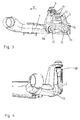
- FIG. 3 shows a side view, in particular, the suspension 5 is identified.
- the pivot bearing 6 is above the in FIG. 3 indicated wheel rotational axis 12, whereas the rubber solid bearing 7a in the direction of travel F in front of the Radcardachse 12 and the rubber-solid bearing 7b in the direction of travel F behind the Radcardachse 12 is arranged.
- the rubber solid bearings 7a, 7b are each coupled via bolt 15 with the longitudinal rocker 3.
- the suspension 5 also has a flange 16, to which a wheel carrier, not shown here, can be coupled.
- the flange portion 16 has for this purpose various mounting holes 17, so that the wheel carrier, not shown, is adjustable.
- FIG. 4 shows a front view of the invention elastically mounted suspension 5, it being noted that these are of a circumferential Reinforcing edge 18 is reinforced in both their flexural rigidity and in their torsional rigidity.
- At the ends of the longitudinal rocker 3 further recordings 19 are provided, to which the non-identifiable rubber solid bearings are coupled.
- the receptacles 19 extend in a funnel shape, so that the largest possible bearing surface not shown here between receptacle 19 and rubber solid bearing 7 is made.
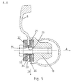
- FIG. 5 further shows a sectional view according to the section line aa FIG. 2 ,
- the receptacle 19 has a funnel-shaped course and has a receiving groove 20 for receiving an internal rubber-solid bearing 21 and an inner rubber-solid bearing 21.
- an outer rubber-solid bearing 22 is shown, wherein between the two rubber-solid bearings 21, 22, the wheel is coupled coupled. Both are penetrated by the bolt, so that a positive coupling to the longitudinal rocker 3 takes place, however, remains on the rubber-solid support elasticity for pivoting the suspension.
- Both the rubber-solid bearing 21 and the rubber-solid bearing 22 each have a collar 35 oriented in the axial direction A on the respective solid material bearing outer disk 33 and 34, respectively.
- the collar 35 and the two outer discs 33, 34 are shown oriented towards each other and engage with the collar 35 in sections in a mounting hole 36 of the suspension 5. This ensures that, in particular in the radial direction 37, a positive fit of the rubber solid bearing 21, 22 is reached and the rubber solid bearing 21, 22 thus can not slip in operation in performing the elastokinematic movement.
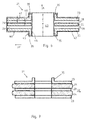
- FIG. 6 shows a rubber solid-state bearing 21 according to the invention with three parallel spaced discs 23.
- the discs 23 may have a distance 38, 39 to each other, wherein the distances 38, 39 may be the same, but may also be different from each other.
- the rubber layer 24 is then arranged in each case between the disks 23, wherein the rubber layer 24 in the axial direction A has a width 40 which corresponds to the respective spacing 38, 39.
- the discs 23 each have a width 41, wherein all discs 23 may have a same width 41 or may have different widths 41 from each other.
- the Width 40 is preferably greater than the width 41. However, the width 40 may also have the same size compared to the width 41 or greater than the width 41.
- the discs 23 themselves may then be formed of metallic material, in particular steel material, but also of plastic material .
- the respective outer discs 23 of this illustrated rubber solid bearing 21 each have a collar 35. Both collars 35 are shown pointing in the opposite axial direction A pointing.
- the entire rubber solid bearing 21 is covered by a rubber jacket 42.
- a bearing 43 passing through the opening is also covered on its inner lateral surface 44 by the rubber jacket 42.
- the outer circumferential surface 45 of the collar 35 is also covered by the rubber jacket 42.
- an outer layer 46 of the rubber jacket 42 and / or the rubber jacket 42 are vulcanized on the outer circumferential surface 45 of the collar 35 in the mounting opening 36 on the suspension 5.
- FIG. 7 shows an embodiment variant of FIG. 6
- the respective rubber layer 24 is biased so that it is formed over the discs 23 in the radial direction 37 projecting.
- FIG. 7 has only on the image plane related to the upper plate 23 a collar 35 and no rubber jacket 42nd
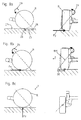
- FIG. 8 show three different forces acting on the wheel R with a motor vehicle axle according to the invention 1.
- a cornering is shown as an example, wherein a negative trailing path 25 between the intersection 9 of the virtual longitudinal axis 13 and the road surface and the Radaufstands composition is formed.
- a lateral force rotation of the wheel R about the virtual longitudinal axis 13 takes place in toe-in.
- FIG. 8b shows the motor vehicle axle 1 according to the invention under the action of a braking force Fx.
- a braking force Fx acts on the wheel R, wherein by a negative steering roller radius 30, formed between the wheel contact point 28 and the intersection of the virtual steering axis in motor vehicle Y direction Y rotation about the steering axis, so that the wheel R undergoes a toe correction.
- FIG. 8c shows the action of a vertical force Fz on the wheel R of a motor vehicle axle 1 according to the invention.
- the wheel R undergoes no relative displacement about the virtual steering axis.
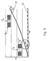
- FIG. 9 shows a spring characteristic of the rubber-solid bearing assembly, wherein the solid line shows the course of the axial stiffness 31 and the dashed line the course of the radial stiffness 32.
- Fa occurs a progressive increase in the axial stiffness 31, whereas only a linear, minimal increase in radial stiffness 32 takes place.
- This can be the ratio of radial to axial stiffness 31, 32 influenced by the bias of the rubber-solid bearing assembly in the installed state on the axis.
Landscapes
- Engineering & Computer Science (AREA)
- General Engineering & Computer Science (AREA)
- Mechanical Engineering (AREA)
- Architecture (AREA)
- Vehicle Body Suspensions (AREA)
- Springs (AREA)
- Vibration Prevention Devices (AREA)
Applications Claiming Priority (1)
| Application Number | Priority Date | Filing Date | Title |
|---|---|---|---|
| DE102015109533.5A DE102015109533B4 (de) | 2015-06-15 | 2015-06-15 | Gummi-Feststofflager zur Anordnung an einer Kraftfahrzeugachse |
Publications (2)
| Publication Number | Publication Date |
|---|---|
| EP3106706A1 true EP3106706A1 (fr) | 2016-12-21 |
| EP3106706B1 EP3106706B1 (fr) | 2018-08-15 |
Family
ID=56116304
Family Applications (1)
| Application Number | Title | Priority Date | Filing Date |
|---|---|---|---|
| EP16173396.9A Active EP3106706B1 (fr) | 2015-06-15 | 2016-06-07 | Un axe de vehicule automobile avec un palier rigide en caoutchouc |
Country Status (5)
| Country | Link |
|---|---|
| US (1) | US9885387B2 (fr) |
| EP (1) | EP3106706B1 (fr) |
| JP (1) | JP6307556B2 (fr) |
| CN (1) | CN106382313B (fr) |
| DE (1) | DE102015109533B4 (fr) |
Families Citing this family (6)
| Publication number | Priority date | Publication date | Assignee | Title |
|---|---|---|---|---|
| DE102014201876A1 (de) * | 2014-02-03 | 2015-08-06 | Schaeffler Technologies AG & Co. KG | Vorrichtung zum Einstellen der Spur und/oder des Sturzes für ein Fahrwerk eines Kraftfahrzeugs |
| DE102016114678A1 (de) * | 2016-08-08 | 2018-02-08 | Thyssenkrupp Ag | Drehlageranordnung für eine Lenksäule eines Kraftfahrzeugs |
| JP6458832B1 (ja) * | 2017-07-26 | 2019-01-30 | マツダ株式会社 | 車両の後部サスペンション構造 |
| DE102018205877B3 (de) * | 2018-04-18 | 2019-10-24 | Ford Global Technologies, Llc | Achse für ein Fahrzeug |
| JP7186812B2 (ja) * | 2021-02-18 | 2022-12-09 | 本田技研工業株式会社 | サスペンション |
| DE102021108655A1 (de) * | 2021-04-07 | 2022-10-13 | Bayerische Motoren Werke Aktiengesellschaft | Achsträgerlagerung für eine, insbesondere mittels Elektromotor angetriebene, Achse eines Kraftfahrzeugs |
Citations (6)
| Publication number | Priority date | Publication date | Assignee | Title |
|---|---|---|---|---|
| US2477972A (en) * | 1945-08-27 | 1949-08-02 | Mb Mfg Company Inc | Vibration isolator unit |
| FR1291303A (fr) * | 1960-06-22 | 1962-04-20 | Gomma Antivibranti Applic | Perfectionnements aux ressorts de compression en caoutchouc-métal |
| DE4141463A1 (de) * | 1991-12-12 | 1993-06-17 | Aeg Schienenfahrzeuge | Radsatzfuehrung, insbesondere fuer schienenfahrzeuge mit drehgestellen |
| EP1887248A1 (fr) * | 2006-08-09 | 2008-02-13 | Franz Mitsch | Ressort multicouche doté d'une rigidité progressive dépendante de la charge |
| WO2010034807A1 (fr) * | 2008-09-26 | 2010-04-01 | M.B. Gerrard V/Miles B. Gerrard | Suspension de véhicule |
| EP2497660A1 (fr) | 2011-03-07 | 2012-09-12 | Benteler Automobiltechnik GmbH | Axe de véhicule automobile doté d'un axe de direction virtuel |
Family Cites Families (24)
| Publication number | Priority date | Publication date | Assignee | Title |
|---|---|---|---|---|
| US2117264A (en) * | 1935-08-06 | 1938-05-10 | Firestone Tire & Rubber Co | Resilient support |
| GB619734A (en) * | 1946-12-23 | 1949-03-14 | George Spencer Moulton & Co | Improvements in and relating to spring units |
| DE1635087U (de) * | 1951-11-23 | 1952-02-28 | Phoenix Metallgummi G M B H | Gummimetall-bauteil. |
| DE885032C (de) * | 1951-12-02 | 1953-07-30 | Metallgummi G M B H | Elastische Rohrverbindung |
| US2749114A (en) * | 1952-03-13 | 1956-06-05 | Miner Inc W H | Rubber cushioning means for shock absorbers |
| US2926881A (en) * | 1958-04-10 | 1960-03-01 | Lord Mfg Co | Resilient mounting |
| DE7325480U (de) * | 1973-07-11 | 1973-10-04 | Hansens Gummi & Packungswerke Kg | Elastische Feder, insbesondere für Fahrzeuge mit Drehgestellen |
| DE2342990C3 (de) * | 1973-08-25 | 1978-10-26 | Daimler-Benz Ag, 7000 Stuttgart | Gleit/Gummi-Torsionslagerung zur Aufnahme von axialen und radialen Kräften |
| US4211429A (en) * | 1978-04-19 | 1980-07-08 | Howard D U | Adjustable suspension assembly |
| JPS58114932U (ja) * | 1982-01-30 | 1983-08-05 | トヨタ自動車株式会社 | 車両用サスペンシヨンブツシユ構造 |
| US5246242A (en) * | 1990-10-05 | 1993-09-21 | Paccar Inc. | Passively steered tandem axle group |
| DE4120772C2 (de) | 1991-06-24 | 1994-11-24 | Lemfoerder Metallwaren Ag | Radial und axial belastbares Drehgleitlager für Fahrwerksteile in Kraftfahrzeugen |
| JP2575076Y2 (ja) | 1993-05-07 | 1998-06-25 | 内山工業株式会社 | ワッシャーシール |
| JPH07332341A (ja) | 1994-06-10 | 1995-12-22 | Uchiyama Mfg Corp | ワッシャーシール |
| US5641153A (en) * | 1995-12-06 | 1997-06-24 | Lord Corporation | Auxiliary damper for rubber suspension mountings |
| JPH09217726A (ja) | 1996-02-13 | 1997-08-19 | Toyo Tire & Rubber Co Ltd | 締結用弾性ワッシャ |
| US6896110B2 (en) * | 2003-09-25 | 2005-05-24 | Tenneco Automotive Operating Company Inc. | Temperature compensated dual acting slip |
| JP2005265165A (ja) | 2004-03-22 | 2005-09-29 | Toyo Tire & Rubber Co Ltd | 積層ゴム支承 |
| JP5373274B2 (ja) * | 2006-09-22 | 2013-12-18 | 株式会社ブリヂストン | 防振構造体 |
| US8196912B2 (en) * | 2008-09-10 | 2012-06-12 | Miner Enterprises, Inc. | Railcar elastomeric spring |
| JP5538957B2 (ja) * | 2010-03-04 | 2014-07-02 | 株式会社ブリヂストン | 防振構造体 |
| JP5595203B2 (ja) * | 2010-09-29 | 2014-09-24 | 東海ゴム工業株式会社 | トーコレクトブッシュ |
| DE102013200524A1 (de) | 2013-01-16 | 2014-07-17 | Zf Friedrichshafen Ag | Pendelstütze |
| CN203666303U (zh) * | 2013-11-22 | 2014-06-25 | 宁波拓普集团股份有限公司 | 一种汽车控制臂橡胶衬套 |
-
2015
- 2015-06-15 DE DE102015109533.5A patent/DE102015109533B4/de not_active Expired - Fee Related
-
2016
- 2016-06-07 EP EP16173396.9A patent/EP3106706B1/fr active Active
- 2016-06-14 JP JP2016117796A patent/JP6307556B2/ja not_active Expired - Fee Related
- 2016-06-14 US US15/181,719 patent/US9885387B2/en not_active Expired - Fee Related
- 2016-06-15 CN CN201610796186.5A patent/CN106382313B/zh active Active
Patent Citations (6)
| Publication number | Priority date | Publication date | Assignee | Title |
|---|---|---|---|---|
| US2477972A (en) * | 1945-08-27 | 1949-08-02 | Mb Mfg Company Inc | Vibration isolator unit |
| FR1291303A (fr) * | 1960-06-22 | 1962-04-20 | Gomma Antivibranti Applic | Perfectionnements aux ressorts de compression en caoutchouc-métal |
| DE4141463A1 (de) * | 1991-12-12 | 1993-06-17 | Aeg Schienenfahrzeuge | Radsatzfuehrung, insbesondere fuer schienenfahrzeuge mit drehgestellen |
| EP1887248A1 (fr) * | 2006-08-09 | 2008-02-13 | Franz Mitsch | Ressort multicouche doté d'une rigidité progressive dépendante de la charge |
| WO2010034807A1 (fr) * | 2008-09-26 | 2010-04-01 | M.B. Gerrard V/Miles B. Gerrard | Suspension de véhicule |
| EP2497660A1 (fr) | 2011-03-07 | 2012-09-12 | Benteler Automobiltechnik GmbH | Axe de véhicule automobile doté d'un axe de direction virtuel |
Also Published As
| Publication number | Publication date |
|---|---|
| JP2017013782A (ja) | 2017-01-19 |
| DE102015109533B4 (de) | 2019-03-21 |
| US20160377118A1 (en) | 2016-12-29 |
| DE102015109533A9 (de) | 2017-03-16 |
| JP6307556B2 (ja) | 2018-04-04 |
| CN106382313B (zh) | 2018-09-25 |
| US9885387B2 (en) | 2018-02-06 |
| EP3106706B1 (fr) | 2018-08-15 |
| DE102015109533A1 (de) | 2016-12-15 |
| CN106382313A (zh) | 2017-02-08 |
Similar Documents
| Publication | Publication Date | Title |
|---|---|---|
| EP2497660B1 (fr) | Axe de véhicule automobile doté d'un axe de direction virtuel | |
| EP3106706B1 (fr) | Un axe de vehicule automobile avec un palier rigide en caoutchouc | |
| EP0494393B1 (fr) | Suspension de roue indépendante | |
| DE102012200001A1 (de) | Gummimetallager für Kraftfahrzeug-Radaufhängung, Trapezlenker und Radaufhängung | |
| EP3452310B1 (fr) | Suspension à roues indépendantes d'un véhicule, dotée d'un élément formant ressort à lame guidant les roues, réalisé dans un matériau composite fibreux | |
| DE102009047404B4 (de) | Radaufhängung | |
| DE102007043121A1 (de) | Verbundlenkerachse mit elastisch aufgehängtem Radträger | |
| DE69808791T2 (de) | Gelenkmittel zwischen zwei verbindungsteilen und kraftfahrzeug mit einer damit ausgerüsteten radaufhängung | |
| EP3153737B1 (fr) | Palier de châssis | |
| DE102018201435B4 (de) | Achsaufhängung | |
| DE102020128606A1 (de) | Vorrichtung zum Lagern einer radführenden Querblattfeder eines Fahrzeuges | |
| DE102014207793B4 (de) | Radaufhängung für ein Fahrzeug | |
| EP2396183A1 (fr) | Suspension de roue pour véhicules automobiles présentant un élément de réglage associé au support de roue pour le réglage d'un angle de pincement et/ou de carrossage | |
| DE102005013374B4 (de) | Halterung für einen um eine Schwenkachse schwenkbaren Lenker einer Radaufhängung eines Fahrzeugs | |
| DE102018207616B4 (de) | Radaufhängung für ein Kraftfahrzeug | |
| DE102012221841B4 (de) | Gummimetalllager für Kraftfahrzeug-Radaufhängung, Trapezlenker und Radaufhängung | |
| DE102015211180B4 (de) | Radaufhängung für ein Kraftfahrzeug | |
| DE102011106797B4 (de) | 1 - 10Schräglenkerachse für ein Kraftfahrzeug | |
| DE3024845A1 (de) | Daempferbeinachse fuer personenkraftwagen | |
| DE102017218795B4 (de) | Achsaufhängung | |
| WO2020221569A1 (fr) | Suspension indépendante pour un véhicule à deux voies, essieu et véhicule | |
| DE102018123443B4 (de) | Achsaufhängung mit Doppelquerlenker | |
| DE102016201251B4 (de) | Radaufhängungsvorrichtung | |
| DE102024117820A1 (de) | Einzelradaufhängung eines Kraftfahrzeugs und Kraftfahrzeug | |
| DE102005043628A1 (de) | Aufhängung für ein Hinterrad eines Fahrzeugs |
Legal Events
| Date | Code | Title | Description |
|---|---|---|---|
| PUAI | Public reference made under article 153(3) epc to a published international application that has entered the european phase |
Free format text: ORIGINAL CODE: 0009012 |
|
| STAA | Information on the status of an ep patent application or granted ep patent |
Free format text: STATUS: THE APPLICATION HAS BEEN PUBLISHED |
|
| AK | Designated contracting states |
Kind code of ref document: A1 Designated state(s): AL AT BE BG CH CY CZ DE DK EE ES FI FR GB GR HR HU IE IS IT LI LT LU LV MC MK MT NL NO PL PT RO RS SE SI SK SM TR |
|
| AX | Request for extension of the european patent |
Extension state: BA ME |
|
| STAA | Information on the status of an ep patent application or granted ep patent |
Free format text: STATUS: REQUEST FOR EXAMINATION WAS MADE |
|
| 17P | Request for examination filed |
Effective date: 20170102 |
|
| STAA | Information on the status of an ep patent application or granted ep patent |
Free format text: STATUS: EXAMINATION IS IN PROGRESS |
|
| 17Q | First examination report despatched |
Effective date: 20170410 |
|
| GRAP | Despatch of communication of intention to grant a patent |
Free format text: ORIGINAL CODE: EPIDOSNIGR1 |
|
| STAA | Information on the status of an ep patent application or granted ep patent |
Free format text: STATUS: GRANT OF PATENT IS INTENDED |
|
| INTG | Intention to grant announced |
Effective date: 20180327 |
|
| GRAS | Grant fee paid |
Free format text: ORIGINAL CODE: EPIDOSNIGR3 |
|
| GRAA | (expected) grant |
Free format text: ORIGINAL CODE: 0009210 |
|
| STAA | Information on the status of an ep patent application or granted ep patent |
Free format text: STATUS: THE PATENT HAS BEEN GRANTED |
|
| AK | Designated contracting states |
Kind code of ref document: B1 Designated state(s): AL AT BE BG CH CY CZ DE DK EE ES FI FR GB GR HR HU IE IS IT LI LT LU LV MC MK MT NL NO PL PT RO RS SE SI SK SM TR |
|
| REG | Reference to a national code |
Ref country code: CH Ref legal event code: EP Ref country code: GB Ref legal event code: FG4D Free format text: NOT ENGLISH Ref country code: AT Ref legal event code: REF Ref document number: 1030146 Country of ref document: AT Kind code of ref document: T Effective date: 20180815 |
|
| REG | Reference to a national code |
Ref country code: IE Ref legal event code: FG4D Free format text: LANGUAGE OF EP DOCUMENT: GERMAN |
|
| REG | Reference to a national code |
Ref country code: DE Ref legal event code: R096 Ref document number: 502016001667 Country of ref document: DE |
|
| REG | Reference to a national code |
Ref country code: NL Ref legal event code: MP Effective date: 20180815 |
|
| REG | Reference to a national code |
Ref country code: LT Ref legal event code: MG4D |
|
| PG25 | Lapsed in a contracting state [announced via postgrant information from national office to epo] |
Ref country code: NL Free format text: LAPSE BECAUSE OF FAILURE TO SUBMIT A TRANSLATION OF THE DESCRIPTION OR TO PAY THE FEE WITHIN THE PRESCRIBED TIME-LIMIT Effective date: 20180815 Ref country code: BG Free format text: LAPSE BECAUSE OF FAILURE TO SUBMIT A TRANSLATION OF THE DESCRIPTION OR TO PAY THE FEE WITHIN THE PRESCRIBED TIME-LIMIT Effective date: 20181115 Ref country code: SE Free format text: LAPSE BECAUSE OF FAILURE TO SUBMIT A TRANSLATION OF THE DESCRIPTION OR TO PAY THE FEE WITHIN THE PRESCRIBED TIME-LIMIT Effective date: 20180815 Ref country code: NO Free format text: LAPSE BECAUSE OF FAILURE TO SUBMIT A TRANSLATION OF THE DESCRIPTION OR TO PAY THE FEE WITHIN THE PRESCRIBED TIME-LIMIT Effective date: 20181115 Ref country code: RS Free format text: LAPSE BECAUSE OF FAILURE TO SUBMIT A TRANSLATION OF THE DESCRIPTION OR TO PAY THE FEE WITHIN THE PRESCRIBED TIME-LIMIT Effective date: 20180815 Ref country code: GR Free format text: LAPSE BECAUSE OF FAILURE TO SUBMIT A TRANSLATION OF THE DESCRIPTION OR TO PAY THE FEE WITHIN THE PRESCRIBED TIME-LIMIT Effective date: 20181116 Ref country code: LT Free format text: LAPSE BECAUSE OF FAILURE TO SUBMIT A TRANSLATION OF THE DESCRIPTION OR TO PAY THE FEE WITHIN THE PRESCRIBED TIME-LIMIT Effective date: 20180815 Ref country code: IS Free format text: LAPSE BECAUSE OF FAILURE TO SUBMIT A TRANSLATION OF THE DESCRIPTION OR TO PAY THE FEE WITHIN THE PRESCRIBED TIME-LIMIT Effective date: 20181215 Ref country code: FI Free format text: LAPSE BECAUSE OF FAILURE TO SUBMIT A TRANSLATION OF THE DESCRIPTION OR TO PAY THE FEE WITHIN THE PRESCRIBED TIME-LIMIT Effective date: 20180815 |
|
| PG25 | Lapsed in a contracting state [announced via postgrant information from national office to epo] |
Ref country code: LV Free format text: LAPSE BECAUSE OF FAILURE TO SUBMIT A TRANSLATION OF THE DESCRIPTION OR TO PAY THE FEE WITHIN THE PRESCRIBED TIME-LIMIT Effective date: 20180815 Ref country code: AL Free format text: LAPSE BECAUSE OF FAILURE TO SUBMIT A TRANSLATION OF THE DESCRIPTION OR TO PAY THE FEE WITHIN THE PRESCRIBED TIME-LIMIT Effective date: 20180815 Ref country code: HR Free format text: LAPSE BECAUSE OF FAILURE TO SUBMIT A TRANSLATION OF THE DESCRIPTION OR TO PAY THE FEE WITHIN THE PRESCRIBED TIME-LIMIT Effective date: 20180815 |
|
| PG25 | Lapsed in a contracting state [announced via postgrant information from national office to epo] |
Ref country code: IT Free format text: LAPSE BECAUSE OF FAILURE TO SUBMIT A TRANSLATION OF THE DESCRIPTION OR TO PAY THE FEE WITHIN THE PRESCRIBED TIME-LIMIT Effective date: 20180815 Ref country code: PL Free format text: LAPSE BECAUSE OF FAILURE TO SUBMIT A TRANSLATION OF THE DESCRIPTION OR TO PAY THE FEE WITHIN THE PRESCRIBED TIME-LIMIT Effective date: 20180815 Ref country code: ES Free format text: LAPSE BECAUSE OF FAILURE TO SUBMIT A TRANSLATION OF THE DESCRIPTION OR TO PAY THE FEE WITHIN THE PRESCRIBED TIME-LIMIT Effective date: 20180815 Ref country code: EE Free format text: LAPSE BECAUSE OF FAILURE TO SUBMIT A TRANSLATION OF THE DESCRIPTION OR TO PAY THE FEE WITHIN THE PRESCRIBED TIME-LIMIT Effective date: 20180815 Ref country code: CZ Free format text: LAPSE BECAUSE OF FAILURE TO SUBMIT A TRANSLATION OF THE DESCRIPTION OR TO PAY THE FEE WITHIN THE PRESCRIBED TIME-LIMIT Effective date: 20180815 Ref country code: RO Free format text: LAPSE BECAUSE OF FAILURE TO SUBMIT A TRANSLATION OF THE DESCRIPTION OR TO PAY THE FEE WITHIN THE PRESCRIBED TIME-LIMIT Effective date: 20180815 |
|
| REG | Reference to a national code |
Ref country code: DE Ref legal event code: R097 Ref document number: 502016001667 Country of ref document: DE |
|
| PG25 | Lapsed in a contracting state [announced via postgrant information from national office to epo] |
Ref country code: SM Free format text: LAPSE BECAUSE OF FAILURE TO SUBMIT A TRANSLATION OF THE DESCRIPTION OR TO PAY THE FEE WITHIN THE PRESCRIBED TIME-LIMIT Effective date: 20180815 Ref country code: DK Free format text: LAPSE BECAUSE OF FAILURE TO SUBMIT A TRANSLATION OF THE DESCRIPTION OR TO PAY THE FEE WITHIN THE PRESCRIBED TIME-LIMIT Effective date: 20180815 Ref country code: SK Free format text: LAPSE BECAUSE OF FAILURE TO SUBMIT A TRANSLATION OF THE DESCRIPTION OR TO PAY THE FEE WITHIN THE PRESCRIBED TIME-LIMIT Effective date: 20180815 |
|
| PLBE | No opposition filed within time limit |
Free format text: ORIGINAL CODE: 0009261 |
|
| STAA | Information on the status of an ep patent application or granted ep patent |
Free format text: STATUS: NO OPPOSITION FILED WITHIN TIME LIMIT |
|
| 26N | No opposition filed |
Effective date: 20190516 |
|
| PG25 | Lapsed in a contracting state [announced via postgrant information from national office to epo] |
Ref country code: SI Free format text: LAPSE BECAUSE OF FAILURE TO SUBMIT A TRANSLATION OF THE DESCRIPTION OR TO PAY THE FEE WITHIN THE PRESCRIBED TIME-LIMIT Effective date: 20180815 |
|
| PG25 | Lapsed in a contracting state [announced via postgrant information from national office to epo] |
Ref country code: MC Free format text: LAPSE BECAUSE OF FAILURE TO SUBMIT A TRANSLATION OF THE DESCRIPTION OR TO PAY THE FEE WITHIN THE PRESCRIBED TIME-LIMIT Effective date: 20180815 |
|
| REG | Reference to a national code |
Ref country code: CH Ref legal event code: PL |
|
| REG | Reference to a national code |
Ref country code: BE Ref legal event code: MM Effective date: 20190630 |
|
| PG25 | Lapsed in a contracting state [announced via postgrant information from national office to epo] |
Ref country code: TR Free format text: LAPSE BECAUSE OF FAILURE TO SUBMIT A TRANSLATION OF THE DESCRIPTION OR TO PAY THE FEE WITHIN THE PRESCRIBED TIME-LIMIT Effective date: 20180815 |
|
| PG25 | Lapsed in a contracting state [announced via postgrant information from national office to epo] |
Ref country code: IE Free format text: LAPSE BECAUSE OF NON-PAYMENT OF DUE FEES Effective date: 20190607 |
|
| PG25 | Lapsed in a contracting state [announced via postgrant information from national office to epo] |
Ref country code: CH Free format text: LAPSE BECAUSE OF NON-PAYMENT OF DUE FEES Effective date: 20190630 Ref country code: LU Free format text: LAPSE BECAUSE OF NON-PAYMENT OF DUE FEES Effective date: 20190607 Ref country code: LI Free format text: LAPSE BECAUSE OF NON-PAYMENT OF DUE FEES Effective date: 20190630 Ref country code: BE Free format text: LAPSE BECAUSE OF NON-PAYMENT OF DUE FEES Effective date: 20190630 |
|
| PG25 | Lapsed in a contracting state [announced via postgrant information from national office to epo] |
Ref country code: PT Free format text: LAPSE BECAUSE OF FAILURE TO SUBMIT A TRANSLATION OF THE DESCRIPTION OR TO PAY THE FEE WITHIN THE PRESCRIBED TIME-LIMIT Effective date: 20181215 |
|
| PGFP | Annual fee paid to national office [announced via postgrant information from national office to epo] |
Ref country code: FR Payment date: 20200619 Year of fee payment: 5 |
|
| PGFP | Annual fee paid to national office [announced via postgrant information from national office to epo] |
Ref country code: GB Payment date: 20200625 Year of fee payment: 5 |
|
| PG25 | Lapsed in a contracting state [announced via postgrant information from national office to epo] |
Ref country code: CY Free format text: LAPSE BECAUSE OF FAILURE TO SUBMIT A TRANSLATION OF THE DESCRIPTION OR TO PAY THE FEE WITHIN THE PRESCRIBED TIME-LIMIT Effective date: 20180815 |
|
| PG25 | Lapsed in a contracting state [announced via postgrant information from national office to epo] |
Ref country code: MT Free format text: LAPSE BECAUSE OF FAILURE TO SUBMIT A TRANSLATION OF THE DESCRIPTION OR TO PAY THE FEE WITHIN THE PRESCRIBED TIME-LIMIT Effective date: 20180815 Ref country code: HU Free format text: LAPSE BECAUSE OF FAILURE TO SUBMIT A TRANSLATION OF THE DESCRIPTION OR TO PAY THE FEE WITHIN THE PRESCRIBED TIME-LIMIT; INVALID AB INITIO Effective date: 20160607 |
|
| GBPC | Gb: european patent ceased through non-payment of renewal fee |
Effective date: 20210607 |
|
| PG25 | Lapsed in a contracting state [announced via postgrant information from national office to epo] |
Ref country code: GB Free format text: LAPSE BECAUSE OF NON-PAYMENT OF DUE FEES Effective date: 20210607 |
|
| PG25 | Lapsed in a contracting state [announced via postgrant information from national office to epo] |
Ref country code: FR Free format text: LAPSE BECAUSE OF NON-PAYMENT OF DUE FEES Effective date: 20210630 |
|
| PG25 | Lapsed in a contracting state [announced via postgrant information from national office to epo] |
Ref country code: MK Free format text: LAPSE BECAUSE OF FAILURE TO SUBMIT A TRANSLATION OF THE DESCRIPTION OR TO PAY THE FEE WITHIN THE PRESCRIBED TIME-LIMIT Effective date: 20180815 |
|
| REG | Reference to a national code |
Ref country code: AT Ref legal event code: MM01 Ref document number: 1030146 Country of ref document: AT Kind code of ref document: T Effective date: 20210607 |
|
| PG25 | Lapsed in a contracting state [announced via postgrant information from national office to epo] |
Ref country code: AT Free format text: LAPSE BECAUSE OF NON-PAYMENT OF DUE FEES Effective date: 20210607 |
|
| PGFP | Annual fee paid to national office [announced via postgrant information from national office to epo] |
Ref country code: DE Payment date: 20250627 Year of fee payment: 10 |