EP3119960B1 - Lattenbefestigungssystem zur bildung eines bodenbelags oder eines doppelbodens - Google Patents
Lattenbefestigungssystem zur bildung eines bodenbelags oder eines doppelbodens Download PDFInfo
- Publication number
- EP3119960B1 EP3119960B1 EP15725700.7A EP15725700A EP3119960B1 EP 3119960 B1 EP3119960 B1 EP 3119960B1 EP 15725700 A EP15725700 A EP 15725700A EP 3119960 B1 EP3119960 B1 EP 3119960B1
- Authority
- EP
- European Patent Office
- Prior art keywords
- channel
- slats
- soleplate
- securing
- fasteners
- Prior art date
- Legal status (The legal status is an assumption and is not a legal conclusion. Google has not performed a legal analysis and makes no representation as to the accuracy of the status listed.)
- Active
Links
Images

Classifications
-
- E—FIXED CONSTRUCTIONS
- E04—BUILDING
- E04F—FINISHING WORK ON BUILDINGS, e.g. STAIRS, FLOORS
- E04F15/00—Flooring
- E04F15/02—Flooring or floor layers composed of a number of similar elements
- E04F15/02038—Flooring or floor layers composed of a number of similar elements characterised by tongue and groove connections between neighbouring flooring elements
-
- E—FIXED CONSTRUCTIONS
- E04—BUILDING
- E04B—GENERAL BUILDING CONSTRUCTIONS; WALLS, e.g. PARTITIONS; ROOFS; FLOORS; CEILINGS; INSULATION OR OTHER PROTECTION OF BUILDINGS
- E04B5/00—Floors; Floor construction with regard to insulation; Connections specially adapted therefor
- E04B5/02—Load-carrying floor structures formed substantially of prefabricated units
- E04B5/023—Separate connecting devices for prefabricated floor-slabs
-
- E—FIXED CONSTRUCTIONS
- E04—BUILDING
- E04F—FINISHING WORK ON BUILDINGS, e.g. STAIRS, FLOORS
- E04F15/00—Flooring
- E04F15/02—Flooring or floor layers composed of a number of similar elements
- E04F15/02044—Separate elements for fastening to an underlayer
-
- E—FIXED CONSTRUCTIONS
- E04—BUILDING
- E04B—GENERAL BUILDING CONSTRUCTIONS; WALLS, e.g. PARTITIONS; ROOFS; FLOORS; CEILINGS; INSULATION OR OTHER PROTECTION OF BUILDINGS
- E04B1/00—Constructions in general; Structures which are not restricted either to walls, e.g. partitions, or floors or ceilings or roofs
- E04B1/003—Balconies; Decks
- E04B1/0038—Anchoring devices specially adapted therefor with means for preventing cold bridging
-
- E—FIXED CONSTRUCTIONS
- E04—BUILDING
- E04F—FINISHING WORK ON BUILDINGS, e.g. STAIRS, FLOORS
- E04F13/00—Coverings or linings, e.g. for walls or ceilings
- E04F13/07—Coverings or linings, e.g. for walls or ceilings composed of covering or lining elements; Sub-structures therefor; Fastening means therefor
- E04F13/08—Coverings or linings, e.g. for walls or ceilings composed of covering or lining elements; Sub-structures therefor; Fastening means therefor composed of a plurality of similar covering or lining elements
- E04F13/0801—Separate fastening elements
- E04F13/0803—Separate fastening elements with load-supporting elongated furring elements between wall and covering elements
- E04F13/081—Separate fastening elements with load-supporting elongated furring elements between wall and covering elements with additional fastening elements between furring elements and covering elements
- E04F13/0816—Separate fastening elements with load-supporting elongated furring elements between wall and covering elements with additional fastening elements between furring elements and covering elements the additional fastening elements extending into the back side of the covering elements
- E04F13/0819—Separate fastening elements with load-supporting elongated furring elements between wall and covering elements with additional fastening elements between furring elements and covering elements the additional fastening elements extending into the back side of the covering elements inserted into grooves in the back side of the covering elements
-
- E—FIXED CONSTRUCTIONS
- E04—BUILDING
- E04F—FINISHING WORK ON BUILDINGS, e.g. STAIRS, FLOORS
- E04F15/00—Flooring
- E04F15/02—Flooring or floor layers composed of a number of similar elements
- E04F15/02177—Floor elements for use at a specific location
- E04F15/02183—Floor elements for use at a specific location for outdoor use, e.g. in decks, patios, terraces, verandas or the like
-
- E—FIXED CONSTRUCTIONS
- E04—BUILDING
- E04F—FINISHING WORK ON BUILDINGS, e.g. STAIRS, FLOORS
- E04F15/00—Flooring
- E04F15/02—Flooring or floor layers composed of a number of similar elements
- E04F15/024—Sectional false floors, e.g. computer floors
- E04F15/02447—Supporting structures
- E04F15/02458—Framework supporting the panels
-
- E—FIXED CONSTRUCTIONS
- E04—BUILDING
- E04F—FINISHING WORK ON BUILDINGS, e.g. STAIRS, FLOORS
- E04F15/00—Flooring
- E04F15/02—Flooring or floor layers composed of a number of similar elements
- E04F15/02044—Separate elements for fastening to an underlayer
- E04F2015/0205—Separate elements for fastening to an underlayer with load-supporting elongated furring elements between the flooring elements and the underlayer
- E04F2015/02066—Separate elements for fastening to an underlayer with load-supporting elongated furring elements between the flooring elements and the underlayer with additional fastening elements between furring elements and flooring elements
- E04F2015/02072—Separate elements for fastening to an underlayer with load-supporting elongated furring elements between the flooring elements and the underlayer with additional fastening elements between furring elements and flooring elements the additional fastening elements extending into the back side of the flooring elements
-
- E—FIXED CONSTRUCTIONS
- E04—BUILDING
- E04F—FINISHING WORK ON BUILDINGS, e.g. STAIRS, FLOORS
- E04F15/00—Flooring
- E04F15/02—Flooring or floor layers composed of a number of similar elements
- E04F15/02044—Separate elements for fastening to an underlayer
- E04F2015/0205—Separate elements for fastening to an underlayer with load-supporting elongated furring elements between the flooring elements and the underlayer
- E04F2015/02066—Separate elements for fastening to an underlayer with load-supporting elongated furring elements between the flooring elements and the underlayer with additional fastening elements between furring elements and flooring elements
- E04F2015/021—Separate elements for fastening to an underlayer with load-supporting elongated furring elements between the flooring elements and the underlayer with additional fastening elements between furring elements and flooring elements fixed by means of hooking means on the back side of the flooring elements
-
- E—FIXED CONSTRUCTIONS
- E04—BUILDING
- E04F—FINISHING WORK ON BUILDINGS, e.g. STAIRS, FLOORS
- E04F2201/00—Joining sheets or plates or panels
- E04F2201/04—Other details of tongues or grooves
- E04F2201/042—Other details of tongues or grooves with grooves positioned on the rear-side of the panel
Definitions
- the present invention relates to a system for fixing slats or juxtaposed slats to form a raised ground or floor, for example a terrace, or more generally a deck, said slats then being fixed on a support structure which can be based on elements joists or joists type parallels oriented perpendicular to the axis of said slats.
- a support structure which can be based on elements joists or joists type parallels oriented perpendicular to the axis of said slats.
- Such systems are known for example from DE 20 2007 002282 U1 or WO 2006/011173 A1 and describe the features of the preamble of claim 1.
- Fasteners are arranged in rows on said supports, in order to fix the juxtaposed slats according to a schedule of parallel pace. These fasteners are designed to replace the traditional screw fixing, which is restrictive insofar as it requires, among other things, precise measurements, pre-drilling, additional drilling to drown the screw heads, etc.
- the realization of a decking by screwing is also long and tedious, the screwing operations having to be carried out individually.
- another drawback of this type of mounting is of an aesthetic nature, since the screws remain visible on the surface of the decking.
- certain fasteners provided in an elastic material, comprise a first part forming a base and intended to be fixed on the upper surface of the joists or joists, and a second part having an appearance perpendicular to the previous one forming a sort of tenon. intended to be clipped elastically in recesses or mortises made in the slats.
- each of these fasteners - often made of plastic - must then in practice be unscrewed individually, for example for maintenance operations or for recycling. It is a restrictive approach which can prove dissuasive.
- the juxtaposed slat fixing system of the present invention overcomes these various shortcomings, by proposing a design which provides effective protection of the support structure in particular against rot and fungi and thus improves the durability of the wood. It also greatly facilitates the fixing and dismantling of the slats and fasteners, allows functional play in the event of deformation of the slats and finally guarantees the constancy of important geometric parameters such as flatness, etc.
- the invention as defined in claim 1, is essentially characterized in that the fastening system comprises a plurality of waterproof profiles arranged in parallel for a flat floor, or on the basis of an impermeable profile for each support of joist or joist type and then covering the upper surface of said support, removable securing means and positioning means being provided on the profile and on the fasteners made of a flexible elastic material, said positioning means allowing play in the direction of the axis of the profile.
- This profile for example made of aluminum, is therefore rigid and impervious to precipitation, and forms a cover for protecting the wood of the supports, in particular of its upper part which is subjected primarily to bad weather. Given the manufacturing processes for this type of profile, for example by extrusion, straightness and flatness are guaranteed.
- the means for securing the attachments to said profile being removable, they are easily removable.
- This structure also solves the problem of the distribution of the slats, since the positioning means are provided in advance, moreover adapted to the particular technical context of wooden slats which can deform, an axial adjustment of the fasteners being possible. These characteristics give the whole an unequaled ease and flexibility of use.
- spacers provide the interface with said floor, for example hard rubber wedges.
- each profile can have two lateral slides shaped to cooperate with at least two tabs forming a hook protruding from the sole of each fastener in the vicinity of its longitudinal ends, which are clipped elastically in said slides when said sole rests on the upper surface of the streamlined.
- the fasteners are fixed in practice transversely to the profile, the fastening means being therefore close to the two ends of each fastener.
- Removability stems in particular from the elastic nature of the material constituting the fasteners, which allows the main body of the fastener to flex as much as, more locally, the fixing lugs.
- said tabs extend from crosspieces connecting the edges of rectangular-shaped openings made in the sole, said crosspieces being oriented along the axis of the profile. Due to the flexible material of the fasteners, the crosspieces can undergo a certain torsion which, combined with the bending of the legs is taken advantage of during the assembly and disassembly phases.
- the tabs comprise, on their face opposite to that provided at the free end of a projecting profile constituting the hook, a fin, the lower profile of which protrudes from the sole and includes a rectangular-shaped cutout. It is this cutout which is used to insert a disassembly tool aiming to pivot the latching tab to unclip it, as will be explained in more detail below.
- the positioning means comprise at least two studs protruding from the sole, designed to be inserted in positioning holes provided in the upper surface of the profile, said studs being located on either side of two planes of the longitudinal and transverse attachment respectively.
- the fasteners have in fact almost a symmetry of central axis crossing perpendicularly the sole and passing through its geometric center, and defined by the two planes above.
- the studs can be two in number, each connected by a tongue to a first edge of an opening of the sole which is on the one hand in shape parallel to the axis of the profile and on the other hand proximal of a transverse median plane of the fastener, each stud being placed in the vicinity of a second edge of the opening of shape perpendicular to the first edge.
- This tongue flexible since it is made of the material of the fastener, allows axial play in the event of expansion or transverse contraction of the slats of the decking. The play is however limited by the proximity of the second edge which in fact constitutes a stop.
- the upper surface of the profile comprises a flat central rail on which the fasteners rest, surmounting two flat portions lateral placed at a distance from the upper surface of the rail at least equal to the projection of the legs and fins from the lower surface of the sole.
- Said profile may also be provided, in a transverse direction, with returns capable of covering part of the vertical faces of supports of the joist type, the protection of the wood being thereby improved since the coverage is increased.
- the runoff water can then flow without risk of stagnation on parts of the wood with a horizontal appearance.
- a central axial groove of substantially rectangular section is formed in the upper surface of the central rail of the profile, said groove being provided on its walls facing a vertical appearance with a linear thread oriented parallel to the surface of the profile.
- the fasteners themselves include a through hole centered in a transverse direction of the profile, relative to said groove. It is then possible to fix the fasteners to the profile more permanently, using a screw passing through the through hole and the threads of which come into engagement with the linear thread of the central groove. The fixing is then no longer only ensured by clipping, which however performs the initial positioning.
- the central rail of the profile also comprises, on either side of the central groove, two lateral grooves of rectangular-shaped section of width at least equal to the diameter of the studs, the upper opening of which is partially closed by re-entrant flanges separated by a slot, in which are provided holes for positioning the studs.
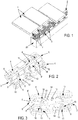
- the slat fixing system (1) of the invention consists of a profile (2) surmounting a joist (20) on which are arranged transversely fasteners (3) in principle regularly spaced.
- attachments consist of two main parts, a sole (4) intended to come into abutment against the upper part of the profile (2), projecting from which deploys substantially perpendicularly a fixing portion (5), the upper part of which comprises oblique lateral flaps (6, 6 '), in the form of an arrow in cross section, said portion (5) being shaped to clip into recesses of corresponding shapes (7) provided in the lower surface of the slats (1) in a way known per se.
- the sole (4) On either side of the portion (5), the sole (4) has openings (8) of rectangular appearance barred with crosspieces (9) to which are fixed tabs (10) whose end is provided in shape hook (11) (see in particular in figure 3 ). These tabs (10) protrude from the lower surface of the sole (4), which moreover comprises an orifice (12) allowing, where appropriate, to screw the fastener (3) to the profile (2).
- Studs (13) appear in two windows (8) located diagonally in the sole (4). These studs are connected via a tab (14) at the short sides of the openings (8) proximal to the transverse median plane of the fasteners (3), but in the immediate vicinity of a large side.
- the tabs (10) have, on their face opposite to that which has the hook-shaped end portion (11), a fin (15), the lower profile of which has a cutout (16) of rectangular shape.
- the profile (2) comprises a central rail (17) provided with three parallel grooves, a central groove (18) and two lateral grooves (19, 21). These grooves are rectangular in section, and the central groove (18) has a linear thread on its two sides, moreover vertical.
- This central rail is framed, in cross section, by two flat portions in which the legs (10) / fins (15) are deployed.
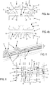
- the thread of the central groove (18) allows, if necessary, to fix the tab (3) using a screw inserted in the orifice (12) and which can then be fixed in the linear thread when the tab ( 3) is in the inserted position, as shown in figure 4b , that is to say with the lower surface of the sole (4) in contact with the upper surface of the rail (17).
- the figure 4a shows the clip (3) before its insertion, the arrows showing the direction and direction of the force to be applied to the clip (3) to clip it onto the profile (2).
- the passage from one to the other involves the clipping of the tabs (10) and their hooks (11) in lateral slides (22, 23) of the central rail (17).
- the hook portions (11), as well as the upper part of the side rails (22, 23) have a bevelled or oblique surface allowing, like a cam, the sliding and then the bending of the legs (10) in order to their clipping inside the slides (21, 22).
- the studs (13) are inserted into pre-drilled orifices (24), at regular intervals, in the grooves (19, 20), as shown in figure 5 .
- the fasteners (3) in the profile (2) is therefore particularly precise.
- the fasteners (3) have the possibility of lateral play, as shown in figure 6 .
- the arrows appearing on this figure 6 show the direction of contraction or expansion of the slats, allowing the tongues (14) to bend until they come into abutment against the edge of the openings (8) near which the studs (13) are located. These edges limit bending and form a stop for movement and therefore possible play.
- the tongues (14) can therefore be deformed in order to allow the fasteners (3) to slide slightly along the profile, thereby preventing deterioration of said fasteners (3) when the wood deforms.
- the additional advantage of limiting the stroke due to the proximity of the studs (13) with the edge of the openings (8) lies in the fact that the wood is kept, despite its expansion or retraction, close to its position. predefined, which is important in the more general setting and management of decking.
- the figure 7 shows the shape that a disassembly tool (25) can take with an upper part for manipulation by the user and a lower segment (26) intended to come into engagement with the cutouts (16) of the fins (15) .
- the segment (26) is inserted into a gap separating two adjacent slats (1), then the tool is rotated by 90 ° before placing it in the cutout (16) which protrudes under the sole (4) as is clearly shown in figure 4b .
- This movement is possible due to the existence of the offset between the upper surface of the central rail (17) of the profile (2) and the flat portions in which the legs (10) and the fins (15) are deployed.
- the profile (2) for example made of extruded aluminum, is therefore rigid, while the fasteners (3) must obviously be made of a flexible and elastic material so that all the manipulations described are possible.
Landscapes
- Engineering & Computer Science (AREA)
- Architecture (AREA)
- Civil Engineering (AREA)
- Structural Engineering (AREA)
- Physics & Mathematics (AREA)
- Electromagnetism (AREA)
- General Engineering & Computer Science (AREA)
- Floor Finish (AREA)
- Road Paving Structures (AREA)
- Mutual Connection Of Rods And Tubes (AREA)
- Shovels (AREA)
Claims (11)
- System für die demontierbare Befestigung von aneinandergereihten Latten (1), um einen Boden beispielsweise einer Terrasse zu bilden, aufweisend Halterungen (3), die in Reihen auf Unterlagen vom Typ ebener Boden oder Balken- oder Trägerstruktur (20) angeordnet sind, die senkrecht zur Achse der Latten (1) ausgerichtet sind, wobei die Halterungen (3) eine Sohle (4) aufweisen, die mit Befestigungsmitteln an den Latten (1) versehen ist,
wobei das System eine Vielzahl undurchlässiger Profile (2) aufweist, die für einen ebenen Boden parallel angeordnet sind, oder in einer Menge von einem undurchlässigen Profil (2) für jede Unterlage (20) vom Typ Balken oder Träger und dann die obere Oberfläche der Unterlage (20) bedecken, dadurch gekennzeichnet, dass die Sohle (4), die zur Abstützung auf einem oberen Teil des Profils (2) bestimmt ist, lösbare Mittel zur festen Befestigung am Profil aufweist, aufweisend mindestens zwei Füße (10), die einen Haken (11) bilden, die über die Sohle (4) herausstehen und die in seitliche Gleitschienen (22, 23) jedes Profils (2) einrasten und Positionierungsmittel auf dem Profil (2), die von mindestens zwei Stiften (13) gebildet sind, die über die Sohle (4) herausstehen und sich in Positionierungslöcher (24) in der oberen Oberfläche des Profils (2) einfügen, wobei die Halterungen (3) aus einem elastischen flexiblen Material gebildet sind, so dass die mit der Sohle (4) verbundenen Stifte (13) ein Spiel in der Richtung der Achse des Profils (2) erlauben. - System zur Befestigung von aneinandergereihten Latten (1) nach vorangehendem Anspruch, dadurch gekennzeichnet, dass jedes Profil (2) zwei seitliche Gleitschienen (22, 23) aufweist, die ausgebildet sind, um mit zwei hakenbildenden Füßen (10) zusammenzuwirken, die über die untere Oberfläche der Sohle (4) jeder Halterung (3) in der Nähe ihrer Längsenden herausstehen, die elastisch in den Gleitschienen (22, 23) einrasten, wenn die Sohle (4) auf der oberen Oberfläche des Profils (2) ruht.
- System zur Befestigung von aneinandergereihten Latten (1) nach vorangehendem Anspruch, dadurch gekennzeichnet, dass sich die Füße (10) ab Traversen (9) erstrecken, die die Ränder rechteckiger Öffnungen (8) verbinden, die in die Sohle (4) eingearbeitet sind, wobei die Traversen (9) in der Achse des Profils (2) ausgerichtet sind.
- System zur Befestigung von aneinandergereihten Latten (1) nach vorangehendem Anspruch, dadurch gekennzeichnet, dass die Füße (10) auf ihrer Fläche gegenüber derjenigen, die im Bereich des freien Endes mit einem hervorstehenden Profil versehen ist, das den Haken (11) bildet, einen Flügel (15) aufweisen, dessen unteres Profil über die Sohle (4) heraussteht und einen rechteckigen Ausschnitt (16) umfasst.
- System zur Befestigung von aneinandergereihten Latten (1) nach einem der vorangehenden Ansprüche, dadurch gekennzeichnet, dass die Positionierungsmittel zwei Stifte (13) aufweisen, die über die unteren Oberfläche der Sohle (4) herausstehen, die zum Einfügen in Positionierungslöcher (24) vorgesehen sind, die in der oberen Oberfläche des Profils (2) vorgesehen sind, wobei sich die Stifte (13) beiderseits von zwei Mittelebenen der Halterung (3) jeweils längs und quer befinden.
- System zur Befestigung von aneinandergereihten Latten (1) nach einem der Ansprüche 3 bis 5, dadurch gekennzeichnet, dass die Stifte (13) zwei an der Zahl sind, wobei jeder mittels einer Zunge (14) mit einem ersten Rand einer Öffnung (8) der Sohle verbunden ist, der zum einen parallel zur Achse des Profils (2) und zum anderen proximal zu einer transversalen Mittelebene der Halterung (3) ist, wobei jeder Stift (13) in der Nähe eines zweiten Randes der Öffnung (8) senkrecht zum ersten Rand platziert ist.
- System zur Befestigung von aneinandergereihten Latten (1) nach einem der Ansprüche 4 bis 6, dadurch gekennzeichnet, dass die obere Oberfläche des Profils (2) eine ebene zentrale Schiene (17) aufweist, auf der die Halterungen (3) ruhen, zwei seitliche ebene Abschnitte überragend, die in einem Abstand von der oberen Oberfläche der Schiene (2) platziert sind, der mindestens gleich dem Vorsprung der Füße (10) und Flügel (15) ab der unteren Oberfläche der Sohle (4) ist.
- System zur Befestigung von aneinandergereihten Latten (1) nach einem der vorangehenden Ansprüche, dadurch gekennzeichnet, dass das Profil (2) in einer transversalen Richtung mit Rücksprüngen versehen ist, die imstande sind, einen Teil der vertikalen Flächen der Unterlagen (20) zu bedecken.
- System zur Befestigung von aneinandergereihten Latten nach einem der Ansprüche 7 und 8, dadurch gekennzeichnet, dass eine zentrale axiale Nut (18) mit etwa rechteckigem Querschnitt in die obere Oberfläche der zentralen Schiene (17) eingearbeitet ist, wobei die Nut (18) auf ihren gegenüberliegenden vertikalen Wänden mit einem linearen Gewinde versehen ist, das parallel zur Oberfläche des Profils (2) ausgerichtet ist.
- System zur Befestigung von aneinandergereihten Latten (1) nach einem der Ansprüche 7 bis 9, dadurch gekennzeichnet, dass die zentrale Schiene (17) des Profils (2) beiderseits der zentralen Nut (18) zwei seitliche Nuten (19, 21) mit rechteckigem Querschnitt einer Breite aufweist, die mindestens gleich dem Durchmesser der Stifte (13) ist, deren obere Öffnung durch eintretende, durch einen Schlitz getrennte Kanten teilweise verschlossen ist, in die Positionierungsöffnungen (24) der Stifte (13) eingearbeitet sind.
- System zur Befestigung von aneinandergereihten Latten (1) nach einem der vorangehenden Ansprüche, dadurch gekennzeichnet, dass die Halterungen (3) eine zentrierte Durchgangsöffnung (12) in einer transversalen Richtung des Profils (2) in Bezug auf die Nut umfassen.
Priority Applications (2)
| Application Number | Priority Date | Filing Date | Title |
|---|---|---|---|
| PL15725700T PL3119960T3 (pl) | 2014-03-21 | 2015-03-19 | System mocowania łat dla utworzenia podniesionej podłogi lub posadzki |
| HRP20201359TT HRP20201359T1 (hr) | 2014-03-21 | 2015-03-19 | Sustav za pričvršćivanje letvica za oblikovanje podne površine ili podignutih podova |
Applications Claiming Priority (2)
| Application Number | Priority Date | Filing Date | Title |
|---|---|---|---|
| FR1452398A FR3018838B1 (fr) | 2014-03-21 | 2014-03-21 | Systeme de fixation de lattes pour former un sol ou plancher rehausse. |
| PCT/FR2015/050685 WO2015140475A1 (fr) | 2014-03-21 | 2015-03-19 | Système de fixation de lattes pour former un sol ou un plancher rehaussé |
Publications (2)
| Publication Number | Publication Date |
|---|---|
| EP3119960A1 EP3119960A1 (de) | 2017-01-25 |
| EP3119960B1 true EP3119960B1 (de) | 2020-05-27 |
Family
ID=51225659
Family Applications (1)
| Application Number | Title | Priority Date | Filing Date |
|---|---|---|---|
| EP15725700.7A Active EP3119960B1 (de) | 2014-03-21 | 2015-03-19 | Lattenbefestigungssystem zur bildung eines bodenbelags oder eines doppelbodens |
Country Status (19)
| Country | Link |
|---|---|
| US (1) | US10119273B2 (de) |
| EP (1) | EP3119960B1 (de) |
| JP (1) | JP6671293B2 (de) |
| CN (1) | CN106661891B (de) |
| AU (2) | AU2015233239A1 (de) |
| BR (1) | BR112016020954B1 (de) |
| CA (1) | CA2943485C (de) |
| DK (1) | DK3119960T3 (de) |
| ES (1) | ES2810157T3 (de) |
| FR (1) | FR3018838B1 (de) |
| HR (1) | HRP20201359T1 (de) |
| HU (1) | HUE050943T2 (de) |
| IL (1) | IL247519A0 (de) |
| LT (1) | LT3119960T (de) |
| MA (2) | MA39473B1 (de) |
| PL (1) | PL3119960T3 (de) |
| PT (1) | PT3119960T (de) |
| RU (1) | RU2683732C2 (de) |
| WO (1) | WO2015140475A1 (de) |
Cited By (4)
| Publication number | Priority date | Publication date | Assignee | Title |
|---|---|---|---|---|
| WO2025233309A1 (en) | 2024-05-06 | 2025-11-13 | Van Der Valk Systemen B.V. | Fastening element, modular system comprising such a fastening element and method for assembling and disassembling such modular system |
| WO2026005599A1 (en) * | 2024-06-27 | 2026-01-02 | E.V.A. Holding B.V. | Fastening system for fastening panels to an elongated supporting member with a coupling element, such a coupling element, such an elongated supporting member, a composite panel, and method for fastening such a composite panel |
| USD1121421S1 (en) | 2023-08-17 | 2026-04-07 | Trex Company, Inc. | Fastener clip |
| US12612790B2 (en) | 2022-08-17 | 2026-04-28 | Trex Company, Inc. | Hidden fastener for abutting boards |
Families Citing this family (16)
| Publication number | Priority date | Publication date | Assignee | Title |
|---|---|---|---|---|
| EP3282066B1 (de) * | 2016-08-10 | 2022-03-16 | UPM-Kymmene Corporation | Befestigungselement zum befestigen langgestreckter elemente und anordnung damit |
| DE102016124988B4 (de) * | 2016-12-20 | 2023-03-23 | Alfer-Aluminium Gesellschaft Mbh | Beschlag und Verfahren für das Verlegen von Terrassendielen |
| US10961719B2 (en) * | 2017-02-21 | 2021-03-30 | Klevaklip Systems Pty Ltd. | Decking clip |
| WO2018187837A1 (en) * | 2017-04-12 | 2018-10-18 | Decktec Pty Ltd | A flooring board spacing assembly |
| US10526796B1 (en) * | 2017-06-26 | 2020-01-07 | Crescent Equipment Company | Deck systems and related methods |
| USD844422S1 (en) * | 2018-03-12 | 2019-04-02 | Jiagui Mo | Fixing device for wooden floor |
| SE544438C2 (en) * | 2019-12-13 | 2022-05-31 | Vilox Ab | Releasable joining system for floor panels, a floor panel, a floor system, a method for laying and a method for releasing a floor panel |
| CN111395690B (zh) * | 2020-04-21 | 2021-10-22 | 白杨 | 一种建筑户外木质地板安装结构及施工方法 |
| BE1028556B1 (nl) * | 2020-08-24 | 2022-03-22 | Carpentier Hardwood Solutions Nv | Samenstel van een profiel en een verbindingselement |
| EP3967828B1 (de) * | 2020-09-09 | 2023-06-07 | Knapp GmbH | Befestigungssystem für verkleidungselemente |
| DE102023104912A1 (de) | 2022-03-04 | 2023-09-07 | Achim Stiehler | Befestigungselement für Dielen mit untenliegender Nut |
| DE202022101210U1 (de) | 2022-03-04 | 2023-06-06 | Achim Stiehler | Befestigungselement für Dielen mit untenliegender Nut |
| BE1030989B1 (nl) * | 2022-10-24 | 2024-05-27 | Carpentier Hardwood Solutions Nv | Clip voor het waarborgen van een bevestiging |
| FR3147823B1 (fr) | 2023-04-13 | 2025-11-14 | Burger Et Cie | Dispositif de blocage d’une latte de plancher ou de bardage |
| NL2034897B1 (en) * | 2023-05-23 | 2024-12-05 | Above & Beyond Bv | Temporary cassette floor system |
| NL2034896B1 (en) * | 2023-05-23 | 2024-12-05 | Above & Beyond Bv | Temporary cassette floor system |
Citations (3)
| Publication number | Priority date | Publication date | Assignee | Title |
|---|---|---|---|---|
| DE202009007507U1 (de) * | 2009-05-27 | 2009-09-10 | Halm, Peter | Befestigungsvorrichtung für Bodendielen |
| DE202010004268U1 (de) * | 2010-03-27 | 2010-07-01 | Groen & Janssen Gmbh Kunststoff-Vertrieb | Vorrichtung zum Arretieren von Deckprofilen an einer Unterkonstruktion |
| DE102011101567A1 (de) * | 2011-05-16 | 2012-11-22 | Markus Rensburg | Vorrichtung zum Aufbau einer im Wesentlichen ebenen Fläche,Verfahren zum Aufbau einer im Wesentlichen ebenen Fläche und ebene Fläche, insbesondere Terrassenfläche |
Family Cites Families (20)
| Publication number | Priority date | Publication date | Assignee | Title |
|---|---|---|---|---|
| US5048448A (en) * | 1989-12-15 | 1991-09-17 | Ctb, Inc. | Boat dock structure |
| US5735097A (en) * | 1996-12-16 | 1998-04-07 | Cheyne; Donald C. | Platform assembly system |
| US6594961B2 (en) * | 2000-05-20 | 2003-07-22 | Richard Alan Leines | Deck plank extrusion and retaining clip |
| IL144689A0 (en) * | 2000-09-14 | 2002-06-30 | Premark Rwp Holdings Inc | Multidirectional panels |
| AU785059B2 (en) * | 2001-07-25 | 2006-09-14 | Andrew Green | Apparatus for laying decking |
| DE20206026U1 (de) * | 2002-04-17 | 2002-07-11 | Lee, Chiu-Ying, Shen-Kang, Taichung | Parkettboden mit Befestigungsvorrichtung |
| FR2843414B1 (fr) * | 2002-08-12 | 2005-02-11 | Christian Jean Crepin | Dispositif d'assemblage amovible d'elements plats constituant une surface plane |
| ITNA20040045A1 (it) * | 2004-07-30 | 2004-10-30 | Giovanni Iovene | Sistema ad incastro o ad infilo per la posa in opera di pavimentazioni in legno per esterni ed interni. |
| CN2771372Y (zh) * | 2005-03-18 | 2006-04-12 | 黄哲 | 一种地板连接装置 |
| WO2007051934A1 (fr) * | 2005-11-07 | 2007-05-10 | Deck Systeme Sarl | Procédé de montage de lames sur une structure de support et organe de fixation amélioré. |
| DE202007002282U1 (de) * | 2007-02-16 | 2008-06-19 | Möller GmbH & Co. KG | Profilelemente |
| EP2369094A1 (de) * | 2010-03-10 | 2011-09-28 | Architecture Du Bois | Vorrichtung zur Clipbefestigung von Terrassendielen |
| US8544229B2 (en) * | 2011-07-13 | 2013-10-01 | A. Raymond Et Cie | Decking system with hidden dovetail fastener |
| RU111862U1 (ru) * | 2011-09-02 | 2011-12-27 | Александр Октябринович Улыбин | Крепеж "змейка" для фасадной и/или террасной доски |
| US8745946B2 (en) * | 2012-02-13 | 2014-06-10 | Enzo D'Alessandro | Ceiling tile suspension system |
| FR2989980B1 (fr) * | 2012-04-27 | 2015-01-09 | Sarl Happax | Systeme de fixation de lames de bois pour la realisation d'une terrasse |
| CA2823847C (en) * | 2012-08-20 | 2019-11-26 | Sigma Dek Ltd. | Deck board mounting clip |
| US9297397B2 (en) * | 2013-03-15 | 2016-03-29 | MarPec, Inc. | Snap lock decking system |
| DE202013010349U1 (de) * | 2013-11-14 | 2014-01-17 | Markus Rensburg | Montagesystem für den Terrassenbau |
| WO2015070342A1 (en) * | 2013-11-14 | 2015-05-21 | Sigma Dek Ltd. | Extruded deck board with finishing material insert |
-
2014
- 2014-03-21 FR FR1452398A patent/FR3018838B1/fr active Active
-
2015
- 2015-03-19 CA CA2943485A patent/CA2943485C/fr active Active
- 2015-03-19 MA MA39473A patent/MA39473B1/fr unknown
- 2015-03-19 WO PCT/FR2015/050685 patent/WO2015140475A1/fr not_active Ceased
- 2015-03-19 PL PL15725700T patent/PL3119960T3/pl unknown
- 2015-03-19 ES ES15725700T patent/ES2810157T3/es active Active
- 2015-03-19 HU HUE15725700A patent/HUE050943T2/hu unknown
- 2015-03-19 LT LTEP15725700.7T patent/LT3119960T/lt unknown
- 2015-03-19 BR BR112016020954-0A patent/BR112016020954B1/pt active IP Right Grant
- 2015-03-19 AU AU2015233239A patent/AU2015233239A1/en not_active Abandoned
- 2015-03-19 PT PT157257007T patent/PT3119960T/pt unknown
- 2015-03-19 US US15/125,482 patent/US10119273B2/en active Active
- 2015-03-19 JP JP2016559258A patent/JP6671293B2/ja active Active
- 2015-03-19 CN CN201580015448.3A patent/CN106661891B/zh active Active
- 2015-03-19 HR HRP20201359TT patent/HRP20201359T1/hr unknown
- 2015-03-19 EP EP15725700.7A patent/EP3119960B1/de active Active
- 2015-03-19 RU RU2016140384A patent/RU2683732C2/ru active
- 2015-03-19 DK DK15725700.7T patent/DK3119960T3/da active
-
2016
- 2016-04-18 MA MA039596A patent/MA39596A/fr unknown
- 2016-08-28 IL IL247519A patent/IL247519A0/en unknown
-
2019
- 2019-06-10 AU AU2019204042A patent/AU2019204042B2/en active Active
Patent Citations (3)
| Publication number | Priority date | Publication date | Assignee | Title |
|---|---|---|---|---|
| DE202009007507U1 (de) * | 2009-05-27 | 2009-09-10 | Halm, Peter | Befestigungsvorrichtung für Bodendielen |
| DE202010004268U1 (de) * | 2010-03-27 | 2010-07-01 | Groen & Janssen Gmbh Kunststoff-Vertrieb | Vorrichtung zum Arretieren von Deckprofilen an einer Unterkonstruktion |
| DE102011101567A1 (de) * | 2011-05-16 | 2012-11-22 | Markus Rensburg | Vorrichtung zum Aufbau einer im Wesentlichen ebenen Fläche,Verfahren zum Aufbau einer im Wesentlichen ebenen Fläche und ebene Fläche, insbesondere Terrassenfläche |
Cited By (6)
| Publication number | Priority date | Publication date | Assignee | Title |
|---|---|---|---|---|
| US12612790B2 (en) | 2022-08-17 | 2026-04-28 | Trex Company, Inc. | Hidden fastener for abutting boards |
| USD1121421S1 (en) | 2023-08-17 | 2026-04-07 | Trex Company, Inc. | Fastener clip |
| WO2025233309A1 (en) | 2024-05-06 | 2025-11-13 | Van Der Valk Systemen B.V. | Fastening element, modular system comprising such a fastening element and method for assembling and disassembling such modular system |
| NL2037628B1 (en) | 2024-05-06 | 2025-11-19 | Van Der Valk Systemen B V | Fastening element and modular system comprising such a fastening element |
| WO2026005599A1 (en) * | 2024-06-27 | 2026-01-02 | E.V.A. Holding B.V. | Fastening system for fastening panels to an elongated supporting member with a coupling element, such a coupling element, such an elongated supporting member, a composite panel, and method for fastening such a composite panel |
| NL2038068B1 (nl) * | 2024-06-27 | 2026-01-15 | E V A Holding B V | Bevestigingssysteem voor het met een koppelelement aan een langgestrekt draagorgaan bevestigen van panelen, een dergelijk koppelelement, een dergelijk langgestrekt draagorgaan, een samengesteld paneel en werkwijze voor het bevestigen van een dergelijk samengesteld paneel |
Also Published As
| Publication number | Publication date |
|---|---|
| LT3119960T (lt) | 2020-10-12 |
| CN106661891A (zh) | 2017-05-10 |
| RU2016140384A (ru) | 2018-04-13 |
| IL247519A0 (en) | 2016-11-30 |
| JP6671293B2 (ja) | 2020-03-25 |
| RU2683732C2 (ru) | 2019-04-01 |
| HRP20201359T1 (hr) | 2020-11-27 |
| AU2019204042A1 (en) | 2019-06-27 |
| DK3119960T3 (da) | 2020-08-31 |
| CA2943485A1 (fr) | 2015-09-24 |
| US20170254077A1 (en) | 2017-09-07 |
| PL3119960T3 (pl) | 2020-11-16 |
| JP2017512929A (ja) | 2017-05-25 |
| MA39473B1 (fr) | 2020-09-30 |
| PT3119960T (pt) | 2020-09-01 |
| CN106661891B (zh) | 2019-10-11 |
| BR112016020954A8 (pt) | 2021-04-13 |
| RU2016140384A3 (de) | 2018-09-25 |
| AU2015233239A1 (en) | 2016-11-03 |
| EP3119960A1 (de) | 2017-01-25 |
| BR112016020954B1 (pt) | 2022-05-17 |
| WO2015140475A1 (fr) | 2015-09-24 |
| AU2019204042B2 (en) | 2020-10-08 |
| ES2810157T3 (es) | 2021-03-08 |
| HUE050943T2 (hu) | 2021-01-28 |
| FR3018838A1 (fr) | 2015-09-25 |
| MA39596A (fr) | 2016-10-19 |
| CA2943485C (fr) | 2022-07-19 |
| US10119273B2 (en) | 2018-11-06 |
| FR3018838B1 (fr) | 2016-03-11 |
Similar Documents
| Publication | Publication Date | Title |
|---|---|---|
| EP3119960B1 (de) | Lattenbefestigungssystem zur bildung eines bodenbelags oder eines doppelbodens | |
| EP3126590B1 (de) | Vorrichtung zur befestigung von abdeckelementen an eine fussbodenleiste | |
| EP2163167B1 (de) | Steigeisen zum Hochtouren mit verstellbarer Vorderzacke | |
| EP2816173A2 (de) | Stützvorrichtung vom Typ Klotz für den Bau von Terrassen | |
| EP0057168A1 (de) | Elemente zum Zusammenbauen von provisorischen Treppen | |
| FR3031758A1 (fr) | Ensemble modulaire perfectionne pour la realisation d'un revetement de sol | |
| EP1945881B1 (de) | Verfahren zur befestigung von blättern an einer stützstruktur und verbessertes befestigungselement | |
| FR3001481A1 (fr) | Lame de terrasse | |
| FR2986813A1 (fr) | Structure de garde-corps | |
| EP1567731A1 (de) | Beschlag zur befestigung eines bodenstreifens | |
| EP0559988A1 (de) | Einrichtung zum Befestigen eines Führungsschuhs auf dem unteren Teil einer Aufzugsschiebetür | |
| WO2013156626A1 (fr) | Module de revetement de sol et ensemble modulaire de revetement de sol associe | |
| FR3078086A1 (fr) | Systeme de platelage comportant des moyens de fixation d'un bandeau peripherique vertical. | |
| FR3082544A1 (fr) | Dispositif pour un plot de terrasse, plot comprenant un tel dispositif et installation de terrasse sur plots comprenant des elements de planchers supportes par de tels plots | |
| FR2559192A1 (fr) | Garde-corps a elements assemblables selon tous contours desires | |
| EP2746476A1 (de) | Schlitzabdeckvorrichtung für hydraulische Rinne | |
| FR2990985A1 (fr) | Echelle de toit notamment pour couvreurs | |
| FR3031128A1 (fr) | Ensemble de montage devolu a l'habillage d'un flanc en decrochement, et zone d'un batiment dotee d'un agencement correspondant | |
| FR3060628A1 (fr) | Ferrure pour la pose de lames de terrasse | |
| WO2017137629A1 (fr) | Dispositif modulaire pour revetement de sol et structure modulaire de revetement de sol associee | |
| EP0644972B1 (de) | Befestigungssystem für nebeneinander und parallel gesetzte latten | |
| EP3205787A1 (de) | Abdeckleiste für die erzeugung einer blindwand aus gespanntem stoff, die aus zwei demontierbaren profilen besteht, und blindwand, die eine solche abdeckleiste umfasst | |
| FR3159980A1 (fr) | Panneau pour faux plafond suspendu, système de faux plafond suspendu et kit pour panneau | |
| FR3020649A1 (fr) | Abri de piscine a modules telescopiques comprenant un mecanisme de deplacement ameliore des modules | |
| EP2841664A1 (de) | Zubehör zum abdecken eines metallblechs, insbesondere eines metallblechs zur verkleidung |
Legal Events
| Date | Code | Title | Description |
|---|---|---|---|
| STAA | Information on the status of an ep patent application or granted ep patent |
Free format text: STATUS: THE INTERNATIONAL PUBLICATION HAS BEEN MADE |
|
| PUAI | Public reference made under article 153(3) epc to a published international application that has entered the european phase |
Free format text: ORIGINAL CODE: 0009012 |
|
| STAA | Information on the status of an ep patent application or granted ep patent |
Free format text: STATUS: REQUEST FOR EXAMINATION WAS MADE |
|
| 17P | Request for examination filed |
Effective date: 20160812 |
|
| AK | Designated contracting states |
Kind code of ref document: A1 Designated state(s): AL AT BE BG CH CY CZ DE DK EE ES FI FR GB GR HR HU IE IS IT LI LT LU LV MC MK MT NL NO PL PT RO RS SE SI SK SM TR |
|
| AX | Request for extension of the european patent |
Extension state: BA ME |
|
| STAA | Information on the status of an ep patent application or granted ep patent |
Free format text: STATUS: EXAMINATION IS IN PROGRESS |
|
| 17Q | First examination report despatched |
Effective date: 20190703 |
|
| GRAP | Despatch of communication of intention to grant a patent |
Free format text: ORIGINAL CODE: EPIDOSNIGR1 |
|
| STAA | Information on the status of an ep patent application or granted ep patent |
Free format text: STATUS: GRANT OF PATENT IS INTENDED |
|
| INTG | Intention to grant announced |
Effective date: 20200123 |
|
| RIN1 | Information on inventor provided before grant (corrected) |
Inventor name: JUNG, ERIC Inventor name: ANDRES, WILFRIED |
|
| GRAS | Grant fee paid |
Free format text: ORIGINAL CODE: EPIDOSNIGR3 |
|
| GRAA | (expected) grant |
Free format text: ORIGINAL CODE: 0009210 |
|
| STAA | Information on the status of an ep patent application or granted ep patent |
Free format text: STATUS: THE PATENT HAS BEEN GRANTED |
|
| AK | Designated contracting states |
Kind code of ref document: B1 Designated state(s): AL AT BE BG CH CY CZ DE DK EE ES FI FR GB GR HR HU IE IS IT LI LT LU LV MC MK MT NL NO PL PT RO RS SE SI SK SM TR |
|
| AX | Request for extension of the european patent |
Extension state: BA ME |
|
| REG | Reference to a national code |
Ref country code: GB Ref legal event code: FG4D Free format text: NOT ENGLISH |
|
| REG | Reference to a national code |
Ref country code: CH Ref legal event code: EP |
|
| REG | Reference to a national code |
Ref country code: AT Ref legal event code: REF Ref document number: 1274692 Country of ref document: AT Kind code of ref document: T Effective date: 20200615 |
|
| REG | Reference to a national code |
Ref country code: DE Ref legal event code: R096 Ref document number: 602015053332 Country of ref document: DE |
|
| REG | Reference to a national code |
Ref country code: RO Ref legal event code: EPE |
|
| REG | Reference to a national code |
Ref country code: DE Ref legal event code: R081 Ref document number: 602015053332 Country of ref document: DE Owner name: BURGER ET CIE, FR Free format text: FORMER OWNER: ARCHITECTURE DU BOIS, NIEDERMODERN, FR Ref country code: FI Ref legal event code: FGE |
|
| REG | Reference to a national code |
Ref country code: HR Ref legal event code: TUEP Ref document number: P20201359T Country of ref document: HR |
|
| REG | Reference to a national code |
Ref country code: DE Ref legal event code: R082 Ref document number: 602015053332 Country of ref document: DE Representative=s name: PATENTANWAELTE UND RECHTSANWALT WEISS, ARAT & , DE |
|
| REG | Reference to a national code |
Ref country code: DK Ref legal event code: T3 Effective date: 20200826 |
|
| REG | Reference to a national code |
Ref country code: PT Ref legal event code: SC4A Ref document number: 3119960 Country of ref document: PT Date of ref document: 20200901 Kind code of ref document: T Free format text: AVAILABILITY OF NATIONAL TRANSLATION Effective date: 20200824 |
|
| REG | Reference to a national code |
Ref country code: NL Ref legal event code: FP |
|
| REG | Reference to a national code |
Ref country code: SE Ref legal event code: TRGR |
|
| RAP2 | Party data changed (patent owner data changed or rights of a patent transferred) |
Owner name: BURGER ET CIE |
|
| REG | Reference to a national code |
Ref country code: MA Ref legal event code: VAGR Ref document number: 39473 Country of ref document: MA Kind code of ref document: B1 |
|
| REG | Reference to a national code |
Ref country code: EE Ref legal event code: FG4A Ref document number: E019638 Country of ref document: EE Effective date: 20200825 |
|
| REG | Reference to a national code |
Ref country code: NO Ref legal event code: T2 Effective date: 20200527 |
|
| REG | Reference to a national code |
Ref country code: GR Ref legal event code: EP Ref document number: 20200402384 Country of ref document: GR Effective date: 20201014 |
|
| PG25 | Lapsed in a contracting state [announced via postgrant information from national office to epo] |
Ref country code: IS Free format text: LAPSE BECAUSE OF FAILURE TO SUBMIT A TRANSLATION OF THE DESCRIPTION OR TO PAY THE FEE WITHIN THE PRESCRIBED TIME-LIMIT Effective date: 20200927 |
|
| REG | Reference to a national code |
Ref country code: HR Ref legal event code: T1PR Ref document number: P20201359 Country of ref document: HR |
|
| PG25 | Lapsed in a contracting state [announced via postgrant information from national office to epo] |
Ref country code: RS Free format text: LAPSE BECAUSE OF FAILURE TO SUBMIT A TRANSLATION OF THE DESCRIPTION OR TO PAY THE FEE WITHIN THE PRESCRIBED TIME-LIMIT Effective date: 20200527 |
|
| REG | Reference to a national code |
Ref country code: NL Ref legal event code: PD Owner name: BURGER ET CIE; FR Free format text: DETAILS ASSIGNMENT: CHANGE OF OWNER(S), ASSIGNMENT; FORMER OWNER NAME: ARCHITECTURE DU BOIS Effective date: 20201117 |
|
| REG | Reference to a national code |
Ref country code: AT Ref legal event code: PC Ref document number: 1274692 Country of ref document: AT Kind code of ref document: T Owner name: BURGER ET CIE, FR Effective date: 20201027 |
|
| PG25 | Lapsed in a contracting state [announced via postgrant information from national office to epo] |
Ref country code: AL Free format text: LAPSE BECAUSE OF FAILURE TO SUBMIT A TRANSLATION OF THE DESCRIPTION OR TO PAY THE FEE WITHIN THE PRESCRIBED TIME-LIMIT Effective date: 20200527 |
|
| REG | Reference to a national code |
Ref country code: HU Ref legal event code: AG4A Ref document number: E050943 Country of ref document: HU |
|
| PG25 | Lapsed in a contracting state [announced via postgrant information from national office to epo] |
Ref country code: SM Free format text: LAPSE BECAUSE OF FAILURE TO SUBMIT A TRANSLATION OF THE DESCRIPTION OR TO PAY THE FEE WITHIN THE PRESCRIBED TIME-LIMIT Effective date: 20200527 |
|
| PG25 | Lapsed in a contracting state [announced via postgrant information from national office to epo] |
Ref country code: SK Free format text: LAPSE BECAUSE OF FAILURE TO SUBMIT A TRANSLATION OF THE DESCRIPTION OR TO PAY THE FEE WITHIN THE PRESCRIBED TIME-LIMIT Effective date: 20200527 |
|
| REG | Reference to a national code |
Ref country code: DE Ref legal event code: R097 Ref document number: 602015053332 Country of ref document: DE |
|
| REG | Reference to a national code |
Ref country code: ES Ref legal event code: FG2A Ref document number: 2810157 Country of ref document: ES Kind code of ref document: T3 Effective date: 20210308 |
|
| REG | Reference to a national code |
Ref country code: GB Ref legal event code: 732E Free format text: REGISTERED BETWEEN 20210218 AND 20210224 |
|
| REG | Reference to a national code |
Ref country code: BE Ref legal event code: PD Owner name: BURGER ET CIE; FR Free format text: DETAILS ASSIGNMENT: CHANGE OF OWNER(S), ASSIGNMENT Effective date: 20200915 Ref country code: BE Ref legal event code: PD Owner name: BURGER ET CIE; FR Free format text: DETAILS ASSIGNMENT: CHANGE OF OWNER(S), MERGE Effective date: 20210309 |
|
| REG | Reference to a national code |
Ref country code: HR Ref legal event code: ODRP Ref document number: P20201359 Country of ref document: HR Payment date: 20210318 Year of fee payment: 7 |
|
| PLBE | No opposition filed within time limit |
Free format text: ORIGINAL CODE: 0009261 |
|
| STAA | Information on the status of an ep patent application or granted ep patent |
Free format text: STATUS: NO OPPOSITION FILED WITHIN TIME LIMIT |
|
| 26N | No opposition filed |
Effective date: 20210302 |
|
| PG25 | Lapsed in a contracting state [announced via postgrant information from national office to epo] |
Ref country code: SI Free format text: LAPSE BECAUSE OF FAILURE TO SUBMIT A TRANSLATION OF THE DESCRIPTION OR TO PAY THE FEE WITHIN THE PRESCRIBED TIME-LIMIT Effective date: 20200527 |
|
| PG25 | Lapsed in a contracting state [announced via postgrant information from national office to epo] |
Ref country code: LU Free format text: LAPSE BECAUSE OF NON-PAYMENT OF DUE FEES Effective date: 20210319 |
|
| REG | Reference to a national code |
Ref country code: HR Ref legal event code: ODRP Ref document number: P20201359 Country of ref document: HR Payment date: 20220315 Year of fee payment: 8 |
|
| REG | Reference to a national code |
Ref country code: HU Ref legal event code: HC9C Owner name: BURGER ET CIE, FR |
|
| REG | Reference to a national code |
Ref country code: HR Ref legal event code: ODRP Ref document number: P20201359 Country of ref document: HR Payment date: 20230221 Year of fee payment: 9 |
|
| PG25 | Lapsed in a contracting state [announced via postgrant information from national office to epo] |
Ref country code: CY Free format text: LAPSE BECAUSE OF FAILURE TO SUBMIT A TRANSLATION OF THE DESCRIPTION OR TO PAY THE FEE WITHIN THE PRESCRIBED TIME-LIMIT Effective date: 20200527 |
|
| REG | Reference to a national code |
Ref country code: HR Ref legal event code: ODRP Ref document number: P20201359 Country of ref document: HR Payment date: 20240221 Year of fee payment: 10 |
|
| PG25 | Lapsed in a contracting state [announced via postgrant information from national office to epo] |
Ref country code: MK Free format text: LAPSE BECAUSE OF FAILURE TO SUBMIT A TRANSLATION OF THE DESCRIPTION OR TO PAY THE FEE WITHIN THE PRESCRIBED TIME-LIMIT Effective date: 20200527 |
|
| PG25 | Lapsed in a contracting state [announced via postgrant information from national office to epo] |
Ref country code: MT Free format text: LAPSE BECAUSE OF FAILURE TO SUBMIT A TRANSLATION OF THE DESCRIPTION OR TO PAY THE FEE WITHIN THE PRESCRIBED TIME-LIMIT Effective date: 20200527 |
|
| REG | Reference to a national code |
Ref country code: HR Ref legal event code: ODRP Ref document number: P20201359 Country of ref document: HR Payment date: 20250326 Year of fee payment: 11 |
|
| PGFP | Annual fee paid to national office [announced via postgrant information from national office to epo] |
Ref country code: BG Payment date: 20250226 Year of fee payment: 11 |
|
| PGFP | Annual fee paid to national office [announced via postgrant information from national office to epo] |
Ref country code: ES Payment date: 20250410 Year of fee payment: 11 |
|
| PGFP | Annual fee paid to national office [announced via postgrant information from national office to epo] |
Ref country code: CH Payment date: 20250401 Year of fee payment: 11 |
|
| VSFP | Annual fee paid to validation state [announced via postgrant information from national office to epo] |
Ref country code: MA Payment date: 20230308 Year of fee payment: 9 |
|
| VSFP | Annual fee paid to validation state [announced via postgrant information from national office to epo] |
Ref country code: MA Payment date: 20240320 Year of fee payment: 10 Ref country code: MA Payment date: 20220318 Year of fee payment: 8 Ref country code: MA Payment date: 20210406 Year of fee payment: 7 |
|
| VSFP | Annual fee paid to validation state [announced via postgrant information from national office to epo] |
Ref country code: MA Payment date: 20250305 Year of fee payment: 11 |
|
| REG | Reference to a national code |
Ref country code: HR Ref legal event code: ODRP Ref document number: P20201359 Country of ref document: HR Payment date: 20260220 Year of fee payment: 12 |
|
| REG | Reference to a national code |
Ref country code: CH Ref legal event code: U11 Free format text: ST27 STATUS EVENT CODE: U-0-0-U10-U11 (AS PROVIDED BY THE NATIONAL OFFICE) Effective date: 20260401 |
|
| PGFP | Annual fee paid to national office [announced via postgrant information from national office to epo] |
Ref country code: SE Payment date: 20260320 Year of fee payment: 12 |
|
| PGFP | Annual fee paid to national office [announced via postgrant information from national office to epo] |
Ref country code: GB Payment date: 20260323 Year of fee payment: 12 Ref country code: LT Payment date: 20260220 Year of fee payment: 12 |
|
| PGFP | Annual fee paid to national office [announced via postgrant information from national office to epo] |
Ref country code: MC Payment date: 20260326 Year of fee payment: 12 |
|
| PGFP | Annual fee paid to national office [announced via postgrant information from national office to epo] |
Ref country code: DE Payment date: 20260313 Year of fee payment: 12 Ref country code: NO Payment date: 20260330 Year of fee payment: 12 Ref country code: DK Payment date: 20260325 Year of fee payment: 12 Ref country code: IE Payment date: 20260323 Year of fee payment: 12 |
|
| PGFP | Annual fee paid to national office [announced via postgrant information from national office to epo] |
Ref country code: AT Payment date: 20260324 Year of fee payment: 12 Ref country code: HR Payment date: 20260220 Year of fee payment: 12 |
|
| PGFP | Annual fee paid to national office [announced via postgrant information from national office to epo] |
Ref country code: FI Payment date: 20260324 Year of fee payment: 12 Ref country code: BE Payment date: 20260324 Year of fee payment: 12 Ref country code: RO Payment date: 20260302 Year of fee payment: 12 Ref country code: IT Payment date: 20260309 Year of fee payment: 12 |
|
| VSFP | Annual fee paid to validation state [announced via postgrant information from national office to epo] |
Ref country code: MA Payment date: 20260305 Year of fee payment: 12 |
|
| PGFP | Annual fee paid to national office [announced via postgrant information from national office to epo] |
Ref country code: HU Payment date: 20260326 Year of fee payment: 12 Ref country code: NL Payment date: 20260326 Year of fee payment: 12 |
|
| PGFP | Annual fee paid to national office [announced via postgrant information from national office to epo] |
Ref country code: FR Payment date: 20260331 Year of fee payment: 12 |
|
| PGFP | Annual fee paid to national office [announced via postgrant information from national office to epo] |
Ref country code: TR Payment date: 20260227 Year of fee payment: 12 |
|
| PGFP | Annual fee paid to national office [announced via postgrant information from national office to epo] |
Ref country code: PT Payment date: 20260220 Year of fee payment: 12 Ref country code: CZ Payment date: 20260220 Year of fee payment: 12 |
|
| PGFP | Annual fee paid to national office [announced via postgrant information from national office to epo] |
Ref country code: GR Payment date: 20260320 Year of fee payment: 12 Ref country code: PL Payment date: 20260223 Year of fee payment: 12 |
|
| PGFP | Annual fee paid to national office [announced via postgrant information from national office to epo] |
Ref country code: EE Payment date: 20260225 Year of fee payment: 12 Ref country code: LV Payment date: 20260220 Year of fee payment: 12 |