EP3120201B1 - Procédé et dispositif de régulation de la pression dans un réseau de distribution d'un fluide - Google Patents
Procédé et dispositif de régulation de la pression dans un réseau de distribution d'un fluide Download PDFInfo
- Publication number
- EP3120201B1 EP3120201B1 EP15700671.9A EP15700671A EP3120201B1 EP 3120201 B1 EP3120201 B1 EP 3120201B1 EP 15700671 A EP15700671 A EP 15700671A EP 3120201 B1 EP3120201 B1 EP 3120201B1
- Authority
- EP
- European Patent Office
- Prior art keywords
- pressure
- supply network
- flow
- data
- consumption
- Prior art date
- Legal status (The legal status is an assumption and is not a legal conclusion. Google has not performed a legal analysis and makes no representation as to the accuracy of the status listed.)
- Not-in-force
Links
Images


Classifications
-
- G—PHYSICS
- G05—CONTROLLING; REGULATING
- G05B—CONTROL OR REGULATING SYSTEMS IN GENERAL; FUNCTIONAL ELEMENTS OF SUCH SYSTEMS; MONITORING OR TESTING ARRANGEMENTS FOR SUCH SYSTEMS OR ELEMENTS
- G05B19/00—Program-control systems
- G05B19/02—Program-control systems electric
- G05B19/04—Program control other than numerical control, i.e. in sequence controllers or logic controllers
- G05B19/042—Program control other than numerical control, i.e. in sequence controllers or logic controllers using digital processors
-
- E—FIXED CONSTRUCTIONS
- E03—WATER SUPPLY; SEWERAGE
- E03B—INSTALLATIONS OR METHODS FOR OBTAINING, COLLECTING, OR DISTRIBUTING WATER
- E03B7/00—Water main or service pipe systems
- E03B7/02—Public or like main pipe systems
-
- G—PHYSICS
- G05—CONTROLLING; REGULATING
- G05B—CONTROL OR REGULATING SYSTEMS IN GENERAL; FUNCTIONAL ELEMENTS OF SUCH SYSTEMS; MONITORING OR TESTING ARRANGEMENTS FOR SUCH SYSTEMS OR ELEMENTS
- G05B17/00—Systems involving the use of models or simulators of said systems
- G05B17/02—Systems involving the use of models or simulators of said systems electric
-
- G—PHYSICS
- G06—COMPUTING OR CALCULATING; COUNTING
- G06F—ELECTRIC DIGITAL DATA PROCESSING
- G06F17/00—Digital computing or data processing equipment or methods, specially adapted for specific functions
- G06F17/10—Complex mathematical operations
- G06F17/18—Complex mathematical operations for evaluating statistical data, e.g. average values, frequency distributions, probability functions, regression analysis
Definitions
- the present invention relates to a method for regulating pressure in a supply network for supplying consumers with a medium. Furthermore, the present invention relates to a device for pressure control in a supply network and a supply network.
- a high pressure ensures that a large amount of water can be removed from the supply network in a short time.
- a sufficiently high water pressure allows complete buildings up to the top floor to be reliably supplied with drinking water without additional pumping equipment.
- the document EP 0 574 241 A1 is concerned with a device for controlling a pressure of a supply liquid in connection with a valve for pressure control of a supply liquid system.
- an object of the present invention is to provide an improved method of pressure regulation in a utility grid. Furthermore, an improved device for pressure regulation in a supply network and an improved supply network are to be provided.
- a method for regulating the pressure in the supply network for supplying consumers with a medium is provided.
- the supply network has at least one pump for pumping the medium and / or at least one valve for controlling a medium flow.
- the method comprises the following steps: a) determining at least one consumption profile for a respective consumer, b) determining pressure and / or flow profiles in the supply network descriptive data based on the consumption profiles, c) reducing the data to reduced data, d) Detecting at least a first pressure and / or flow value at at least a first location in the utility grid; e) reconstructing at least a second pressure and / or flow value at at least a second location in the utility network from the reduced data using the at least one first pressure and / or flow value, and f) driving the at least one pump and / or the at least one valve based on the at least one first pressure and / or flow value and the at least one second pressure and / or flow value.
- a simulation model of the supply network is thus created.
- the simulation model simulates pressure and / or flow profiles as a function of consumption profiles.
- the data describing the pressure and / or flow profiles are then reduced. All this can be done “offline", ie outside the actual operation, especially before commissioning of the supply network.
- a first pressure and / or flow value is now measured at least at a first point in the supply network by means of at least one first sensor.
- it is reconstructed from the reduced data and using the at least one first pressure and / or flow value.
- the reduced data has less data and / or less data complexity than the (non-reduced) data.
- the use of the reduced data for determining the second pressure and / or flow values has the advantage that less computing power is required and, correspondingly, rapid activation of the at least one pump or of the at least one valve, in particular in real time, is made possible.
- "Reconstructing" means that the at least one second pressure and / or flow value was contained in the (non-reduced) data or approximately contained and on the basis of the reduced data with the aid of the at least one first pressure and / or flow value is recalculated to this at least a second pressure and / or flow value.
- the respective current pressure and / or flow values at each point in the supply network can either be measured directly or reconstructed and are thus known. Consequently, the control of the at least one pump and / or the at least one valve can be carried out with knowledge of the states in the entire supply network.
- the At least one pump and / or the at least one valve can therefore be controlled so that the pressure at each point in the supply network just reaches a prescribed desired value (for example, a statutory minimum pressure). Due to the correspondingly low pressure in the supply network, the network components therein are spared. Thus, leakage losses are minimized.
- d) to f) are regularly repeated during operation of the supply network.
- the pressure generated by the at least one pump or the media flow controlled by the at least one valve can be adapted to the dynamic load fluctuations occurring during operation, so that harmful pressure peaks are avoided, which in turn is advantageous with regard to the service life of the network components.
- Determining the consumer profiles for each of the consumers can be done either on the basis of actually known consumption values or on the basis of a typical analysis, possibly in conjunction with a statistical approach.
- the actual consumption profiles are regularly not known because of the high technical effort for the measurement and data protection framework conditions, so that often the typifying consideration will be preferable.
- the typifying consideration is based on a classification of consumers in, for example, office buildings, schools, residential buildings or industrial enterprises and assigns them each a consumption profile.
- the data describing the pressure and / or flow profiles is calculated, for example, by forming a simulation model of the actual supply network.
- a simulation model for example, pipe cross sections, an applied pressure, the specific consumption profiles, ie the respective decreases of the consumers, the friction losses occurring during the pipe flow and other factors can be taken into account.
- a supply network means a network in which a medium is transported from at least one source or at least one inflow to a plurality of consumers.
- the medium may be a fluid, for example water or gas.
- the supply network may also be only a part or a zone of a larger superordinate supply network.
- a supply network can be, for example, a subnet, a PMZ or a district metering area (DMA).
- a consumer is understood to mean every customer who decreases the media transported in the supply network.
- a consumer may be a single-family house, an apartment building, an office building, a school house, an industrial plant, or an urban facility. The same applies to district heating networks.
- a consumption profile is to be understood as meaning a profile which characterizes the consumption of a respective consumer for a predetermined period of time.
- second place is meant a location other than the “first location” in the supply network.
- step c) the data is reduced based on a series expansion. This advantageously makes it possible to transform the data into a smaller mathematical space, which allows easier analysis of the same. As a result, the step c) can be fast and be executed by a processor with low complexity.
- the data is reduced based on a POD method.
- POD Proper Orthogonal Decomposition, which is referred to in German as the principal component analysis. Accordingly, the data is approximated by linear combinations of a small number of meaningful basis vectors. This allows step c) to be performed quickly and with low complexity by a processor.
- step e) comprises reconstructing the at least one second pressure and / or flow value using a gappy POD method.
- a gappy POD method uses a POD base to backtrack existing data of at least one pressure and / or flow value to the missing data, such as at least a second pressure and / or flow value. This allows step e) to be performed quickly and with low complexity by a processor.
- second pressure or flow values are generated at different times based on the same row approach M.
- the series approach M is time-independent.
- the series approach M can therefore be determined "offline", cf. the matrix M in [KW].
- the reconstruction of the data, here for example the second pressure and / or flow values at different times finally requires only the coefficients of the series development for the pressure and / or flow values currently recorded or measured in the supply network. With the aid of the calculated coefficients, the "missing" pressure and / or flow values can then be simply summed up by a small number of series elements to calculate. This allows step c) to be performed quickly and with low complexity by a processor.
- step a) comprises the steps of determining a total consumption of all consumers, determining a proportion of a respective consumer in the total consumption, assigning a consumption value of zero for the respective consumer, setting a quantity Q of the medium which is less than the determined total consumption, selecting a consumer, wherein a probability that a consumer is selected corresponds to its share of the total consumption, increasing the consumption value of the selected consumer by the amount Q, and repeating the steps of selecting a consumer and increasing the consumption value so long the sum of the consumption values of all consumers is less than the specific total consumption.
- the time span is for example between 1 and 3 minutes.
- the amount Q may be, for example, 3 liters in a water supply network.
- the step b) comprises determining the data describing the pressure and / or flow profiles, while a respective consumer consumes the amount of the medium. For each period, due to the outflow of the quantity Q, there is a very specific situation with regard to the flows and pressures in nodes and pipes of the supply network. Accordingly, a "data point" comprising a pressure and / or flow value for a respective point in the supply network results per period of time.
- the calculation of the pressure and / or flow profiles descriptive data for the respective time period takes place according to the Monte Carlo method.
- the Monte Carlo method also called Monte Carlo simulation
- the at least one first pressure and / or flow value is detected at the at least one first point in the supply network by means of at least one first sensor, the at least one first point being based on the POD method, in particular the gappy POD method , is selected.
- the at least one first point being based on the POD method, in particular the gappy POD method .
- This allows for the reconstruction of the data, in particular of the at least one second pressure and / or flow value, optimized placement of the first sensor.
- existing or installed sensors for detecting the pressure or flow values, in particular of the at least one first pressure and / or flow value can also be used.
- a minimum pressure is determined from the at least one first pressure value and the at least one second pressure value.
- the at least one pump and / or the at least one valve is controlled as a function of the difference between a desired value and the determined minimum pressure.
- the pressure setpoint corresponds, for example, to a legally prescribed minimum pressure. Accordingly, therefore, the at least one pump and / or the at least one valve is controlled such that the pressure at any point in the supply network is below the pressure setpoint.
- a control is sought in such a way that the minimum pressure in the entire supply network is equal to or only slightly above the desired pressure value. As a result, the network components can be spared in the supply network.
- the data in step b) describe pressure and / or flow profiles in nodes and / or pipes of the supply network.
- the supply network is a water supply network.
- a device for pressure regulation in a supply network for supplying consumers with a medium has at least one pump for pumping the medium and / or at least one valve for controlling a medium flow.
- the apparatus further comprises: a determination unit for determining at least one consumption profile for each of the consumers, a determination unit for determining pressure and / or flow profiles in the supply network describing data based on the consumption profiles, a reduction unit for reducing the data into reduced data, a detection unit for detecting at least a first pressure and / or flow value at at least a first location in the supply network; a reconstruction unit for reconstructing at least a second pressure and / or flow value at at least a second location in the supply network from the reduced data the at least one first pressure and / or flow value and a drive unit for controlling the at least one pump and / or the at least one valve based on the at least one first pressure and / or flow value and the at least one second pressure and / or major ch puzzlewert.
- the respective units may also be designed to implement and execute further developments of the method.
- a respective unit for example the determination units, reduction unit, detection unit, reduction unit or drive unit, can be hardware-related and / or also be implemented by software.
- the respective unit may be designed as a device or as part of a device, for example as a computer or as a microprocessor.
- the respective unit may be designed as a computer program product, as a function, as a routine, as part of a program code or as an executable object.
- the supply network for supplying consumers with a medium.
- the supply network comprises nodes and / or pipes, at least one pump for pumping the medium through the nodes and / or pipes and / or at least one valve for controlling a medium flow through the nodes and / or pipes, and at least one device as described above, which drives the at least one pump and / or the at least one valve.
- Fig. 1 shows a supply network 100.
- the shown supply network 100 is, for example, a so-called DMA (DMA - District Metering Area, ie measurement district) in a larger, higher-level supply network, which is otherwise not shown.
- DMA DMA - District Metering Area, ie measurement district
- the supply network 100 is for example a water supply network and is composed of pipes or lines 102, which converge in node 104. Via the tubes 102 and node 104, water 106 is distributed from a reservoir 108 to consumer 112 by means of a pump 110. In addition to the pump 110, an unillustrated valve could also be provided which controls a flow of water through the supply network 100.
- a device 114 which controls the pump 110, in particular an electric motor thereof, so as to set a pressure with which the pump 110 acts on the water.
- the pump 110 or its motor may have a variable speed, wherein the rotational speed is controlled by the device 114.
- the device 114 is signal-technically connected to pressure sensors 116 and flow sensors 118 of the supply network 100.
- the device 114 is designed, for example, as a computer device, in particular a microprocessor.
- the device 114 comprises the following units, which may be designed on the hardware and / or software technology.
- the device may have one or more memories described in more detail below.
- the memories may be provided as separate memory devices. Alternatively, the memories may be provided as separate logical memories on a single memory device.
- the device 114 comprises a first determination unit 120 for determining consumption profiles for the consumers 112.
- Fig. 4 shows exemplary consumption profiles 400 of the consumer 112.
- the respective consumption profile 400 shows a consumption of the medium over time.
- Fig. 4 shows a section Fig. 1 with the pipes 102 and consumers 112.
- the first determination unit 120 may be connected to a memory 122 of the device 114.
- a total consumption of all consumers 112 may be stored. This total consumption results, for example, from a corresponding consumption billing of municipal utilities and can be read in via an interface or entered by a user.
- the device 114 has a second determination unit 124, which is likewise connected to a memory 126 can be.
- the determination unit 124 determines pressure and / or flow profiles of the supply network 100 describing data D based on the consumption profiles 400 determined by the first determination unit 120 or the consumption profile data V transferred accordingly from the first determination unit 120 to the second determination unit 124.
- the consumption profile data V can become differ from the consumption profiles 400 in that, for example, they contain less or less complex data.
- Fig. 5 shows a section of the supply network 100 together with lines 102 and nodes 104 and exemplary pressure profiles 500 and flow profiles 502, which are determined at any point in the tubes 102 and the node 104.
- a respective pressure profile 500 describes, for example, a water pressure which is between approximately 3 and 7 bar and varies as a function of time.
- On the memory 126 for example, information on the length of the tubes 102, friction losses within the tubes 102, the number of tubes 102 and nodes 104 and their arrangement, the topography of the terrain or the supply network 102, etc. may be stored. From these data, the determination unit 124 determines the data D describing the pressure and / or flow profiles 500, 502 as a function of the consumer profiles 400.
- the device 114 has a reduction unit 128.
- the reduction unit 128 reduces the data D determined by the determination unit 124 into reduced data R.
- the reduction unit 128 can make use of a series development, in particular a POD method.
- the device 114 has a detection device 130 in the form of a sensor interface.
- the sensor interface 130 is signal-connected to the pressure and flow sensors 116, 118. Determine the pressure sensors 116 In this case, first pressure values p 1 1 -p 1 n , the flow sensors 118 first flow values q 1 1 -q 1 n .
- a reconstruction unit 132 of device 114 reconstructs second pressure and flow values p 2 1 -p 2 n , q 2 1 -q 2 n at second locations different from the first locations.
- the second digits are each with a cross in Fig. 1 indicated. This reconstruction is performed on the basis of the reduced data provided by the reduction unit 128 using the first pressure and flow values p 1 1 -p 1 n , q 1 1 -q 1 n .
- a drive unit 134 controls the pump 110 based on the first pressure and / or flow values p 1 1 -p 1 n , q 1 1 -q 1 n and the second pressure and / or flow values p 2 1 -p 2 n , q 2 1 -q 2 n . Furthermore, the control can be based on a pressure setpoint p soll stored on a memory 136.
- the desired pressure value p soll may be a minimum pressure that is prescribed by law in particular, which may not be exceeded at any point in the supply network 100.
- the drive unit 134 controls the pump 110 accordingly.
- Fig. 2 shows a flowchart of a method according to an embodiment of the invention.
- the method is suitable for pressure regulation in the supply network 100 and is executed in particular on the device 114.
- Fig. 1 described embodiments, which are nevertheless implementable on the device 114.
- a step S1 the consumption profiles 400 for each of the consumers 112 are determined.
- a total consumption of all consumers 112 in the supply network 100 is determined. For example, this total consumption can be calculated by summing up the year-end bills of the respective consumers and dividing them by the number of days of the year.
- the proportion of a respective consumer 112 in the total consumption is determined. This proportion can be calculated, for example, by setting the year-end bills of the respective consumers 112 in relation to one another. Both the information about the total consumption and the information about the share of a respective consumer 112 may be stored on the memory 122, for example.
- a value of zero is now assigned to each of the consumers 112.
- the determination unit 120 software simulated consumer 112th
- an amount Q of the medium, here water is set, which is smaller than the specific total consumption.
- the amount Q should be significantly smaller than the specific total consumption.
- the amount Q according to the present embodiment of a water supply network could be 3 liters.
- a (virtual) consumer 112 is selected.
- the selection is random, with the likelihood that a consumer 112 will be selected corresponding to its share of the total consumption. For example, if the consumer's share of total consumption is 10%, then the probability that it will be selected is also 10%.
- the selected consumer 112 takes the amount Q over a period t of, for example, 1 to 3 minutes from the supply network 100 from, ie he consumes them. In a step S1-6, therefore, a consumption value of the selected consumer 112 is increased by the amount Q.
- step S1-7 the sum of the consumption values of all consumers 112 is compared with the determined total consumption. If this buzzer is smaller than the certain total consumption, steps S1-5 to S1-7 are repeated.
- the in Fig. 4 shown consumption profiles 400 for a respective consumer 112 generated.
- a classification of the consumers 112 has only been made on the basis of their share of the total consumption.
- the classification can also provide that consumers are assigned a specific consumption profile depending on the type of building, for example a single-family house, multiple dwelling, terraced house, office building, school, municipal facility or factory building.
- step S2 which follows the step S1.
- step S2 the pressure and / or flow profiles 500, 502 or the data describing them are determined, as in FIG Fig. 5 shown. Knowing the outflows (corresponding to the consumption profiles 400) as well as potential inflows via the pump 110, calculations are carried out on the determination unit 124. These calculations include, for example, the length of the tubes 102, the topology of the utility grid 100, and other information stored in particular on the memory 126.
- the pressure and flow values are calculated at each location in the utility network 100, or at suitably many locations to achieve a desired high resolution.
- the pressure and flow values are calculated for each of the time periods t mentioned in connection with step S1-6.
- the calculation of the pressure and flow profiles descriptive data D can be done multiple times for a respective period of time t in the sense of the Monte Carlo method.
- the data D and the simulation data on the reduction unit 128 are reduced.
- the data reduction can be carried out in particular based on a series development, in particular based on a POD method. In other words, a combination of a few basis vectors is found, which approximate the data D or the simulation model sufficiently well.
- the POD method is described, for example, in [KW].
- the pressure and flow sensors 116, 118 in the utility network 100 may be arranged based on the gappy POD method, also described by [KW].
- the pressure and flow sensors 116, 118 are first placed in a heuristic method to the local local Optima for the individual POD modes.
- the placement of the pressure and flow sensors 116, 118 can be further improved.
- the pressure and flow sensors 116, 118 may also be provided at arbitrary positions, for example in the case that they are already permanently installed.
- steps S1-S3 can be carried out "offline", in particular before commissioning of the supply network 100.
- step S4 the pressure and flow values p 1 1 -p 1 n , q 1 1 -q 1 n are now detected by means of the pressure and flow sensors 116, 118 at the positions respectively assigned to them.
- step S5 the pressure and flow values p 2 1 -p 2 n , q 2 1 -q 2 n are reconstructed or extrapolated with a suitable resolution.
- This reconstruction or extrapolation takes place on the reconstruction unit 132, wherein the reduced Data R and the already measured pressure and flow rates p 1 1 - p 1 n , q 1 1 - q 1 n are used.
- the reconstruction is preferably done using a Gappy POD method as described in [KW].
- the gappy POD method involves the determination of a series approach, designated as matrix M in [KW].
- the matrix M can also be generated “offline” by the reduction unit 132, that is to say in particular before the supply network 500 is put into operation.
- the coefficients, referred to as b i at [KW] of the series development for the current pressure and flow values p 1 1 -p 1 n , q 1 1 -q 1 n can then be calculated. Since the positions of the pressure and flow sensors 116, 118 do not change during operation, the corresponding mask vector, denoted by n k at [KW], also does not change, so that the series projection M does not change correspondingly over time, ie is time independent.
- the reconstruction of the pressure and flow values p 2 1 to p 2 n , q 2 1 to q 2 n is limited to the summation of a small number of series members.
- the calculations can take place correspondingly fast, so that a delay-free control, in particular a real-time control, of the pump 110 is possible.
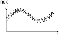
- Fig. 6 Based on Fig. 6 the implemented data reduction is graphically illustrated.
- the data sets are approximated by means of row approaches, whereby each measurement series can be represented as a "smooth approximation" and a high-frequency small disturbance.
- the reduced data R then only contains the smooth approximation.
- step S5 the pump 110 is actuated in particular by means of the drive unit 134.
- the control is based on all measured and calculated pressure and flow values p 1 1 - p 1 n , q 1 1 - q 1 n , p 2 1 - p 2 n , q 2 1 - q 2 n .
- the control unit 134 determines from all pressure values p 1 1 - p 1 n, p 2 1 - p 2 n the minimum pressure and compares it to the desired pressure value p. As long as the minimum pressure determined via the desired pressure value P desired is, it reduces the pressure generated by the pump 110, for example by a corresponding control of the pump 110 driving the electric motor.
- the minimum pressure can be adjusted to the fact that he is in a smallest possible tolerance window around the nominal pressure value p (eg. Pressure value p to +/- 5%) is located.
- one or more valves 138 may be disposed in the utility network 100.
- the valves 138 are configured to control a pressure and / or a flow rate in the tubes 102 of the supply network 100.
- the drive unit 134 may be configured to actuate the valves 138 or actuators thereof analogously to the pump 110. That is, the valves 138 are also controlled such that the determined minimum pressure is within the mentioned tolerance window.
Landscapes
- Engineering & Computer Science (AREA)
- Physics & Mathematics (AREA)
- General Physics & Mathematics (AREA)
- Data Mining & Analysis (AREA)
- Automation & Control Theory (AREA)
- Pure & Applied Mathematics (AREA)
- Life Sciences & Earth Sciences (AREA)
- Theoretical Computer Science (AREA)
- Computational Mathematics (AREA)
- Mathematical Physics (AREA)
- Mathematical Analysis (AREA)
- Mathematical Optimization (AREA)
- Algebra (AREA)
- Hydrology & Water Resources (AREA)
- Operations Research (AREA)
- Evolutionary Biology (AREA)
- Databases & Information Systems (AREA)
- Software Systems (AREA)
- General Engineering & Computer Science (AREA)
- Bioinformatics & Computational Biology (AREA)
- Health & Medical Sciences (AREA)
- Probability & Statistics with Applications (AREA)
- Public Health (AREA)
- Water Supply & Treatment (AREA)
- Bioinformatics & Cheminformatics (AREA)
- Pipeline Systems (AREA)
- Management, Administration, Business Operations System, And Electronic Commerce (AREA)
- Control Of Fluid Pressure (AREA)
- Massaging Devices (AREA)
Claims (14)
- Procédé de régulation de pression dans un réseau d'approvisionnement (100) destiné à un approvisionnement de consommateurs (112) avec un fluide (106), dans lequel le réseau d'approvisionnement (100) présente au moins une pompe (110) destinée au pompage du fluide et/ou au moins une vanne (138) destinée à la commande d'un flux de fluide, comprenant les étapes consistant à :a) définir (S1) au moins un profil de consommation (400) pour le consommateur (112) respectif,b) définir (S2) des données (D) décrivant des profils de pression et/ou de débit (500, 502) au sein du réseau d'approvisionnement (100) en se basant sur les profils de consommation (400),c) réduire (S3) les données (D) pour obtenir des données réduites (R),d) enregistrer (S4) au moins une première valeur de pression et/ou de débit (p1 1 à p1 n, q1 1 à q1 n) au niveau d'au moins un premier emplacement au sein du réseau d'approvisionnement (100),e) reconstruire (S5) au moins une deuxième valeur de pression et/ou de débit (p2 1 à p2 n, q2 1 à q2 n) au niveau d'au moins un deuxième emplacement au sein du réseau d'approvisionnement (100) à partir des données réduites (R) au moyen de la au moins une première valeur de pression et/ou de débit (p1 1 à p1 n, q1 1 à q1 n) , etf) commander (S6) la au moins une pompe (110) et/ou la au moins une vanne (138) en se basant sur la au moins une première valeur de pression et/ou de débit (p1 1 à p1 n, q1 1 à q1 n) et sur la au moins une deuxième valeur de pression et/ou de débit (p2 1 à p2 n, q2 1 à q2 n) .
- Procédé selon la revendication 1,
caractérisé en ce que
à l'étape c), les données (D) sont réduites en se basant sur un développement en série. - Procédé selon la revendication 2,
caractérisé en ce que,
les données (D) sont réduites en se basant sur une analyse en composantes principales, également appelée approche POD resp. méthode de décomposition orthogonale aux valeurs propres. - Procédé selon l'une quelconque des revendications 1 à 3,
caractérisé en ce que,
l'étape e) comprend la reconstruction de la au moins une deuxième valeur de pression et/ou de débit (p2 1 à p2 n, q2 1 à q2 n) à l'aide d'une approche Gappy-POD. - Procédé selon la revendication 4,
caractérisé en ce que,
des deuxièmes valeurs de pression ou de débit (p2 1 à p2 n, q2 1 à q2 n) sont générées pour des points temporels différents en se basant sur la même mise en équation en série (M). - Procédé selon l'une quelconque des revendications 1 à 5,
caractérisé en ce que,
l'étape a) présente les étapes ci-dessous consistant à :- définir (S1-1) une consommation totale de tous les consommateurs (112),- définir (S1-2) une part d'un consommateur (112) respectif dans la consommation totale,- affecter (S1-3) une valeur de consommation de zéro au consommateur (112) respectif,- déterminer (S1-4) une quantité (Q) du fluide (106), qui est inférieure à la consommation totale,- choisir (S1-5) un consommateur (112), dans lequel une probabilité qu'un consommateur soit choisi correspond à sa part dans la consommation totale,- augmenter (S1-6) la valeur de consommation du consommateur (112) choisi à concurrence de la quantité (Q), et- répéter (S1-7) les étapes du choix (S1-5) d'un consommateur (112) et de l'augmentation (S1-6) de la valeur de consommation aussi longtemps que la somme des valeurs de consommation de tous les consommateurs (112) est inférieure à la consommation totale. - Procédé selon la revendication 6,
caractérisé en ce que,
l'étape b) comprend une définition des données (D) décrivant les profils de pression et/ou de débit (500, 502), pendant qu'un consommateur (112) respectif consomme la quantité (Q) du fluide. - Procédé selon la revendication 7,
caractérisé en ce que,
le calcul des données décrivant des profils de pression et/ou de débit (500, 502) a lieu selon la méthode de Monte Carlo. - Procédé selon l'une quelconque des revendications 1 à 8,
caractérisé en ce que,
la au moins une première valeur de pression et/ou de débit (p1 1 à p1 n, q1 1 à q1 n) est enregistrée au niveau du au moins un premier emplacement au sein du réseau d'approvisionnement (100) au moyen d'au moins un premier capteur (116, 118), dans lequel le au moins un premier emplacement est choisi en se basant sur l'approche POD, en particulier l'approche Gappy-POD. - Procédé selon l'une quelconque des revendications 1 à 9,
caractérisé en ce que,
une pression minimale est déterminée à partir de la au moins une première valeur de pression (p1 1 à p1 n) et de la au moins une deuxième valeur de pression (p2 1 à p2 n) et la au moins une pompe (110) et/ou la au moins une vanne (138) est/sont en outre commandée(s) en fonction d'une différence entre une valeur de pression de consigne (Psoll) et la pression minimale déterminée. - Procédé selon l'une quelconque des revendications 1 à 10,
caractérisé en ce que,
à l'étape b), les données (D) décrivent des profils de pression et/ou de débit (500, 502) au sein de noeuds (104) et/ou de conduites (102) du réseau d'approvisionnement (100). - Procédé selon l'une quelconque des revendications 1 à 11,
caractérisé en ce que,
le réseau d'approvisionnement (100) est un réseau d'approvisionnement en eau. - Dispositif (114) de réglage de pression dans un réseau d'approvisionnement (100) destiné à un approvisionnement de consommateurs (112) avec un fluide (106), dans lequel le réseau d'approvisionnement (100) présente au moins une pompe (110) destinée au pompage du fluide (106) et/ou au moins une vanne (138) destinée à la commande d'un flux de fluide, avec :- une unité de définition (120) destinée à définir au moins un profil de consommation (400) pour un consommateur (112) respectif,- une unité de définition (124) destinée à définir des données (D) décrivant des profils de pression et/ou de débit (500, 502) au sein du réseau d'approvisionnement (100) en se basant sur les profils de consommation (400) définis,- une unité de réduction (128) destinée à réduire les données (D) afin d'obtenir des données réduites (R),- une unité d'enregistrement (130) destinée à enregistrer au moins une première valeur de pression et/ou de débit (p1 1 à p1 n, q1 1 à q1 n) au niveau d'au moins un premier emplacement au sein du réseau d'approvisionnement (100),- une unité de reconstruction (132) destinée à reconstruire au moins une deuxième valeur de pression et/ou de débit (p2 1 à p2 n, q2 1 à q2 n) au niveau d'au moins un deuxième emplacement au sein du réseau d'approvisionnement (100) à partir des données réduites (R) au moyen de la au moins une première valeur de pression et/ou de débit (p1 1 à p1 n, q1 1 à q1 n), et- une unité de commande (134) destinée à commander la au moins une pompe (110) et/ou la au moins une vanne (138) en se basant sur la au moins une première valeur de pression et/ou de débit (p1 1 à p1 n, q1 1 à q1 n) et sur la au moins une deuxième valeur de pression et/ou de débit (p2 1 à p2 n, q2 1 à q2 n) .
- Réseau d'approvisionnement (100) destiné à approvisionner des consommateurs (112) avec un fluide (106), comprenant :- des noeuds (104) et/ou des conduites (102),- au moins une pompe (110) destinée au pompage du fluide (106) à travers les noeuds (104) et/ou les conduites (102) et/ou au moins une vanne (138) destinée à commander un flux de fluide à travers les noeuds (104) et/ou les conduites (102), et- au moins un dispositif (114) selon la revendication 13, qui commande la au moins une pompe (110) et/ou la au moins une vanne (138).
Applications Claiming Priority (2)
| Application Number | Priority Date | Filing Date | Title |
|---|---|---|---|
| DE102014205332.3A DE102014205332A1 (de) | 2014-03-21 | 2014-03-21 | Verfahren zur Druckregelung in einem Versorgungsnetz, Vorrichtung sowie Versorgungsnetz |
| PCT/EP2015/050668 WO2015139853A1 (fr) | 2014-03-21 | 2015-01-15 | Procédé pour la régulation de la pression dans un réseau d'alimentation, dispositif et réseau d'alimentation |
Publications (2)
| Publication Number | Publication Date |
|---|---|
| EP3120201A1 EP3120201A1 (fr) | 2017-01-25 |
| EP3120201B1 true EP3120201B1 (fr) | 2017-11-29 |
Family
ID=52391937
Family Applications (1)
| Application Number | Title | Priority Date | Filing Date |
|---|---|---|---|
| EP15700671.9A Not-in-force EP3120201B1 (fr) | 2014-03-21 | 2015-01-15 | Procédé et dispositif de régulation de la pression dans un réseau de distribution d'un fluide |
Country Status (5)
| Country | Link |
|---|---|
| US (1) | US10443217B2 (fr) |
| EP (1) | EP3120201B1 (fr) |
| CN (1) | CN106462129B (fr) |
| DE (1) | DE102014205332A1 (fr) |
| WO (1) | WO2015139853A1 (fr) |
Families Citing this family (12)
| Publication number | Priority date | Publication date | Assignee | Title |
|---|---|---|---|---|
| GB2545899B (en) * | 2015-12-21 | 2018-07-25 | Imperial Innovations Ltd | Management of liquid conduit systems |
| CN108700487B (zh) * | 2016-06-20 | 2021-04-27 | 西门子股份公司 | 针对流体供应网络的离散区域的用于流体流量测量的方法 |
| EP3422122B1 (fr) * | 2017-06-29 | 2022-09-28 | Grundfos Holding A/S | Module de formation de modèles pour créer un modèle de commande du système de régulation de pression d'un réseau d'alimentation en eau |
| DE102017116079A1 (de) * | 2017-07-18 | 2019-01-24 | Eisenmann Se | Versorgungskreis für ein Wärmeträgermedium für einen Verbraucher, Industrieanlage und Verfahren zum Betreiben von solchen |
| SE543008C2 (sv) | 2018-11-22 | 2020-09-22 | Stockholm Exergi Ab | Förfarande och system för balansering av massflöde under produktionsstörning eller -brist i ett fjärrvärmenät |
| EP3699498A1 (fr) * | 2019-02-21 | 2020-08-26 | E.ON Sverige AB | Procédé et appareil permettant de déterminer une déviation dans un circuit d'énergie thermique |
| EP3699569A1 (fr) * | 2019-02-25 | 2020-08-26 | Siemens Aktiengesellschaft | Détection d'une fuite dans un réseau d'alimentation |
| EP3699700A1 (fr) | 2019-02-25 | 2020-08-26 | Siemens Aktiengesellschaft | Régulation de pression dans un un réseau d'alimentation électrique |
| CN110158700B (zh) * | 2019-05-22 | 2020-12-29 | 中国铁路设计集团有限公司 | 一种优质饮用水工程和二次供水改造工程结合的改造方法 |
| EP4013519A4 (fr) | 2019-08-14 | 2024-01-10 | Akron Brass Company | Système de commande de lutte contre l'incendie |
| DE102019213530A1 (de) * | 2019-09-05 | 2021-03-11 | Robert Bosch Gmbh | Verfahren und Vorrichtung zum Betreiben eines Wasserverteilungssystems |
| KR102048243B1 (ko) * | 2019-09-09 | 2019-11-25 | 주식회사 페이스 | 연관-pod를 통하여 현장 측정 데이터와 cae 해석을 결합한 차수 감축 모델 구축 방법 |
Family Cites Families (18)
| Publication number | Priority date | Publication date | Assignee | Title |
|---|---|---|---|---|
| DE2422561C2 (de) | 1974-05-09 | 1983-11-03 | Hoechst Ag, 6230 Frankfurt | Vorrichtung zur Lecküberwachung einer Rohrleitung |
| GB9212122D0 (en) * | 1992-06-09 | 1992-07-22 | Technolog Ltd | Water supply pressure control apparatus |
| US6789620B2 (en) * | 2001-02-16 | 2004-09-14 | Halliburton Energy Services, Inc. | Downhole sensing and flow control utilizing neural networks |
| AUPR353801A0 (en) * | 2001-03-02 | 2001-03-29 | Rubicon Systems Australia Pty Ltd | Fluid regulation |
| US6648077B2 (en) * | 2001-07-12 | 2003-11-18 | Bryan K. Hoffman | Fire extinguishing system |
| US6786245B1 (en) * | 2003-02-21 | 2004-09-07 | Air Products And Chemicals, Inc. | Self-contained mobile fueling station |
| EP1694990A4 (fr) * | 2003-11-24 | 2009-12-09 | Microstaq Inc | Dispositif de micro-vanne permettant de controler un compresseur a deplacement variable |
| US7539570B2 (en) * | 2004-06-22 | 2009-05-26 | Caterpillar S.A.R.L. | Machine operating system and method |
| US7658598B2 (en) * | 2005-10-24 | 2010-02-09 | Proportionair, Incorporated | Method and control system for a pump |
| US20080295568A1 (en) * | 2007-06-01 | 2008-12-04 | Gilbarco Inc. | System and method for automated calibration of a fuel flow meter in a fuel dispenser |
| JP4564594B2 (ja) * | 2008-04-17 | 2010-10-20 | 株式会社E.I.エンジニアリング | 熱電設備のシミュレーションシステム |
| GB0811942D0 (en) * | 2008-07-01 | 2008-07-30 | Airbus Uk Ltd | Method of designing a structure |
| DE102008064491A1 (de) * | 2008-12-23 | 2010-06-24 | Kaeser Kompressoren Gmbh | Simulationsgestütztes Verfahren zur Steuerung bzw. Regelung von Druckluftstationen |
| US8457908B2 (en) * | 2009-06-11 | 2013-06-04 | University Of Washington | Sensing events affecting liquid flow in a liquid distribution system |
| DE102011078240A1 (de) * | 2011-06-28 | 2013-01-03 | Siemens Aktiengesellschaft | Leckageerkennung mittels stochastischer Massenbilanz |
| US20130085619A1 (en) * | 2011-10-04 | 2013-04-04 | Cory Howard | Methods and systems for remote controlling of irrigation systems |
| US20140137744A1 (en) * | 2012-10-12 | 2014-05-22 | Inova Labs, Inc., A Delaware Corporation | Oxygen concentrator systems and methods |
| US10437210B2 (en) * | 2013-10-14 | 2019-10-08 | Aveva Software, Llc | Interactive feedback for variable equation specifications |
-
2014
- 2014-03-21 DE DE102014205332.3A patent/DE102014205332A1/de not_active Withdrawn
-
2015
- 2015-01-15 CN CN201580015449.8A patent/CN106462129B/zh not_active Expired - Fee Related
- 2015-01-15 US US15/117,317 patent/US10443217B2/en active Active
- 2015-01-15 WO PCT/EP2015/050668 patent/WO2015139853A1/fr not_active Ceased
- 2015-01-15 EP EP15700671.9A patent/EP3120201B1/fr not_active Not-in-force
Also Published As
| Publication number | Publication date |
|---|---|
| EP3120201A1 (fr) | 2017-01-25 |
| US10443217B2 (en) | 2019-10-15 |
| WO2015139853A1 (fr) | 2015-09-24 |
| DE102014205332A1 (de) | 2015-09-24 |
| CN106462129B (zh) | 2019-02-19 |
| US20170037604A1 (en) | 2017-02-09 |
| CN106462129A (zh) | 2017-02-22 |
Similar Documents
| Publication | Publication Date | Title |
|---|---|---|
| DE102014205332A1 (de) | Verfahren zur Druckregelung in einem Versorgungsnetz, Vorrichtung sowie Versorgungsnetz | |
| EP3877816B1 (fr) | Régulation de pression dans un un réseau d'alimentation électrique | |
| EP2936003B1 (fr) | Procédé et dispositifs d'équilibrage d'un groupe de récepteurs dans un système de transport de fluides | |
| DE102018212140A1 (de) | Anlagensteuervorrichtung und Steuerverfahren dafür, Walzwerksteuervorrichtung und Steuerverfahren und Programm dafür | |
| DE102014223810A1 (de) | Verfahren und Assistenzsystem zur Erkennung einer Störung in einer Anlage | |
| WO2009071484A2 (fr) | Procédé de fonctionnement d'un système de conduites de transport de fluide | |
| DE102014016791B4 (de) | Verfahren zur hydraulischen Regelung mehrerer Heizkreisläufe am Verteilerbalken | |
| EP2057420B1 (fr) | Procédé pour exécuter une analyse de réseau de tuyauterie dans un réseau de tuyauterie | |
| EP3647899A1 (fr) | Procédé de fonctionnement d'une soupape, unité de commande électronique associée et entraînement de soupape | |
| EP3425291A1 (fr) | Procédé d'attribution d'une sonde de température à circuit de chauffage d'un système de chauffage et / ou de refroidissement à un circuit de chauffage ou de vérification de l'attribution d'une sonde de température à circuit de chauffage d'un système de chauffage et / ou de refroidissement à un circuit de chauffage | |
| DE102014001413A1 (de) | Verfahren zur Bestimmung der Systemkennlinie eines Verteilernetzes | |
| EP3599583A1 (fr) | Détermination de la consommation de l'énergie de chauffage ou de refroidissement d'une sous-unité de construction | |
| EP1462901A2 (fr) | Procédé et dispositif pour la régulation ou la commande d'un processus de variation de charge thermique dans une piece non déformable et/ou à paroi épaisse traversée par un fluide dans une installation thermique | |
| EP3168540A1 (fr) | Procédé d'exécution d'un équilibrage hydraulique automatisé, soupape et installation de chauffage associées | |
| DE102006041345A1 (de) | Verfahren zum Betrieb eines Rohrnetzes | |
| DE102017126341A1 (de) | Verfahren und Vorrichtung zur Bestimmung eines Verschleißzustands in einer Hydrostatpumpe | |
| DE102012002028B4 (de) | Verfahren zur optimalen Auslegung und Steuerung einer Erdwärmeanlage | |
| DE102020210978A1 (de) | Kühlverfahren für ein hydraulisches Element eines Kühlölkreislaufs, Steuergerät, Kraftfahrzeug | |
| WO2017050659A1 (fr) | Procédé et dispositif de fonctionnement d'un système technique | |
| EP3320216B1 (fr) | Dispositif de simulation et procédé de simulation | |
| EP4040053A1 (fr) | Dispositif et procédé de détermination d'une valeur de consommation thermique d'un consommateur thermique d'une installation | |
| DE102016008016A1 (de) | Verfahren und System zur Regelung einer Pumpstation | |
| WO2010094487A1 (fr) | Procédé et dispositif de surveillance d'une installation de pasteurisation | |
| EP1906273A1 (fr) | Procédé destiné au fonctionnement d'une installation à l'échelon industriel tout comme système de gestion d'une installation à l'échelon industriel | |
| DE102020210976B4 (de) | Steuerverfahren, Kühlölkreislauf, Steuergerät, Kraftfahrzeug |
Legal Events
| Date | Code | Title | Description |
|---|---|---|---|
| PUAI | Public reference made under article 153(3) epc to a published international application that has entered the european phase |
Free format text: ORIGINAL CODE: 0009012 |
|
| 17P | Request for examination filed |
Effective date: 20160523 |
|
| AK | Designated contracting states |
Kind code of ref document: A1 Designated state(s): AL AT BE BG CH CY CZ DE DK EE ES FI FR GB GR HR HU IE IS IT LI LT LU LV MC MK MT NL NO PL PT RO RS SE SI SK SM TR |
|
| AX | Request for extension of the european patent |
Extension state: BA ME |
|
| GRAP | Despatch of communication of intention to grant a patent |
Free format text: ORIGINAL CODE: EPIDOSNIGR1 |
|
| DAX | Request for extension of the european patent (deleted) | ||
| INTG | Intention to grant announced |
Effective date: 20170523 |
|
| RAP1 | Party data changed (applicant data changed or rights of an application transferred) |
Owner name: SIEMENS AKTIENGESELLSCHAFT |
|
| GRAS | Grant fee paid |
Free format text: ORIGINAL CODE: EPIDOSNIGR3 |
|
| GRAA | (expected) grant |
Free format text: ORIGINAL CODE: 0009210 |
|
| AK | Designated contracting states |
Kind code of ref document: B1 Designated state(s): AL AT BE BG CH CY CZ DE DK EE ES FI FR GB GR HR HU IE IS IT LI LT LU LV MC MK MT NL NO PL PT RO RS SE SI SK SM TR |
|
| REG | Reference to a national code |
Ref country code: CH Ref legal event code: EP |
|
| REG | Reference to a national code |
Ref country code: AT Ref legal event code: REF Ref document number: 950945 Country of ref document: AT Kind code of ref document: T Effective date: 20171215 |
|
| REG | Reference to a national code |
Ref country code: IE Ref legal event code: FG4D Free format text: LANGUAGE OF EP DOCUMENT: GERMAN |
|
| REG | Reference to a national code |
Ref country code: DE Ref legal event code: R096 Ref document number: 502015002449 Country of ref document: DE |
|
| REG | Reference to a national code |
Ref country code: FR Ref legal event code: PLFP Year of fee payment: 4 |
|
| REG | Reference to a national code |
Ref country code: NL Ref legal event code: MP Effective date: 20171129 |
|
| REG | Reference to a national code |
Ref country code: LT Ref legal event code: MG4D |
|
| PG25 | Lapsed in a contracting state [announced via postgrant information from national office to epo] |
Ref country code: FI Free format text: LAPSE BECAUSE OF FAILURE TO SUBMIT A TRANSLATION OF THE DESCRIPTION OR TO PAY THE FEE WITHIN THE PRESCRIBED TIME-LIMIT Effective date: 20171129 Ref country code: LT Free format text: LAPSE BECAUSE OF FAILURE TO SUBMIT A TRANSLATION OF THE DESCRIPTION OR TO PAY THE FEE WITHIN THE PRESCRIBED TIME-LIMIT Effective date: 20171129 Ref country code: SE Free format text: LAPSE BECAUSE OF FAILURE TO SUBMIT A TRANSLATION OF THE DESCRIPTION OR TO PAY THE FEE WITHIN THE PRESCRIBED TIME-LIMIT Effective date: 20171129 Ref country code: NO Free format text: LAPSE BECAUSE OF FAILURE TO SUBMIT A TRANSLATION OF THE DESCRIPTION OR TO PAY THE FEE WITHIN THE PRESCRIBED TIME-LIMIT Effective date: 20180228 Ref country code: ES Free format text: LAPSE BECAUSE OF FAILURE TO SUBMIT A TRANSLATION OF THE DESCRIPTION OR TO PAY THE FEE WITHIN THE PRESCRIBED TIME-LIMIT Effective date: 20171129 |
|
| PG25 | Lapsed in a contracting state [announced via postgrant information from national office to epo] |
Ref country code: BG Free format text: LAPSE BECAUSE OF FAILURE TO SUBMIT A TRANSLATION OF THE DESCRIPTION OR TO PAY THE FEE WITHIN THE PRESCRIBED TIME-LIMIT Effective date: 20180228 Ref country code: HR Free format text: LAPSE BECAUSE OF FAILURE TO SUBMIT A TRANSLATION OF THE DESCRIPTION OR TO PAY THE FEE WITHIN THE PRESCRIBED TIME-LIMIT Effective date: 20171129 Ref country code: GR Free format text: LAPSE BECAUSE OF FAILURE TO SUBMIT A TRANSLATION OF THE DESCRIPTION OR TO PAY THE FEE WITHIN THE PRESCRIBED TIME-LIMIT Effective date: 20180301 Ref country code: RS Free format text: LAPSE BECAUSE OF FAILURE TO SUBMIT A TRANSLATION OF THE DESCRIPTION OR TO PAY THE FEE WITHIN THE PRESCRIBED TIME-LIMIT Effective date: 20171129 Ref country code: LV Free format text: LAPSE BECAUSE OF FAILURE TO SUBMIT A TRANSLATION OF THE DESCRIPTION OR TO PAY THE FEE WITHIN THE PRESCRIBED TIME-LIMIT Effective date: 20171129 |
|
| PG25 | Lapsed in a contracting state [announced via postgrant information from national office to epo] |
Ref country code: NL Free format text: LAPSE BECAUSE OF FAILURE TO SUBMIT A TRANSLATION OF THE DESCRIPTION OR TO PAY THE FEE WITHIN THE PRESCRIBED TIME-LIMIT Effective date: 20171129 |
|
| PG25 | Lapsed in a contracting state [announced via postgrant information from national office to epo] |
Ref country code: CZ Free format text: LAPSE BECAUSE OF FAILURE TO SUBMIT A TRANSLATION OF THE DESCRIPTION OR TO PAY THE FEE WITHIN THE PRESCRIBED TIME-LIMIT Effective date: 20171129 Ref country code: DK Free format text: LAPSE BECAUSE OF FAILURE TO SUBMIT A TRANSLATION OF THE DESCRIPTION OR TO PAY THE FEE WITHIN THE PRESCRIBED TIME-LIMIT Effective date: 20171129 Ref country code: EE Free format text: LAPSE BECAUSE OF FAILURE TO SUBMIT A TRANSLATION OF THE DESCRIPTION OR TO PAY THE FEE WITHIN THE PRESCRIBED TIME-LIMIT Effective date: 20171129 Ref country code: CY Free format text: LAPSE BECAUSE OF FAILURE TO SUBMIT A TRANSLATION OF THE DESCRIPTION OR TO PAY THE FEE WITHIN THE PRESCRIBED TIME-LIMIT Effective date: 20171129 Ref country code: SK Free format text: LAPSE BECAUSE OF FAILURE TO SUBMIT A TRANSLATION OF THE DESCRIPTION OR TO PAY THE FEE WITHIN THE PRESCRIBED TIME-LIMIT Effective date: 20171129 |
|
| REG | Reference to a national code |
Ref country code: DE Ref legal event code: R097 Ref document number: 502015002449 Country of ref document: DE |
|
| PG25 | Lapsed in a contracting state [announced via postgrant information from national office to epo] |
Ref country code: RO Free format text: LAPSE BECAUSE OF FAILURE TO SUBMIT A TRANSLATION OF THE DESCRIPTION OR TO PAY THE FEE WITHIN THE PRESCRIBED TIME-LIMIT Effective date: 20171129 Ref country code: SM Free format text: LAPSE BECAUSE OF FAILURE TO SUBMIT A TRANSLATION OF THE DESCRIPTION OR TO PAY THE FEE WITHIN THE PRESCRIBED TIME-LIMIT Effective date: 20171129 Ref country code: PL Free format text: LAPSE BECAUSE OF FAILURE TO SUBMIT A TRANSLATION OF THE DESCRIPTION OR TO PAY THE FEE WITHIN THE PRESCRIBED TIME-LIMIT Effective date: 20171129 |
|
| REG | Reference to a national code |
Ref country code: CH Ref legal event code: PL |
|
| PG25 | Lapsed in a contracting state [announced via postgrant information from national office to epo] |
Ref country code: MT Free format text: LAPSE BECAUSE OF FAILURE TO SUBMIT A TRANSLATION OF THE DESCRIPTION OR TO PAY THE FEE WITHIN THE PRESCRIBED TIME-LIMIT Effective date: 20171129 |
|
| PLBE | No opposition filed within time limit |
Free format text: ORIGINAL CODE: 0009261 |
|
| STAA | Information on the status of an ep patent application or granted ep patent |
Free format text: STATUS: NO OPPOSITION FILED WITHIN TIME LIMIT |
|
| PG25 | Lapsed in a contracting state [announced via postgrant information from national office to epo] |
Ref country code: LU Free format text: LAPSE BECAUSE OF NON-PAYMENT OF DUE FEES Effective date: 20180115 |
|
| REG | Reference to a national code |
Ref country code: IE Ref legal event code: MM4A |
|
| 26N | No opposition filed |
Effective date: 20180830 |
|
| REG | Reference to a national code |
Ref country code: BE Ref legal event code: MM Effective date: 20180131 |
|
| PG25 | Lapsed in a contracting state [announced via postgrant information from national office to epo] |
Ref country code: CH Free format text: LAPSE BECAUSE OF NON-PAYMENT OF DUE FEES Effective date: 20180131 Ref country code: LI Free format text: LAPSE BECAUSE OF NON-PAYMENT OF DUE FEES Effective date: 20180131 Ref country code: BE Free format text: LAPSE BECAUSE OF NON-PAYMENT OF DUE FEES Effective date: 20180131 |
|
| PG25 | Lapsed in a contracting state [announced via postgrant information from national office to epo] |
Ref country code: IE Free format text: LAPSE BECAUSE OF NON-PAYMENT OF DUE FEES Effective date: 20180115 |
|
| PG25 | Lapsed in a contracting state [announced via postgrant information from national office to epo] |
Ref country code: MC Free format text: LAPSE BECAUSE OF FAILURE TO SUBMIT A TRANSLATION OF THE DESCRIPTION OR TO PAY THE FEE WITHIN THE PRESCRIBED TIME-LIMIT Effective date: 20171129 |
|
| PG25 | Lapsed in a contracting state [announced via postgrant information from national office to epo] |
Ref country code: TR Free format text: LAPSE BECAUSE OF FAILURE TO SUBMIT A TRANSLATION OF THE DESCRIPTION OR TO PAY THE FEE WITHIN THE PRESCRIBED TIME-LIMIT Effective date: 20171129 |
|
| PG25 | Lapsed in a contracting state [announced via postgrant information from national office to epo] |
Ref country code: PT Free format text: LAPSE BECAUSE OF FAILURE TO SUBMIT A TRANSLATION OF THE DESCRIPTION OR TO PAY THE FEE WITHIN THE PRESCRIBED TIME-LIMIT Effective date: 20171129 |
|
| PG25 | Lapsed in a contracting state [announced via postgrant information from national office to epo] |
Ref country code: MK Free format text: LAPSE BECAUSE OF NON-PAYMENT OF DUE FEES Effective date: 20171129 Ref country code: HU Free format text: LAPSE BECAUSE OF FAILURE TO SUBMIT A TRANSLATION OF THE DESCRIPTION OR TO PAY THE FEE WITHIN THE PRESCRIBED TIME-LIMIT; INVALID AB INITIO Effective date: 20150115 |
|
| PG25 | Lapsed in a contracting state [announced via postgrant information from national office to epo] |
Ref country code: AL Free format text: LAPSE BECAUSE OF FAILURE TO SUBMIT A TRANSLATION OF THE DESCRIPTION OR TO PAY THE FEE WITHIN THE PRESCRIBED TIME-LIMIT Effective date: 20171129 Ref country code: IS Free format text: LAPSE BECAUSE OF FAILURE TO SUBMIT A TRANSLATION OF THE DESCRIPTION OR TO PAY THE FEE WITHIN THE PRESCRIBED TIME-LIMIT Effective date: 20180329 |
|
| PG25 | Lapsed in a contracting state [announced via postgrant information from national office to epo] |
Ref country code: SI Free format text: LAPSE BECAUSE OF NON-PAYMENT OF DUE FEES Effective date: 20180115 |
|
| REG | Reference to a national code |
Ref country code: AT Ref legal event code: MM01 Ref document number: 950945 Country of ref document: AT Kind code of ref document: T Effective date: 20200115 |
|
| PG25 | Lapsed in a contracting state [announced via postgrant information from national office to epo] |
Ref country code: AT Free format text: LAPSE BECAUSE OF NON-PAYMENT OF DUE FEES Effective date: 20200115 |
|
| PGFP | Annual fee paid to national office [announced via postgrant information from national office to epo] |
Ref country code: DE Payment date: 20240318 Year of fee payment: 10 Ref country code: GB Payment date: 20240212 Year of fee payment: 10 |
|
| PGFP | Annual fee paid to national office [announced via postgrant information from national office to epo] |
Ref country code: IT Payment date: 20240124 Year of fee payment: 10 Ref country code: FR Payment date: 20240116 Year of fee payment: 10 |
|
| REG | Reference to a national code |
Ref country code: DE Ref legal event code: R119 Ref document number: 502015002449 Country of ref document: DE |
|
| GBPC | Gb: european patent ceased through non-payment of renewal fee |
Effective date: 20250115 |
|
| PG25 | Lapsed in a contracting state [announced via postgrant information from national office to epo] |
Ref country code: DE Free format text: LAPSE BECAUSE OF NON-PAYMENT OF DUE FEES Effective date: 20250801 |
|
| PG25 | Lapsed in a contracting state [announced via postgrant information from national office to epo] |
Ref country code: GB Free format text: LAPSE BECAUSE OF NON-PAYMENT OF DUE FEES Effective date: 20250115 |
|
| PG25 | Lapsed in a contracting state [announced via postgrant information from national office to epo] |
Ref country code: FR Free format text: LAPSE BECAUSE OF NON-PAYMENT OF DUE FEES Effective date: 20250131 |
|
| PG25 | Lapsed in a contracting state [announced via postgrant information from national office to epo] |
Ref country code: IT Free format text: LAPSE BECAUSE OF NON-PAYMENT OF DUE FEES Effective date: 20250115 |