EP3699700A1 - Régulation de pression dans un un réseau d'alimentation électrique - Google Patents
Régulation de pression dans un un réseau d'alimentation électrique Download PDFInfo
- Publication number
- EP3699700A1 EP3699700A1 EP19159109.8A EP19159109A EP3699700A1 EP 3699700 A1 EP3699700 A1 EP 3699700A1 EP 19159109 A EP19159109 A EP 19159109A EP 3699700 A1 EP3699700 A1 EP 3699700A1
- Authority
- EP
- European Patent Office
- Prior art keywords
- supply network
- pressure
- fluid
- locations
- location
- Prior art date
- Legal status (The legal status is an assumption and is not a legal conclusion. Google has not performed a legal analysis and makes no representation as to the accuracy of the status listed.)
- Withdrawn
Links
Images
Classifications
-
- G—PHYSICS
- G05—CONTROLLING; REGULATING
- G05D—SYSTEMS FOR CONTROLLING OR REGULATING NON-ELECTRIC VARIABLES
- G05D16/00—Control of fluid pressure
- G05D16/20—Control of fluid pressure characterised by the use of electric means
- G05D16/2006—Control of fluid pressure characterised by the use of electric means with direct action of electric energy on controlling means
- G05D16/208—Control of fluid pressure characterised by the use of electric means with direct action of electric energy on controlling means using a combination of controlling means as defined in G05D16/2013 and G05D16/2066
-
- G—PHYSICS
- G05—CONTROLLING; REGULATING
- G05B—CONTROL OR REGULATING SYSTEMS IN GENERAL; FUNCTIONAL ELEMENTS OF SUCH SYSTEMS; MONITORING OR TESTING ARRANGEMENTS FOR SUCH SYSTEMS OR ELEMENTS
- G05B19/00—Program-control systems
- G05B19/02—Program-control systems electric
- G05B19/04—Program control other than numerical control, i.e. in sequence controllers or logic controllers
- G05B19/042—Program control other than numerical control, i.e. in sequence controllers or logic controllers using digital processors
- G05B19/0426—Programming the control sequence
-
- E—FIXED CONSTRUCTIONS
- E03—WATER SUPPLY; SEWERAGE
- E03B—INSTALLATIONS OR METHODS FOR OBTAINING, COLLECTING, OR DISTRIBUTING WATER
- E03B1/00—Methods or layout of installations for water supply
- E03B1/02—Methods or layout of installations for water supply for public or like main supply for industrial use
-
- E—FIXED CONSTRUCTIONS
- E03—WATER SUPPLY; SEWERAGE
- E03B—INSTALLATIONS OR METHODS FOR OBTAINING, COLLECTING, OR DISTRIBUTING WATER
- E03B7/00—Water main or service pipe systems
- E03B7/07—Arrangement of devices, e.g. filters, flow controls, measuring devices, siphons or valves, in the pipe systems
- E03B7/075—Arrangement of devices for control of pressure or flow rate
-
- F—MECHANICAL ENGINEERING; LIGHTING; HEATING; WEAPONS; BLASTING
- F17—STORING OR DISTRIBUTING GASES OR LIQUIDS
- F17D—PIPE-LINE SYSTEMS; PIPE-LINES
- F17D3/00—Arrangements for supervising or controlling working operations
- F17D3/01—Arrangements for supervising or controlling working operations for controlling, signalling, or supervising the conveyance of a product
-
- F—MECHANICAL ENGINEERING; LIGHTING; HEATING; WEAPONS; BLASTING
- F17—STORING OR DISTRIBUTING GASES OR LIQUIDS
- F17D—PIPE-LINE SYSTEMS; PIPE-LINES
- F17D5/00—Protection or supervision of installations
- F17D5/02—Preventing, monitoring, or locating loss
- F17D5/06—Preventing, monitoring, or locating loss using electric or acoustic means
-
- G—PHYSICS
- G06—COMPUTING OR CALCULATING; COUNTING
- G06N—COMPUTING ARRANGEMENTS BASED ON SPECIFIC COMPUTATIONAL MODELS
- G06N3/00—Computing arrangements based on biological models
- G06N3/02—Neural networks
-
- G—PHYSICS
- G06—COMPUTING OR CALCULATING; COUNTING
- G06N—COMPUTING ARRANGEMENTS BASED ON SPECIFIC COMPUTATIONAL MODELS
- G06N3/00—Computing arrangements based on biological models
- G06N3/02—Neural networks
- G06N3/04—Architecture, e.g. interconnection topology
- G06N3/0499—Feedforward networks
-
- G—PHYSICS
- G06—COMPUTING OR CALCULATING; COUNTING
- G06N—COMPUTING ARRANGEMENTS BASED ON SPECIFIC COMPUTATIONAL MODELS
- G06N3/00—Computing arrangements based on biological models
- G06N3/02—Neural networks
- G06N3/08—Learning methods
-
- G—PHYSICS
- G06—COMPUTING OR CALCULATING; COUNTING
- G06N—COMPUTING ARRANGEMENTS BASED ON SPECIFIC COMPUTATIONAL MODELS
- G06N3/00—Computing arrangements based on biological models
- G06N3/02—Neural networks
- G06N3/08—Learning methods
- G06N3/09—Supervised learning
-
- G—PHYSICS
- G06—COMPUTING OR CALCULATING; COUNTING
- G06Q—INFORMATION AND COMMUNICATION TECHNOLOGY [ICT] SPECIALLY ADAPTED FOR ADMINISTRATIVE, COMMERCIAL, FINANCIAL, MANAGERIAL OR SUPERVISORY PURPOSES; SYSTEMS OR METHODS SPECIALLY ADAPTED FOR ADMINISTRATIVE, COMMERCIAL, FINANCIAL, MANAGERIAL OR SUPERVISORY PURPOSES, NOT OTHERWISE PROVIDED FOR
- G06Q50/00—Information and communication technology [ICT] specially adapted for implementation of business processes of specific business sectors, e.g. utilities or tourism
- G06Q50/06—Energy or water supply
-
- G—PHYSICS
- G05—CONTROLLING; REGULATING
- G05B—CONTROL OR REGULATING SYSTEMS IN GENERAL; FUNCTIONAL ELEMENTS OF SUCH SYSTEMS; MONITORING OR TESTING ARRANGEMENTS FOR SUCH SYSTEMS OR ELEMENTS
- G05B2219/00—Program-control systems
- G05B2219/20—Pc systems
- G05B2219/25—Pc structure of the system
- G05B2219/25255—Neural network
-
- G—PHYSICS
- G05—CONTROLLING; REGULATING
- G05B—CONTROL OR REGULATING SYSTEMS IN GENERAL; FUNCTIONAL ELEMENTS OF SUCH SYSTEMS; MONITORING OR TESTING ARRANGEMENTS FOR SUCH SYSTEMS OR ELEMENTS
- G05B2219/00—Program-control systems
- G05B2219/20—Pc systems
- G05B2219/26—Pc applications
- G05B2219/2625—Sprinkler, irrigation, watering
-
- G—PHYSICS
- G05—CONTROLLING; REGULATING
- G05B—CONTROL OR REGULATING SYSTEMS IN GENERAL; FUNCTIONAL ELEMENTS OF SUCH SYSTEMS; MONITORING OR TESTING ARRANGEMENTS FOR SUCH SYSTEMS OR ELEMENTS
- G05B2219/00—Program-control systems
- G05B2219/20—Pc systems
- G05B2219/26—Pc applications
- G05B2219/2638—Airconditioning
-
- G—PHYSICS
- G05—CONTROLLING; REGULATING
- G05B—CONTROL OR REGULATING SYSTEMS IN GENERAL; FUNCTIONAL ELEMENTS OF SUCH SYSTEMS; MONITORING OR TESTING ARRANGEMENTS FOR SUCH SYSTEMS OR ELEMENTS
- G05B2219/00—Program-control systems
- G05B2219/20—Pc systems
- G05B2219/26—Pc applications
- G05B2219/2642—Domotique, domestic, home control, automation, smart house
-
- G—PHYSICS
- G05—CONTROLLING; REGULATING
- G05B—CONTROL OR REGULATING SYSTEMS IN GENERAL; FUNCTIONAL ELEMENTS OF SUCH SYSTEMS; MONITORING OR TESTING ARRANGEMENTS FOR SUCH SYSTEMS OR ELEMENTS
- G05B2219/00—Program-control systems
- G05B2219/30—Nc systems
- G05B2219/33—Director till display
- G05B2219/33027—Artificial neural network controller
-
- G—PHYSICS
- G05—CONTROLLING; REGULATING
- G05B—CONTROL OR REGULATING SYSTEMS IN GENERAL; FUNCTIONAL ELEMENTS OF SUCH SYSTEMS; MONITORING OR TESTING ARRANGEMENTS FOR SUCH SYSTEMS OR ELEMENTS
- G05B2219/00—Program-control systems
- G05B2219/30—Nc systems
- G05B2219/37—Measurements
- G05B2219/37371—Flow
-
- G—PHYSICS
- G05—CONTROLLING; REGULATING
- G05B—CONTROL OR REGULATING SYSTEMS IN GENERAL; FUNCTIONAL ELEMENTS OF SUCH SYSTEMS; MONITORING OR TESTING ARRANGEMENTS FOR SUCH SYSTEMS OR ELEMENTS
- G05B2219/00—Program-control systems
- G05B2219/30—Nc systems
- G05B2219/41—Servomotor, servo controller till figures
- G05B2219/41054—Using neural network techniques
-
- G—PHYSICS
- G05—CONTROLLING; REGULATING
- G05B—CONTROL OR REGULATING SYSTEMS IN GENERAL; FUNCTIONAL ELEMENTS OF SUCH SYSTEMS; MONITORING OR TESTING ARRANGEMENTS FOR SUCH SYSTEMS OR ELEMENTS
- G05B2219/00—Program-control systems
- G05B2219/30—Nc systems
- G05B2219/45—Nc applications
- G05B2219/45207—Actuator to regulate position, flow, speed, process variable
-
- G—PHYSICS
- G06—COMPUTING OR CALCULATING; COUNTING
- G06N—COMPUTING ARRANGEMENTS BASED ON SPECIFIC COMPUTATIONAL MODELS
- G06N3/00—Computing arrangements based on biological models
- G06N3/02—Neural networks
- G06N3/08—Learning methods
- G06N3/084—Backpropagation, e.g. using gradient descent
Definitions
- the invention relates to a method for regulating pressure in a supply network.
- Exemplary applications are pressure control in a drinking or sewage network or in a gas or district heating supply network.
- the hydraulic pressure prevailing in a water supply network is an important quality feature. For large industrial consumers and fire hydrants, high pressure guarantees that a large amount of water can be drawn from the supply network in a short time. A sufficiently high water pressure at the house connections allows entire buildings to be reliably supplied with drinking water up to the top floor without additional pumping equipment.
- too high a pressure in the supply network leads to premature aging and failure of components, for example due to a broken pipe.
- the resulting leaks lead to high repair costs, water loss and, in some cases, further damage to surrounding structures.
- overpressure leads to increased water loss through background leakage.
- Such background leaks tend to be present to some extent in any water network and result in continual loss of drinking water.
- Too high a flow pressure also increases the friction losses occurring in the pipe flow.
- an increase in the pressure provided leads directly to an increased energy requirement of the pumps.
- pressure management to adapt the pressure prevailing in the water distribution network to the requirements of the consumer and thus avoid excessively high pressures and the associated disadvantages.
- the technologies developed in this context include the subdivision of the supply network into pressure management zones (PMZ), in which the pressure at the inflows is reduced to a minimum through targeted control of valves or pumps.
- PMZ pressure management zones
- To design the pressure control knowledge of the network structure, the topographical conditions of the pressure zone and the number and type of connected consumers are used. To get on by changing To be able to react to dynamic pressure fluctuations caused by consumption, pressure values measured online in the zone are now also used for pressure control.
- the European patent application EP 3 120 201 discloses a method for regulating pressure in a supply network.
- a central component of this process is the creation of a simulation model of the supply network.
- the simulation model simulates pressure and / or flow profiles depending on consumption profiles.
- the data describing the pressure and / or flow profiles are then reduced. All of this can take place "offline", that is to say outside of actual operation, in particular before the supply network is put into operation.
- a first pressure and / or flow value is now measured at at least one first point in the supply network by means of at least one first sensor.
- the reduced data have less data and / or a lower data complexity than the (non-reduced) data.
- the use of the reduced data to determine the second pressure and / or flow values has the advantage that less computing power is required and, accordingly, rapid control of the at least one pump or the at least one valve, in particular in real time, is made possible.
- the creation of such a simulation model is relatively complex, for example in the case of a complex course of the pipelines of the supply network, or there is almost not enough information available regarding the topology of the supply network and the consumers connected to the supply network.
- the reconstruction can of the second pressure or flow value take longer than desired for the control of the pump and / or the valve despite the reduction of the data from the simulation model.
- one object of the present invention is to provide an alternative concept for regulating pressure in a supply network, which in particular enables the pump and / or the valve to be controlled quickly.
- a self-learning system can advantageously be used for pressure regulation in a supply network.
- the self-learning system is taught to be able to predict the pressure at a given location in the supply network.
- the learned system is used during operation of the supply network.
- the learned system predicts the pressure at a specific location in the supply network based on the flow rates and / or pressures actually measured during operation. The idea is that the predicted value correctly indicates the actual pressure. Thanks to the prediction of the learned system, in particular no measurement of the flow rate and / or pressure at the second location is necessary in order to know the pressure at the second location (provided that the prediction of the learned system is correct).
- a first advantage consists in the fact that it is possible to know the pressure at locations in the supply network where no sensor is placed and where no measurement at the said location is necessary for knowing this. As will be described in detail later, it is sometimes advantageous to measure the pressure and / or the flow rate at the corresponding "second" location while the self-learning system is being taught. However, there are alternatives for this, too, if the second location is e.g. is difficult or impossible to access for a direct measurement. In any case, no sensor is required at the second location for pressure control, as the pressure at that location is predicted with the help of the learned system.
- a second advantage of the method according to the invention is that the pressure can be determined quickly at the second location.
- a learned system is characterized, among other things, by the fact that it is used for input data - here the measured flow rates and / or pressures of the first sensors - usually very quickly the required output - here the pressure at the second location - outputs.
- the pressure at the second location is also available quasi “online” and without a time delay after measuring the flow rates and / or pressures at the first locations. This is of relevance for a control method such as the present method for controlling the pressure in a supply network, which should not be underestimated.
- a prediction of the pressure is usually only possible for the location for which the self-learning system was also trained. However, it is possible to train the self-learning system to predict the pressure at several locations in the supply network. The number of measuring points in the network does not necessarily have to be greater than the number of locations whose pressures are predicted, but it is usually.
- a fluid is understood to mean any type of liquid or gas.
- the supply network is in particular a drinking water supply or sewage network.
- the supply network is in particular a gas supply network.
- the transfer medium that is to say the fluid, is mostly hot water, and more rarely steam.
- the supply network includes in particular a number of pipes, which are also referred to as pipelines or just as lines.
- the pipes are there to guide the fluid to the consumers and, if necessary, away from them again.
- the tubes are therefore designed for the fluid to flow through.
- the flow rate at a specific location in the supply network is understood to mean the volume of the fluid that flows through the cross section of the pipe at the corresponding location over a period of time.
- the cross-section of the pipe is determined by its inner diameter.
- the flow is also referred to as "volume flow” or “flow rate”. It has the SI unit m 3 / h.
- the flow rate means a value that characterizes and quantifies the flow rate. It can therefore also be referred to as the "flow rate”.
- a flow meter usually has two main components: the actual measuring sensor, which serves as a flow sensor, and an evaluation and supply part, which is also referred to as a transmitter or measuring transducer.
- the flow meters are also referred to as “sensors” in the context of this patent application.
- the pressure at a specific location in the supply network is understood to be the hydrodynamic pressure of the liquid at this location.
- the hydrodynamic pressure cannot be measured directly, but with loss-free, horizontal and steady flow, it can be determined by measuring the difference between total pressure and static pressure, for example with a Prandtl probe, which is a combination of a pitot tube and a static pressure probe.
- a Prandtl probe which is a combination of a pitot tube and a static pressure probe.
- the measurement of the pressure of the fluid is in particular understood the indirect determination of the pressure by means of a Prandtl probe.
- the pressure is understood to mean the resultant force that results from the sum of all forces acting in all directions by the gas or gas mixture.
- the pressure of the flowing gas in the direction of flow is relevant.
- the hydrodynamic pressure of a liquid is known at a point, the speed of the liquid and from this the flow can be calculated. Conversely, the (relative) pressure at that location can be calculated from a known flow rate at a location. If the absolute pressure is also known at a location in the supply network, the relative pressure can generally be converted into an absolute pressure at any location in the supply network.
- the self-learning system can be trained both with measured flow rates at the first locations and with measured pressures.
- at least one of the first sensors actually measures an absolute pressure, since the self-learning system can then also determine an absolute pressure for the second location.
- the operation of the supply network i.e. after the learning phase of the self-learning system has been completed, if at least one of the first sensors actually measures an absolute pressure, since (only) then the learned system can also predict an absolute pressure for the second location.
- the self-learning system is preferably designed as an artificial neural network. It has artificial neurons that lie on one or more layers and are connected to each other. An artificial neuron can process several inputs and react accordingly when activated. For this purpose, the inputs are weighted to an output function passed, which calculates the neuron activation. The weightings are continuously adapted during the learning phase of the self-learning system until the output for a specific input matches a target value as closely as possible.
- TensorFlow is a programming framework for data stream-oriented programming. It is used, for example, from Python programs and is implemented in Python and C ++. TensorFlow is particularly popular for self-learning systems in the field of machine learning. TensorFlow was originally developed by the Google Brain team for Google's internal needs and was later published under the Apache 2.0 open source license. In research and production, TensorFlow is currently used by various teams in commercial Google products such as speech recognition, Gmail, Google Photos and Google Search. The map service Maps is also improved by analyzing the photos taken by Street View, which are analyzed with the help of an artificial intelligence based on TensorFlow. Many of these products used the previous software, DistBelief.
- the learning of the self-learning system comprises the following steps: In a first step i), the respective pressure is measured at several first locations in the supply network by means of first sensors, one of which is preferably located at each first location (also: measurement location). Alternatively or additionally, as described above, the flow rate can also be measured. The amount of measured pressures and / or flow rates at the various first locations forms the input data for the self-learning system.
- the self-learning system determines an output value based on the input data collected in step i).
- the output value is specifically the pressure at the corresponding location, the so-called second location.
- the pressure determined by the self-learning system at the second location is compared with a target value and in a fourth step iv) the self-learning system is adapted taking into account the comparison made in the previous step.
- the learning process with which the self-learning system is trained (or: trained) to correctly predict the pressure at a certain location is designed as supervised learning .
- supervised learning the artificial neural network is given an input pattern and the output that the neural network produces in its current state is compared with the value that it should actually output. By comparing the target and actual output, conclusions can be drawn about the changes to be made to the network configuration.
- the delta rule also known as the perceptron learning rule
- Multi-layer neural networks are usually trained with error feedback (English: backpropagation) , which is a generalization of the delta rule.
- the target value is based on an actually measured flow rate and / or pressure at that location at which the self-learning system has to predict the pressure.
- the pressure predicted by the self-learning system at the second location is compared with the pressure actually present, measured with or obtained from a corresponding sensor.
- This choice of the target value has the advantage that the target value can be obtained quickly and precisely.
- the target value can be obtained quickly as it is only a measurement of the Flow and / or pressure with a corresponding sensor is necessary.
- the target value measured by means of a sensor is, depending on the quality and quality of the sensor, of high precision, since it is measured directly and any sources of error are therefore minimal.
- the target value is not measured directly, but determined by means of a simulation.
- the pressure at a specific location predicted by the self-learning system is therefore compared with a pressure calculated by means of a simulation at the named location.
- the advantage of an analytically or model-based calculated target value is that there is no need for a sensor or flow or pressure measurement at the relevant location during the learning phase. Since no measurement is required at the corresponding (second) location during operation of the supply network, there is no need to place and use a sensor at the second location when simulating the target value.
- the simulation is also referred to as a hydraulic simulation.
- the topology of the network can be used as input data for a supply network. This means the arrangement and nature of the pipes including the placement of the node in which three or more pipes meet. Further input data that are required are the locations at which consumers connected to the supply network are placed and the type of consumer. Other input data that are required or at least very useful for a precise simulation are properties of the pipes such as their diameter or their flow resistance.
- substitute consumption profiles are needed for the different kinds of consumers. Since, for practical and data protection reasons, the actual consumption of the consumer cannot be taken as input, the simulation is usually based on representative consumption, so-called substitute consumption profiles. For example, a substitute consumption profile can be used for a single-family house, multi-family house (with details of the residential units), small businesses, hospitals, etc.
- the target values for the corresponding input data are advantageously made available quickly during the learning phase, since this allows the duration of the learning phase to be minimized. For this it can be advantageous to reduce the input data of the simulation before determining the target value.
- This can e.g. be made by means of a series development. Corresponding techniques and procedures for this are known to the person skilled in the art; The principal component analysis is only mentioned as an example in this context.
- the self-learning system must be taught in again.
- the self-learning system can, however, as a rule be pre-assigned the parameters, for example weightings, of the previously learned system, so that usually only a relatively quick and inexpensive Updating the parameters, i.e. a shortened learning phase, is necessary.
- the aforementioned steps i) to iv) are repeated until a predetermined termination criterion is reached.
- the termination criterion can consist, for example, in the fact that the difference between the pressure determined by the self-learning system at a certain location and the "true" pressure at this location - that is to say the target value - is less than a predetermined threshold value. In other words, the two values should match or differ only insignificantly.
- the termination criterion can also include that the average should fall below the specified threshold value for the difference over a predetermined number of iterations.
- the self-learning system is no longer changed.
- the weightings on the artificial neurons are no longer adjusted, but recorded.
- the learned system is operated, which can also be referred to as the usage phase.
- a first step a) of the use phase the flow rates and / or pressures of the fluid through the pipes are measured at the first locations in the supply network. This essentially has to take place in the same places as during the training phase. The reason for this is that a learned system was learned for flow rates or pressures measured at the first locations, so that it can only be used with input data from these first locations during the usage phase. To put it bluntly, a self-learning network can generally not be trained to recognize apples, but can be used to recognize pears.
- the flow rates and / or pressures are advantageously determined during operation by means of the same first sensors by means of which the self-learning system was fed with input data in the learning phase.
- the learned system predicts the pressure at the second location on the basis of the specifically measured flow rates and / or pressures at the first locations. If the self-learning system has been thoroughly and comprehensively learned during the learning phase, there is a not unjustified expectation that the predicted pressure for the second location corresponds to reality.
- the pump or the valve is activated based at least also on the pressure predicted by the learned system at the second location.
- the pressure in the supply network can now be optimized.
- the pressure in conventional supply networks is often not optimal. In practice it is rather too high and the disadvantages mentioned at the beginning - high material wear, high background leakage, high energy consumption of the pumps, etc. - are accepted.
- the pressure can be regulated more efficiently.
- the pump or the valve are controlled in such a way that they deliver as much pressure as necessary, but as little pressure as possible. This can be achieved by means of the method presented without having to continuously measure the pressure at all, especially without inaccessible, locations in the supply network.
- the first sensors are advantageously placed in the supply network in such a way that their measured values do not correlate with one another.
- it is not harmful if the measured flow and / or pressure values of a first sensor correlate with the flow and / or pressure values of another first sensor in the supply network, but The sensors develop their maximum effectiveness when their measured values do not correlate with one another.
- not only a single “second location” in the supply network is regulated with respect to an optimal pressure regulation, but the method is carried out for several second locations.
- the self-learning network is trained for the multiple second locations as early as the learning phase - only then can the learned network reliably predict the respective pressures at the multiple second locations during operation.
- the supply network has n + m sensors, namely n first sensors and m second sensors.
- the self-learning system with the n first sensors is trained in such a way that it correctly predicts the pressures at the m second sensors.
- the self-learning system is learned, based on measured flow rates and / or pressures of the m sensors, which now function as first sensors, to predict the pressures of the n second sensors functioning at second locations.
- the pressures at the m locations of the m second sensors are first predicted. The roles are then swapped, ie the n previously first sensors now function as second sensors and the pressures are predicted at the n locations of the now n second sensors.
- the respective pressures can be predicted at more locations in the supply network.
- the supply network can have further sensors that are used in both training phases act as the first sensors and thereby make the self-learning system more robust.
- the Fig. 1 illustrates by way of example and schematically a supply network 10 for supplying a number of consumers with drinking water. So it is a drinking water supply network.
- a supply network 10 for supplying a number of consumers with drinking water. So it is a drinking water supply network.
- the invention is not restricted to drinking water supply networks, but can also be applied to other types of supply networks.
- Fig. 1 is a measuring district, usually called "District Metering Area (DMA)" in technical jargon, which is part of a higher-level drinking water supply network.
- the measurement area shown can also be referred to as a pressure management zone (PMZ) , since the pressure in this zone is more advantageous by means of the present invention Way should be regulated.
- PMZ pressure management zone
- the supply network 10 shown has only a single inflow 13 and no outflows.
- the supply network 10 comprises a number of pipes 11, three or four pipes 11 meeting at several nodes 12 of the supply network 10. For clarity, in Fig. 1 not all existing pipes 11 and nodes 12 are referenced with reference symbols.
- a pump 16 which pumps the water from a water reservoir 17 into the supply network 10.
- a valve can also be provided which controls the inflow of water into the supply network 10.
- a valve instead of a pump can be sufficient, for example, if the water reservoir 17 is so high relative to the consumers connected to the supply network 10 that the water flows through the inflow 13 with so much pressure that the inflow only regulates the water but no longer has to be pumped into the supply network 10.
- Fig. 1 shows examples of some consumers that are connected to the drinking water supply network 10. Consumers are divided into different categories; in Fig. 1 Several single-family houses 21, an apartment building 22 and a factory 23 are shown by way of example. In reality, there are usually at least several dozen, often several hundred and sometimes several thousand loads in a DMA connected to a supply network. For clarity, in Fig. 1 by way of example only very few consumers connected to the supply network 10 are shown.
- FIG. 1 it is in Fig. 1 that is, the topology of the supply network 10, in particular the number and branches of the pipes 11, as well as the number and type of consumers connected to the supply network 10, are shown in a greatly simplified manner for improved illustration of the invention.
- the supply network 10 shown has no (explicit) drains. Nevertheless, there is an outflow of drinking water from the supply network 10 by means of the consumers. However, for practical reasons and for reasons of data protection law, the exact respective consumption levels of the consumers are not known.
- the supply network 10 also has three first sensors 14. These first sensors 14 are designed as flow meters or pressure meters and can measure the flow rate or the pressure of the drinking water through the pipes 11 at the respective locations in the supply network 10 where the first sensors 14 are located. The locations at which the first sensors 14 are located and for which the respective flow rate or pressure is measured are referred to as first locations 141.
- the object on which the invention is based now consists in optimally regulating the pressure in the supply network 10 during the operation of the supply network 10.
- the correct prediction of the instantaneous pressure at a second location 151 in the supply network 10 plays an important role here.
- the invention uses a corresponding device 30.
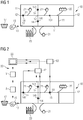
- a first embodiment of such a device 30 for pressure control in a supply network 10 is shown in FIG Fig. 2 .
- the Fig. 3 a slightly modified exemplary embodiment of such a device 30.
- the two exemplary embodiments differ essentially in the use of a different target value during the learning of the self-learning system SS.
- FIG. 2 the same supply network 10 as that in Fig. 1 .
- the description of the supply network 10 and the consumers connected to it refer to the Fig. 1 referenced.
- the Fig. 2 shows in addition to the supply network 10 and the consumers connected to it also a device 30 for Pressure regulation of the drinking water in the supply network 10.
- the three first sensors 14 are connected to a first detection unit E1.
- the first acquisition unit E1 is designed to acquire and forward the flow rates and / or pressures measured by the first sensors 14 at the first locations 141.
- the Fig. 2 a second acquisition unit E2. Analogously to the first acquisition unit E1, this is designed to acquire the flow rate and / or pressure measured by a second sensor 15 at the second location 151 in the supply network 10 and, as soon as required in the process, to forward it to a corresponding point.
- the self-learning system SS is in the Fig. 2
- the first embodiment shown is connected to the first acquisition unit E1 and the second acquisition unit E2. These connections are in Fig. 1 marked as dashed lines.
- the first detection unit E1 supplies the input data, namely the measured flow rates and / or pressures at the first locations 141 in the supply network 10. Based on this, it is the task of the self-learning system SS to predict or predict an (expected) pressure at another location in the supply network. to determine. This other location is the already mentioned second location 151, namely the location at which the second sensor 15 is located.
- the pressure at the second location 151 determined by the self-learning system SS will generally not yet match the actual pressure at this location.
- the pressure determined by the self-learning system SS is compared with a target value.
- this target value is the flow rate and / or pressure actually measured at the second location.
- the measurement of the flow rate and / or pressure at this location is advantageously carried out with the second sensor 15.
- the pressure calculated or measured by the second sensor 15 is detected by the second detection unit E2 and forwarded to the self-learning system SS.
- the pressure measured or calculated by the second sensor 15 is then compared with the previously determined / predicted value in the self-learning system. If the agreement is too low - which, as indicated above, should be the rule in particular at the start of training - new flow and / or pressure values are measured by the first sensors 14.
- the self-learning system SS tries to predict the actual pressure at the second location 151 as accurately as possible for these new flow rates and / or pressures.
- the self-learning system SS will correctly predict the pressure at the second location 151 in the second run based on what has been learned from the first run without major problems. During operation, however, the self-learning system SS must be able to make a correct prediction for the pressure at the second 151 location for the most varied of flow rates and / or pressures at the first locations 141.
- the described steps of a run are therefore: measuring the flow rates and / or pressures at the first locations 141; Predicting the pressure at the second location 151; and comparing the predicted pressure with the actual measured pressure.
- the termination criterion can For example, for ten consecutive runs, the difference between the pressure determined by the self-learning system SS at the second location 151 and the pressure actually present (determined based on the measurement of the second sensor 15 located at the second location 151) is less than 5%, in particular less than 2%, preferably less than 1%, must be.
- the supply network 10 is operated, also referred to as the use phase.
- the flow rates and / or pressures at the first locations 141 in the supply network 10 are again measured. This is done by means of the first sensors 14.
- the measured values are recorded by the first recording unit E1 and forwarded to the self-learning system SS, which is also referred to as the "learned system” SS in the context of this patent application after the learning phase has ended.
- the forwarding of the flow rates and / or pressures detected by the first detection unit E1 to the trained system SS is in Fig. 1 marked with a solid line - to distinguish the dashed connection during the learning phase.
- the learned system SS now makes a prediction with regard to the expected pressure at the second based on the measured flow rates and / or pressures at the first locations 141 Location 151 in the supply network 10. This prediction is made by a prediction unit V.
- the pump 16 is then controlled accordingly. If it turns out, for example, that the pressure at the second location 151 is higher than it has to be for supplying the relevant consumers with drinking water, the pump 16 reduces its pumping capacity. This reduces the pressure in the supply network 10 and, in particular, also at the second location 151, as a result of which the wear on the components of the supply network 10, the energy consumption of the pump 16 and any background leakages in the supply network 10 are reduced. If, on the other hand, it turns out, for example, that the pressure at the second location 151 is lower than is required for fire hydrants placed in the vicinity of the second location 151, the pump 16 increases its pumping capacity. This ensures a water pressure at the second location 151 which, in the event that water has to be taken from a fire hydrant placed in this area, is high enough for the requirements associated therewith.
- the pressure in the supply network 10 can in principle be regulated even more optimally.
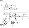
- the Fig. 3 shows a second embodiment of a device 30 for regulating the pressure in a supply network 10. It differs in the learning of the self-learning system SS from the device 30 of the first embodiment.
- the second exemplary embodiment only the measured flow rates and / or pressures at the first locations 141 are initially forwarded from the first detection unit E1 to the self-learning system SS during the learning phase.
- This in turn says or determines an expected pressure at the second location 151 in the supply network 10.
- This expected pressure it is not compared directly with the pressure determined at the second location 151, but with a simulated pressure at the second location 151. It is of great importance for successful learning of the self-learning system SS that the simulated flow rate at the second Location 151 is trustworthy, that is to say correct, since it represents the target value with which the self-learning system SS is learned. If the target value does not match reality, the learned system SS cannot logically map or predict reality correctly either.
- the simulation SIM is a hydraulic simulation.
- the pressures and other parameters e.g. flow rates, flow velocities, ...) in the supply network are simulated analytically or model-based on the basis of fluid mechanics.
- the challenge of a hydraulic simulation SIM is usually that it quickly becomes quite complex for supply networks that are relatively simple in topology.
- a series of input data IN is usually required for the hydraulic simulation SIM.
- the topology i.e. the arrangement and the course of the pipes 11 and nodes 12
- the flow rate and / or pressure at the inflow 13 into the supply network 10 the arrangement and type of consumers
- Substitute consumption profiles of the individual consumer types i.e. typical (or: representative) consumption profiles for the individual consumer types
- Properties of the pipes e.g. Coefficient of friction or inner diameter.
- the hydraulic simulation SIM simulates the expected pressure at the second location 151 and feeds this to the self-learning system SS.
- the simulated pressure at the second location 151 functions as a target value for the self-learning system SS and as a measure of how well the self-learning system SS has already been trained.
- the invention provides a method, a device and an arrangement with which the pressure in a supply network can be regulated in a simple manner with the aid of a self-learning system, the pressure not being measured at some locations in the supply network, but only by means of of the learned system is predicted.
Landscapes
- Engineering & Computer Science (AREA)
- Physics & Mathematics (AREA)
- Health & Medical Sciences (AREA)
- Theoretical Computer Science (AREA)
- General Physics & Mathematics (AREA)
- General Engineering & Computer Science (AREA)
- Life Sciences & Earth Sciences (AREA)
- Business, Economics & Management (AREA)
- General Health & Medical Sciences (AREA)
- Public Health (AREA)
- Water Supply & Treatment (AREA)
- Biomedical Technology (AREA)
- Computing Systems (AREA)
- Molecular Biology (AREA)
- Evolutionary Computation (AREA)
- Mathematical Physics (AREA)
- Software Systems (AREA)
- Data Mining & Analysis (AREA)
- Computational Linguistics (AREA)
- Biophysics (AREA)
- Economics (AREA)
- Artificial Intelligence (AREA)
- Automation & Control Theory (AREA)
- Fluid Mechanics (AREA)
- Mechanical Engineering (AREA)
- Hydrology & Water Resources (AREA)
- Strategic Management (AREA)
- Tourism & Hospitality (AREA)
- General Business, Economics & Management (AREA)
- Human Resources & Organizations (AREA)
- Primary Health Care (AREA)
- Marketing (AREA)
- Acoustics & Sound (AREA)
- Control Of Fluid Pressure (AREA)
- Control Of Positive-Displacement Pumps (AREA)
- Management, Administration, Business Operations System, And Electronic Commerce (AREA)
Priority Applications (5)
| Application Number | Priority Date | Filing Date | Title |
|---|---|---|---|
| EP19159109.8A EP3699700A1 (fr) | 2019-02-25 | 2019-02-25 | Régulation de pression dans un un réseau d'alimentation électrique |
| US17/422,298 US11906987B2 (en) | 2019-02-25 | 2020-02-18 | Pressure control in a supply grid |
| CN202080016752.0A CN113424114A (zh) | 2019-02-25 | 2020-02-18 | 供应网中的压力控制 |
| PCT/EP2020/054166 WO2020173751A1 (fr) | 2019-02-25 | 2020-02-18 | Régulation de pression dans un réseau de distribution |
| EP20707015.2A EP3877816B1 (fr) | 2019-02-25 | 2020-02-18 | Régulation de pression dans un un réseau d'alimentation électrique |
Applications Claiming Priority (1)
| Application Number | Priority Date | Filing Date | Title |
|---|---|---|---|
| EP19159109.8A EP3699700A1 (fr) | 2019-02-25 | 2019-02-25 | Régulation de pression dans un un réseau d'alimentation électrique |
Publications (1)
| Publication Number | Publication Date |
|---|---|
| EP3699700A1 true EP3699700A1 (fr) | 2020-08-26 |
Family
ID=65635430
Family Applications (2)
| Application Number | Title | Priority Date | Filing Date |
|---|---|---|---|
| EP19159109.8A Withdrawn EP3699700A1 (fr) | 2019-02-25 | 2019-02-25 | Régulation de pression dans un un réseau d'alimentation électrique |
| EP20707015.2A Active EP3877816B1 (fr) | 2019-02-25 | 2020-02-18 | Régulation de pression dans un un réseau d'alimentation électrique |
Family Applications After (1)
| Application Number | Title | Priority Date | Filing Date |
|---|---|---|---|
| EP20707015.2A Active EP3877816B1 (fr) | 2019-02-25 | 2020-02-18 | Régulation de pression dans un un réseau d'alimentation électrique |
Country Status (4)
| Country | Link |
|---|---|
| US (1) | US11906987B2 (fr) |
| EP (2) | EP3699700A1 (fr) |
| CN (1) | CN113424114A (fr) |
| WO (1) | WO2020173751A1 (fr) |
Cited By (4)
| Publication number | Priority date | Publication date | Assignee | Title |
|---|---|---|---|---|
| CN114753451A (zh) * | 2022-05-16 | 2022-07-15 | 重庆金越水务有限公司 | 用于低中高楼层的恒压供水系统及方法 |
| CN115355449A (zh) * | 2022-08-16 | 2022-11-18 | 上海肯特仪表股份有限公司 | 一种管道流量的监测方法、电磁流量计及系统 |
| CN115355447A (zh) * | 2022-10-20 | 2022-11-18 | 成都秦川物联网科技股份有限公司 | 一种基于物联网的智慧燃气门站调压优化方法和系统 |
| CN117850491A (zh) * | 2024-03-06 | 2024-04-09 | 韵京厦(四川)能源科技研究院(有限合伙) | 用于燃气输配的自动调压控制方法及系统 |
Families Citing this family (6)
| Publication number | Priority date | Publication date | Assignee | Title |
|---|---|---|---|---|
| EP3699700A1 (fr) * | 2019-02-25 | 2020-08-26 | Siemens Aktiengesellschaft | Régulation de pression dans un un réseau d'alimentation électrique |
| US12147212B2 (en) * | 2021-12-21 | 2024-11-19 | Applied Materials, Inc. | Diagnostic methods for substrate manufacturing chambers using physics-based models |
| CN114595832A (zh) * | 2022-03-04 | 2022-06-07 | 河北利万信息科技有限公司 | 一种供水管网特性参数的自学习方法 |
| CN116050033B (zh) * | 2022-11-02 | 2026-03-17 | 上海电机学院 | 一种实时水网压力平衡控制的方法和系统 |
| CN115681821B (zh) * | 2022-12-13 | 2023-04-07 | 成都秦川物联网科技股份有限公司 | 用于智慧燃气设备管理的加臭自动控制方法和物联网系统 |
| CN119373202B (zh) * | 2024-12-27 | 2025-03-07 | 深圳市朗格瑞实业发展有限公司 | 一种泵房控制方法、装置、电子设备及存储介质 |
Citations (4)
| Publication number | Priority date | Publication date | Assignee | Title |
|---|---|---|---|---|
| US5448476A (en) * | 1993-06-17 | 1995-09-05 | Kabushiki Kaisha Toshiba | Distributed water flow predicting device |
| US20080300803A1 (en) * | 2007-05-29 | 2008-12-04 | Drake David A | Leak detection system and method |
| US7920983B1 (en) * | 2010-03-04 | 2011-04-05 | TaKaDu Ltd. | System and method for monitoring resources in a water utility network |
| EP3120201A1 (fr) | 2014-03-21 | 2017-01-25 | Siemens Aktiengesellschaft | Procédé pour la régulation de la pression dans un réseau d'alimentation, dispositif et réseau d'alimentation |
Family Cites Families (23)
| Publication number | Priority date | Publication date | Assignee | Title |
|---|---|---|---|---|
| JPS5350863A (en) * | 1976-10-20 | 1978-05-09 | Hitachi Ltd | Demand quantity estimating apparatus for flow rate pressure controlling in piping network |
| JPS58700A (ja) * | 1981-06-26 | 1983-01-05 | Hitachi Ltd | 流体輸送システムの制御方式 |
| US6112137A (en) * | 1998-02-04 | 2000-08-29 | Gas Research Institute | Adaptive system for predictive control of district pressure regulators |
| US6701223B1 (en) * | 2000-09-11 | 2004-03-02 | Advantica, Inc. | Method and apparatus for determining optimal control settings of a pipeline |
| JP3795775B2 (ja) * | 2001-07-16 | 2006-07-12 | 株式会社山武 | 下水流入量予測装置および方法、サーバ装置 |
| US6697713B2 (en) * | 2002-01-30 | 2004-02-24 | Praxair Technology, Inc. | Control for pipeline gas distribution system |
| US7317404B2 (en) * | 2004-01-14 | 2008-01-08 | Itron, Inc. | Method and apparatus for collecting and displaying consumption data from a meter reading system |
| WO2006014372A2 (fr) * | 2004-07-02 | 2006-02-09 | Ferber Philip E | Logiciel d'optimisation de reglage de debit de conduite et procedes |
| US7814936B2 (en) * | 2005-11-16 | 2010-10-19 | Fisher Controls International Llc | Sound pressure level feedback control |
| US7707125B2 (en) * | 2005-12-07 | 2010-04-27 | Controlsoft, Inc. | Utility management system and method |
| BRPI0807862B8 (pt) * | 2007-01-24 | 2023-01-31 | I2O Water Ltd | Controlador e sistema de controle para uma válvula redutora de pressão |
| US9493931B2 (en) * | 2008-12-30 | 2016-11-15 | I20 Water Limited | Mains water supply processing |
| CA2843209C (fr) * | 2011-08-05 | 2019-09-24 | Fisher Controls International Llc | Procedes et appareil pour commande en boucle de niveau |
| EP2778296B1 (fr) * | 2013-03-11 | 2018-04-25 | Grundfos Holding A/S | Système de pompe |
| GB2545899B (en) * | 2015-12-21 | 2018-07-25 | Imperial Innovations Ltd | Management of liquid conduit systems |
| EP3327206B1 (fr) * | 2016-11-25 | 2020-03-25 | Tata Consultancy Services Limited | Classement de tuyaux pour la maintenance dans des réseaux de tuyaux utilisant des mesures hydrauliques approximatives |
| WO2018225032A1 (fr) * | 2017-06-09 | 2018-12-13 | Emagin Clean Technologies Inc. | Modélisation et commande prédictives d'infrastructure de ressources d'eau |
| EP3422122B1 (fr) * | 2017-06-29 | 2022-09-28 | Grundfos Holding A/S | Module de formation de modèles pour créer un modèle de commande du système de régulation de pression d'un réseau d'alimentation en eau |
| US10745893B2 (en) * | 2017-07-19 | 2020-08-18 | Google Llc | User friendly systems and devices facilitating water conservation in the smart home |
| EP3588234B1 (fr) * | 2018-06-21 | 2021-03-17 | Grundfos Holding A/S | Système et procédé de commande d'une alimentation en eau à partir d'au moins deux lignes d'entrée séparées dans un secteur d'un réseau d'alimentation en eau |
| US11499856B2 (en) * | 2018-09-10 | 2022-11-15 | Phyn Llc | Freeze prediction, detection, and mitigation |
| US11054295B2 (en) * | 2019-02-14 | 2021-07-06 | Sensus Spectrum, Llc | Pressure regulating devices and related systems and methods |
| EP3699700A1 (fr) * | 2019-02-25 | 2020-08-26 | Siemens Aktiengesellschaft | Régulation de pression dans un un réseau d'alimentation électrique |
-
2019
- 2019-02-25 EP EP19159109.8A patent/EP3699700A1/fr not_active Withdrawn
-
2020
- 2020-02-18 US US17/422,298 patent/US11906987B2/en active Active
- 2020-02-18 EP EP20707015.2A patent/EP3877816B1/fr active Active
- 2020-02-18 WO PCT/EP2020/054166 patent/WO2020173751A1/fr not_active Ceased
- 2020-02-18 CN CN202080016752.0A patent/CN113424114A/zh active Pending
Patent Citations (4)
| Publication number | Priority date | Publication date | Assignee | Title |
|---|---|---|---|---|
| US5448476A (en) * | 1993-06-17 | 1995-09-05 | Kabushiki Kaisha Toshiba | Distributed water flow predicting device |
| US20080300803A1 (en) * | 2007-05-29 | 2008-12-04 | Drake David A | Leak detection system and method |
| US7920983B1 (en) * | 2010-03-04 | 2011-04-05 | TaKaDu Ltd. | System and method for monitoring resources in a water utility network |
| EP3120201A1 (fr) | 2014-03-21 | 2017-01-25 | Siemens Aktiengesellschaft | Procédé pour la régulation de la pression dans un réseau d'alimentation, dispositif et réseau d'alimentation |
Cited By (8)
| Publication number | Priority date | Publication date | Assignee | Title |
|---|---|---|---|---|
| CN114753451A (zh) * | 2022-05-16 | 2022-07-15 | 重庆金越水务有限公司 | 用于低中高楼层的恒压供水系统及方法 |
| CN115355449A (zh) * | 2022-08-16 | 2022-11-18 | 上海肯特仪表股份有限公司 | 一种管道流量的监测方法、电磁流量计及系统 |
| CN115355447A (zh) * | 2022-10-20 | 2022-11-18 | 成都秦川物联网科技股份有限公司 | 一种基于物联网的智慧燃气门站调压优化方法和系统 |
| CN115355447B (zh) * | 2022-10-20 | 2023-01-06 | 成都秦川物联网科技股份有限公司 | 一种基于物联网的智慧燃气门站调压优化方法和系统 |
| US11893518B2 (en) | 2022-10-20 | 2024-02-06 | Chengdu Qinchuan Iot Technology Co., Ltd. | Methods and systems of optimizing pressure regulation at intelligent gas gate stations based on internet of things |
| US12481934B2 (en) | 2022-10-20 | 2025-11-25 | Chengdu Qinchuan Iot Technology Co., Ltd. | Method and system for determining pressure regulation scheme at intelligent gas gate station based on internet of things |
| CN117850491A (zh) * | 2024-03-06 | 2024-04-09 | 韵京厦(四川)能源科技研究院(有限合伙) | 用于燃气输配的自动调压控制方法及系统 |
| CN117850491B (zh) * | 2024-03-06 | 2024-05-10 | 韵京厦(四川)能源科技研究院(有限合伙) | 用于燃气输配的自动调压控制方法及系统 |
Also Published As
| Publication number | Publication date |
|---|---|
| CN113424114A (zh) | 2021-09-21 |
| US11906987B2 (en) | 2024-02-20 |
| EP3877816B1 (fr) | 2024-05-29 |
| EP3877816A1 (fr) | 2021-09-15 |
| US20220083083A1 (en) | 2022-03-17 |
| EP3877816C0 (fr) | 2024-05-29 |
| WO2020173751A1 (fr) | 2020-09-03 |
Similar Documents
| Publication | Publication Date | Title |
|---|---|---|
| EP3877816B1 (fr) | Régulation de pression dans un un réseau d'alimentation électrique | |
| EP3699569A1 (fr) | Détection d'une fuite dans un réseau d'alimentation | |
| EP3120201B1 (fr) | Procédé et dispositif de régulation de la pression dans un réseau de distribution d'un fluide | |
| DE112012001851T5 (de) | Ermitteln von Fluid-Leckagevolumen in Pipelines | |
| DE112019002262T5 (de) | Fluid-leckage-erfassungs-system und fluid-druck-system | |
| EP2971768B2 (fr) | Développement d'un modèle supérieur pour contrôler et/ou surveiller un système de compresseurs | |
| EP2588925B1 (fr) | Procédé et dispositif pour déterminer des paramètres de modèle servant à la régulation d'un bloc de centrale à vapeur, unité de régulation pour un générateur de vapeur et produit de programme informatique | |
| EP3232282A1 (fr) | Dispositif de diagnostic et procede de surveillance du fonctionnement d'une installation technique | |
| DE102007058211A1 (de) | Verfahren zum Betrieb eines strömungstechnischen Leitungssystems | |
| DE2161353C2 (de) | Vorrichtung zur Übertragung von Meßwerten aus einem Bohrloch mittels der Bohrspülung | |
| DE102018114710B4 (de) | Erkennen mangelhafter Sitz-Integrität bei einem Stellventil | |
| DE102014001413A1 (de) | Verfahren zur Bestimmung der Systemkennlinie eines Verteilernetzes | |
| EP3121672B1 (fr) | Procede et dispositif de diagnostic destines a la surveillance du fonctionnement d'un circuit regulateur | |
| EP1462901A2 (fr) | Procédé et dispositif pour la régulation ou la commande d'un processus de variation de charge thermique dans une piece non déformable et/ou à paroi épaisse traversée par un fluide dans une installation thermique | |
| WO2022152752A1 (fr) | Procédé de fourniture d'au moins un élément d'informations relatives à un système hydraulique | |
| WO2014140261A1 (fr) | Entrée du schéma de tuyauterie et d'instrumentation (p&id) | |
| EP4040053A1 (fr) | Dispositif et procédé de détermination d'une valeur de consommation thermique d'un consommateur thermique d'une installation | |
| EP4469704A1 (fr) | Procédé de diagnostic d'un composant par émission acoustique | |
| DE102020210922A1 (de) | Verfahren und Anordnung zur Durchflussmessung | |
| DE102014202558A1 (de) | Digitalhydraulischer druckregler und überprüfungsverfahren eines digitalhydraulischen druckreglers | |
| EP3874335A1 (fr) | Procédé et dispositif de diagnostic pour déterminer des effets de frottement dans des soupapes à réglage continu | |
| DE4110934A1 (de) | Verfahren fuer aufgaben der steuerung in vermaschten hydraulischen rohrleitungsnetzen | |
| DE102024128801A1 (de) | Verfahren zum Kalibrieren einer Zielmetrik einer Steuergerätefunktion | |
| EP3483513A1 (fr) | Procédé de fonctionnement d'une installation de chauffage et installation de chauffage | |
| EP2439602A1 (fr) | Procédé destiné à développer un régulateur de processus |
Legal Events
| Date | Code | Title | Description |
|---|---|---|---|
| PUAI | Public reference made under article 153(3) epc to a published international application that has entered the european phase |
Free format text: ORIGINAL CODE: 0009012 |
|
| STAA | Information on the status of an ep patent application or granted ep patent |
Free format text: STATUS: THE APPLICATION HAS BEEN PUBLISHED |
|
| AK | Designated contracting states |
Kind code of ref document: A1 Designated state(s): AL AT BE BG CH CY CZ DE DK EE ES FI FR GB GR HR HU IE IS IT LI LT LU LV MC MK MT NL NO PL PT RO RS SE SI SK SM TR |
|
| AX | Request for extension of the european patent |
Extension state: BA ME |
|
| STAA | Information on the status of an ep patent application or granted ep patent |
Free format text: STATUS: THE APPLICATION IS DEEMED TO BE WITHDRAWN |
|
| 18D | Application deemed to be withdrawn |
Effective date: 20210227 |