EP3120370B1 - Dispositif d'interruption de circuit - Google Patents
Dispositif d'interruption de circuit Download PDFInfo
- Publication number
- EP3120370B1 EP3120370B1 EP15714029.4A EP15714029A EP3120370B1 EP 3120370 B1 EP3120370 B1 EP 3120370B1 EP 15714029 A EP15714029 A EP 15714029A EP 3120370 B1 EP3120370 B1 EP 3120370B1
- Authority
- EP
- European Patent Office
- Prior art keywords
- insulating case
- tubular insulating
- vacuum interrupter
- ceramic
- caps
- Prior art date
- Legal status (The legal status is an assumption and is not a legal conclusion. Google has not performed a legal analysis and makes no representation as to the accuracy of the status listed.)
- Active
Links
Images






Classifications
-
- H—ELECTRICITY
- H01—ELECTRIC ELEMENTS
- H01H—ELECTRIC SWITCHES; RELAYS; SELECTORS; EMERGENCY PROTECTIVE DEVICES
- H01H33/00—High-tension or heavy-current switches with arc-extinguishing or arc-preventing means
- H01H33/60—Switches wherein the means for extinguishing or preventing the arc do not include separate means for obtaining or increasing flow of arc-extinguishing fluid
- H01H33/66—Vacuum switches
- H01H33/662—Housings or protective screens
- H01H33/66207—Specific housing details, e.g. sealing, soldering or brazing
-
- H—ELECTRICITY
- H01—ELECTRIC ELEMENTS
- H01H—ELECTRIC SWITCHES; RELAYS; SELECTORS; EMERGENCY PROTECTIVE DEVICES
- H01H33/00—High-tension or heavy-current switches with arc-extinguishing or arc-preventing means
- H01H33/60—Switches wherein the means for extinguishing or preventing the arc do not include separate means for obtaining or increasing flow of arc-extinguishing fluid
- H01H33/66—Vacuum switches
- H01H33/662—Housings or protective screens
- H01H33/66207—Specific housing details, e.g. sealing, soldering or brazing
- H01H2033/66223—Details relating to the sealing of vacuum switch housings
Definitions
- the present invention relates to a circuit interrupting device used for current breaking or switching and more particularly to a vacuum interrupter for high or medium voltage application.
- Vacuum interrupters generally comprise an extinguishing chamber in which a low pressure prevails.
- the chamber is formed by an insulating case, sometimes also called housing or bottle, usually made from one or more cylinders made of ceramic or glass-ceramic, which constitute a generally tubular first central part.
- Typical ceramics used for vacuum interrupter are manufactured mainly from alumina (Al 2 O 3 ) and a small percentage of silica (SiO 2 ) up to about 6%.
- This insulating case is sealed off at its ends by caps, usually made from metal.
- the metal caps are usually brazed to the ceramic insulating case to form a vacuum tight joint seal, using an active braze material or after a well-controlled metallization step on the end surfaces of the ceramic part(s).
- a pair of contacts is located in the extinguishing chamber. These contacts are able to move between a closed position in which the electric current can flow and an open position in which the two contacts are separated so as to interrupt the current flow.
- one contact is stationary, fixed in a secured manner to one of the caps sealing the chamber, and the other contact is movable within the chamber.
- a bellows surrounds the movable contact and enables the inside of the chamber to be mechanically sealed and airtight so as to remain at a low pressure.
- ceramic or glass-ceramic for the insulating case is ideal for vacuum interrupters because of its mechanical strength, its low porosity, its low out-gassing, its ability to form vacuum tight seals and its excellent high-voltage withstand characteristics. Moreover, ceramics (or glass-ceramic) present also a high resistance to environmental conditions, such as pollution or O 3 corrosion.
- Vacuum interrupters must also exhibit a high enough dielectric strength externally to withstand the high voltage applied between the interrupter open contacts (terminals). A free air space around the interrupter may not be sufficient, in particular when the operating voltage is medium or high.
- a dielectric environment such as a tightly sealed enclosure containing a dielectric fluid, like SF 6 or oil or even pressurised air.
- these solutions are cumbersome to implement and to manage while in use.
- insulating gas could be suitable for use in fixed indoor substations, it is not quite so on the outdoor rolling stock where exposure to harsh environment conditions could lead to breakage of the sealed enclosure and leaking of the gas.
- Another option to ensure proper external insulation of the vacuum interrupter can be realised by casting or coating of the vacuum interrupter with a suitable encapsulating material such as silicone rubber, epoxy or other suitable polymer.
- a bonding agent can be used between the ceramic of the main part of the interrupter and the insulating material for proper adhesion.
- the ceramic part(s), the metal caps and the polymer coating present each different thermal expansion coefficient which can cause cracking, or even breaking of the insulating enclosure.
- epoxy and other polymer do not age well and are sensitive to harsh environment condition such as pollution or O 3 corrosion.
- WO 2012/042294 discloses a vacuum interrupter with selective external encapsulation: external encapsulation is provided for at least one contact terminal or electrode extending from the metallic end cap of the corresponding said contacts and covering the ceramic part by an overlapping distance (around 12 to 18 mm).
- the encapsulating material is a solid insulation such as silicone rubber.
- WO 2010/000769 discloses a vacuum switching tube comprising a housing with at least one ceramic housing section and metal housing parts, wherein transition areas between the at least one ceramic housing section and the metal housing parts are covered by way of an insulating material.
- the insulating layer is made of an insulating material such as a polymer resin or a thermoplastic and additives that influence the insulating properties of the insulating material.
- JP 2003 031090 discloses another example of a vacuum switching tube comprising a rubber layer at the junction of the insulating cylinders and the end plates of the tube. As with the solution of WO 2012/042294 , these two examples of vacuum switching interrupter are not made to withstand outdoor atmospheric conditions due to the use of polymer or rubber.
- the object of the present invention is a vacuum interrupter according to claim 1 and claim 10.
- a vacuum interrupter 1 according to the invention is designed for use in a circuit-breaking device to perform switching and/or breaking in an electric circuit.
- the vacuum interrupter 1 according to the invention is preferably arranged to operate at high or medium voltage.
- the vacuum interrupter 1 generally comprises a sealed extinguishing chamber 2 in which a controlled low pressure of air or another dielectric fluid preferably prevails, i.e. a vacuum.
- the chamber 2 is defined by a tubular insulating case.
- the tubular insulating case is preferably formed by two insulating cylinders 3, 4 made from ceramic or glass-ceramic.
- a conducting cap 51, 52 closes each open end of the chamber 2.
- the caps 51, 52 are made of metal and each comprises a substantially flat base-plate essentially perpendicular to the longitudinal axis AA of the interrupter 1 and extended on its periphery by an essentially orthogonal sidewall 61, 62.
- the conducting caps 51, 52 are secured in a tightly sealed manner to their corresponding ceramic cylinders 3, 4 in a sealing area 7.
- the sealing area 7 is limited to a line that corresponds to a braze of the peripheral wall 61, 62 of the caps 51, 52 on their respective ceramic cylinders 3, 4.
- any other known technique can be used to effectively seal the caps 51, 52 to their respective ceramic cylinders 3, 4.
- the chamber 2 bounded by the ceramic cylinders 3, 4 and caps 51, 52 comprises a pair of acting contacts 101, 102 that are movable with respect to one another along the longitudinal axis AA of the vacuum interrupter 1.
- Each contact 101, 102 comprises a contact pad 121, 122 made from suitable material fixed onto a longitudinal electrode 141, 142.
- a first contact 101 is stationary and securely fixed to one of the end caps 51 to which its electrode 141 is coupled, for example by welding, brazing or mechanical assembly.
- the second contact 102 is mounted inside the chamber 2 with its electrode 142 so as to be able to move through the other cap 52.
- a sealing metallic bellows 16 is fitted between the movable electrode 142, to which it can for example be welded at one end, and the corresponding cap 52, thereby sealing the opening of the cap 52 of the chamber 2.
- a metallic bellows shield 18 can be fitted around the sealing bellows 16, at the level of the end thereof coupled to the electrode 142, to protect the said bellows 16 against projections caused by the arc during a current interruption process.
- the tightly sealed chamber 2 preferably further comprises a metallic shield 20 positioned at the level of the contact pads 121, 122 whatever the position thereof in order to protect the insulating ceramic cylinders 3, 4 against metallic vapour or any projections that might occur during arcing.
- the metallic shield 20 is held between the two ceramic cylinders 3, 4 and secured to said cylinders by brazing or any other suitable means ensuring proper sealing.
- the tubular insulating case is made in one piece for example, the metallic shield 20 could be secured in a fixed manner to one of the caps 51, 52.
- a vacuum interrupter 1 as described above is pictured for example in figures 1a to 1c . It is well known to the person of ordinary skills in the art and has been described as an example only.
- the internal components of the interrupter (contacts 101, 102, cylinders 3, 4, caps 51, 52, shields 18, 20) are designed to optimize the thermal and dielectric properties and the mechanical strength of the interrupter 1. These internal design features are well known to the person of ordinary skills in the art and will not be described in further detail.
- the tubular insulating case is extended on its outside part so as to surround and enclose the caps 51, 52 without changing the dimension and the components of the vacuum interrupter. Hence, external dielectric performances of the vacuum interrupter are improved.
- the insulating tubular case of the vacuum interrupter 1 is designed to surround and enclose the caps 51, 52.
- the tubular insulating case extends along the sidewall 61, 62 of said conducting caps 51, 52.
- ceramic or glass-ceramic is an insulating material, the external insulating distance between the caps 51, 52 is increased and thus the dielectric performance of the interrupter is enhanced.
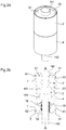
- the ceramic cylinders 3', 4' forming the tubular insulating case are each made in one piece so that they each extend beyond their respective caps 51, 52 and in particular along the sidewall 61, 62 of said caps.
- the said caps 51, 52 are then wholly enclosed by said cylinders 3', 4' ( figure 2b ).
- the extension portions 31, 41 of the cylinders 3', 4' surrounding the sidewall 61, 62 of the caps 51, 52 have a smaller thickness than the rest of the cylinders 3', 4'.
- the cylinders 3', 4' further comprise an inner flange 30, 40 which corresponds to the sealing area 7 and on which the walls 61, 62 of the caps 51, 52 are brazed or suitably sealed.
- the extension portions 31, 41 may extend from this flange 30, 40 to surround the caps 51, 52.
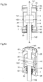
- Figure 2d is an enlarged view of the gap 8 between the metal caps 51, 52 and the extension portions 31, 41 of the cylinders 3', 4'.
- the gap 8 between the metal caps 51, 52 and the extension portions 31, 41 of the cylinders 3', 4' can be filled with a suitable filling resin 9 to supress the sharp corner and reduce the electric field enhancement.
- the said filling resin 9 is an epoxy-resin or rubber (silicone rubber, polyurethane...) or a suitable semi-conductive resin.
- the said filling resin 9 is a metal-filled or ceramic- (micro- or nano-powder) filled epoxy (Al 2 O 3 -filled epoxy, TiO 2 -filled epoxy or SiO 2 -filled epoxy composites, for example).
- the angle 81 at the bottom of the gap 8, defined as the angle between the inner flange 30, 40 and the inner walls of the extension portion 31, 41, is not sharp but rather rounded as illustrated in the figures 2d an 2e. This is to reduce the electric field enhancement.
- the cylinders 3', 4' present the same external diameter along their length.
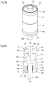
- Figures 3a and 3b illustrate a variant in which the cylinders 3', 4' each present a portion with a larger external diameter forming a bulge 33, 43 near the sealing area 7 and the flanges 30, 40. This has for effect to diverge further the electric potential lines close to the sealing (brazing) area 7 (metal-ceramic edges).
- the extension portions 31, 41 of the cylinders 3', 4' surrounding the caps 51, 52 present a thickness essentially equal to the thickness of the rest of the cylinders 3', 4'.
- the said portions 31', 41' have an internal and external diameters greater than the rest of the cylinders 3', 4' which result in a shoulder 33', 43' being formed on the external part of the cylinders 3', 4' opposite the inner flanges 30, 40 and the sealing areas 7.
- This specific variant presents the same effect as obtained by the bulge 33, 43, and moreover brings additional mechanical strength to the extension potion 31', 41'.
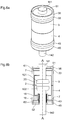
- FIGs 5a to 6b illustrate a second embodiment of a vacuum interrupter according to the invention.
- This particular embodiment aims to apply the essential principle of the invention to existing standard ceramic or glass-ceramic vacuum interrupters (i.e. such as shown in figures 1a to 1c ).
- the tubular insulating case is extended to surround the caps 51, 52 by affixing extension portions 35, 45 to the cylinders 3, 4.
- the said extension portions 35, 45 are essentially tubular in shape and made of ceramic or glass-ceramic.
- the extension portions 35, 45 are conformed to overlap part of their respective cylinders 3, 4 (see figure 5b ) and to wholly surround the caps 51, 52 and extend along the sidewalls 61, 62 of said caps 51, 52.
- the extension portions 35, 45 are tightly fixed or glued to their respective cylinders 3, 4 by any suitable means.
- the gluing material can be an epoxy or metal-filled epoxy adhesive suitable for ceramic bonding.
- the adhesive is preferably a polymer composite adhesive such as ceramic micro- or nano-powder filled epoxy (Al 2 O 3 -filled epoxy, TiO 2 -filled epoxy or SiO 2 -filled epoxy composites, for example).
- a polymer composite adhesive such as ceramic micro- or nano-powder filled epoxy (Al 2 O 3 -filled epoxy, TiO 2 -filled epoxy or SiO 2 -filled epoxy composites, for example).
- Al 2 O 3 -filled epoxy, TiO 2 -filled epoxy or SiO 2 -filled epoxy composites, for example The advantages of these epoxy-filled composite is their higher dielectric constant e r (relative permittivity) than epoxy (e r ⁇ 6 for the composite instead of e r ⁇ 3,5 for epoxy).
- the extension portions 35, 45 present each a portion of larger thickness forming a bulge 33, 43 near the sealing area 7 where the caps 51, 52 are brazed onto the cylinders 3, 4.
- the gap between the metal caps 51, 52 and the extension portions 35, 45 of the cylinders 3, 4 can be filled with a suitable filling resin such as described above with respect to the first embodiment.
Landscapes
- High-Tension Arc-Extinguishing Switches Without Spraying Means (AREA)
- Gas-Insulated Switchgears (AREA)
Claims (13)
- Interrupteur à vide (1) comprenant un boîtier isolant tubulaire (3', 4') s'étendant le long d'un axe longitudinal (AA), deux capuchons conducteurs (51, 52) chacun solidement fixé à une extrémité ouverte du boîtier isolant tubulaire (3', 4') au niveau d'une zone d'étanchéité (7) destinée à former une chambre hermétiquement étanche (2), caractérisée en ce que le boîtier isolant tubulaire (3', 4') comprend deux parties d'extension (31, 41) en matériau isolant, chacune s'étendant essentiellement à partir de la zone d'étanchéité (7) le long de l'axe longitudinal (AA) au-delà d'un capuchon conducteur correspondant (51, 52) pour enfermer et entourer complètement ledit capuchon conducteur (51, 52); et en ce que les parties d'extension (31, 41) sont fabriquées d'une seule pièce avec le boîtier isolant tubulaire (3', 4').
- Interrupteur à vide (1) selon la revendication 1, caractérisé en ce que le boîtier isolant tubulaire (3', 4') et les parties d'extension (31, 41) présentent sur leur surface extérieure un renflement (33, 43) en face de chacune des zones d'étanchéité (7) où les capuchons (51, 52) sont respectivement scellés au boîtier isolant tubulaire (3', 4').
- Interrupteur à vide (1) selon la revendication 1, caractérisé en ce que les parties d'extension (31, 41) sont tubulaires, ont essentiellement la même épaisseur que le boîtier isolant tubulaire (3', 4') et un diamètre intérieur et un diamètre extérieur plus grands que le boîtier isolant tubulaire, de telle sorte qu'un épaulement (33', 43') est formé à l'extérieur dudit boîtier isolant tubulaire en regard de chacune des zones d'étanchéité (7) où les capuchons (51, 52) sont respectivement scellés au boîtier isolant tubulaire (3', 4').
- Interrupteur à vide (1) selon l'une quelconque des revendications précédentes, caractérisé en ce qu'il y a un espace (8) entre les capuchons conducteurs (51, 52) et les parties d'extension du boîtier isolant tubulaire.
- Interrupteur à vide (1) selon la revendication 4, caractérisé en ce que cet espace (8) est rempli d'une résine de remplissage (9).
- Interrupteur à vide (1) selon la revendication 5, caractérisé en ce que ladite résine de remplissage (9) est soit une résine époxy, soit un caoutchouc (caoutchouc silicone, polyuréthane ...) ou une résine semi-conductrice ou une résine époxy chargée de céramique ou de métal.
- Interrupteur à vide (1) selon l'une quelconque des revendications précédentes, caractérisé en ce que le boîtier isolant tubulaire (3', 4') comprend en outre une bride intérieure (30, 40) correspondant chacune à la zone d'étanchéité (7) et sur lequel les parois (61, 62) des capuchons 51, 52 sont brasées ou convenablement scellées;
et en ce que l'angle (81) entre la bride intérieure (30, 40) et lesdites parois de la partie d'extension (31, 41) est arrondi. - Interrupteur à vide (1) selon l'une quelconque des revendications précédentes, caractérisé en ce que le boîtier isolant tubulaire est en céramique ou vitrocéramique.
- Interrupteur à vide (1) selon l'une quelconque des revendications précédentes, caractérisé en ce que le boîtier isolant tubulaire est constitué de deux cylindres (3 ', 4 ') scellés ensemble pour former un boîtier tubulaire.
- Interrupteur à vide (1) comprenant un boîtier isolant tubulaire (3', 4') s'étendant le long d'un axe longitudinal (AA), deux capuchons conducteurs (51, 52) chacun solidement fixé à une extrémité ouverte du boîtier isolant tubulaire (3', 4') au niveau d'une zone d'étanchéité (7) pour former une chambre hermétiquement étanche (2), le boîtier isolant tubulaire (3, 4) étant réalisé en céramique ou vitrocéramique, caractérisé en ce qu'il comprend deux parties d'extension (35, 45) en céramique ou en vitrocéramique; en ce que les deux parties d'extension (35, 45) sont fixées fermement au boîtier isolant tubulaire et recouvrent une partie dudit boîtier isolant tubulaire près de la zone d'étanchéité (7); et en ce que les deux parties d'extension (35, 45) s'étendent essentiellement depuis la zone d'étanchéité (7) le long de l'axe longitudinal (AA) et enferment et entourent chacune un capuchon conducteur correspondant (51, 52).
- Interrupteur à vide (1) selon la revendication 10, caractérisé en ce qu'il y a un espace (8) entre les capuchons conducteurs (51, 52) et les parties d'extension du boîtier isolant tubulaire.
- Interrupteur à vide (1) selon la revendication 11, caractérisé en ce que cet espace (8) est rempli d'une résine de remplissage (9).
- Interrupteur à vide (1) selon la revendication 12, caractérisé en ce que ladite résine de remplissage (9) est soit une résine époxy, soit un caoutchouc (caoutchouc silicone, polyuréthane ...) ou une résine semi-conductrice ou une résine époxy chargée de céramique ou de métal.
Applications Claiming Priority (2)
| Application Number | Priority Date | Filing Date | Title |
|---|---|---|---|
| EP14160204 | 2014-03-17 | ||
| PCT/IB2015/051809 WO2015140674A1 (fr) | 2014-03-17 | 2015-03-12 | Dispositif d'interruption de circuit |
Publications (2)
| Publication Number | Publication Date |
|---|---|
| EP3120370A1 EP3120370A1 (fr) | 2017-01-25 |
| EP3120370B1 true EP3120370B1 (fr) | 2019-04-24 |
Family
ID=50277131
Family Applications (1)
| Application Number | Title | Priority Date | Filing Date |
|---|---|---|---|
| EP15714029.4A Active EP3120370B1 (fr) | 2014-03-17 | 2015-03-12 | Dispositif d'interruption de circuit |
Country Status (7)
| Country | Link |
|---|---|
| US (1) | US10074496B2 (fr) |
| EP (1) | EP3120370B1 (fr) |
| JP (1) | JP2017511568A (fr) |
| KR (1) | KR102517402B1 (fr) |
| CN (1) | CN106133869B (fr) |
| RU (1) | RU2016140649A (fr) |
| WO (1) | WO2015140674A1 (fr) |
Families Citing this family (11)
| Publication number | Priority date | Publication date | Assignee | Title |
|---|---|---|---|---|
| DE102016218316A1 (de) * | 2016-09-23 | 2018-03-29 | Siemens Aktiengesellschaft | Vakuumschalter |
| CN108321000B (zh) * | 2018-04-12 | 2024-01-02 | 大连理工大学 | 一种用于自均压式多断口真空断路器的真空灭弧室 |
| CN113474865B (zh) * | 2019-02-06 | 2025-01-28 | 株式会社明电舍 | 真空断路器 |
| US12266490B2 (en) | 2019-04-26 | 2025-04-01 | G & W Electric Company | Modular recloser |
| US12112906B2 (en) | 2019-04-26 | 2024-10-08 | G & W Electric Company | Integrated switchgear assembly |
| PH12021552689A1 (en) | 2019-04-26 | 2022-03-14 | G & W Electric | Switchgear with overmolded dielectric material |
| WO2020219905A1 (fr) | 2019-04-26 | 2020-10-29 | G & W Electric Company | Appareillage de commutation avec ensemble de déclenchement manuel et verrouillage mécanique |
| EP3780056B1 (fr) * | 2019-08-16 | 2025-09-24 | Siemens Aktiengesellschaft | Élément isolant de ventilation pour unités d'interrupteur, appareil de commutation et appareillage comprenant une unité d'interrupteur |
| KR102763724B1 (ko) * | 2019-08-30 | 2025-02-07 | 캐논 톡키 가부시키가이샤 | 진공장치 |
| US20240260208A1 (en) * | 2023-01-26 | 2024-08-01 | Micatu Inc. | Devices for shielding componentry of an electrical grid |
| CN118553557B (zh) * | 2024-06-03 | 2025-04-15 | 河北唯科节能科技有限公司 | 一种一二次深度融合标准化柱上断路器 |
Family Cites Families (10)
| Publication number | Priority date | Publication date | Assignee | Title |
|---|---|---|---|---|
| DE1790217A1 (de) * | 1968-09-30 | 1972-01-20 | Inst Prueffeld Fuer Elek Sche | Bogenloeschkammer fuer Vakuumschaltgeraete |
| GB1281938A (en) * | 1969-11-12 | 1972-07-19 | Ass Elect Ind | Improvements relating to vacuum-type circuit-interrupting devices |
| JPS5856444B2 (ja) * | 1979-12-17 | 1983-12-15 | 株式会社東芝 | 真空バルブ |
| DE3628174A1 (de) | 1986-08-20 | 1988-02-25 | Calor Emag Elektrizitaets Ag | Vakuum-schaltkammer |
| JP2003031090A (ja) * | 2001-05-10 | 2003-01-31 | Mitsubishi Electric Corp | 真空バルブ |
| FR2903221B1 (fr) * | 2006-06-30 | 2013-12-20 | Schneider Electric Ind Sas | Procede de fixation d'un element dans un appareil electrique et appareil electrique tel une ampoule a vide comportant au moins deux parties fixees suivant un tel procede |
| CN100517540C (zh) * | 2007-07-16 | 2009-07-22 | 王雪霖 | 一种真空断路器触头 |
| FR2925755B1 (fr) | 2007-12-21 | 2012-08-03 | Schneider Electric Ind Sas | Isolation d'un dispositif de coupure de type ampoule a vide par surmoulage |
| DE102008031473B3 (de) * | 2008-07-02 | 2010-03-25 | Siemens Aktiengesellschaft | Vakuumschaltröhre |
| EP2622620B1 (fr) * | 2010-10-01 | 2015-01-07 | ABB Technology Ltd | Interrupteur à vide compact à encapsulation sélective |
-
2015
- 2015-03-12 WO PCT/IB2015/051809 patent/WO2015140674A1/fr not_active Ceased
- 2015-03-12 RU RU2016140649A patent/RU2016140649A/ru not_active Application Discontinuation
- 2015-03-12 CN CN201580012511.8A patent/CN106133869B/zh active Active
- 2015-03-12 US US15/126,377 patent/US10074496B2/en active Active
- 2015-03-12 JP JP2016557634A patent/JP2017511568A/ja active Pending
- 2015-03-12 EP EP15714029.4A patent/EP3120370B1/fr active Active
- 2015-03-12 KR KR1020167025360A patent/KR102517402B1/ko active Active
Non-Patent Citations (1)
| Title |
|---|
| None * |
Also Published As
| Publication number | Publication date |
|---|---|
| KR20160133453A (ko) | 2016-11-22 |
| CN106133869A (zh) | 2016-11-16 |
| JP2017511568A (ja) | 2017-04-20 |
| CN106133869B (zh) | 2020-01-17 |
| EP3120370A1 (fr) | 2017-01-25 |
| KR102517402B1 (ko) | 2023-04-03 |
| WO2015140674A1 (fr) | 2015-09-24 |
| US20170084411A1 (en) | 2017-03-23 |
| RU2016140649A (ru) | 2018-04-17 |
| US10074496B2 (en) | 2018-09-11 |
Similar Documents
| Publication | Publication Date | Title |
|---|---|---|
| EP3120370B1 (fr) | Dispositif d'interruption de circuit | |
| US8178812B2 (en) | Insulation of a switchgear device of vacuum cartridge type by insert moulding | |
| US9214292B2 (en) | Compact vacuum interrupter with selective encapsulation | |
| CN103026564B (zh) | 气体绝缘电气设备 | |
| CN103594950B (zh) | 固体绝缘开关的极柱动端屏蔽结构 | |
| CN219017461U (zh) | 一种高压真空陶瓷电容组件及其柱上开关 | |
| JP5171298B2 (ja) | 樹脂モールド真空バルブ | |
| CN203562686U (zh) | 固体绝缘开关的极柱动端屏蔽结构 | |
| KR101240078B1 (ko) | 진공 인터럽터 절연장치 및 그 제작방법 | |
| CN218996595U (zh) | 一种具有热缩管的断路器用陶瓷真空灭弧室 | |
| CN115621042B (zh) | 一种高压真空陶瓷电容组件及其柱上开关 | |
| WO2018138754A1 (fr) | Soupape de dépression | |
| KR101783217B1 (ko) | 랩타입 실 컵을 구비한 진공인터럽터 | |
| KR200309286Y1 (ko) | 진공 차단기의 진공 인터럽터 | |
| JP3833444B2 (ja) | モールド真空バルブ及びその製造方法 | |
| KR101037244B1 (ko) | 가스 절연 개폐 장치 | |
| KR20240110034A (ko) | 고전압 진공 인터럽터를 위한 환상 캡슐화 | |
| JP2008027585A (ja) | 真空開閉器 | |
| KR20180075916A (ko) | 진공 인터럽터용 실드장치 |
Legal Events
| Date | Code | Title | Description |
|---|---|---|---|
| STAA | Information on the status of an ep patent application or granted ep patent |
Free format text: STATUS: THE INTERNATIONAL PUBLICATION HAS BEEN MADE |
|
| PUAI | Public reference made under article 153(3) epc to a published international application that has entered the european phase |
Free format text: ORIGINAL CODE: 0009012 |
|
| STAA | Information on the status of an ep patent application or granted ep patent |
Free format text: STATUS: REQUEST FOR EXAMINATION WAS MADE |
|
| 17P | Request for examination filed |
Effective date: 20160815 |
|
| AK | Designated contracting states |
Kind code of ref document: A1 Designated state(s): AL AT BE BG CH CY CZ DE DK EE ES FI FR GB GR HR HU IE IS IT LI LT LU LV MC MK MT NL NO PL PT RO RS SE SI SK SM TR |
|
| AX | Request for extension of the european patent |
Extension state: BA ME |
|
| DAV | Request for validation of the european patent (deleted) | ||
| DAX | Request for extension of the european patent (deleted) | ||
| GRAP | Despatch of communication of intention to grant a patent |
Free format text: ORIGINAL CODE: EPIDOSNIGR1 |
|
| STAA | Information on the status of an ep patent application or granted ep patent |
Free format text: STATUS: GRANT OF PATENT IS INTENDED |
|
| INTG | Intention to grant announced |
Effective date: 20181219 |
|
| GRAS | Grant fee paid |
Free format text: ORIGINAL CODE: EPIDOSNIGR3 |
|
| GRAA | (expected) grant |
Free format text: ORIGINAL CODE: 0009210 |
|
| STAA | Information on the status of an ep patent application or granted ep patent |
Free format text: STATUS: THE PATENT HAS BEEN GRANTED |
|
| AK | Designated contracting states |
Kind code of ref document: B1 Designated state(s): AL AT BE BG CH CY CZ DE DK EE ES FI FR GB GR HR HU IE IS IT LI LT LU LV MC MK MT NL NO PL PT RO RS SE SI SK SM TR |
|
| REG | Reference to a national code |
Ref country code: GB Ref legal event code: FG4D |
|
| REG | Reference to a national code |
Ref country code: CH Ref legal event code: EP |
|
| REG | Reference to a national code |
Ref country code: DE Ref legal event code: R096 Ref document number: 602015028825 Country of ref document: DE |
|
| REG | Reference to a national code |
Ref country code: AT Ref legal event code: REF Ref document number: 1125124 Country of ref document: AT Kind code of ref document: T Effective date: 20190515 Ref country code: IE Ref legal event code: FG4D |
|
| REG | Reference to a national code |
Ref country code: CH Ref legal event code: NV Representative=s name: MICHELI AND CIE SA, CH |
|
| REG | Reference to a national code |
Ref country code: NL Ref legal event code: MP Effective date: 20190424 |
|
| REG | Reference to a national code |
Ref country code: LT Ref legal event code: MG4D |
|
| PG25 | Lapsed in a contracting state [announced via postgrant information from national office to epo] |
Ref country code: NL Free format text: LAPSE BECAUSE OF FAILURE TO SUBMIT A TRANSLATION OF THE DESCRIPTION OR TO PAY THE FEE WITHIN THE PRESCRIBED TIME-LIMIT Effective date: 20190424 |
|
| PG25 | Lapsed in a contracting state [announced via postgrant information from national office to epo] |
Ref country code: ES Free format text: LAPSE BECAUSE OF FAILURE TO SUBMIT A TRANSLATION OF THE DESCRIPTION OR TO PAY THE FEE WITHIN THE PRESCRIBED TIME-LIMIT Effective date: 20190424 Ref country code: SE Free format text: LAPSE BECAUSE OF FAILURE TO SUBMIT A TRANSLATION OF THE DESCRIPTION OR TO PAY THE FEE WITHIN THE PRESCRIBED TIME-LIMIT Effective date: 20190424 Ref country code: PT Free format text: LAPSE BECAUSE OF FAILURE TO SUBMIT A TRANSLATION OF THE DESCRIPTION OR TO PAY THE FEE WITHIN THE PRESCRIBED TIME-LIMIT Effective date: 20190824 Ref country code: AL Free format text: LAPSE BECAUSE OF FAILURE TO SUBMIT A TRANSLATION OF THE DESCRIPTION OR TO PAY THE FEE WITHIN THE PRESCRIBED TIME-LIMIT Effective date: 20190424 Ref country code: NO Free format text: LAPSE BECAUSE OF FAILURE TO SUBMIT A TRANSLATION OF THE DESCRIPTION OR TO PAY THE FEE WITHIN THE PRESCRIBED TIME-LIMIT Effective date: 20190724 Ref country code: FI Free format text: LAPSE BECAUSE OF FAILURE TO SUBMIT A TRANSLATION OF THE DESCRIPTION OR TO PAY THE FEE WITHIN THE PRESCRIBED TIME-LIMIT Effective date: 20190424 Ref country code: HR Free format text: LAPSE BECAUSE OF FAILURE TO SUBMIT A TRANSLATION OF THE DESCRIPTION OR TO PAY THE FEE WITHIN THE PRESCRIBED TIME-LIMIT Effective date: 20190424 Ref country code: LT Free format text: LAPSE BECAUSE OF FAILURE TO SUBMIT A TRANSLATION OF THE DESCRIPTION OR TO PAY THE FEE WITHIN THE PRESCRIBED TIME-LIMIT Effective date: 20190424 |
|
| PG25 | Lapsed in a contracting state [announced via postgrant information from national office to epo] |
Ref country code: RS Free format text: LAPSE BECAUSE OF FAILURE TO SUBMIT A TRANSLATION OF THE DESCRIPTION OR TO PAY THE FEE WITHIN THE PRESCRIBED TIME-LIMIT Effective date: 20190424 Ref country code: PL Free format text: LAPSE BECAUSE OF FAILURE TO SUBMIT A TRANSLATION OF THE DESCRIPTION OR TO PAY THE FEE WITHIN THE PRESCRIBED TIME-LIMIT Effective date: 20190424 Ref country code: GR Free format text: LAPSE BECAUSE OF FAILURE TO SUBMIT A TRANSLATION OF THE DESCRIPTION OR TO PAY THE FEE WITHIN THE PRESCRIBED TIME-LIMIT Effective date: 20190725 Ref country code: BG Free format text: LAPSE BECAUSE OF FAILURE TO SUBMIT A TRANSLATION OF THE DESCRIPTION OR TO PAY THE FEE WITHIN THE PRESCRIBED TIME-LIMIT Effective date: 20190724 Ref country code: LV Free format text: LAPSE BECAUSE OF FAILURE TO SUBMIT A TRANSLATION OF THE DESCRIPTION OR TO PAY THE FEE WITHIN THE PRESCRIBED TIME-LIMIT Effective date: 20190424 |
|
| REG | Reference to a national code |
Ref country code: AT Ref legal event code: MK05 Ref document number: 1125124 Country of ref document: AT Kind code of ref document: T Effective date: 20190424 |
|
| PG25 | Lapsed in a contracting state [announced via postgrant information from national office to epo] |
Ref country code: IS Free format text: LAPSE BECAUSE OF FAILURE TO SUBMIT A TRANSLATION OF THE DESCRIPTION OR TO PAY THE FEE WITHIN THE PRESCRIBED TIME-LIMIT Effective date: 20190824 |
|
| REG | Reference to a national code |
Ref country code: DE Ref legal event code: R097 Ref document number: 602015028825 Country of ref document: DE |
|
| PG25 | Lapsed in a contracting state [announced via postgrant information from national office to epo] |
Ref country code: DK Free format text: LAPSE BECAUSE OF FAILURE TO SUBMIT A TRANSLATION OF THE DESCRIPTION OR TO PAY THE FEE WITHIN THE PRESCRIBED TIME-LIMIT Effective date: 20190424 Ref country code: CZ Free format text: LAPSE BECAUSE OF FAILURE TO SUBMIT A TRANSLATION OF THE DESCRIPTION OR TO PAY THE FEE WITHIN THE PRESCRIBED TIME-LIMIT Effective date: 20190424 Ref country code: EE Free format text: LAPSE BECAUSE OF FAILURE TO SUBMIT A TRANSLATION OF THE DESCRIPTION OR TO PAY THE FEE WITHIN THE PRESCRIBED TIME-LIMIT Effective date: 20190424 Ref country code: AT Free format text: LAPSE BECAUSE OF FAILURE TO SUBMIT A TRANSLATION OF THE DESCRIPTION OR TO PAY THE FEE WITHIN THE PRESCRIBED TIME-LIMIT Effective date: 20190424 Ref country code: RO Free format text: LAPSE BECAUSE OF FAILURE TO SUBMIT A TRANSLATION OF THE DESCRIPTION OR TO PAY THE FEE WITHIN THE PRESCRIBED TIME-LIMIT Effective date: 20190424 Ref country code: SK Free format text: LAPSE BECAUSE OF FAILURE TO SUBMIT A TRANSLATION OF THE DESCRIPTION OR TO PAY THE FEE WITHIN THE PRESCRIBED TIME-LIMIT Effective date: 20190424 |
|
| PG25 | Lapsed in a contracting state [announced via postgrant information from national office to epo] |
Ref country code: SM Free format text: LAPSE BECAUSE OF FAILURE TO SUBMIT A TRANSLATION OF THE DESCRIPTION OR TO PAY THE FEE WITHIN THE PRESCRIBED TIME-LIMIT Effective date: 20190424 Ref country code: IT Free format text: LAPSE BECAUSE OF FAILURE TO SUBMIT A TRANSLATION OF THE DESCRIPTION OR TO PAY THE FEE WITHIN THE PRESCRIBED TIME-LIMIT Effective date: 20190424 |
|
| PLBE | No opposition filed within time limit |
Free format text: ORIGINAL CODE: 0009261 |
|
| STAA | Information on the status of an ep patent application or granted ep patent |
Free format text: STATUS: NO OPPOSITION FILED WITHIN TIME LIMIT |
|
| PG25 | Lapsed in a contracting state [announced via postgrant information from national office to epo] |
Ref country code: TR Free format text: LAPSE BECAUSE OF FAILURE TO SUBMIT A TRANSLATION OF THE DESCRIPTION OR TO PAY THE FEE WITHIN THE PRESCRIBED TIME-LIMIT Effective date: 20190424 |
|
| 26N | No opposition filed |
Effective date: 20200127 |
|
| PG25 | Lapsed in a contracting state [announced via postgrant information from national office to epo] |
Ref country code: SI Free format text: LAPSE BECAUSE OF FAILURE TO SUBMIT A TRANSLATION OF THE DESCRIPTION OR TO PAY THE FEE WITHIN THE PRESCRIBED TIME-LIMIT Effective date: 20190424 |
|
| PG25 | Lapsed in a contracting state [announced via postgrant information from national office to epo] |
Ref country code: MC Free format text: LAPSE BECAUSE OF FAILURE TO SUBMIT A TRANSLATION OF THE DESCRIPTION OR TO PAY THE FEE WITHIN THE PRESCRIBED TIME-LIMIT Effective date: 20190424 |
|
| REG | Reference to a national code |
Ref country code: BE Ref legal event code: MM Effective date: 20200331 |
|
| PG25 | Lapsed in a contracting state [announced via postgrant information from national office to epo] |
Ref country code: LU Free format text: LAPSE BECAUSE OF NON-PAYMENT OF DUE FEES Effective date: 20200312 |
|
| PG25 | Lapsed in a contracting state [announced via postgrant information from national office to epo] |
Ref country code: IE Free format text: LAPSE BECAUSE OF NON-PAYMENT OF DUE FEES Effective date: 20200312 |
|
| PG25 | Lapsed in a contracting state [announced via postgrant information from national office to epo] |
Ref country code: BE Free format text: LAPSE BECAUSE OF NON-PAYMENT OF DUE FEES Effective date: 20200331 |
|
| PG25 | Lapsed in a contracting state [announced via postgrant information from national office to epo] |
Ref country code: MT Free format text: LAPSE BECAUSE OF FAILURE TO SUBMIT A TRANSLATION OF THE DESCRIPTION OR TO PAY THE FEE WITHIN THE PRESCRIBED TIME-LIMIT Effective date: 20190424 Ref country code: CY Free format text: LAPSE BECAUSE OF FAILURE TO SUBMIT A TRANSLATION OF THE DESCRIPTION OR TO PAY THE FEE WITHIN THE PRESCRIBED TIME-LIMIT Effective date: 20190424 |
|
| PG25 | Lapsed in a contracting state [announced via postgrant information from national office to epo] |
Ref country code: MK Free format text: LAPSE BECAUSE OF FAILURE TO SUBMIT A TRANSLATION OF THE DESCRIPTION OR TO PAY THE FEE WITHIN THE PRESCRIBED TIME-LIMIT Effective date: 20190424 |
|
| PGFP | Annual fee paid to national office [announced via postgrant information from national office to epo] |
Ref country code: CH Payment date: 20250401 Year of fee payment: 11 |
|
| REG | Reference to a national code |
Ref country code: CH Ref legal event code: U11 Free format text: ST27 STATUS EVENT CODE: U-0-0-U10-U11 (AS PROVIDED BY THE NATIONAL OFFICE) Effective date: 20260401 |
|
| PGFP | Annual fee paid to national office [announced via postgrant information from national office to epo] |
Ref country code: GB Payment date: 20260324 Year of fee payment: 12 |
|
| PGFP | Annual fee paid to national office [announced via postgrant information from national office to epo] |
Ref country code: DE Payment date: 20260319 Year of fee payment: 12 |
|
| PGFP | Annual fee paid to national office [announced via postgrant information from national office to epo] |
Ref country code: FR Payment date: 20260320 Year of fee payment: 12 |