EP3122165A1 - Appareil de support de carte - Google Patents
Appareil de support de carte Download PDFInfo
- Publication number
- EP3122165A1 EP3122165A1 EP14885944.0A EP14885944A EP3122165A1 EP 3122165 A1 EP3122165 A1 EP 3122165A1 EP 14885944 A EP14885944 A EP 14885944A EP 3122165 A1 EP3122165 A1 EP 3122165A1
- Authority
- EP
- European Patent Office
- Prior art keywords
- board
- stopping
- state
- section
- conveyance
- Prior art date
- Legal status (The legal status is an assumption and is not a legal conclusion. Google has not performed a legal analysis and makes no representation as to the accuracy of the status listed.)
- Granted
Links
Images




Classifications
-
- H—ELECTRICITY
- H05—ELECTRIC TECHNIQUES NOT OTHERWISE PROVIDED FOR
- H05K—PRINTED CIRCUITS; CASINGS OR CONSTRUCTIONAL DETAILS OF ELECTRIC APPARATUS; MANUFACTURE OF ASSEMBLAGES OF ELECTRICAL COMPONENTS
- H05K13/00—Apparatus or processes specially adapted for manufacturing or adjusting assemblages of electric components
- H05K13/0061—Tools for holding the circuit boards during processing; handling transport of printed circuit boards
Definitions
- the present invention relates to a board conveyance device that conveys circuit boards.
- An object of the present invention is to improve the ease of use of a board conveyance device that includes multiple engaging sections, to make it possible to convey, for example, even large circuit boards, and the like.
- the board conveyance device includes multiple engaging sections, with one out of the multiple engaging sections being in a stopping state.
- the shape of the engaging section is not limited, and it is possible to provide, for example, a claw that is provided on an arm as the engaging section.
- the shape or the form of the multiple engaging sections is not limited, and it is possible to provide, for example, multiple claws provided on one arm, multiple claws provided respectively on multiple arms (it is possible for the multiple arms to include arms that are provided with one claw and arms that are provided with multiple claws), or the like.
- the movement includes linear movement, horizontal movement, rotation, and the like.
- the moving device moves the multiple engaging sections in one direction using the one driving source.
- the board conveyance device includes multiple of the moving devices, and the multiple moving devices move each of the multiple engaging sections with orientations which are different to each other.
- the movement includes linear movement, horizontal movement, rotation, and the like.
- An automated assembly device which includes a board conveyance device that is an embodiment of the present invention, will be described below.
- the electronic circuit assembly device includes (a) assembly device main body 10, (b) board conveyance device 14, (c) component supply device 16, (d) component mounting device 20, and the like.
- Board conveyance device 14 conveys and holds circuit boards P (hereinafter, referred to simply as board P) in a horizontal posture.
- x is the conveyance direction of board P using board conveyance device 14
- y is the width direction of board P
- z is the thickness direction of board P, that is, the up and down direction of the electronic circuit assembly device.
- the x direction, the y direction, and the z direction are all orthogonal to each other.
- the conveyance direction (x direction) includes both forward and reverse directions (both direction x1 and direction x2). The same applies to the thickness direction (the y direction) and the up and down direction (the z direction). Board conveyance device 14 will be described later.
- Component supply device 16 supplies components that are to be mounted on board P and, for example, it is possible for component supply device 16 to include multiple tape feeders or multiple trays, and the like.
- the component mounting device 20 receives components that are supplied by component supply device 16 and mounts the components at positions that are set in advance on the board P that is held in board conveyance device 14.
- component mounting device 20 includes two working heads, 30 and 32, and working head moving device 34.
- Working head moving device 34 includes x direction moving device 35, y direction moving device 36, and z direction moving devices 37 and 38.
- Working heads 30 and 32 are integrally moved to any position on a horizontal plane using x direction moving device 35 and y direction moving device 36, and are able to be moved in the z direction independently from each other using z direction moving devices 37 and 38.
- working heads 30 and 32 each be provided with, for example, component holding tool 40 that holds a component (it is possible to use, for example, a chuck, a suction nozzle, or the like) and the like.
- component holding tool 40 that holds a component
- reference numerals 44 and 46 are cameras; camera 44 is provided on assembly device main body 10, and camera 46 is held by working head 30.
- board conveyance device 14 includes (a) a pair of guides, 50 and 52, which are provided spaced apart from each other in the y direction and which extend in the x direction, (b) width changing apparatus 54 that is able to change the spacing between the pair of guides 50 and 52 (spacing in the y direction), (c) first conveyance device 56 that is provided on one end portion of the pair of guides 50 and 52, (d) second conveyance device 58 that is provided on the other end portion of the pair of guides 50 and 52, (e) board holding device 60 that is provided between first conveyance device 56 and second conveyor device 58, (f) shuttle conveyance device 62 that moves board P at least between first conveyance device 56 and board holding device 60, and between board holding device 60 and second conveyance device 58, and the like.
- the conveyance devices convey board P by operating conveyance belts.
- First conveyance device 56 may include (a) first conveyors 66p and 66q that are respectively provided on guides 50 and 52 (conveyor 66p provided on guide 50 is illustrated, illustration of conveyor 66q provided on guide 52 is omitted, and the same applies to second conveyance device 58), (b) first conveyor motor 68, (c) driving transmission section 70 that transfers the drive force of first conveyor motor 68 to first conveyors 66p and 66q, and the like.
- First conveyors 66p and 66q each include multiple pulleys 72p and 72q and conveyance belts 74p and 74q that are wound around the multiple pulleys 72p and 72q, and rotational driving of first conveyor motor 68 is transferred to first conveyors 66p and 66q via drive pulleys 72pd and 72qd.
- Second conveyance device 58 is formed with a configuration that is the same as first conveyance device 56 and includes (a) second conveyors 78p and 78q that are respectively provided on guides 50 and 52, (b) second conveyor motor 80, (c) driving transmission section 82, and the like. Second conveyors 78p and 78q each include conveyance belts 86p and 86q and multiple pulleys 84p and 84q that include drive pulleys 84pd and 84qd.
- first conveyance device 56 functions as a conveyance device on the IN side and second conveyance device 58 functions as a conveyance device on the OUT side.
- second conveyance device 58 functions as a conveyance device on the IN side and first conveyance device 56 functions as a conveyance device on the OUT side.
- Board holding device 60 is for clamping board P and includes board holding sections 90p and 90q that are respectively provided on guides 50 and 52.
- Board holding sections 90p and 90q each include (a) rails 92p and 92q that hold board P from below, (b) clampers 94p and 94q that press board P from above, (c) clamper driving sections 96p and 96q, and the like. Clampers 94p and 94q are switched using clamper driving sections 96p and 96q between a clamp release position and a clamping position where board P is gripped along with the rails 92p and 92q in the up and down direction.
- shuttle conveyance device 62 moves board P by pushing board P from behind and is provided along guide 50.
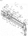
- Shuttle conveyance device 62 includes (a) two arm units, 100a and 100b, (b) moving body 102 that is provided between the two arm units 100a and 100b, (d) shuttle horizontal moving device 104, (e) arm rotating device 108, (f) stopping devices 110a and 110b (refer to Fig. 3 ), and the like.
- Each of the two arm units 100a and 100b and moving body 102 are each able to be connected and disconnected, and shuttle 112 is configured by moving body 102 and at least one of the arm units 100a and 100b which are connected to moving body 102.
- Shuttle horizontal moving device 104 moves shuttle 112 horizontally in a linear manner in the x direction and includes (a) one shuttle motor 122 (refer to Fig. 3 ) as a horizontal movement driving source that is able to rotate in both forward and reverse directions, (b) shuttle guide 124 that extends parallel to guide 50, (c) drive transfer apparatus 126 that converts the rotation of shuttle motor 122 into linear movement and that transfers the drive force of shuttle motor 122 to shuttle 112, and the like.
- Drive transfer apparatus 126 includes (x) multiple pulleys 130 that are provided on the main body of board conveyance device 14 such as on guide 50 so as to be able to rotate (one of the pulleys is included in Figs 4 and 6 ), (y) shuttle conveyance belt 132 that is wound around the output shaft of shuttle motor 122 and the multiple pulleys 130, (z) slider 134 that engages with shuttle conveyance belt 132 so that relative movement is not possible and that engages with shuttle guide 124 so that relative movement is possible, and the like.
- Arm rotating device 108 rotates arms 136a and 136b of arm units 100a and 100b and includes (a) one rotation cylinder (air cylinder) 140 as the rotation driving source, (b) rack and pinion mechanism 144 that converts the horizontal movement of movable member (piston rod) 142 of rotation cylinder 140 in the z direction to rotational movement, (c) spline shaft 146 that is the output shaft of rack and pinion mechanism 144 and that extends parallel to guide 50, and the like.
- movement of movable member 142 is controlled by controlling the high-pressure air supply state via control of electromagnetic valve 148 (refer to Figs. 10 ).
- Spline shaft 146 is rotated in direction R1 when movable member 142 is moved in direction z1 and is rotated in direction R2 when movable member 142 is moved in direction z2.
- Spline nuts 150a and 150b fit together in spline shaft 146 so as to be able to rotate integrally and so that relative movement is possible in the x direction.
- Moving body 102 includes slider 134 and spline nuts 150a and 150b, and is moved using shuttle horizontal moving device 104 and arm rotating device 108.
- Arm units 100a and 100b are moved with the movement of moving body 102 when in a state connected to moving body 102, and are not moved even when moving body 102 is moved when in a state disconnected from moving body 102. Due to this, moving body 102 has a function as one constituent element of the driving transmission section that transfers drive of shuttle motor 122 and rotation cylinder 140 to arm units 100a and 100b.
- the two arm units 100a and 100b are linked to each other in a state in which the two arm units 100a and 100b are connected to moving body 102. Due to this, moving body 102 also has a function as a linking body that links the two arm units 100a and 100b.
- Spline nuts 150a and 150b are held by nut holding sections 152a and 152b so as to be able to rotate integrally, and nut holding sections 152a and 152b are held at both end portions of slider 134 in the x direction so that relative movement is possible around the x-axis and so as to be able to move integrally in the x direction.
- Nut holding sections 152a and 152b form shapes with steps where there is a large diameter section and a small diameter section, the sides where the nut holding sections 152a and 152b oppose each other are set as large diameter sections 153a and 153b, and the arm unit sides of nut holding sections 152a and 152b are set as small diameter sections 154a and 154b.
- Spline nuts 150a and 150b each fit together in a fixed manner in the large diameter sections 153a and 153b.
- Unit rotating bodies 160a and 160b of arm units 100a and 100b each fit together in the small diameter sections 154a and 154b so as to be able to rotate integrally.
- keys 162a and 162b provided for unit rotating bodies 160a and 160b may be engaged with key grooves 156a and 156b formed in the outer peripheral surface of the small diameter sections 154a and 154b (156a and 162a are shown in Figs. 7 ).
- Connection recessed sections 164a and 164b which each extend in a direction that intersects with the x direction, are provided in end portions of the large diameter sections 153a and 153b on the small diameter section sides and are used in connection to arm units 100a and 100b.
- grooves 163a and 163b with an annular shape where the tangent is orthogonal to the x direction are formed in each of the end portions of the large diameter sections 153a and 153b on the opposite side from the small diameter sections 154a and 154b.
- Protruding sections 165a and 165b that each protrude in the z direction are provided on both end portions of slider 134 in the x direction.
- Nut holding sections 152a and 152b are held in slider 134 in a state in which protruding portions 165a and 165b engage with grooves 163a and 163b with the annular shape, in detail, in a state in which both side surfaces of protruding sections 165a and 165b face the wall portions of grooves 163a and 163b with the annular shape in the x direction. Due to this, nut holding sections 152a and 152b are able to move with movement of slider 134 in the x direction. In addition, movement of nut holding sections 152a and 152b in the x direction that accompanies rotation is favorably prevented by guiding rotation of nut holding sections 152a and 152b around the X-axis.
- the two arm units 100a and 100b form shapes that are symmetrical to each other with respect to the z-axis and have the same structures.
- Arm unit 100a will be described below; for arm unit 100b, in the drawings, the subscript b is given to the same numbers as the corresponding members of arm unit 100a; however, descriptions of arm unit 100b are omitted.
- Arm unit 100a includes arm 136a and arm holding section 166a that holds arm 136a.
- Arm 136a includes main body section 170a that generally extends in the x direction and is held on arm holding section 166a at the base portion, and claw 172a as the engaging section that is provided at a tip end portion that protrudes in the y direction to the opposite side from the base portion of main body section 170a.
- Claw 172a protrudes downward from main body section 170a and is able to engage with board P.
- the spacing L0 between claws 172a and 172b becomes larger since arms 136a and 136b each extend in directions so as to disengage from moving body 102 in a state in which the two arm units 100a and 100b are connected to moving body 102.
- the spacing L0 is substantially the same length as the length of rails 92p and 92q of board holding section 60.
- claw 172a is positioned on the downstream side end portion of shuttle 112 in a case where board P is conveyed in direction x1 and is positioned on the upstream side end portion of shuttle 112 in a case where board P is conveyed in direction x2. For this reason, claw 172a is applied to cases where board P is conveyed in direction x2.
- Arm holding section 166a includes each of holding section main body 174a and unit rotating body 160a.
- Unit rotating body 160a is held on holding section main body 174a so that relative movement around the x-axis is possible and arm 136a is held with respect to holding section main body 174a so that rotation is possible via link mechanism 178a (refer to Figs. 7 ).
- Holding section main body 174a includes engaging section 180a for shuttle guide 124, is not able to rotate, and is able to move horizontally in a linear manner in the x direction.
- Through-hole 182a that extends in the x direction is formed in a central portion of unit rotating body 160a and is in a state in which the small diameter section 154a of nut holding section 152a is inserted into through-hole 182a so as to be able to be inserted and removed.
- Lever 186a is held on the outer side of unit rotating body 160a so as to be able to rotate around rotation shaft 188a that extends in the y direction.
- the length of lever 186a in the x direction is longer than unit rotating body 160a and protrudes from both sides of unit rotating body 160a in the x direction.
- connection claw 190a is provided on the surface on the inner peripheral side of the end portion of lever 186a on the moving body side to protrude toward the inner peripheral side
- inclined portion 192a is provided on the surface on the outer peripheral side of the end portion of lever 186a on the opposite side from moving body 102 (the end portion on the stopping device side) .
- inclined portion 192a is inclined in the peripheral direction of unit rotating body 160a with an orientation so that the thickness increases (the outer surface protrudes to the outer peripheral side) from the front to the rear in the R1 direction.
- Lever 186a is able to rotate between a connection position where connection claw 190a engages with connection recessed section 164a of nut holding section 152a of moving body 102 and a disengaged position where connection claw 190a is disengaged from connection recessed section 164a and is biased toward the connection position by spring 196a that is provided on rotation shaft 188a.
- rotation engaging protruding section 200a with an arc shape that protrudes in the x direction is provided on an end portion of through-hole 182a on unit rotating body 160a on the stopping device side.
- Engagement claw 202a ⁇ refer to Figs. 7 , 8 ( 3 ) and 8 (4) ⁇ with an arc shape that protrudes to the inner peripheral side is provided on a tip end portion of rotation engaging protruding section 200a.
- link mechanism 178a includes (1) first rod 178ap that is linked to unit rotating body 160a such that relative rotation is possible, (2) second rod 178aq that is linked to holding section main body 174a such that relative rotation is possible, (3) third rod 178ar that is linked to first rod 178ap and second rod 178aq such that relative rotation is possible and that holds arm 136a, (4) spring 178as that imparts an elastic force onto second rod 178aq toward holding section main body 174a, (5) cam 178at that is provided on holding section main body 174a and that guides movement of first rod 178ap, and the like.
- Arm 136a is movable using link mechanism 178a between an operable position where it is possible for claw 172a to engage with board P that is on conveyance belts 74p, 74q, 86p, and 86q or rails 92p and 92q as shown in Fig. 7(a) and a retraction position where claw 172a is disengaged from board P as shown in Fig. 7(c) .
- Stopping devices 110a and 110b switch claws 172a and 172b between a state in which claws 172a and 172b are able to convey board P and a stopping state, and maintain the stopping state.
- the stopping state is a state of not moving horizontally in a linear manner even when shuttle motor 122 is in an operational state and of not rotating even when spline shaft 146 is rotating, and is able to be also be referred to as a stationary state.
- Stopping devices 110a and 110b are provided at positions which are outside the range of movement of shuttle 112 during conveyance of board P, in the present embodiment, on both end portions of spline shaft 146, and also have a function as stoppers.
- stopping devices 110a and 110b are symmetrical with respect to the z-axis and have the same structure, stopping device 110a will be described below and description of stopping device 110b will be omitted.
- stopping device 110a is provided on the main body of board conveyance device 14 (on guide 50 or the like) in a fixed manner and includes (a) main body 210a, (b) engaging section 212a that is generally formed in a cylindrical shape and provided on the outer periphery of spline shaft 146, (c) plate 214a as a lever rotating section that is provided on main body 210a to protrude in the x direction above engaging section 212a, and the like.
- Annular recessed section 216a with generally an annular shape is provided at an intermediate portion of engaging section 212a in the axial direction and cutout 218a that extends in the axial direction is provided across annular recessed section 216a.
- Length (the size of spacing) d1 of cutout 218a in the circumferential direction is set to be slightly larger than length d2 ⁇ refer to Fag. 7(c) ⁇ of engagement claw 202a of rotation engaging protruding section 200a in the circumferential direction (d1 > d2) and claw 202a is able to be engaged with cutout 212a.
- Control device 250 formed mainly of a computer, is provided in the electronic component assembly device. Control device 250 is connected to shuttle position sensor 252, arm rotation position sensor 254, and the like and is connected to shuttle motor 122, electromagnetic valve 148, and the like.
- Shuttle position sensor 252 detects the position of shuttle 122 in the x direction and detects whether shuttle 122 has reached an end position that is set in advance.
- Arm rotation position sensor 254 detects the position of movable member 142 of rotation cylinder 140 in the z direction and detects whether arms 136a and 136b are at the operable position or the retraction position.
- Shuttle conveyance device 62 is normally in a state in which each of the arm units 100a and 100b (the claws 172a and 172b) are connected to moving body 102, that is, in a state in which the two arm units 100a and 100b are linked via moving body 102.
- the two claws 172a and 172b are moved horizontally (simultaneously) in an integrated manner and the two arms 136a and 136b are integrally rotated.
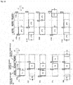
- two substrates are simultaneously conveyed using the two claws 172a and 172b in a case where a length L of board P in the x direction is smaller than a spacing L0 between the two claws 172a and 172b.
- the predetermined position above conveyance belts 74p and 74q on first conveyance device 56 is set as the standby position
- the predetermined position above rails 92p and 92q of board holding section 60 is set as the mounting position (insertion position or working position)
- the predetermined position above conveyance belts 84p and 84q on second conveyance device 58 is set as the discharge position.
- Board P is conveyed from the standby position to the mounting position and from the mounting position to the discharge position.
- T1 A board P1 that is conveyed to the standby position is moved in the x1 direction by being pushed from behind by claw 172b.
- T2 When the board P1 is moved to the mounting position, the two arms 136a and 136b are rotated to the retraction position and are moved horizontally to the standby position (return in the x2 direction). Work such as insertion of lead components, cutting of lead wires, or clinching is performed on the board P1 in a state in which the board P1 is clamped using rails 92p and 92q and clampers 94p and 94q.
- T3 When the work with respect to the board P1 is completed, the clamping is released.
- a board P2 which is introduced to the standby position is moved in the x1 direction by being pushed by claw 172b.
- claw 172a abuts with the board P1
- claws 172a and 172b simultaneously move the boards P1 and P2 in the x1 direction.
- the board P2 is moved to the mounting position and the board P1 is moved to the discharge position.
- the board P1 is discharged using second conveyance device 58, which is on the OUT side, and a subsequent board P3 is introduced to the standby position.
- T3) to (T5) are repeatedly performed hereinafter.
- conveyance belts 74p, 74q, 84p, and 84q of first conveyance device 56 and second conveyance device 58 are driven. Due to this, prevention of friction between conveyance belts 74p, 74q, 84p, and 84q, reduction in the load of claws 172a and 172b and arms 136a and 136b, an increase in the speed of board conveyance, and the like are achieved.
- claw 172a is in the stopping state in a case in which the length L of the board P is larger than spacing L0.
- One board P is conveyed in the x1 direction by claw 172b; operations in this case will be described based on Fig. 11(b) .
- (T11) Board P*1 that reaches the standby position is moved to the mounting position by being pushed from behind by claw 172b.
- (T12) When the work on board P*1 is completed, (T13) claw 172b moves the board P*1 to the discharge position.
- (T14) Arm 136b is rotated to the retraction position and is moved horizontally to the standby position.
- (T15) Arm 136b is rotated to the operable position and claw 172b moves a subsequent board P*2 that is introduced to the standby position to the mounting position while pushing from behind.
- the board P*1 that is at the discharge position is discharged using OUT conveyance device 58.
- (T13) to (T15) are repeatedly performed hereinafter.
- the time period for loading in this case is the sum (t*1 + t*2) of time period t*1 for movement from the standby position to the mounting position and time period t*2 for movement from the mounting position to the discharge position.
- one claw 172 which is determined based on the conveyance direction of the board P, out of claws 172a and 172b is selectively set to the stopping state.
- Claw 172a is in the stopping state in a case where the conveyance direction is x1 and claw 172b is in the stopping state in a case where the conveyance direction is x2.
- claw 172a is automatically set to the stopping state in a case where the length L of the conveyed board P is larger than spacing L0.
- Claw 172a is set to the stopping state by controlling shuttle horizontal moving device 104 and arm rotating device 106 in a case where it is determined that the length L of the board P is larger than spacing L0 based on information obtained from a production program that relates to the size of the conveyed board P.
- An engaging section stopping program represented by the flowchart in Fig. 10 is executed by control device 250.
- step 1 (hereinafter abbreviated to S1 with the same also applying to the other steps), information that relates to substrate size is read out, and it is determined whether the length L of the board P is a size which is equal to or less than spacing L0 in S2. In a case where the length L of the board P is equal to or less than L0, it is determined whether there is a claw which is in the stopping state (whether claw 172a is in the stopping state) in S3. There are no changes in a case where claw 172a is in a state in which conveyance is possible. In contrast to this, in a case where the length L of the board P is greater than L0, the determination in S2 is NO and it is determined whether claw 172a is in the stopping state in S4. In a case where claw 172a is not in the stopping state, claw 172a is automatically set to the stopping state in S5.
- Claw 172a is set to the stopping state by disconnecting the one arm unit 100a from a state in which the two arm units 100a and 100b are connected to moving body 102; operations in this case will be described based on Figs. 8 and 9 .
- arm holding section 166a remains in a state of being held by engaging section 212a of stopping device 110a without change. Since the small diameter section 154a of nut holding section 154a does not fit together with arm holding section 166a, unit rotating body 160a does not rotate even if spline shaft 146 rotates and there is no movement in the x direction even in a state in which shuttle motor 122 is in an operational state. Arm holding section 166a is in a stationary state and claw 172a is held in the stopping state. Furthermore, the phase of arm holding section 166a is held at the retraction position of arm 136a due to the elastic force of spring 178as, the stopper structure of link mechanism 178a, the weight of arm 136a, and the like. The phase and the position of arm holding section 166a in the axial direction are maintained in stopping device 110a without change from the state in (4).
- claw 172b is selected out of the two claws 172a and 172b and is set to the stopping state using stopping device 110b. Operation of shuttle motor 122 and rotation cylinder 140 are substantially the same as the case where claw 172a is set in the stopping state.
- the selective stopping device is configured in the embodiment above using stopping devices 110a and 110b, shuttle motor 122, electromagnetic valve 148, rotation cylinder 140, and parts in control device 250 for storing the engaging section stopping program and parts in control device 250 for executing the engaging section stopping program, which is represented by the flowchart in Fig. 10 , and the like.
- the selective stopping device is also a selective movement stopping section, a selective rotation stopping section, and a selective horizontal movement stopping section.
- the holding section disconnecting section is configured using lever rotating sections 214a and 214b
- the rotating body is configured using spline nuts 150a and 150b, nut holding sections 152a and 152b, and the like
- the engaging section holding section is configured using arm holding sections 166a and 166b and the like.
- the rotation actuator is configured using spline shaft 146 and the like
- the horizontal movement actuator is configured using shuttle conveyance belt 132 and the like.
- shuttle horizontal moving device 106 and arm rotating device 108 which is the engaging section rotating device, are moving devices, and the board conveyance device in the present embodiment includes these two moving devices.
- the board conveyance device is able to switch between a first conveyance state in which it is possible to convey two sheets (the first set number of sheets) of boards using the two (the first set number of units) claws 172a and 172b and a second conveyance state in which it is possible to convey one sheet (the second set number of sheets) of board using either one (the second set number of units) out of the claws 172a and 172b, and the selective stopping device described above also functions as the conveyance state switching device.
- both stopping devices 110a and 110b are provided at both end portions of shuttle conveyance device 62. Note that, it is not essential that both stopping devices 110a and 110b are provided and it is sufficient if only one is provided in a case where the conveyance direction is determined in advance.
- the device at the mounting position for the board P is not limited to a device for cutting or clinching and it is possible for the invention to be applied to a device which performs soldering and the like, and it is possible to be widely applied to component assembly devices.
Landscapes
- Engineering & Computer Science (AREA)
- Manufacturing & Machinery (AREA)
- Microelectronics & Electronic Packaging (AREA)
- Supply And Installment Of Electrical Components (AREA)
- Specific Conveyance Elements (AREA)
Applications Claiming Priority (1)
| Application Number | Priority Date | Filing Date | Title |
|---|---|---|---|
| PCT/JP2014/057814 WO2015140995A1 (fr) | 2014-03-20 | 2014-03-20 | Appareil de support de carte |
Publications (3)
| Publication Number | Publication Date |
|---|---|
| EP3122165A1 true EP3122165A1 (fr) | 2017-01-25 |
| EP3122165A4 EP3122165A4 (fr) | 2017-11-01 |
| EP3122165B1 EP3122165B1 (fr) | 2021-05-12 |
Family
ID=54143997
Family Applications (1)
| Application Number | Title | Priority Date | Filing Date |
|---|---|---|---|
| EP14885944.0A Active EP3122165B1 (fr) | 2014-03-20 | 2014-03-20 | Appareil de support de carte |
Country Status (5)
| Country | Link |
|---|---|
| US (1) | US9999168B2 (fr) |
| EP (1) | EP3122165B1 (fr) |
| JP (1) | JP6326130B2 (fr) |
| CN (1) | CN106105415B (fr) |
| WO (1) | WO2015140995A1 (fr) |
Cited By (1)
| Publication number | Priority date | Publication date | Assignee | Title |
|---|---|---|---|---|
| US20170099750A1 (en) * | 2014-03-20 | 2017-04-06 | Fuji Machine Mfg. Co., Ltd. | Board conveyance device |
Families Citing this family (3)
| Publication number | Priority date | Publication date | Assignee | Title |
|---|---|---|---|---|
| JP6824102B2 (ja) * | 2017-04-24 | 2021-02-03 | 株式会社ミツトヨ | ベルト駆動による軸方向移動装置 |
| JP2019176115A (ja) * | 2018-03-30 | 2019-10-10 | 東レエンジニアリング株式会社 | 基板搬送装置 |
| CN109366241B (zh) * | 2018-11-20 | 2024-01-26 | 广州赛志系统科技有限公司 | 智能柔性封边线规方系统 |
Family Cites Families (29)
| Publication number | Priority date | Publication date | Assignee | Title |
|---|---|---|---|---|
| JPH0680937B2 (ja) | 1984-12-05 | 1994-10-12 | 松下電器産業株式会社 | 基板搬送装置 |
| JPH062995Y2 (ja) * | 1986-02-21 | 1994-01-26 | マミヤ・オーピー株式会社 | 基板給送装置 |
| JPH0696407B2 (ja) * | 1986-04-23 | 1994-11-30 | 新明和工業株式会社 | 可動体の選択作動装置 |
| JPH02229499A (ja) | 1989-03-02 | 1990-09-12 | Sanyo Electric Co Ltd | 基板搬送装置 |
| JPH04299898A (ja) | 1991-03-28 | 1992-10-23 | Matsushita Electric Ind Co Ltd | プリント基板搬送装置 |
| JPH05178441A (ja) * | 1991-11-28 | 1993-07-20 | Komatsu Giken Kk | プリント基板の搬送装置 |
| JPH066084A (ja) * | 1992-06-19 | 1994-01-14 | Olympus Optical Co Ltd | 電子部品自動実装機 |
| JPH06191610A (ja) * | 1992-12-28 | 1994-07-12 | Juki Corp | 部品供給装置 |
| JP3227881B2 (ja) * | 1993-03-31 | 2001-11-12 | ソニー株式会社 | プリント配線基板搬送装置及び搬送方法 |
| JPH0878882A (ja) * | 1994-09-02 | 1996-03-22 | Fuji Mach Mfg Co Ltd | 対回路基板トランスファ作業装置 |
| US6088911A (en) * | 1995-12-28 | 2000-07-18 | Fuji Machine Mfg. Co., Ltd. | Electronic component transferring apparatus |
| JPH09260896A (ja) * | 1996-03-19 | 1997-10-03 | Matsushita Electric Ind Co Ltd | 回路基板搬送装置 |
| JPH1034456A (ja) * | 1996-07-24 | 1998-02-10 | Fuji Mach Mfg Co Ltd | 電子部品供給装置 |
| US6073342A (en) * | 1996-11-27 | 2000-06-13 | Fuji Machine Mfg., Co., Ltd. | Circuit-substrate-related-operation performing system |
| JPH11163000A (ja) * | 1997-12-02 | 1999-06-18 | Mitsubishi Electric Corp | リードフレーム移送装置 |
| ATE223639T1 (de) * | 1998-05-04 | 2002-09-15 | Vantico Ag | Vorrichtung zum transportieren dünner platten, insbesondere leiterplatten |
| JP2003188517A (ja) * | 2001-12-18 | 2003-07-04 | Senju Metal Ind Co Ltd | プリント基板の部分はんだ付け方法およびその装置 |
| JP2004297040A (ja) * | 2003-03-12 | 2004-10-21 | Seiko Epson Corp | 移載装置、搬送装置及び移載方法 |
| EP2043420B1 (fr) | 2006-06-29 | 2016-04-27 | Yamaha Motor Co., Ltd. | Appareil de montage en surface |
| JP4819601B2 (ja) * | 2006-06-30 | 2011-11-24 | ヤマハ発動機株式会社 | 表面実装機 |
| KR101138705B1 (ko) * | 2006-10-24 | 2012-04-19 | 삼성테크윈 주식회사 | 기판이송장치 |
| JP4833103B2 (ja) * | 2007-02-05 | 2011-12-07 | ヤマハ発動機株式会社 | 部品実装機 |
| JP5470770B2 (ja) * | 2008-08-07 | 2014-04-16 | シンフォニアテクノロジー株式会社 | 真空処理装置 |
| WO2010103829A1 (fr) * | 2009-03-11 | 2010-09-16 | パナソニック株式会社 | Système et procédé relatifs au processus de transfert de substrat, et appareil et procédé de montage de composant |
| JP5597050B2 (ja) * | 2010-07-15 | 2014-10-01 | 富士機械製造株式会社 | 基板停止位置制御方法および装置、ならびに基板装着位置制御方法 |
| US8695786B2 (en) * | 2010-12-07 | 2014-04-15 | Interroll Holding Ag | Singulated release for zoned conveyor systems |
| CN105144862B (zh) * | 2013-03-14 | 2018-10-09 | 株式会社富士 | 元件安装机的生产管理系统 |
| EP3088128B1 (fr) * | 2013-12-27 | 2019-08-07 | FUJI Corporation | Système d'alimentation en composants |
| US9999168B2 (en) * | 2014-03-20 | 2018-06-12 | Fuji Machine Mfg. Co., Ltd. | Board conveyance device |
-
2014
- 2014-03-20 US US15/127,213 patent/US9999168B2/en active Active
- 2014-03-20 EP EP14885944.0A patent/EP3122165B1/fr active Active
- 2014-03-20 WO PCT/JP2014/057814 patent/WO2015140995A1/fr not_active Ceased
- 2014-03-20 CN CN201480077283.8A patent/CN106105415B/zh active Active
- 2014-03-20 JP JP2016508423A patent/JP6326130B2/ja active Active
Cited By (2)
| Publication number | Priority date | Publication date | Assignee | Title |
|---|---|---|---|---|
| US20170099750A1 (en) * | 2014-03-20 | 2017-04-06 | Fuji Machine Mfg. Co., Ltd. | Board conveyance device |
| US9999168B2 (en) * | 2014-03-20 | 2018-06-12 | Fuji Machine Mfg. Co., Ltd. | Board conveyance device |
Also Published As
| Publication number | Publication date |
|---|---|
| JP6326130B2 (ja) | 2018-05-16 |
| JPWO2015140995A1 (ja) | 2017-04-06 |
| US9999168B2 (en) | 2018-06-12 |
| CN106105415A (zh) | 2016-11-09 |
| WO2015140995A1 (fr) | 2015-09-24 |
| EP3122165B1 (fr) | 2021-05-12 |
| CN106105415B (zh) | 2019-02-26 |
| EP3122165A4 (fr) | 2017-11-01 |
| US20170099750A1 (en) | 2017-04-06 |
Similar Documents
| Publication | Publication Date | Title |
|---|---|---|
| EP3122165B1 (fr) | Appareil de support de carte | |
| EP3625003B1 (fr) | Préhenseur de pièces | |
| WO2013042544A1 (fr) | Élément de montage d'un composant de circuit électronique | |
| US9913419B2 (en) | Feeder | |
| EP3151649A1 (fr) | Machine de montage de composants | |
| EP3043630B1 (fr) | Système de traitement pour substrat | |
| JP2019010723A (ja) | ロボットハンド、ロボット装置、ロボットハンドの制御方法 | |
| EP3471527B1 (fr) | Dispositif de montage de composant électronique et procédé de séparation de composant électronique | |
| WO2015052753A1 (fr) | Mandrin et dispositif de montage de pièces | |
| CN104999469A (zh) | 一种机械手以及移载机构 | |
| US8726770B2 (en) | Machine tool | |
| US10759620B2 (en) | Tape feeder holding device | |
| CN115723367A (zh) | 用于抓持环形轮胎部件的抓持器、抓持器工位和方法 | |
| KR101520968B1 (ko) | 공구 교환의 다중 구동 장치 | |
| JP7144582B2 (ja) | 搬送ハンドのセット及び搬送ロボット | |
| KR101877836B1 (ko) | 자재 생산 설비 내에서의 자재 회전을 위한 컨베이어 장치 | |
| JPWO2005081611A1 (ja) | 支持ピン把持装置および基板支持装置 | |
| JP2005118930A (ja) | 加工セル | |
| US10951092B2 (en) | Transport system, carriage, positioning apparatus, processing system, and positioning method | |
| US20210245222A1 (en) | Divided tool attachment method and press brake | |
| JP4900210B2 (ja) | 汎用ハンドリング治具 | |
| JP2012096297A (ja) | ねじ締め装置及びねじ締め方法 | |
| TWI564985B (zh) | Electronic components for the unit and its application of the operating equipment | |
| CN121514948A (zh) | 一种具有柔性补偿功能的换刀机械手爪 | |
| CN113170608B (zh) | 作业头以及作业机 |
Legal Events
| Date | Code | Title | Description |
|---|---|---|---|
| PUAI | Public reference made under article 153(3) epc to a published international application that has entered the european phase |
Free format text: ORIGINAL CODE: 0009012 |
|
| STAA | Information on the status of an ep patent application or granted ep patent |
Free format text: STATUS: REQUEST FOR EXAMINATION WAS MADE |
|
| 17P | Request for examination filed |
Effective date: 20160920 |
|
| AK | Designated contracting states |
Kind code of ref document: A1 Designated state(s): AL AT BE BG CH CY CZ DE DK EE ES FI FR GB GR HR HU IE IS IT LI LT LU LV MC MK MT NL NO PL PT RO RS SE SI SK SM TR |
|
| AX | Request for extension of the european patent |
Extension state: BA ME |
|
| DAX | Request for extension of the european patent (deleted) | ||
| A4 | Supplementary search report drawn up and despatched |
Effective date: 20170929 |
|
| RIC1 | Information provided on ipc code assigned before grant |
Ipc: B65G 47/82 20060101ALI20170925BHEP Ipc: H05K 13/00 20060101ALI20170925BHEP Ipc: H05K 13/02 20060101AFI20170925BHEP |
|
| RAP1 | Party data changed (applicant data changed or rights of an application transferred) |
Owner name: FUJI CORPORATION |
|
| RIN1 | Information on inventor provided before grant (corrected) |
Inventor name: OTSUBO, SATORU Inventor name: YAMAMURO, JUNICHI |
|
| STAA | Information on the status of an ep patent application or granted ep patent |
Free format text: STATUS: EXAMINATION IS IN PROGRESS |
|
| 17Q | First examination report despatched |
Effective date: 20200519 |
|
| GRAJ | Information related to disapproval of communication of intention to grant by the applicant or resumption of examination proceedings by the epo deleted |
Free format text: ORIGINAL CODE: EPIDOSDIGR1 |
|
| GRAP | Despatch of communication of intention to grant a patent |
Free format text: ORIGINAL CODE: EPIDOSNIGR1 |
|
| GRAP | Despatch of communication of intention to grant a patent |
Free format text: ORIGINAL CODE: EPIDOSNIGR1 |
|
| STAA | Information on the status of an ep patent application or granted ep patent |
Free format text: STATUS: GRANT OF PATENT IS INTENDED |
|
| INTG | Intention to grant announced |
Effective date: 20201210 |
|
| GRAS | Grant fee paid |
Free format text: ORIGINAL CODE: EPIDOSNIGR3 |
|
| GRAA | (expected) grant |
Free format text: ORIGINAL CODE: 0009210 |
|
| STAA | Information on the status of an ep patent application or granted ep patent |
Free format text: STATUS: THE PATENT HAS BEEN GRANTED |
|
| AK | Designated contracting states |
Kind code of ref document: B1 Designated state(s): AL AT BE BG CH CY CZ DE DK EE ES FI FR GB GR HR HU IE IS IT LI LT LU LV MC MK MT NL NO PL PT RO RS SE SI SK SM TR |
|
| REG | Reference to a national code |
Ref country code: GB Ref legal event code: FG4D |
|
| REG | Reference to a national code |
Ref country code: CH Ref legal event code: EP |
|
| REG | Reference to a national code |
Ref country code: DE Ref legal event code: R096 Ref document number: 602014077467 Country of ref document: DE |
|
| REG | Reference to a national code |
Ref country code: IE Ref legal event code: FG4D |
|
| REG | Reference to a national code |
Ref country code: AT Ref legal event code: REF Ref document number: 1393075 Country of ref document: AT Kind code of ref document: T Effective date: 20210615 |
|
| REG | Reference to a national code |
Ref country code: LT Ref legal event code: MG9D |
|
| REG | Reference to a national code |
Ref country code: AT Ref legal event code: MK05 Ref document number: 1393075 Country of ref document: AT Kind code of ref document: T Effective date: 20210512 |
|
| REG | Reference to a national code |
Ref country code: NL Ref legal event code: MP Effective date: 20210512 |
|
| PG25 | Lapsed in a contracting state [announced via postgrant information from national office to epo] |
Ref country code: HR Free format text: LAPSE BECAUSE OF FAILURE TO SUBMIT A TRANSLATION OF THE DESCRIPTION OR TO PAY THE FEE WITHIN THE PRESCRIBED TIME-LIMIT Effective date: 20210512 Ref country code: LT Free format text: LAPSE BECAUSE OF FAILURE TO SUBMIT A TRANSLATION OF THE DESCRIPTION OR TO PAY THE FEE WITHIN THE PRESCRIBED TIME-LIMIT Effective date: 20210512 Ref country code: FI Free format text: LAPSE BECAUSE OF FAILURE TO SUBMIT A TRANSLATION OF THE DESCRIPTION OR TO PAY THE FEE WITHIN THE PRESCRIBED TIME-LIMIT Effective date: 20210512 Ref country code: AT Free format text: LAPSE BECAUSE OF FAILURE TO SUBMIT A TRANSLATION OF THE DESCRIPTION OR TO PAY THE FEE WITHIN THE PRESCRIBED TIME-LIMIT Effective date: 20210512 Ref country code: BG Free format text: LAPSE BECAUSE OF FAILURE TO SUBMIT A TRANSLATION OF THE DESCRIPTION OR TO PAY THE FEE WITHIN THE PRESCRIBED TIME-LIMIT Effective date: 20210812 |
|
| PG25 | Lapsed in a contracting state [announced via postgrant information from national office to epo] |
Ref country code: ES Free format text: LAPSE BECAUSE OF FAILURE TO SUBMIT A TRANSLATION OF THE DESCRIPTION OR TO PAY THE FEE WITHIN THE PRESCRIBED TIME-LIMIT Effective date: 20210512 Ref country code: PT Free format text: LAPSE BECAUSE OF FAILURE TO SUBMIT A TRANSLATION OF THE DESCRIPTION OR TO PAY THE FEE WITHIN THE PRESCRIBED TIME-LIMIT Effective date: 20210913 Ref country code: NO Free format text: LAPSE BECAUSE OF FAILURE TO SUBMIT A TRANSLATION OF THE DESCRIPTION OR TO PAY THE FEE WITHIN THE PRESCRIBED TIME-LIMIT Effective date: 20210812 Ref country code: PL Free format text: LAPSE BECAUSE OF FAILURE TO SUBMIT A TRANSLATION OF THE DESCRIPTION OR TO PAY THE FEE WITHIN THE PRESCRIBED TIME-LIMIT Effective date: 20210512 Ref country code: SE Free format text: LAPSE BECAUSE OF FAILURE TO SUBMIT A TRANSLATION OF THE DESCRIPTION OR TO PAY THE FEE WITHIN THE PRESCRIBED TIME-LIMIT Effective date: 20210512 Ref country code: RS Free format text: LAPSE BECAUSE OF FAILURE TO SUBMIT A TRANSLATION OF THE DESCRIPTION OR TO PAY THE FEE WITHIN THE PRESCRIBED TIME-LIMIT Effective date: 20210512 Ref country code: IS Free format text: LAPSE BECAUSE OF FAILURE TO SUBMIT A TRANSLATION OF THE DESCRIPTION OR TO PAY THE FEE WITHIN THE PRESCRIBED TIME-LIMIT Effective date: 20210912 Ref country code: LV Free format text: LAPSE BECAUSE OF FAILURE TO SUBMIT A TRANSLATION OF THE DESCRIPTION OR TO PAY THE FEE WITHIN THE PRESCRIBED TIME-LIMIT Effective date: 20210512 Ref country code: GR Free format text: LAPSE BECAUSE OF FAILURE TO SUBMIT A TRANSLATION OF THE DESCRIPTION OR TO PAY THE FEE WITHIN THE PRESCRIBED TIME-LIMIT Effective date: 20210813 |
|
| PG25 | Lapsed in a contracting state [announced via postgrant information from national office to epo] |
Ref country code: NL Free format text: LAPSE BECAUSE OF FAILURE TO SUBMIT A TRANSLATION OF THE DESCRIPTION OR TO PAY THE FEE WITHIN THE PRESCRIBED TIME-LIMIT Effective date: 20210512 |
|
| PG25 | Lapsed in a contracting state [announced via postgrant information from national office to epo] |
Ref country code: EE Free format text: LAPSE BECAUSE OF FAILURE TO SUBMIT A TRANSLATION OF THE DESCRIPTION OR TO PAY THE FEE WITHIN THE PRESCRIBED TIME-LIMIT Effective date: 20210512 Ref country code: DK Free format text: LAPSE BECAUSE OF FAILURE TO SUBMIT A TRANSLATION OF THE DESCRIPTION OR TO PAY THE FEE WITHIN THE PRESCRIBED TIME-LIMIT Effective date: 20210512 Ref country code: CZ Free format text: LAPSE BECAUSE OF FAILURE TO SUBMIT A TRANSLATION OF THE DESCRIPTION OR TO PAY THE FEE WITHIN THE PRESCRIBED TIME-LIMIT Effective date: 20210512 Ref country code: SM Free format text: LAPSE BECAUSE OF FAILURE TO SUBMIT A TRANSLATION OF THE DESCRIPTION OR TO PAY THE FEE WITHIN THE PRESCRIBED TIME-LIMIT Effective date: 20210512 Ref country code: SK Free format text: LAPSE BECAUSE OF FAILURE TO SUBMIT A TRANSLATION OF THE DESCRIPTION OR TO PAY THE FEE WITHIN THE PRESCRIBED TIME-LIMIT Effective date: 20210512 Ref country code: RO Free format text: LAPSE BECAUSE OF FAILURE TO SUBMIT A TRANSLATION OF THE DESCRIPTION OR TO PAY THE FEE WITHIN THE PRESCRIBED TIME-LIMIT Effective date: 20210512 |
|
| REG | Reference to a national code |
Ref country code: DE Ref legal event code: R097 Ref document number: 602014077467 Country of ref document: DE |
|
| PLBE | No opposition filed within time limit |
Free format text: ORIGINAL CODE: 0009261 |
|
| STAA | Information on the status of an ep patent application or granted ep patent |
Free format text: STATUS: NO OPPOSITION FILED WITHIN TIME LIMIT |
|
| 26N | No opposition filed |
Effective date: 20220215 |
|
| PG25 | Lapsed in a contracting state [announced via postgrant information from national office to epo] |
Ref country code: IS Free format text: LAPSE BECAUSE OF FAILURE TO SUBMIT A TRANSLATION OF THE DESCRIPTION OR TO PAY THE FEE WITHIN THE PRESCRIBED TIME-LIMIT Effective date: 20210912 Ref country code: AL Free format text: LAPSE BECAUSE OF FAILURE TO SUBMIT A TRANSLATION OF THE DESCRIPTION OR TO PAY THE FEE WITHIN THE PRESCRIBED TIME-LIMIT Effective date: 20210512 |
|
| PG25 | Lapsed in a contracting state [announced via postgrant information from national office to epo] |
Ref country code: IT Free format text: LAPSE BECAUSE OF FAILURE TO SUBMIT A TRANSLATION OF THE DESCRIPTION OR TO PAY THE FEE WITHIN THE PRESCRIBED TIME-LIMIT Effective date: 20210512 |
|
| PG25 | Lapsed in a contracting state [announced via postgrant information from national office to epo] |
Ref country code: MC Free format text: LAPSE BECAUSE OF FAILURE TO SUBMIT A TRANSLATION OF THE DESCRIPTION OR TO PAY THE FEE WITHIN THE PRESCRIBED TIME-LIMIT Effective date: 20210512 |
|
| REG | Reference to a national code |
Ref country code: CH Ref legal event code: PL |
|
| GBPC | Gb: european patent ceased through non-payment of renewal fee |
Effective date: 20220320 |
|
| REG | Reference to a national code |
Ref country code: BE Ref legal event code: MM Effective date: 20220331 |
|
| PG25 | Lapsed in a contracting state [announced via postgrant information from national office to epo] |
Ref country code: LU Free format text: LAPSE BECAUSE OF NON-PAYMENT OF DUE FEES Effective date: 20220320 Ref country code: LI Free format text: LAPSE BECAUSE OF NON-PAYMENT OF DUE FEES Effective date: 20220331 Ref country code: IE Free format text: LAPSE BECAUSE OF NON-PAYMENT OF DUE FEES Effective date: 20220320 Ref country code: GB Free format text: LAPSE BECAUSE OF NON-PAYMENT OF DUE FEES Effective date: 20220320 Ref country code: FR Free format text: LAPSE BECAUSE OF NON-PAYMENT OF DUE FEES Effective date: 20220331 Ref country code: CH Free format text: LAPSE BECAUSE OF NON-PAYMENT OF DUE FEES Effective date: 20220331 |
|
| PG25 | Lapsed in a contracting state [announced via postgrant information from national office to epo] |
Ref country code: BE Free format text: LAPSE BECAUSE OF NON-PAYMENT OF DUE FEES Effective date: 20220331 |
|
| P01 | Opt-out of the competence of the unified patent court (upc) registered |
Effective date: 20230328 |
|
| PG25 | Lapsed in a contracting state [announced via postgrant information from national office to epo] |
Ref country code: HU Free format text: LAPSE BECAUSE OF FAILURE TO SUBMIT A TRANSLATION OF THE DESCRIPTION OR TO PAY THE FEE WITHIN THE PRESCRIBED TIME-LIMIT; INVALID AB INITIO Effective date: 20140320 |
|
| PG25 | Lapsed in a contracting state [announced via postgrant information from national office to epo] |
Ref country code: MK Free format text: LAPSE BECAUSE OF FAILURE TO SUBMIT A TRANSLATION OF THE DESCRIPTION OR TO PAY THE FEE WITHIN THE PRESCRIBED TIME-LIMIT Effective date: 20210512 Ref country code: CY Free format text: LAPSE BECAUSE OF FAILURE TO SUBMIT A TRANSLATION OF THE DESCRIPTION OR TO PAY THE FEE WITHIN THE PRESCRIBED TIME-LIMIT Effective date: 20210512 |
|
| PG25 | Lapsed in a contracting state [announced via postgrant information from national office to epo] |
Ref country code: MT Free format text: LAPSE BECAUSE OF FAILURE TO SUBMIT A TRANSLATION OF THE DESCRIPTION OR TO PAY THE FEE WITHIN THE PRESCRIBED TIME-LIMIT Effective date: 20210512 |
|
| PG25 | Lapsed in a contracting state [announced via postgrant information from national office to epo] |
Ref country code: TR Free format text: LAPSE BECAUSE OF FAILURE TO SUBMIT A TRANSLATION OF THE DESCRIPTION OR TO PAY THE FEE WITHIN THE PRESCRIBED TIME-LIMIT Effective date: 20210512 |
|
| PGFP | Annual fee paid to national office [announced via postgrant information from national office to epo] |
Ref country code: DE Payment date: 20260128 Year of fee payment: 13 |