EP3126104B1 - Führungssystem für versorgungsleitungen und roboter mit führungssystem - Google Patents
Führungssystem für versorgungsleitungen und roboter mit führungssystem Download PDFInfo
- Publication number
- EP3126104B1 EP3126104B1 EP15713168.1A EP15713168A EP3126104B1 EP 3126104 B1 EP3126104 B1 EP 3126104B1 EP 15713168 A EP15713168 A EP 15713168A EP 3126104 B1 EP3126104 B1 EP 3126104B1
- Authority
- EP
- European Patent Office
- Prior art keywords
- guide
- deflecting element
- belt
- rail
- guide system
- Prior art date
- Legal status (The legal status is an assumption and is not a legal conclusion. Google has not performed a legal analysis and makes no representation as to the accuracy of the status listed.)
- Active
Links
Images

Classifications
-
- B—PERFORMING OPERATIONS; TRANSPORTING
- B25—HAND TOOLS; PORTABLE POWER-DRIVEN TOOLS; MANIPULATORS
- B25J—MANIPULATORS; CHAMBERS PROVIDED WITH MANIPULATION DEVICES
- B25J19/00—Accessories fitted to manipulators, e.g. for monitoring, for viewing; Safety devices combined with or specially adapted for use in connection with manipulators
-
- B—PERFORMING OPERATIONS; TRANSPORTING
- B25—HAND TOOLS; PORTABLE POWER-DRIVEN TOOLS; MANIPULATORS
- B25J—MANIPULATORS; CHAMBERS PROVIDED WITH MANIPULATION DEVICES
- B25J19/00—Accessories fitted to manipulators, e.g. for monitoring, for viewing; Safety devices combined with or specially adapted for use in connection with manipulators
- B25J19/0025—Means for supplying energy to the end effector
-
- B—PERFORMING OPERATIONS; TRANSPORTING
- B25—HAND TOOLS; PORTABLE POWER-DRIVEN TOOLS; MANIPULATORS
- B25J—MANIPULATORS; CHAMBERS PROVIDED WITH MANIPULATION DEVICES
- B25J19/00—Accessories fitted to manipulators, e.g. for monitoring, for viewing; Safety devices combined with or specially adapted for use in connection with manipulators
- B25J19/0025—Means for supplying energy to the end effector
- B25J19/0029—Means for supplying energy to the end effector arranged within the different robot elements
-
- F—MECHANICAL ENGINEERING; LIGHTING; HEATING; WEAPONS; BLASTING
- F16—ENGINEERING ELEMENTS AND UNITS; GENERAL MEASURES FOR PRODUCING AND MAINTAINING EFFECTIVE FUNCTIONING OF MACHINES OR INSTALLATIONS; THERMAL INSULATION IN GENERAL
- F16L—PIPES; JOINTS OR FITTINGS FOR PIPES; SUPPORTS FOR PIPES, CABLES OR PROTECTIVE TUBING; MEANS FOR THERMAL INSULATION IN GENERAL
- F16L3/00—Supports for pipes, cables or protective tubing, e.g. hangers, holders, clamps, cleats, clips, brackets
- F16L3/01—Supports for pipes, cables or protective tubing, e.g. hangers, holders, clamps, cleats, clips, brackets for supporting or guiding the pipes, cables or protective tubing, between relatively movable points, e.g. movable channels
- F16L3/015—Supports for pipes, cables or protective tubing, e.g. hangers, holders, clamps, cleats, clips, brackets for supporting or guiding the pipes, cables or protective tubing, between relatively movable points, e.g. movable channels using articulated- or supple-guiding elements
-
- H—ELECTRICITY
- H02—GENERATION; CONVERSION OR DISTRIBUTION OF ELECTRIC POWER
- H02G—INSTALLATION OF ELECTRIC CABLES OR LINES, OR OF COMBINED OPTICAL AND ELECTRIC CABLES OR LINES
- H02G3/00—Installations of electric cables or lines or protective tubing therefor in or on buildings, equivalent structures or vehicles
- H02G3/02—Details
- H02G3/04—Protective tubing or conduits, e.g. cable ladders or cable troughs
- H02G3/0462—Tubings, i.e. having a closed section
- H02G3/0468—Corrugated
-
- H—ELECTRICITY
- H02—GENERATION; CONVERSION OR DISTRIBUTION OF ELECTRIC POWER
- H02G—INSTALLATION OF ELECTRIC CABLES OR LINES, OR OF COMBINED OPTICAL AND ELECTRIC CABLES OR LINES
- H02G11/00—Arrangements of electric cables or lines between relatively-movable parts
-
- Y—GENERAL TAGGING OF NEW TECHNOLOGICAL DEVELOPMENTS; GENERAL TAGGING OF CROSS-SECTIONAL TECHNOLOGIES SPANNING OVER SEVERAL SECTIONS OF THE IPC; TECHNICAL SUBJECTS COVERED BY FORMER USPC CROSS-REFERENCE ART COLLECTIONS [XRACs] AND DIGESTS
- Y10—TECHNICAL SUBJECTS COVERED BY FORMER USPC
- Y10S—TECHNICAL SUBJECTS COVERED BY FORMER USPC CROSS-REFERENCE ART COLLECTIONS [XRACs] AND DIGESTS
- Y10S901/00—Robots
- Y10S901/27—Arm part
- Y10S901/28—Joint
Definitions
- the invention relates to a guide system for supply lines for a handling device, in particular for a robot, having a guide base having a guide rail, guided by the guide base along a linear path deflecting element, which is arranged on a carriage which passes through the guide rail along the travel path is guided, and a chain, tubular or ribbon-like strand, in or on which the supply lines can be arranged, wherein the strand, forming a deflecting arc, is guided around the deflecting element and two subsequent to the ends of the Umlenkbogens dreams each with one at the Having a free end arranged connecting point, namely a first, stationary base to the guide base and a second, relative to the guide base movable connection point, and wherein the deflecting element by acting on the strand with the second connection point tensile force along the travel path against a Restoring force is moved from a retracted position to an extended position, wherein the restoring force can be generated by a arranged on or in the guide base restoring device.
- the invention further relates to a handling device, in particular robot, with such a guide system, wherein the guide base arranged on a first part of the handling device and the strand of the chain, tubular and ribbon-like strand connected to the first connection point with this part and the strand with the second connection point with a first part movable second Part of the handling device is connected.
- Such a guide system and handling device with such a guide system is from the DE 20 2011 004 786 U1 known.
- a pneumatic pressure cylinder is provided as a return device for the deflecting element designed as a deflection roller, which engages with its plunger on an armature in which the axis of the guide roller is mounted and which engages in a guide rail slidably.
- the restoring force for the deflection roller generating pneumatic pressure cylinder and the required power supply of the printing cylinder require a correspondingly dimensioned space on or in the handling device and are relatively expensive.
- a guide system for a cable in which the cable is guided by a guided by a guide base and movable against the restoring force of a restoring deflection element, wherein the return means comprises a resilient cable which is arranged adjacent to a retracted position of the deflection element on the guide base Deflection device is guided and subsequently has a first portion which is connected to the deflection element, and has a second portion which is connected to the guide base.
- the end of the first section of the elastic rope is attached to a roll-off protection of the deflection roller designed as a deflecting element.
- the deflection device known from this publication is arranged within the guide base formed as a guide rail.
- the return device which comprises the deflection device and the two sections of the elastic cable, extends over a relatively large area in the interior of the guide rail, so that the guide rail system enclosing the guide rail has a relatively large space occupies. Furthermore, the guide system is due to the necessary dimensioning of the guide base to a correspondingly high weight.
- the arrangement of the deflection in the guide rail requires some effort in the design of the guide rail and the insertion and optionally removal of the deflection.
- the present invention has for its object to provide a guide system with a return device, which requires a smaller space on or in the handling device, is less expensive and easier and therefore also for smaller handling equipment, especially robots, is suitable.
- the restoring device comprises at least one elastic cable or elastic band which is guided to a retracted to the retracted position of the deflecting element on the guide base deflecting device and subsequently has a first section, which is connected to the deflection element, and has a second portion which is connected to the guide base, wherein the end of the first portion of the at least one elastic rope or belt is attached to the carriage, and the deflection device is arranged on the end face of the guide rail in the direction of the travel path from the extended to the retracted position of the deflecting element, and has a housing which has an opening for the two sections of the at least one elastic band or rope on its end face facing the deflecting element.
- the dimensioning of the guide rail can be largely reduced to its guiding function for the deflection and the Guidance system for supply lines for a handling device are designed so that it occupies a relatively small space, has a relatively low weight and is technically relatively simple and therefore less expensive to implement. Due to these advantages, it is particularly suitable for smaller handling devices, in particular robots.
- the at least one elastic cable or elastic band having return device requires a relatively small space, so that the guide system according to the invention in areas of a handling device can be attached, for which the known system would not be suitable. It is therefore particularly applicable to smaller robots, also because of its relatively low weight. Furthermore, the reset device is technically relatively easy to implement and therefore less expensive.
- the rope or band made of natural or synthetic rubber preferably has a sheath which increases its abrasion resistance and / or lubricity.
- the sheath thus exerts a protective or sliding function on the elastic rope or band, which is guided during the process of the deflecting element to this and thereby exposed to friction.
- the sheathing may be a thin plastic layer, for example Teflon®, sprayed onto the rope or belt.
- a braid of the wear and / or lubricity of the rope or belt increasing plastic fibers is provided for the sheath, such as Fibers of polyethylene, Kevlar®, polyamides or aramids.
- the braid of such fibers is preferably formed so that it can stretch and contract in the longitudinal direction of the elastic rope or ribbon.
- the length of the rope or strap to be stretched in the process from the retracted position to the extended position of the deflection element is greater than the travel path. Since the elongation of the elastic rope or band thus extends over a greater length than that of the travel path, a relatively constant spring force of the rope or band over the travel of the deflection element is established.
- the second portion of the at least one elastic cord or band connected to the guide base preferably extends over at least the length of travel of the deflector between its retracted position and its extended position.
- the at least one elastic cord or band is arranged in the restoring device and connected to the deflecting element and the guide base in such a way that it has a predetermined tensile stress in the retracted position of the deflecting element.
- the restoring device can in particular have two elastic ropes or elastic bands.
- the deflection can limit the travel of the deflection in the retracted position with such an arrangement.
- the deflection device may have a roller, on the circumference of which the elastic cable or band rests and which is mounted in the housing.
- the second portion of the elastic cord or band extends in a groove or a laterally closed channel of the guide rail.
- the channel or the channel serve to protect and guide the extending between the deflection and the attachment point on the guide rail portion of the elastic rope or belt.
- the first portion of the elastic cord or band connected to the deflecting element may extend within the guide rail, its end region being connected to a region of the carriage extending through a slot into the interior of the guide rail.
- the slot may be closed to the outside by means of a roll which can be rolled up with the carriage or by a bellows or the like.
- a profile rail is used as a guide rail.
- the rail is preferably made of metal, in particular aluminum and can be easily adapted by cutting to the desired length of the travel of the deflection.
- it can also consist of a suitable plastic material, which in particular has good sliding properties.
- the housing can serve as a stop for the limitation of the travel of the carriage on the rail from the attracted position of the deflecting element in the retracted position.
- the profile rail has two in a preferred embodiment laterally projecting slide rails, wherein the carriage has in its lateral areas two housing parts for receiving the slide rails and connected to the two housing parts plate-shaped mounting member for fixing the deflecting element.
- the housing parts may be formed as a housing bearing with, for example, arranged therein plain bearings.
- the deflection element is designed as a deflection roller, on the circumference of the deflection of the supply lines containing strand is applied and whose axis is rotatably mounted on the carriage.
- the axis of the deflection roller is preferably arranged perpendicular to the axis of the roller designed as a deflection device for the elastic rope or band.
- the end of the second portion of the at least one elastic cord or belt may be secured to the end of the guide rail facing in the direction of travel from the retracted position to the extended position of the deflector.
- a web extending transversely to the guide rail and protruding on both sides may be arranged, at one end of which a holding device for the stationary support of the run of Having the supply lines containing strand with the first connection point and at the other end region a guide for the strand of the strand with the second connection point.
- a holding device a strand at the relevant point fixing retaining ring can be used.
- the guide the strand of the strand with the second connection point can be used as an annular sliding bushing, optionally with a pendulum bearing, be formed.
- the guide rail may have on its longitudinal side opposite the carriage support means which are arranged adjustable and lockable in the longitudinal direction of the guide rail.
- clamping shoes may be provided which engage in lateral grooves of the guide rail.
- the present invention further relates to a handling device, in particular robot, with one of the guide systems defined above, wherein the guide base is disposed on a first part of the handling device and the run of the chain, hose or ribbon-like strand connected to the first connection point with this part and the strand is connected to the second connection point with a first part movable second part of the handling device.
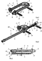
- Fig. 1 and 2 is an embodiment of a guide system for (not shown in the drawing) supply lines for a (not shown in the drawing) handling device, in particular for a robot, shown having a guide base 1, through which formed as a deflection roller deflecting element 2 along a linear travel path between a retracted position ( Fig. 1 ) and an extended position ( Fig. 2 ) can be performed.
- a guide base 1 through which formed as a deflection roller deflecting element 2 along a linear travel path between a retracted position ( Fig. 1 ) and an extended position ( Fig. 2 ) can be performed.
- To the deflecting element 2 of the deflection arc 3 of a chain-like strand 4 is guided, which has two subsequent to the deflection arc 3 runs 5 and 6.
- the strand 5 has at its free end a first, stationary to the guide base 1 connection point 7 and the strand 6 a second, relative to the guide base 1 movable connection point 8.
- the guide base 1 is formed as a profile rail. This consists of heartanodformatem aluminum and is adapted by cutting to length from a profile strand to the desired length of travel of the deflection element 2.
- the deflecting element 2 designed as a deflecting roller is rotatably mounted with its axis 10 in a carriage 11 which is guided on the profiled rail.
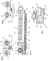
- the restoring device 9 has at least one elastic cable 12 which can be moved around one to the retracted position (FIG. Fig. 6 ) of the deflecting element adjacent to the guide base 1 arranged deflecting device 13 is guided and subsequently has a first portion 14 which is connected to the carriage of the deflection element 2 arranged thereon, and a second portion 15 which with the guide base 1 is connected.
- the fixation of the free end of the first portion 14 of the elastic rope 12 on the carriage 11 is in the Fig. 6 and 10 shown only schematically, as well as the fixation of the free end of the second portion 15 on the guide base 1.
- two elastic cables 12 are provided, the first portions 14 are connected to the carriage 11 and the second portions 15 to the guide base 1.
- the deflecting device 13 for the two elastic cables each have a roller 16, on the circumference of which the respective elastic cable rests.
- the two cables 12 are guided around the roller 16, so that the elastic cables 12 take place over their entire length, in particular also via their second sections 15. Therefore, a return force that is largely constant over the travel path of the deflection element 2 results.
- the two rollers 16 for the two elastic ropes 12 are separated by an intermediate disc 17.
- the two rollers 16 may be rotationally fixed on a common axis which is rotatably mounted in the intermediate disc 17, may be arranged.
- rollers 16 and the intermediate disk 17 are arranged in a housing 18.
- the slide 11 facing the end face of the housing 18 is open to carry out the two sections 14 and 15 of the elastic ropes 12.
- the housing 18 can continue as a stop for the limitation of the travel of the carriage 11 from the rail from the extended position of the deflecting element 2 serve in its retracted position.
- the two elastic ropes 12 are arranged and their length is dimensioned so that in the retracted position of the deflecting element 2, in which the carriage 11 may rest against the housing 18 of the deflecting device 13, a tensile stress on the carriage 11 and thus on the deflecting element 2 acts.
- the second portions 15 of the two elastic cables 12 are arranged in a laterally closed and extending over the entire length of the rail 19 channel.
- the two first sections 14 of the two elastic cables 12, however, are free between the housing 18 and the carriage 11 above the guide base 1.
- the profile rail has, as shown in the cross-sectional views of Fig. 5 and 9 shows, two laterally projecting slide rails 20.
- the carriage 11 has in its lateral areas two housing parts 21 for receiving the slide rails 20 and connected to the two housing parts 21 plate-shaped mounting member 22 to which the ends of the two first portions 14 of the elastic cables 12 are fixed and the axis 10 of the guide roller is stored for the chain-like strand 4.
- the housing parts 21 are designed as a housing bearing with slide bearings arranged therein.
- the free ends of the second portions 15 of the two elastic cables 12 are in the region of the end of the rail, which has in the direction of travel from the retracted position to the extended position of the deflecting element 2, fixed.
- a transversely extending to the rail and on both sides projecting web 23 is arranged.
- the bridge 23 is over an in its middle region angled tab 24 attached to the end of the rail.
- a retaining ring 24 is mounted on the web 23 for fixing the chain-like strand 4 at the relevant point.
- an annular slide bushing 25 is provided on the web 23 through which the strand 6 is guided to the second connection point 8 of the chain-like strand 4 in the process of the strand 4.
- the strand 6 with the second connection point 8 has in a region which is located on the side facing away from the deflecting element 2 of the slide bushing 25, a radially projecting beyond the strand 4 cuff 26 whose outer diameter is greater than the inner diameter of the sliding bushing 25.
- the cuff 26 is fixed to the strand 6 so that it rests axially in the retracted position of the deflecting element 2 on the sliding bushing 25 and thus limits the travel of the deflecting element 2 from the extended position to the retracted position.
- the rail has on its side opposite the carriage 11 longitudinal side holding means 27 which are arranged adjustable and lockable in the longitudinal direction of the rail.
- the support means 27 are, as in particular from Fig. 2 emerges, arranged at the two end regions of the rail. They each have a plate-shaped part 28 extending below the profile rail, on which clamping shoes 29 are arranged on both sides of the profile rail, which engage in lateral grooves extending over the length of the profile rail.
- webs 30, Adjacent to the plate-shaped parts 28, leading away from the rail, which serve for fastening the guide base 1 on a base, for example a part of a handling device.
- the webs 30 are in their longitudinal direction extending slots 31, can engage through the (not shown in the drawing) bolts for fixing the guide base 1 to the relevant part of the handling device, wherein along the slots 31 is an adjustment of the guide base 1 relative to this part.
- the strand 4 to be seen in the drawing figures, in which the supply lines (not shown in the drawing) can be arranged, is a closed tubular energy guiding chain, wherein adjacent links of this chain are pivotally connected to one another by articulation elements arranged in the interior of the chain.
- the articulation of the links allows a three-dimensional movement of the chain.
Landscapes
- Engineering & Computer Science (AREA)
- Mechanical Engineering (AREA)
- Robotics (AREA)
- General Engineering & Computer Science (AREA)
- Architecture (AREA)
- Civil Engineering (AREA)
- Structural Engineering (AREA)
- Manipulator (AREA)
- Guides For Winding Or Rewinding, Or Guides For Filamentary Materials (AREA)
- Framework For Endless Conveyors (AREA)
- Electric Cable Arrangement Between Relatively Moving Parts (AREA)
- Supports For Pipes And Cables (AREA)
Description
- Die Erfindung betrifft ein Führungssystem für Versorgungsleitungen für ein Handhabungsgerät, insbesondere für einen Roboter, mit einer Führungsbasis, die eine Führungsschiene aufweist, einem durch die Führungsbasis längs eines linearen Verfahrweges geführten Umlenkelement, das an einem Schlitten angeordnet ist, der durch die Führungsschiene längs des Verfahrweges geführt ist, und einem ketten-, schlauch- oder bandartigen Strang, in oder an dem die Versorgungsleitungen anordenbar sind, wobei der Strang, einen Umlenkbogen bildend, um das Umlenkelement geführt ist und zwei an den Enden des Umlenkbogens anschließende Trume mit jeweils einem an deren freien Enden angeordneten Anschlusspunkt aufweist, nämlich einem ersten, zur Führungsbasis stationären Anschlusspunkt und einem zweiten, relativ zur Führungsbasis beweglichen Anschlusspunkt, und wobei das Umlenkelement durch eine auf das Trum mit dem zweiten Anschlusspunkt wirkende Zugkraft längs des Verfahrweges gegen eine Rückstellkraft von einer eingezogenen Position in eine ausgezogene Position verfahrbar ist, wobei die Rückstellkraft durch eine an oder in der Führungsbasis angeordnete Rückstelleinrichtung erzeugbar ist.
- Die Erfindung betrifft weiterhin ein Handhabungsgerät, insbesondere Roboter, mit einem derartigen Führungssystem, wobei die Führungsbasis an einem ersten Teil des Handhabungsgerätes angeordnet und das Trum des ketten-, schlauch- und bandartigen Strangs mit dem ersten Anschlusspunkt mit diesem Teil verbunden und das Trum mit dem zweiten Anschlusspunkt mit einem zum ersten Teil beweglichen zweiten Teil des Handhabungsgerätes verbunden ist.
- Ein solches Führungssystem und Handhabungsgerät mit einem solchen Führungssystem ist aus der
DE 20 2011 004 786 U1 bekannt. Bei diesem System ist als Rückstelleinrichtung für das als Umlenkrolle ausgebildete Umlenkelement ein pneumatischer Druckzylinder vorgesehen, der mit seinem Druckstempel an einem Anker angreift, in dem die Achse der Umlenkrolle gelagert ist und der in eine Führungsschiene gleitverschieblich eingreift. - Der die Rückstellkraft für die Umlenkrolle erzeugende pneumatische Druckzylinder und die erforderliche Energieversorgung des Druckzylinders benötigen einen entsprechend dimensionierten Raum am oder im Handhabungsgerät und sind relativ aufwändig.
- Aus der
EP 0 669 690 A1 ist ein Führungssystem für ein Leitungskabel bekannt, in dem das Kabel durch ein durch eine Führungsbasis geführtes und gegen die Rückstellkraft einer Rückstelleinrichtung verfahrbares Umlenkelement geführt ist, wobei die Rückstelleinrichtung ein elastisches Seil aufweist, das um eine zur eingezogenen Position des Umlenkelements benachbart an der Führungsbasis angeordnete Umlenkeinrichtung geführt ist und daran anschließend einen ersten Abschnitt aufweist, der mit dem Umlenkelement verbunden ist, und einen zweiten Abschnitt aufweist, der mit der Führungsbasis verbunden ist. Das Ende des ersten Abschnitts des elastischen Seils ist an einer Abrollsicherung des als Umlenkrolle ausgebildeten Umlenkelements befestigt. - Die aus dieser Druckschrift bekannte Umlenkeinrichtung ist innerhalb der als Führungsschiene ausgebildeten Führungsbasis angeordnet. Die die Umlenkeinrichtung und die beiden Abschnitte des elastischen Seils umfassende Rückstelleinrichtung erstreckt sich über einen relativ großen Bereich im Inneren der Führungsschiene, so dass das die Führungsschiene einschließende Führungssystem für das Leitungskabel einen relativ großen Raum einnimmt. Weiterhin kommt dem Führungssystem aufgrund der notwendigen Dimensionierung der Führungsbasis ein entsprechend hohes Gewicht zu. Die Anordnung der Umlenkeinrichtung in der Führungsschiene erfordert einigen Aufwand bei der Ausgestaltung der Führungsschiene sowie beim Einsetzen und gegebenenfalls Entfernen der Umlenkeinrichtung.
- Der vorliegenden Erfindung liegt die Aufgabe zugrunde, ein Führungssystem mit einer Rückstelleinrichtung bereit zu stellen, das einen geringeren Raum am oder im Handhabungsgerät erfordert, weniger aufwändig und leichter ist und sich daher auch für kleinere Handhabungsgeräte, insbesondere Roboter, eignet.
- Die Aufgabe wird erfindungsgemäß dadurch gelöst, dass bei einem Führungssystem der eingangs genannten Art die Rückstelleinrichtung mindestens ein elastisches Seil oder elastisches Band aufweist, das um eine zur eingezogenen Position des Umlenkelements benachbart an der Führungsbasis angeordnete Umlenkeinrichtung geführt ist und daran anschließend einen ersten Abschnitt aufweist, der mit dem Umlenkelement verbunden ist, und einen zweiten Abschnitt aufweist, der mit der Führungsbasis verbunden ist, wobei das Ende des ersten Abschnitts des mindestens einen elastischen Seils oder Bandes am Schlitten befestigt ist, und die Umlenkeinrichtung an der Stirnseite der Führungsschiene angeordnet ist, die in Richtung des Verfahrweges von der ausgezogenen in die eingezogene Position des Umlenkelements weist, und ein Gehäuse aufweist, das an seiner zum Umlenkelement hinweisenden Stirnseite eine Öffnung für die beiden Abschnitte des mindestens einen elastischen Bandes oder Seils aufweist.
- Aufgrund der ein eigenes Gehäuse aufweisenden Umlenkeinrichtung und deren Anordnung an der Stirnseite der Führungsschiene kann die Dimensionierung der Führungsschiene weitestgehend auf ihre Führungsfunktion für das Umlenkelement reduziert und das Führungssystem für Versorgungsleitungen für ein Handhabungsgerät so gestaltet werden, dass es einen relativ geringen Bauraum einnimmt, ein relativ geringes Gewicht besitzt und technisch relativ einfach und daher weniger kostenaufwändig zu realisieren ist. Aufgrund dieser Vorteile ist es insbesondere für kleinere Handhabungsgeräte, insbesondere Roboter, geeignet.
- Die mindestens ein elastisches Seil oder elastisches Band aufweisende Rückstelleinrichtung benötigt einen relativ geringen Bauraum, so dass das erfindungsgemäße Führungssystem in Bereichen eines Handhabungsgerätes anbringbar ist, für die das bekannte System nicht geeignet wäre. Es ist daher insbesondere bei kleineren Robotern einsetzbar, auch wegen seines relativ geringen Gewichtes. Weiterhin ist die Rückstelleinrichtung technisch relativ einfach zu realisieren und daher weniger kostenaufwändig.
- Als elastisches Seil oder elastisches Band kommen Seile bzw. Bänder aus natürlichem oder synthetischem Gummi in Betracht, die eine den Anforderungen der vorliegenden Erfindung genügende Dehnbarkeit über den Verfahrweg des Umlenkelements von seiner eingezogenen Position zu seiner ausgezogenen Position bezüglich der Führungsbasis aufweisen.
- Das aus natürlichen oder synthetischen Gummi bestehende Seil oder Band weist vorzugsweise eine Ummantelung auf, die seine Abriebfestigkeit und/oder Gleitfähigkeit erhöht. Die Ummantelung übt somit eine Schutz- bzw. Gleitfunktion auf das elastische Seil oder Band aus, das beim Verfahren des Umlenkelements um dieses geführt und dabei einer Reibung ausgesetzt ist. Im einfachsten Falle kann es sich bei der Ummantelung um eine auf das Seil oder Band aufgesprühte dünne Kunststoffschicht, zum Beispiel aus Teflon®, handeln. Vorzugsweise ist für die Ummantelung ein Geflecht aus die Verschleißfähigkeit und/oder Gleitfähigkeit des Seils oder Bandes erhöhenden Kunststofffasern vorgesehen, wie zum Beispiel Fasern aus Polyethylen, Kevlar®, Polyamiden oder Aramiden. Das Geflecht aus derartigen Fasern ist vorzugsweise so ausgebildet, dass es sich in Längsrichtung des elastischen Seils oder Bandes dehnen und wieder zusammenziehen kann.
- Aufgrund der Umlenkung des mindestens einen elastischen Seils oder elastischen Bandes durch eine an oder in der Führungsbasis angeordnete Umlenkeinrichtung ist die Länge des beim Verfahren von der eingezogenen Position in die ausgezogene Position des Umlenkelements zu dehnenden Seils oder Bandes größer als der Verfahrweg. Da die Dehnung des elastischen Seils oder Bandes sich somit über eine größere Länge als diejenige des Verfahrweg erstreckt, stellt sich eine relativ konstante Federkraft des Seils bzw. Bandes über den Verfahrweg des Umlenkelements ein.
- Der mit der Führungsbasis verbundene zweite Abschnitt des mindestens einen elastischen Seils oder Bandes erstreckt sich bevorzugt über mindestens die Länge des Verfahrwegs des Umlenkelements zwischen dessen eingezogener Position und dessen ausgezogener Position.
- Weiterhin ist das mindestens eine elastische Seil oder Band in der Rückstelleinrichtung so angeordnet und mit dem Umlenkelement und der Führungsbasis so verbunden, dass es in der eingezogenen Position des Umlenkelements eine vorbestimmte Zugspannung aufweist.
- Die Rückstelleinrichtung kann aus Sicherheitsgründen insbesondere zwei elastische Seile oder elastische Bänder aufweisen.
- Die Umlenkeinrichtung kann bei derartiger Anordnung den Verfahrweg des Umlenkelements in die eingezogene Position begrenzen.
- Weiterhin kann die Umlenkeinrichtung eine Rolle aufweisen, an deren Umfang das elastische Seil oder Band anliegt und die im Gehäuse gelagert ist.
- In einer bevorzugten Ausbildung der Führungsschiene erstreckt sich der zweite Abschnitt des elastischen Seils oder Bandes in einer Rinne oder einem seitlich geschlossenen Kanal der Führungsschiene. Die Rinne bzw. der Kanal dienen zum Schutz und zur Führung des sich zwischen der Umlenkeinrichtung und dem Befestigungspunkt an der Führungsschiene erstreckenden Abschnitts des elastischen Seils oder Bandes.
- Auch der, erste mit dem Umlenkelement für den Strang verbundene Abschnitt des elastischen Seils oder Bandes kann sich innerhalb der Führungsschiene erstrecken, wobei sein Endbereich mit einem sich durch einen Schlitz ins Innere der Führungsschiene erstreckenden Bereich des Schlittens verbunden ist.
- Zum Schutz des elastischen Seils oder Bandes und zur Vermeidung des Eindringens von Fremdpartikeln in den Schlitz kann der Schlitz durch ein mit dem Schlitten mitlaufendes, aufrollbares Band oder durch einen Faltenbalg oder dergleichen nach außen geschlossen sein.
- In einer bevorzugten Ausbildung wird als Führungsschiene eine Profilschiene verwendet. Die Profilschiene besteht vorzugsweise aus Metall, insbesondere Aluminium und kann auf einfache Weise durch Ablängen an die gewünschte Länge des Verfahrwegs des Umlenkelements angepasst werden. Sie kann alternativ auch aus einem geeigneten Kunststoffmaterial, das insbesondere gute Gleiteigenschaften aufweist, bestehen.
- Insbesondere kann das Gehäuse als Anschlag für die Begrenzung des Verfahrweges des Schlittens auf der Profilschiene von der angezogenen Position des Umlenkelements in die eingezogene Position dienen.
- Die Profilschiene weist in einer bevorzugten Ausbildung zwei seitlich vorstehende Gleitschienen auf, wobei der Schlitten in seinen seitlichen Bereichen zwei Gehäuseteile zur Aufnahme der Gleitschienen und ein mit den beiden Gehäuseteilen verbundenes plattenförmiges Montageteil zur Befestigung des Umlenkelements aufweist. Die Gehäuseteile können als Gehäuselager mit zum Beispiel darin angeordneten Gleitlagern ausgebildet sein.
- Bevorzugt ist das Umlenkelement als Umlenkrolle ausgebildet, an deren Umfang der Umlenkbogen des die Versorgungsleitungen enthaltenden Strangs anliegt und deren Achse am Schlitten drehbar gelagert ist.
- Die Achse der Umlenkrolle ist bevorzugt senkrecht zur Achse der als Rolle ausgebildeten Umlenkeinrichtung für das elastische Seil oder Band angeordnet.
- Das Ende des zweiten Abschnitts des mindestens einen elastischen Seils oder Bandes kann an dem Ende der Führungsschiene befestigt sein, das in Richtung des Verfahrweges von der eingezogenen Position zur ausgezogenen Position des Umlenkelements weist.
- Am Ende der Führungsschiene, das in Richtung des Verfahrweges von der eingezogenen Position zu der ausgezogenen Position des Umlenkelements weist, kann ein quer zur Führungsschiene verlaufender und an deren beiden Seiten vorstehender Steg angeordnet sein, an dessen einem Endbereich eine Halteeinrichtung zur stationären Halterung des Trums des die Versorgungsleitungen enthaltenden Strangs mit dem ersten Anschlusspunkt und an dessen anderem Endbereich eine Führung für das Trum des Strangs mit dem zweiten Anschlusspunkt aufweist. Als Halteeinrichtung kann ein den Strang an der betreffenden Stelle fixierender Haltering verwendet werden. Die Führung das Trum des Strangs mit dem zweiten Anschlusspunkt kann als ringförmige Gleitdurchführung, gegebenenfalls mit einem Pendellager, ausgebildet sein.
- Die Führungsschiene kann an ihrer dem Schlitten gegenüberliegenden Längsseite Halterungsmittel aufweisen, die in Längsrichtung der Führungsschiene verstellbar und feststellbar angeordnet sind. Dazu können an einer Platte der Halterungsmittel angeordnete Klemmschuhe vorgesehen sein, die in seitliche Nuten der Führungsschiene eingreifen. Gegenstand der vorliegenden Erfindung ist weiterhin ein Handhabungsgerät, insbesondere Roboter, mit einem der vorstehend definierten Führungssysteme, wobei die Führungsbasis an einem ersten Teil des Handhabungsgerätes angeordnet ist und das Trum des ketten-, schlauch- oder bandartigen Strangs mit dem ersten Anschlusspunkt mit diesem Teil verbunden und das Trum mit dem zweiten Anschlusspunkt mit einem zum ersten Teil beweglichen zweiten Teil des Handhabungsgerätes verbunden ist.
- Der Strang, in dem die Versorgungsleitungen anordenbar sind, ist bevorzugt als geschlossene rohrförmige Energieführungskette, deren Glieder durch im Inneren der Kette angeordnete Gelenkelemente verschwenkbar miteinander verbunden sind, ausgebildet. Die Gelenkverbindung der Glieder einer solchen Kette lässt dreidimensionale Bewegungen der Kette zu. Ein Ausführungsbeispiel der vorliegenden Erfindung wird im Folgenden anhand der Zeichnung näher beschrieben. In der Zeichnung zeigen:
- Fig. 1
- eine perspektivische Ansicht eines erfindungsgemäßen Führungssystems im eingezogenen Zustand,
- Fig. 2
- eine perspektivische Ansicht des in
Fig. 1 dargestellten Führungssystems im ausgezogenen Zustand, - Fig. 3
- eine Seitenansicht des Führungssystems gemäß
Fig. 1 in Richtung des Pfeils III, - Fig. 4
- eine stirnseitige Ansicht des Führungssystems gemäß
Fig. 1 in Richtung des Pfeils IV, - Fig. 5
- eine Schnittdarstellung längs der Linie A-A in
Fig. 3 , - Fig. 6
- eine Schnittdarstellung längs der Linie B-B in
Fig. 4 , - Fig. 7
- eine vergrößerte Ansicht des Bereichs C in
Fig. 6 , - Fig. 8
- eine Seitenansicht des Führungssystems im ausgezogenen Zustand gemäß
Fig. 2 in Richtung des Pfeils VIII, - Fig. 9
- eine Schnittdarstellung längs der Linie A-A in
Fig. 8 , - Fig. 10
- einen Längsschnitt durch das in
Fig. 8 dargestellte Führungssystem im ausgezogenen Zustand analog zuFig. 6 . - In den
Fig. 1 und 2 ist ein Ausführungsbeispiel eines Führungssystems für (in der Zeichnung nicht dargestellte) Versorgungsleitungen für ein (in der Zeichnung nicht dargestelltes) Handhabungsgerät, insbesondere für einen Roboter, dargestellt, das eine Führungsbasis 1 aufweist, durch die ein als Umlenkrolle ausgebildetes Umlenkelement 2 längs eines linearen Verfahrweges zwischen einer eingezogenen Position (Fig. 1 ) und einer ausgezogenen Position (Fig. 2 ) geführt werden kann. Um das Umlenkelement 2 ist der Umlenkbogen 3 eines kettenartigen Strangs 4 geführt, der zwei sich an den Umlenkbogen 3 anschließende Trume 5 und 6 aufweist. Das Trum 5 weist an seinem freien Ende einen ersten, zur Führungsbasis 1 stationären Anschlusspunkt 7 und das Trum 6 einen zweiten, relativ zur Führungsbasis 1 beweglichen Anschlusspunkt 8 auf. - Befindet sich das Umlenkelement 2 in seiner eingezogenen Position (
Fig. 1 ) und wird auf das Trum 6 mit dem zweiten Anschlusspunkt 8 eine Zugkraft in Richtung des Pfeils Z ausgeübt, so wird das Umlenkelement 2, durch die Führungsbasis 1 geführt, gegen eine Rückstellkraft in die ausgezogene Position (Fig. 2 ) verfahren. Die Rückstellkraft wird durch eine an der Führungsbasis 1 angeordnete Rückstelleinrichtung 9 erzeugt. - Wie genauer aus den
Fig. 5 und 6 bzw. 9 und 10 hervorgeht, ist die Führungsbasis 1 als eine Profilschiene ausgebildet. Diese besteht aus hartanodisiertem Aluminium und ist durch Ablängen aus einem Profilstrang an die gewünschte Länge des Verfahrwegs des Umlenkelements 2 angepasst. Das als Umlenkrolle ausgebildete Umlenkelement 2 ist mit seiner Achse 10 drehbar in einem Schlitten 11, der auf der Profilschiene geführt ist, gelagert. - Wie insbesondere in den Längsschnitt-Darstellungen der
Fig. 6 und10 gezeigt ist, weist die Rückstelleinrichtung 9 mindestens ein elastisches Seil 12 auf, das um eine zur eingezogenen Position (Fig. 6 ) des Umlenkelements benachbart an der Führungsbasis 1 angeordnete Umlenkeinrichtung 13 geführt ist und daran anschließend einen ersten Abschnitt 14 aufweist, der mit dem Schlitten des darauf angeordneten Umlenkelements 2 verbunden ist, und einen zweiten Abschnitt 15 aufweist, der mit der Führungsbasis 1 verbunden ist. Die Fixierung des freien Endes des ersten Abschnitts 14 des elastischen Seils 12 am Schlitten 11 ist in denFig. 6 und10 nur schematisch dargestellt, ebenso die Fixierung des freien Endes des zweiten Abschnitts 15 an der Führungsbasis 1. Wie aus denFiguren 1 und 2 sowie den Querschnittsdarstellung in denFiguren 5 und9 hervorgeht, sind zwei elastische Seile 12 vorgesehen, deren erste Abschnitte 14 mit dem Schlitten 11 und deren zweite Abschnitte 15 mit der Führungsbasis 1 verbunden sind. - Wie in den
Fig. 6, 7 und10 gezeigt ist, weist die Umlenkeinrichtung 13 für die beiden elastischen Seile jeweils eine Rolle 16 auf, an deren Umfang das jeweilige elastische Seil anliegt. Beim Verfahren des Umlenkelements 2 aus dessen eingezogener Position in die ausgezogene Position werden die beiden Seile 12 um die Rolle 16 geführt, so dass die elastischen Seile 12 über ihre gesamte Länge, insbesondere auch über ihre zweiten Abschnitte 15, erfolgt. Daher ergibt sich eine über den Verfahrweg des Umlenkelements 2 weitgehend konstante Rückstellkraft. - Wie insbesondere aus der vergrößerten Darstellung in
Fig. 7 hervorgeht, sind die beiden Rollen 16 für die beiden elastischen Seile 12 durch eine Zwischenscheibe 17 voneinander getrennt. Die beiden Rollen 16 können drehfest auf einer gemeinsamen Achse, die drehbar in der Zwischenscheibe 17 gelagert ist, angeordnet sein. - Weiterhin ergibt sich aus Fig. 17, dass die Rollen 16 und die Zwischenscheibe 17 in einem Gehäuse 18 angeordnet sind. Die zum Schlitten 11 weisende Stirnseite des Gehäuses 18 ist zur Durchführung der beiden Abschnitte 14 und 15 der elastischen Seile 12 offen. Das Gehäuse 18 kann weiterhin als Anschlag für die Begrenzung des Verfahrweges des Schlittens 11 aus der Profilschiene von der ausgezogenen Position des Umlenkelements 2 in dessen eingezogene Position dienen.
- Die beiden elastischen Seile 12 sind so angeordnet und ihre Länge ist so bemessen, dass in der eingezogenen Position des Umlenkelements 2, in der der Schlitten 11 an dem Gehäuse 18 der Umlenkeinrichtung 13 anliegen kann, eine Zugspannung auf den Schlitten 11 und somit auf das Umlenkelement 2 wirkt.
- Wie aus den
Fig. 6 und10 sowie den Querschnittsdarstellungen derFig. 5 und9 hervorgeht, sind die zweiten Abschnitte 15 der beiden elastischen Seile 12 in einem seitlich geschlossenen und sich über die gesamte Länge der Profilschiene erstreckenden Kanal 19 angeordnet. Die beiden ersten Abschnitte 14 der beiden elastischen Seile 12 verlaufen hingegen zwischen dem Gehäuse 18 und dem Schlitten 11 über der Führungsbasis 1 frei. - Die Profilschiene weist, wie aus den Querschnittsdarstellungen der
Fig. 5 und9 hervorgeht, zwei seitlich vorstehende Gleitschienen 20 auf. Der Schlitten 11 weist in seinen seitlichen Bereichen zwei Gehäuseteile 21 zur Aufnahme der Gleitschienen 20 und ein mit den beiden Gehäuseteilen 21 verbundenes plattenförmiges Montageteil 22 auf, an dem die Enden der beiden ersten Abschnitte 14 der elastischen Seile 12 befestigt sind und die Achse 10 der Umlenkrolle für den kettenartigen Strang 4 gelagert ist. Die Gehäuseteile 21 sind als Gehäuselager mit darin angeordneten Gleitlagern ausgebildet. - Die freien Enden der zweiten Abschnitte 15 der beiden elastischen Seile 12 sind im Bereich des Endes der Profilschiene, das in Richtung des Verfahrweges von der eingezogenen Position zu der ausgezogenen Position des Umlenkelements 2 weist, festgelegt. An diesem Ende ist ein quer zur Profilschiene verlaufender und an deren beiden Seiten vorstehender Steg 23 angeordnet. Der Steg 23 ist über eine in seinem mittleren Bereich abgewinkelte Lasche 24 am Ende der Profilschiene befestigt. In seinem einen quer zur Profilschiene vorstehenden Bereich ist auf dem Steg 23 ein Haltering 24 zur Fixierung des kettenartigen Strangs 4 an der betreffenden Stelle montiert. In dem anderen an der gegenüberliegenden Seite der Profilschiene vorstehenden Bereich ist auf dem Steg 23 eine ringförmige Gleitdurchführung 25 vorgesehen, durch die das Trum 6 mit dem zweiten Anschlusspunkt 8 des kettenartigen Strangs 4 beim Verfahren des Strangs 4 geführt wird.
- Das Trum 6 mit dem zweiten Anschlusspunkt 8 weist in einen Bereich, der an der vom Umlenkelement 2 abgewandten Seite der Gleitdurchführung 25 liegt, eine radial über den Strang 4 vorstehende Manschette 26 auf, deren Außendurchmesser größer ist als der Innendurchmesser der Gleitdurchführung 25. Die Manschette 26 ist am Trum 6 so fixiert, dass sie in der eingezogenen Position des Umlenkelements 2 axial an der Gleitdurchführung 25 anliegt und somit den Verfahrweg des Umlenkelements 2 aus der ausgezogenen Position in die eingezogene Position begrenzt.
- Die Profilschiene weist an ihrer dem Schlitten 11 gegenüberliegenden Längsseite Halterungsmittel 27 auf, die in Längsrichtung der Profilschiene verstellbar und feststellbar angeordnet sind. Die Halterungsmittel 27 sind, wie insbesondere aus
Fig. 2 hervorgeht, an den beiden Endbereichen der Profilschiene angeordnet. Sie weisen jeweils ein sich unterhalb der Profilschiene erstreckendes plattenförmiges Teil 28 auf, an dem Klemmschuhe 29 beidseitig der Profilschiene angeordnet sind, die in seitliche, sich über die Länge der Profilschiene erstreckende Nuten derselben eingreifen. An die plattenförmige Teile 28 schließen sich, von der Profilschiene wegführend, Stege 30 an, die zur Befestigung der Führungsbasis 1 auf einer Basis, zum Beispiel einem Teil eines Handhabungsgerätes, dienen. Die Stege 30 weisen sich in ihrer Längsrichtung erstreckende Schlitze 31 auf, durch die (in der Zeichnung nicht dargestellte) Schraubbolzen zur Befestigung der Führungsbasis 1 an dem betreffenden Teil des Handhabungsgerätes greifen können, wobei längs der Schlitze 31 eine Verstellmöglichkeit der Führungsbasis 1 gegenüber diesem Teil besteht. - Bei den in den Zeichnungsfiguren zu sehenden Strang 4, in dem die (in der Zeichnung nicht dargestellten) Versorgungsleitungen anordenbar sind, handelt es sich um eine geschlossene rohrförmige Energieführungskette, wobei benachbarte Glieder dieser Kette durch im Inneren der Kette angeordnete Gelenkelemente verschwenkbar miteinander verbunden sind. Die Gelenkverbindung der Glieder lässt eine dreidimensionale Bewegung der Kette zu.
-
- 1
- Führungsbasis
- 2
- Umlenkelement
- 3
- Umlenkbogen
- 4
- Strang
- 5
- Trum
- 6
- Trum
- 7
- erster Anschlusspunkt
- 8
- zweiter Anschlusspunkt
- 9
- Rückstelleinrichtung
- 10
- Achse
- 11
- Schlitten
- 12
- elastisches Seil
- 13
- Umlenkeinrichtung
- 14
- erster Abschnitt
- 15
- zweiter Abschnitt
- 16
- Rolle
- 17
- Zwischenscheibe
- 18
- Gehäuse
- 19
- Kanal
- 20
- Gleitschiene
- 21
- Gehäuseteil
- 22
- Montageteil
- 23
- Steg
- 24
- Haltering
- 25
- Gleitdurchführung
- 26
- Manschette
- 27
- Halterungsmittel
- 28
- plattenförmiges Teil
- 29
- Hemmschuh
- 30
- Steg
- 31
- Schlitz
Claims (15)
- Führungssystem für Versorgungsleitungen für ein Handhabungsgerät, insbesondere für einen Roboter, mit einer Führungsbasis (1), die eine Führungsschiene aufweist, einem durch die Führungsbasis (1) längs eines linearen Verfahrweges geführten Umlenkelement (2), das an einem Schlitten (11) angeordnet ist, der durch die Führungsschiene längs des Verfahrweges geführt ist, und einem ketten-, schlauch- oder bandartigen Strang (4), in oder an dem die Versorgungsleitungen anordenbar sind, wobei der Strang (4), einen Umlenkbogen (3) bildend, um das Umlenkelement (2) geführt ist und zwei an den Enden des Umlenkbogens (3) anschließende Trume (5, 6) mit jeweils einem an deren freien Enden angeordneten Anschlusspunkt aufweist, nämlich einem ersten, zur Führungsbasis (1) stationären Anschlusspunkt (7) und einem zweiten, relativ zur Führungsbasis (1) beweglichen Anschlusspunkt (8), und wobei das Umlenkelement (2) durch eine auf das Trum (5, 6) mit dem zweiten Anschlusspunkt (8) wirkende Zugkraft längs des Verfahrweges gegen eine Rückstellkraft von einer eingezogenen Position in eine ausgezogene Position verfahrbar ist, wobei die Rückstellkraft durch eine an oder in der Führungsbasis angeordnete Rückstelleinrichtung (9) erzeugbar ist, dadurch gekennzeichnet, dass die Rückstelleinrichtung (9) mindestens ein elastisches Seil (12) oder elastisches Band aufweist, das um eine zur eingezogenen Position des Umlenkelements (2) benachbart an der Führungsbasis (1) angeordnete Umlenkeinrichtung (13) geführt ist und daran anschließend einen ersten Abschnitt (14) aufweist, der mit dem Umlenkelement (2) verbunden ist, und einen zweiten Abschnitt (15) aufweist, der mit der Führungsbasis (1) verbunden ist, wobei das Ende des ersten Abschnitts des mindestens einen elastischen Seils oder Bandes am Schlitten (11) befestigt ist, und die Umlenkeinrichtung (13) an der Stirnseite der Führungsschiene angeordnet ist, die in Richtung des Verfahrweges von der ausgezogenen in die eingezogene Position des Umlenkelements (2) weist, und ein Gehäuse (18) aufweist, das an seiner zum Umlenkelement (2) hinweisenden Stirnseite eine Öffnung für die beiden Abschnitte des mindestens einen elastischen Bandes oder Seils aufweist.
- Führungssystem nach Anspruch 1, dadurch gekennzeichnet, dass die Umlenkeinrichtung (13) eine Rolle aufweist, an deren Peripherie das mindestens eine elastische Seil (12) oder Band anliegt und die im Gehäuse (18) gelagert ist.
- Führungssystem nach Anspruch 1 oder 2, dadurch gekennzeichnet, dass die Umlenkeinrichtung den Verfahrweg des Umlenkelements (2) in die eingezogene Position begrenzt.
- Führungssystem nach einem der Ansprüche 1 bis 3, dadurch gekennzeichnet, dass die Führungsschiene als Profilschiene ausgebildet ist.
- Führungsschiene nach Anspruch 4, d a - durch gekennzeichnet, dass das Gehäuse (18) als Anschlag für die Begrenzung des Verfahrweges des Schlittens (11) auf der Profilschiene von der ausgezogenen Position des Umlenkelements (2) in die eingezogene Position dient.
- Führungssystem nach Anspruch 4, dadurch gekennzeichnet, dass die Profilschiene zwei seitlich vorstehende Gleitschienen (20) und der Schlitten (11) in seinen seitlichen Bereichen jeweils ein Gehäuseteil (21) zur Aufnahme einer Gleitschiene (20) und ein mit den beiden Gehäuseteilen (21)verbundenes plattenförmiges Montageteil (22) aufweist, an dem das Umlenkelement (2) befestigt ist.
- Führungssystem nach einem der Ansprüche 1 bis 6, dadurch gekennzeichnet, dass der zweite Abschnitt (15) des mindestens einen elastischen Seils (12) oder Bandes sich in einer Rinne oder einem seitlich geschlossenen Kanal (19) der Führungsschiene erstreckt.
- Führungssystem nach einem der Ansprüche 1 bis 7, dadurchgekennzeichnet, dass der erste Abschnitt (14) des mindestens einen elastischen Seils (12) oder Bandes sich innerhalb der Führungsschiene erstreckt und sein Endbereich mit einem durch einen Schlitz (31) sich ins Innere der Führungsschiene erstreckenden Bereich des Schlittens (11) verbunden ist.
- Führungssystem nach Anspruch 8, dadurch gekennzeichnet, dass der Schlitz (31) durch ein mit dem Schlitten (11) mitlaufendes, aufrollbares Band oder durch einen Faltenbalg nach außen geschlossen ist.
- Führungssystem nach einem der Ansprüche 1 bis 9, dadurch gekennzeichnet, dass das Umlenkelement (2) als Umlenkrolle ausgebildet ist, an deren Peripherie der Umlenkbogen (3) des Strangs (4) anliegt und deren Achse (10) am Schlitten drehbar gelagert ist.
- Führungssystem nach Anspruch 10, dadurch gekennzeichnet, dass die Achse (10) der Umlenkrolle senkrecht zur Achse (10) der als Rolle ausgebildeten Umlenkeinrichtung (13) für das elastische Seil (12) oder Band angeordnet ist.
- Führungssystem nach einem der Ansprüche 1 bis 11, dadurch gekennzeichnet, dass das Ende des zweiten Abschnitts (15) des mindestens einen elastischen Seils (12) oder Bandes an dem Ende der Führungsschiene befestigt ist, das in Richtung des Verfahrweges von der eingezogenen Position zur ausgezogenen Position des Umlenkelements weist.
- Führungssystem nach einem der Ansprüche 1 bis 12, dadurch gekennzeichnet, dass die Führungsschiene an ihrer vom Schlitten (11) wegweisenden Seite Halterungsmittel aufweist, die in Längsrichtung der Führungsschiene verstellbar und feststellbar angeordnet sind.
- Führungssystem nach einem der Ansprüche 1 bis 13, da - durch gekennzeichnet, dass die Rückstelleinrichtung zwei elastische Seile (12) oder Bänder aufweist.
- Handhabungsgerät, insbesondere Roboter, mit einen Führungssystem gemäß einem der Ansprüche 1 bis 14, wobei die Führungsbasis an einem ersten Teil des Handhabungsgeräts angeordnet und das Trum (5) des ketten-, schlauch- oder bandartigen Strangs (4) mit dem ersten Anschlusspunkt (7) mit diesem Teil verbunden und das Trum (6) mit dem zweiten Anschlusspunkt (8) mit einem zum ersten Teil beweglichen zweiten Teil des Handhabungsgeräts verbunden ist.
Applications Claiming Priority (2)
| Application Number | Priority Date | Filing Date | Title |
|---|---|---|---|
| DE202014101590.6U DE202014101590U1 (de) | 2014-04-03 | 2014-04-03 | Führungssystem für Versorgungsleitungen und Roboter mit Führungssystem |
| PCT/EP2015/056468 WO2015150197A1 (de) | 2014-04-03 | 2015-03-25 | Führungssystem für versorgungsleitungen und roboter mit führungssystem |
Publications (2)
| Publication Number | Publication Date |
|---|---|
| EP3126104A1 EP3126104A1 (de) | 2017-02-08 |
| EP3126104B1 true EP3126104B1 (de) | 2019-09-18 |
Family
ID=50726505
Family Applications (1)
| Application Number | Title | Priority Date | Filing Date |
|---|---|---|---|
| EP15713168.1A Active EP3126104B1 (de) | 2014-04-03 | 2015-03-25 | Führungssystem für versorgungsleitungen und roboter mit führungssystem |
Country Status (8)
| Country | Link |
|---|---|
| US (1) | US10247328B2 (de) |
| EP (1) | EP3126104B1 (de) |
| JP (1) | JP6487457B2 (de) |
| KR (1) | KR101869913B1 (de) |
| CN (1) | CN106163747B (de) |
| DE (1) | DE202014101590U1 (de) |
| ES (1) | ES2759258T3 (de) |
| WO (1) | WO2015150197A1 (de) |
Cited By (1)
| Publication number | Priority date | Publication date | Assignee | Title |
|---|---|---|---|---|
| DE202021100995U1 (de) | 2021-02-26 | 2022-05-30 | Igus Gmbh | Räumlich auslenkbare Leitungsführungseinrichtung, insbesondere für einen Roboter |
Families Citing this family (29)
| Publication number | Priority date | Publication date | Assignee | Title |
|---|---|---|---|---|
| US9882713B1 (en) | 2013-01-30 | 2018-01-30 | vIPtela Inc. | Method and system for key generation, distribution and management |
| DE102014209684B4 (de) * | 2014-05-21 | 2023-06-29 | Siemens Healthcare Gmbh | Medizinisches Untersuchungs- und/oder Behandlungsgerät |
| DE202015002063U1 (de) | 2015-03-18 | 2015-05-27 | Igus Gmbh | Führungssystem für Versorgungsleitungen und Roboter mit Führungssytem |
| DE102017202195A1 (de) | 2016-03-09 | 2017-09-14 | Heidelberger Druckmaschinen Ag | Mehrachs-Roboter mit Antrieben, einem Werkzeugkopf und einer Schleppkette zum Führen von flexiblen Leitungen |
| DE202016106401U1 (de) * | 2016-11-15 | 2017-12-18 | Igus Gmbh | Leitungsführungseinrichtung und Andockstation |
| CN106737861B (zh) * | 2016-12-05 | 2023-06-06 | 重庆华数机器人有限公司 | 一种机器人柔顺性测试装置 |
| US10962345B2 (en) | 2018-05-23 | 2021-03-30 | General Electric Company | Tool and method for inspecting an annular space of an engine |
| EP3801187B1 (de) | 2018-05-31 | 2024-02-07 | Neptune Medical Inc. | Vorrichtung zur verbesserten visualisierung des dünndarms |
| US10989282B1 (en) * | 2018-07-25 | 2021-04-27 | Amazon Technologies, Inc. | Constant force robotic dresspack |
| US12194620B2 (en) | 2018-10-15 | 2025-01-14 | Oliver Crisipin Robotics Limited | Selectively flexible extension tool |
| US11707819B2 (en) | 2018-10-15 | 2023-07-25 | General Electric Company | Selectively flexible extension tool |
| US11702955B2 (en) | 2019-01-14 | 2023-07-18 | General Electric Company | Component repair system and method |
| US12405187B2 (en) | 2019-10-04 | 2025-09-02 | General Electric Company | Insertion apparatus for use with rotary machines |
| US11266366B2 (en) * | 2019-11-20 | 2022-03-08 | GE Precision Healthcare LLC | Methods and systems for C-arm cable management |
| US11692650B2 (en) | 2020-01-23 | 2023-07-04 | General Electric Company | Selectively flexible extension tool |
| US11752622B2 (en) | 2020-01-23 | 2023-09-12 | General Electric Company | Extension tool having a plurality of links |
| US11613003B2 (en) | 2020-01-24 | 2023-03-28 | General Electric Company | Line assembly for an extension tool having a plurality of links |
| US11371437B2 (en) | 2020-03-10 | 2022-06-28 | Oliver Crispin Robotics Limited | Insertion tool |
| US12091981B2 (en) | 2020-06-11 | 2024-09-17 | General Electric Company | Insertion tool and method |
| RU206309U1 (ru) * | 2020-11-12 | 2021-09-06 | Федеральное государственное автономное образовательное учреждение высшего образования «Дальневосточный федеральный университет» (ДВФУ) | Устройство для закрепления коммуникаций промышленного робота с автоматической компенсацией их длины |
| US11977217B2 (en) | 2020-12-04 | 2024-05-07 | General Electric Company | Insertion tool |
| US12416800B2 (en) | 2021-01-08 | 2025-09-16 | General Electric Company | Insertion tool |
| US12504616B2 (en) | 2021-01-08 | 2025-12-23 | General Electric Company | Insertion tool |
| CA3211622A1 (en) | 2021-03-10 | 2022-09-15 | Neal Tanner | Control of robotic dynamically rigidizing composite medical structures |
| US11654547B2 (en) | 2021-03-31 | 2023-05-23 | General Electric Company | Extension tool |
| CN113788374A (zh) * | 2021-10-14 | 2021-12-14 | 南京普爱医疗设备股份有限公司 | 一种dr球管连接线束的保护和收放线装置 |
| US12564312B2 (en) | 2022-04-19 | 2026-03-03 | Neptune Medical Inc. | Managing and manipulating a long length robotic endoscope |
| WO2025072977A1 (en) | 2023-09-28 | 2025-04-03 | Neptune Medical Inc. | Telescoping robot |
| WO2025222212A1 (en) * | 2024-04-19 | 2025-10-23 | Neptune Medical Inc. | Tubing guide system |
Family Cites Families (18)
| Publication number | Priority date | Publication date | Assignee | Title |
|---|---|---|---|---|
| JPS5326384B2 (de) * | 1972-07-25 | 1978-08-02 | ||
| US4582281A (en) * | 1983-06-06 | 1986-04-15 | Sine Products Company | Flexible support and carrier assembly |
| EP0257542B1 (de) | 1986-08-23 | 1992-05-06 | Hoechst Aktiengesellschaft | Resistenzgen gegen Phosphinothricin und seine Verwendung |
| JPH03103193U (de) * | 1990-02-08 | 1991-10-25 | ||
| ATE154176T1 (de) | 1994-02-24 | 1997-06-15 | Andre Haake | Bewegliche kabelverbindung |
| JPH09267289A (ja) | 1996-03-29 | 1997-10-14 | Mitsubishi Electric Corp | 産業用ロボット |
| DK171673B1 (da) * | 1996-04-12 | 1997-03-10 | Georg Fischer Disa As | Energioverførselsforbindelse til manipulator, især robotarm |
| FR2781315B1 (fr) | 1998-07-16 | 2000-11-17 | Richard Porcher | Prise murale extensible |
| DE10141366A1 (de) | 2001-03-16 | 2002-10-02 | Ernst & Engbring Gmbh & Co Kg | Vorrichtung zum Führen und/oder Spannen eines Leitungsbündels bei einem Roboter |
| JP2008528305A (ja) | 2005-02-01 | 2008-07-31 | レオニ カーベル ホールディングス ゲゼルシャフト ミット ベシュレンクテル ハフツング ウント コンパニ コマンディートゲゼルシャフト | 供給ライン案内装置および産業用ロボット |
| BRPI0622037B1 (pt) * | 2006-09-27 | 2018-11-06 | Leoni Protec Cable Systems Gmbh | dispositivo para guiar uma mangueira que apresenta pelo menos uma linha de alimentação |
| CN201270976Y (zh) * | 2008-08-26 | 2009-07-15 | 三千金属工业股份有限公司 | 滑移定位的抽屉回归装置 |
| DE102009037515B4 (de) | 2009-08-17 | 2022-03-10 | Steffen Philipp | Vorrichtung und Verfahren zum Führen von Versorgungsleitungen an einem Gelenkroboter |
| KR101085208B1 (ko) | 2009-08-24 | 2011-11-21 | 최광술 | 산업용 로봇의 케이블 조절장치 |
| DE202010007251U1 (de) | 2010-05-26 | 2010-10-28 | Kabelschlepp Gmbh | Leitungsführungseinrichtung mit einer Rückstelleinheit und Roboter mit einer solchen Leitungsführungseinrichtung |
| JP2012161903A (ja) * | 2011-02-09 | 2012-08-30 | Honda Motor Co Ltd | ケーブル支持装置 |
| DE202011004786U1 (de) * | 2011-04-01 | 2011-07-08 | Igus Gmbh | Führungssystem für Versorgungsleitungen und Roboter mit Führungssystem |
| FR3001176B1 (fr) * | 2013-01-18 | 2015-02-27 | Leoni Cia Cable Systems | Dispositif de guidage et de rappel |
-
2014
- 2014-04-03 DE DE202014101590.6U patent/DE202014101590U1/de not_active Expired - Lifetime
-
2015
- 2015-03-25 EP EP15713168.1A patent/EP3126104B1/de active Active
- 2015-03-25 JP JP2016557009A patent/JP6487457B2/ja active Active
- 2015-03-25 KR KR1020167030019A patent/KR101869913B1/ko active Active
- 2015-03-25 WO PCT/EP2015/056468 patent/WO2015150197A1/de not_active Ceased
- 2015-03-25 US US15/301,612 patent/US10247328B2/en active Active
- 2015-03-25 ES ES15713168T patent/ES2759258T3/es active Active
- 2015-03-25 CN CN201580018079.3A patent/CN106163747B/zh active Active
Non-Patent Citations (1)
| Title |
|---|
| None * |
Cited By (2)
| Publication number | Priority date | Publication date | Assignee | Title |
|---|---|---|---|---|
| DE202021100995U1 (de) | 2021-02-26 | 2022-05-30 | Igus Gmbh | Räumlich auslenkbare Leitungsführungseinrichtung, insbesondere für einen Roboter |
| WO2022180450A1 (de) | 2021-02-26 | 2022-09-01 | Igus Gmbh | Räumlich auslenkbare leitungsführungseinrichtung, insbesondere für einen roboter |
Also Published As
| Publication number | Publication date |
|---|---|
| JP6487457B2 (ja) | 2019-03-20 |
| KR20160138244A (ko) | 2016-12-02 |
| US10247328B2 (en) | 2019-04-02 |
| DE202014101590U1 (de) | 2014-04-29 |
| CN106163747B (zh) | 2018-09-18 |
| EP3126104A1 (de) | 2017-02-08 |
| CN106163747A (zh) | 2016-11-23 |
| JP2017509498A (ja) | 2017-04-06 |
| WO2015150197A1 (de) | 2015-10-08 |
| US20170023154A1 (en) | 2017-01-26 |
| ES2759258T3 (es) | 2020-05-08 |
| KR101869913B1 (ko) | 2018-07-20 |
Similar Documents
| Publication | Publication Date | Title |
|---|---|---|
| EP3126104B1 (de) | Führungssystem für versorgungsleitungen und roboter mit führungssystem | |
| EP1466108B1 (de) | Energieführungsvorrichtung mit reduzierten reibungskräften | |
| EP2822801B1 (de) | Zustelleinheit zur positionierung einer stromabnehmereinheit | |
| DE102012100290A1 (de) | Gelenkige Schutz- und Führrungsvorrichtung für Kabel und dergleichen | |
| WO2014147196A1 (de) | Energieführungskette insbesondere für reinraumanwendungen | |
| DE202012010236U1 (de) | Energieführungskette mit Spann- bzw. Tragvorrichtung | |
| CH702228B1 (de) | Vorrichtung zur Stossdämpfung von Seilkonstruktionen, insbesondere für Steinschlag-, Murgang- und Schneeverbauungen. | |
| DE102014109055A1 (de) | Schiebetürantrieb mit angepasster Seilführung | |
| DE19958734B4 (de) | Sturzsicherungssystem und Trolley zur Anwendung in einem solchen System | |
| DE102016120313B4 (de) | Energieführungskette mit Verstärkungselement | |
| EP1820928A2 (de) | Sektionaltor | |
| EP1987973A1 (de) | Sonnenschutzsystem | |
| WO2008046811A1 (de) | Energieführungssystem für lange verfahrwege | |
| DE102006035632A1 (de) | Rolloanordnung für ein Fahrzeugdach | |
| DE3151618C2 (de) | Bandabdeckung einer Führungsbahn für einen Schlitten an einer Werkzeugmaschine | |
| DE102010038293A1 (de) | Spannvorrichtung | |
| EP0539623A1 (de) | Leitungsführungsanordnung | |
| DE102017203008A1 (de) | Seilführungsanordnung für eine fremdkraftbetätigte Fahrzeugschiebetür | |
| AT521969B1 (de) | Vorrichtung zum Bewegen eines Spreizbands | |
| DE102005006787B3 (de) | Seilfahrwerk | |
| DE2730408A1 (de) | Rueckfuehreinrichtung fuer den kaefig eines segmentwaelzlagers | |
| DE202018101747U1 (de) | Leitungsführungseinrichtung | |
| AT404153B (de) | Gelenkarmmarkise | |
| EP3176011B1 (de) | Gleitschutzvorrichtung mit einem über die lauffläche geführten zugmittel zum gleichzeitigen zusammenziehen von innenhalterung und traktionsabschnitt | |
| DE4412812A1 (de) | Bewegliche Kabelverbindung |
Legal Events
| Date | Code | Title | Description |
|---|---|---|---|
| STAA | Information on the status of an ep patent application or granted ep patent |
Free format text: STATUS: THE INTERNATIONAL PUBLICATION HAS BEEN MADE |
|
| PUAI | Public reference made under article 153(3) epc to a published international application that has entered the european phase |
Free format text: ORIGINAL CODE: 0009012 |
|
| STAA | Information on the status of an ep patent application or granted ep patent |
Free format text: STATUS: REQUEST FOR EXAMINATION WAS MADE |
|
| 17P | Request for examination filed |
Effective date: 20161028 |
|
| AK | Designated contracting states |
Kind code of ref document: A1 Designated state(s): AL AT BE BG CH CY CZ DE DK EE ES FI FR GB GR HR HU IE IS IT LI LT LU LV MC MK MT NL NO PL PT RO RS SE SI SK SM TR |
|
| AX | Request for extension of the european patent |
Extension state: BA ME |
|
| DAV | Request for validation of the european patent (deleted) | ||
| DAX | Request for extension of the european patent (deleted) | ||
| GRAP | Despatch of communication of intention to grant a patent |
Free format text: ORIGINAL CODE: EPIDOSNIGR1 |
|
| STAA | Information on the status of an ep patent application or granted ep patent |
Free format text: STATUS: GRANT OF PATENT IS INTENDED |
|
| INTG | Intention to grant announced |
Effective date: 20190409 |
|
| GRAS | Grant fee paid |
Free format text: ORIGINAL CODE: EPIDOSNIGR3 |
|
| GRAA | (expected) grant |
Free format text: ORIGINAL CODE: 0009210 |
|
| STAA | Information on the status of an ep patent application or granted ep patent |
Free format text: STATUS: THE PATENT HAS BEEN GRANTED |
|
| AK | Designated contracting states |
Kind code of ref document: B1 Designated state(s): AL AT BE BG CH CY CZ DE DK EE ES FI FR GB GR HR HU IE IS IT LI LT LU LV MC MK MT NL NO PL PT RO RS SE SI SK SM TR |
|
| REG | Reference to a national code |
Ref country code: GB Ref legal event code: FG4D Free format text: NOT ENGLISH |
|
| REG | Reference to a national code |
Ref country code: CH Ref legal event code: EP |
|
| REG | Reference to a national code |
Ref country code: DE Ref legal event code: R096 Ref document number: 502015010397 Country of ref document: DE |
|
| REG | Reference to a national code |
Ref country code: AT Ref legal event code: REF Ref document number: 1180737 Country of ref document: AT Kind code of ref document: T Effective date: 20191015 |
|
| REG | Reference to a national code |
Ref country code: IE Ref legal event code: FG4D Free format text: LANGUAGE OF EP DOCUMENT: GERMAN |
|
| REG | Reference to a national code |
Ref country code: CH Ref legal event code: NV Representative=s name: KATZAROV SA, CH |
|
| REG | Reference to a national code |
Ref country code: NL Ref legal event code: MP Effective date: 20190918 |
|
| PG25 | Lapsed in a contracting state [announced via postgrant information from national office to epo] |
Ref country code: FI Free format text: LAPSE BECAUSE OF FAILURE TO SUBMIT A TRANSLATION OF THE DESCRIPTION OR TO PAY THE FEE WITHIN THE PRESCRIBED TIME-LIMIT Effective date: 20190918 Ref country code: LT Free format text: LAPSE BECAUSE OF FAILURE TO SUBMIT A TRANSLATION OF THE DESCRIPTION OR TO PAY THE FEE WITHIN THE PRESCRIBED TIME-LIMIT Effective date: 20190918 Ref country code: HR Free format text: LAPSE BECAUSE OF FAILURE TO SUBMIT A TRANSLATION OF THE DESCRIPTION OR TO PAY THE FEE WITHIN THE PRESCRIBED TIME-LIMIT Effective date: 20190918 Ref country code: BG Free format text: LAPSE BECAUSE OF FAILURE TO SUBMIT A TRANSLATION OF THE DESCRIPTION OR TO PAY THE FEE WITHIN THE PRESCRIBED TIME-LIMIT Effective date: 20191218 Ref country code: SE Free format text: LAPSE BECAUSE OF FAILURE TO SUBMIT A TRANSLATION OF THE DESCRIPTION OR TO PAY THE FEE WITHIN THE PRESCRIBED TIME-LIMIT Effective date: 20190918 Ref country code: NO Free format text: LAPSE BECAUSE OF FAILURE TO SUBMIT A TRANSLATION OF THE DESCRIPTION OR TO PAY THE FEE WITHIN THE PRESCRIBED TIME-LIMIT Effective date: 20191218 |
|
| REG | Reference to a national code |
Ref country code: LT Ref legal event code: MG4D |
|
| PG25 | Lapsed in a contracting state [announced via postgrant information from national office to epo] |
Ref country code: AL Free format text: LAPSE BECAUSE OF FAILURE TO SUBMIT A TRANSLATION OF THE DESCRIPTION OR TO PAY THE FEE WITHIN THE PRESCRIBED TIME-LIMIT Effective date: 20190918 Ref country code: GR Free format text: LAPSE BECAUSE OF FAILURE TO SUBMIT A TRANSLATION OF THE DESCRIPTION OR TO PAY THE FEE WITHIN THE PRESCRIBED TIME-LIMIT Effective date: 20191219 Ref country code: RS Free format text: LAPSE BECAUSE OF FAILURE TO SUBMIT A TRANSLATION OF THE DESCRIPTION OR TO PAY THE FEE WITHIN THE PRESCRIBED TIME-LIMIT Effective date: 20190918 Ref country code: LV Free format text: LAPSE BECAUSE OF FAILURE TO SUBMIT A TRANSLATION OF THE DESCRIPTION OR TO PAY THE FEE WITHIN THE PRESCRIBED TIME-LIMIT Effective date: 20190918 |
|
| PG25 | Lapsed in a contracting state [announced via postgrant information from national office to epo] |
Ref country code: EE Free format text: LAPSE BECAUSE OF FAILURE TO SUBMIT A TRANSLATION OF THE DESCRIPTION OR TO PAY THE FEE WITHIN THE PRESCRIBED TIME-LIMIT Effective date: 20190918 Ref country code: PL Free format text: LAPSE BECAUSE OF FAILURE TO SUBMIT A TRANSLATION OF THE DESCRIPTION OR TO PAY THE FEE WITHIN THE PRESCRIBED TIME-LIMIT Effective date: 20190918 Ref country code: PT Free format text: LAPSE BECAUSE OF FAILURE TO SUBMIT A TRANSLATION OF THE DESCRIPTION OR TO PAY THE FEE WITHIN THE PRESCRIBED TIME-LIMIT Effective date: 20200120 Ref country code: RO Free format text: LAPSE BECAUSE OF FAILURE TO SUBMIT A TRANSLATION OF THE DESCRIPTION OR TO PAY THE FEE WITHIN THE PRESCRIBED TIME-LIMIT Effective date: 20190918 Ref country code: NL Free format text: LAPSE BECAUSE OF FAILURE TO SUBMIT A TRANSLATION OF THE DESCRIPTION OR TO PAY THE FEE WITHIN THE PRESCRIBED TIME-LIMIT Effective date: 20190918 |
|
| REG | Reference to a national code |
Ref country code: ES Ref legal event code: FG2A Ref document number: 2759258 Country of ref document: ES Kind code of ref document: T3 Effective date: 20200508 |
|
| PG25 | Lapsed in a contracting state [announced via postgrant information from national office to epo] |
Ref country code: SM Free format text: LAPSE BECAUSE OF FAILURE TO SUBMIT A TRANSLATION OF THE DESCRIPTION OR TO PAY THE FEE WITHIN THE PRESCRIBED TIME-LIMIT Effective date: 20190918 Ref country code: SK Free format text: LAPSE BECAUSE OF FAILURE TO SUBMIT A TRANSLATION OF THE DESCRIPTION OR TO PAY THE FEE WITHIN THE PRESCRIBED TIME-LIMIT Effective date: 20190918 Ref country code: IS Free format text: LAPSE BECAUSE OF FAILURE TO SUBMIT A TRANSLATION OF THE DESCRIPTION OR TO PAY THE FEE WITHIN THE PRESCRIBED TIME-LIMIT Effective date: 20200224 Ref country code: CZ Free format text: LAPSE BECAUSE OF FAILURE TO SUBMIT A TRANSLATION OF THE DESCRIPTION OR TO PAY THE FEE WITHIN THE PRESCRIBED TIME-LIMIT Effective date: 20190918 |
|
| REG | Reference to a national code |
Ref country code: DE Ref legal event code: R097 Ref document number: 502015010397 Country of ref document: DE |
|
| PLBE | No opposition filed within time limit |
Free format text: ORIGINAL CODE: 0009261 |
|
| STAA | Information on the status of an ep patent application or granted ep patent |
Free format text: STATUS: NO OPPOSITION FILED WITHIN TIME LIMIT |
|
| PG2D | Information on lapse in contracting state deleted |
Ref country code: IS |
|
| PG25 | Lapsed in a contracting state [announced via postgrant information from national office to epo] |
Ref country code: DK Free format text: LAPSE BECAUSE OF FAILURE TO SUBMIT A TRANSLATION OF THE DESCRIPTION OR TO PAY THE FEE WITHIN THE PRESCRIBED TIME-LIMIT Effective date: 20190918 Ref country code: IS Free format text: LAPSE BECAUSE OF FAILURE TO SUBMIT A TRANSLATION OF THE DESCRIPTION OR TO PAY THE FEE WITHIN THE PRESCRIBED TIME-LIMIT Effective date: 20200119 |
|
| 26N | No opposition filed |
Effective date: 20200619 |
|
| PG25 | Lapsed in a contracting state [announced via postgrant information from national office to epo] |
Ref country code: SI Free format text: LAPSE BECAUSE OF FAILURE TO SUBMIT A TRANSLATION OF THE DESCRIPTION OR TO PAY THE FEE WITHIN THE PRESCRIBED TIME-LIMIT Effective date: 20190918 |
|
| PG25 | Lapsed in a contracting state [announced via postgrant information from national office to epo] |
Ref country code: MC Free format text: LAPSE BECAUSE OF FAILURE TO SUBMIT A TRANSLATION OF THE DESCRIPTION OR TO PAY THE FEE WITHIN THE PRESCRIBED TIME-LIMIT Effective date: 20190918 |
|
| REG | Reference to a national code |
Ref country code: BE Ref legal event code: MM Effective date: 20200331 |
|
| PG25 | Lapsed in a contracting state [announced via postgrant information from national office to epo] |
Ref country code: LU Free format text: LAPSE BECAUSE OF NON-PAYMENT OF DUE FEES Effective date: 20200325 |
|
| PG25 | Lapsed in a contracting state [announced via postgrant information from national office to epo] |
Ref country code: IE Free format text: LAPSE BECAUSE OF NON-PAYMENT OF DUE FEES Effective date: 20200325 |
|
| PG25 | Lapsed in a contracting state [announced via postgrant information from national office to epo] |
Ref country code: BE Free format text: LAPSE BECAUSE OF NON-PAYMENT OF DUE FEES Effective date: 20200331 |
|
| REG | Reference to a national code |
Ref country code: AT Ref legal event code: MM01 Ref document number: 1180737 Country of ref document: AT Kind code of ref document: T Effective date: 20200325 |
|
| PG25 | Lapsed in a contracting state [announced via postgrant information from national office to epo] |
Ref country code: AT Free format text: LAPSE BECAUSE OF NON-PAYMENT OF DUE FEES Effective date: 20200325 |
|
| PG25 | Lapsed in a contracting state [announced via postgrant information from national office to epo] |
Ref country code: TR Free format text: LAPSE BECAUSE OF FAILURE TO SUBMIT A TRANSLATION OF THE DESCRIPTION OR TO PAY THE FEE WITHIN THE PRESCRIBED TIME-LIMIT Effective date: 20190918 Ref country code: MT Free format text: LAPSE BECAUSE OF FAILURE TO SUBMIT A TRANSLATION OF THE DESCRIPTION OR TO PAY THE FEE WITHIN THE PRESCRIBED TIME-LIMIT Effective date: 20190918 Ref country code: CY Free format text: LAPSE BECAUSE OF FAILURE TO SUBMIT A TRANSLATION OF THE DESCRIPTION OR TO PAY THE FEE WITHIN THE PRESCRIBED TIME-LIMIT Effective date: 20190918 |
|
| PG25 | Lapsed in a contracting state [announced via postgrant information from national office to epo] |
Ref country code: MK Free format text: LAPSE BECAUSE OF FAILURE TO SUBMIT A TRANSLATION OF THE DESCRIPTION OR TO PAY THE FEE WITHIN THE PRESCRIBED TIME-LIMIT Effective date: 20190918 |
|
| P01 | Opt-out of the competence of the unified patent court (upc) registered |
Effective date: 20230526 |
|
| PGFP | Annual fee paid to national office [announced via postgrant information from national office to epo] |
Ref country code: FR Payment date: 20250324 Year of fee payment: 11 |
|
| PGFP | Annual fee paid to national office [announced via postgrant information from national office to epo] |
Ref country code: GB Payment date: 20250324 Year of fee payment: 11 |
|
| PGFP | Annual fee paid to national office [announced via postgrant information from national office to epo] |
Ref country code: DE Payment date: 20250527 Year of fee payment: 11 |
|
| PGFP | Annual fee paid to national office [announced via postgrant information from national office to epo] |
Ref country code: ES Payment date: 20250416 Year of fee payment: 11 |
|
| PGFP | Annual fee paid to national office [announced via postgrant information from national office to epo] |
Ref country code: IT Payment date: 20250331 Year of fee payment: 11 |
|
| PGFP | Annual fee paid to national office [announced via postgrant information from national office to epo] |
Ref country code: CH Payment date: 20250401 Year of fee payment: 11 |
|
| REG | Reference to a national code |
Ref country code: DE Ref legal event code: R081 Ref document number: 502015010397 Country of ref document: DE Owner name: IGUS SE & CO. KG, DE Free format text: FORMER OWNER: IGUS GMBH, 51147 KOELN, DE |
|
| REG | Reference to a national code |
Ref country code: CH Ref legal event code: U11 Free format text: ST27 STATUS EVENT CODE: U-0-0-U10-U11 (AS PROVIDED BY THE NATIONAL OFFICE) Effective date: 20260401 |