EP3127614B2 - Walzenstuhl mit schneiden-schneiden-betriebsart und rücken-rücken-betriebsart - Google Patents
Walzenstuhl mit schneiden-schneiden-betriebsart und rücken-rücken-betriebsart Download PDFInfo
- Publication number
- EP3127614B2 EP3127614B2 EP16182798.5A EP16182798A EP3127614B2 EP 3127614 B2 EP3127614 B2 EP 3127614B2 EP 16182798 A EP16182798 A EP 16182798A EP 3127614 B2 EP3127614 B2 EP 3127614B2
- Authority
- EP
- European Patent Office
- Prior art keywords
- roller
- roll
- corrugating
- electric machine
- frame according
- Prior art date
- Legal status (The legal status is an assumption and is not a legal conclusion. Google has not performed a legal analysis and makes no representation as to the accuracy of the status listed.)
- Active
Links
Images

Classifications
-
- B—PERFORMING OPERATIONS; TRANSPORTING
- B02—CRUSHING, PULVERISING, OR DISINTEGRATING; PREPARATORY TREATMENT OF GRAIN FOR MILLING
- B02C—CRUSHING, PULVERISING, OR DISINTEGRATING IN GENERAL; MILLING GRAIN
- B02C4/00—Crushing or disintegrating by roller mills
- B02C4/02—Crushing or disintegrating by roller mills with two or more rollers
- B02C4/08—Crushing or disintegrating by roller mills with two or more rollers with co-operating corrugated or toothed crushing-rollers
-
- B—PERFORMING OPERATIONS; TRANSPORTING
- B02—CRUSHING, PULVERISING, OR DISINTEGRATING; PREPARATORY TREATMENT OF GRAIN FOR MILLING
- B02C—CRUSHING, PULVERISING, OR DISINTEGRATING IN GENERAL; MILLING GRAIN
- B02C4/00—Crushing or disintegrating by roller mills
- B02C4/28—Details
- B02C4/42—Driving mechanisms; Roller speed control
-
- B—PERFORMING OPERATIONS; TRANSPORTING
- B02—CRUSHING, PULVERISING, OR DISINTEGRATING; PREPARATORY TREATMENT OF GRAIN FOR MILLING
- B02C—CRUSHING, PULVERISING, OR DISINTEGRATING IN GENERAL; MILLING GRAIN
- B02C9/00—Other milling methods or mills specially adapted for grain
- B02C9/02—Cutting or splitting grain
Definitions
- the invention relates to a roller mill according to the preamble of claim 1.
- a roller mill was already in use for training purposes in the commercial school Im Hoppenlau in Stuttgart before the priority date of the present application.
- roller mills are used in mills for grinding ground material of vegetable origin, for example for grinding grain (for example wheat, barley, rye, oats, spelled) or other products (for example maize, cassava, cocoa beans, coffee beans, nuts).
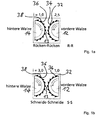
- a back-to-back and a cut-to-cut operating mode (RR and SS operating mode, respectively) are described with reference to FIG Figure 1a and Figure 1b briefly explained below.
- a first roller (front roller) 12 and a second roller (rear roller) 14 are each rotatably mounted about their axis of rotation, the two axes of rotation running parallel to each other and between the two rollers 12, 14 a gap 13 for receiving the ground material.
- the circumferential surface of the front roller 12 is provided with a plurality of elevations (corrugations), each corrugation having a cutting surface (corrugating blade) 32 and a back surface (corrugated back) 34.
- the corrugated ridges are each aligned approximately tangentially to the outer surface of the front roller 12.
- the corrugated cutting edges 32 are approximately perpendicular to the jacket surface of the front roller 12. The same applies accordingly to the corrugating cutting edges 36 and the corrugated back 38 of the rear roller 14.
- the two rollers are driven so that they rotate at opposite speeds. This has the effect that the corrugation of the front roller 12 and the corrugation of the rear roller 14 in the region of the gap 13 move in the transport direction of the ground material (for example from top to bottom).
- the front roller is that roller in which the rear surface of each corrugation, viewed in the direction of movement of the respective corrugation, is in front of the cutting surface of the respective corrugation. That is, in the case of the front roller, the rear surface and then the cutting surface of the corrugation always enter the gap 13 first. In other words, in the front roller, the back surface of a corrugation is forward in the direction of movement and the cutting surface of the corrugation is behind. In the case of the rear roller, on the other hand, the cutting surface of a corrugation is in the front in the direction of movement and the rear surface of the corrugation is behind. In other words: the corrugated cutting edges 32 of the front roller 12 are each facing backwards, while the corrugating cutting edges 36 of the rear roller 14 are each facing forward.
- a change from an RR mode to an SS mode can in principle be achieved in two different ways.
- One possibility is to make the rear roller 14 rotate faster than the front roller 14 in the SS mode.
- Such a change in the speeds is generally not easy to achieve in the roller mills customary today, since the front and rear rollers are controlled by a common motor a common transmission can be driven.
- the transmission usually has little or no setting options.
- the speed ratio between the rear and front rollers is fixed.
- the change from RR to SS mode succeeds in that the two rollers 12, 14 are removed from their respective bearings with the motor at a standstill, then rotated 180 ° about their respective suitable transverse axis and in this rotated position back into their respective storage used to be stored.
- the front roller 12 thus becomes the new rear roller 12 and the rear roller 14 becomes the new front roller 14.
- the US 8,113,447 B1 relates to a process for grinding grain, but it also shows a roller frame, with all four possible operating modes (cutting-cutting, cutting-back, back-cutting, back-back) being possible for the process.
- all four possible operating modes cutting-cutting, cutting-back, back-cutting, back-back
- a method and not Regarding roller mill it cannot be deduced from the naming of the four possible operating modes that one and the same roller mill should control the respective operating modes.
- it is about optimizing the speed difference to maximize the oil yield achieved by the method, whereby it is stated that a maximum oil yield is obtained when the speed difference is in the range of 1.1: 1 and 1.4: 1 and in particular 1 , 3: 1.
- the US 8,480,019 B1 relates to a roller for use in processing grain. It also discloses a corresponding arrangement with two rollers (see there Figure 2 ).
- the cutting-cutting or spine-spine operating modes are not discussed in more detail there. It is only stated that one roller should rotate between 10 and 200% faster than the other roller. For those in there Figure 2 The arrangement shown, this means that it remains within the stated range in any case with back-to-back operation if the left roller is the faster roller. Accordingly, it remains with the cutting-cutting operation if the right roller is the faster.
- the WO 2009/067828 A1 discloses a roller mill which can optionally be equipped with corrugated rollers. It is stated, among other things, that the speed of the first grinding roller and the speed of the second grinding roller can be set independently of one another.
- the above-mentioned roller mill in the commercial school Im Hoppenlau in Stuttgart already provides that the change during operation by changing the speed of the first corrugated roller and / or the speed of the second corrugated roller is changed.
- the drive mechanism of the roller frame is designed so that the speed of the first corrugating roller and / or the speed of the second corrugating roller is possible during operation, that is, while both rollers are rotating normally. There is thus no need to stop the rollers and turn them by 180 ° in order to switch from S-S mode to R-R mode or vice versa.
- the invention is based on the object of lowering the manufacturing and operating costs of the roller mill without restricting functionality.
- the invention provides that the first electrical machine and the second electrical machine have different power ratings. For example, for many applications (for example grinding grain) it can be sufficient if the electrical machine for driving the rear roller has a lower rated power than the electrical machine for driving the front roller. Since motors with a lower nominal power are more cost-effective than comparable motors with a higher nominal power, the manufacturing costs can be reduced. Furthermore, the energy consumption of motors with a lower rated power is lower, so that there is also a reduction in operating costs.
- the ratio of the rated powers of the two electrical machines can be in the range between 1: 1.2 and 1: 5, for example. It is preferably in the range from 1: 2 to 1: 4. This achieves a good compromise between manufacturing costs on the one hand and versatility in use on the other.
- the electrical machine that drives the front corrugated roller has the higher nominal power.
- R-R mode the front roller is the faster of the two corrugated rollers.
- S-S mode the rear roller is the faster, but even in S-S mode, relatively low power is sufficient to drive the rear roller, since relatively low speeds are typically selected in S-S mode.
- a first frequency converter is assigned to the first electrical machine and a second frequency converter is assigned to the second electrical machine.
- the first electrical machine can be connected to an electrical voltage source via the first frequency converter.
- the second electrical machine can be connected to a second voltage source via the second frequency converter.
- the first and second electrical machines are preferably each connected to the same voltage source, for example to a private or public power grid, via the respective frequency converter.
- the voltage source can be an AC voltage source or a DC voltage source.
- the frequency of the voltage supplied by the AC voltage source can be between 20 Hz and 100 Hz, for example.
- Power supply networks generally supply an alternating voltage with an effective voltage of 110 V (for example in the USA) or 220 V (for example in Europe);
- the first and second frequency converters are advantageously suitable for connection to such an alternating voltage network.
- the Control by controlling the first or second frequency converter, the Control the output frequency of the frequency converter concerned and thus the speed of the first or second electrical machine.
- the speed of the first or second electrical machine is identical to the frequency of the output voltage (output frequency) of the first or second frequency converter.
- a first or a second control unit can be provided to control the first or second frequency converter.
- the frequency of the output voltage of the first or second frequency converter can be set by means of the first or second control unit.
- the first and second control units preferably have an operating unit, for example in the form of a rotary knob, for setting the desired output frequency.
- the first and the second control unit can have a common housing.
- one of the two electrical machines is operated as a motor and the other as a generator.
- This case can occur if the faster of the two rollers drives the slower one by frictional engagement and / or frictional engagement via the grist between the two rollers so strongly that the slower roller supplies a net electrical power that can be fed into the power grid or directly back into the electric machine of the faster roller flows.
- the case can also arise that the slower roller is driven partly via the electrical machine assigned to it and partly via frictional engagement and / or frictional engagement with the faster roller.
- the energy generated by the electrical machine operated as a generator is at least partially used to drive the electrical machine operated as a motor.
- This can be implemented, for example, in that the first electrical machine and the second electrical machine are coupled to one another via a power coupler.
- the first corrugated roller and the second corrugated roller have the same roller diameter. This means that the roller mill is equally suitable for both the RR mode and the SS mode.
- the first and the second corrugated roller are preferably identical in construction. This simplifies the manufacture, maintenance and, if necessary, repair of the roller frame.
- the ratio of the speed of the first roller and the speed of the second roller can be varied in the range of 7: 1 and 1: 4.5. This area is considered to be sufficiently large to meet the current requirements with regard to different grist and different required properties of the meal or flour produced.
- a stepless change in a differential speed and a corrugating action number can be brought about.
- a continuously adjustable first or second operating unit is provided for setting the speed of the first corrugating roller and / or for setting the speed of the second corrugating roller.
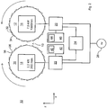
- FIG 2 shows schematically an example of a roller frame 10 with a first corrugated roller (first roller) 12 and a second corrugated roller (second roller) 14.
- the first roller 12 has a multiplicity of first corrugated blades 32 and first corrugated ridges 34.
- the second roller 14 has a plurality of second corrugated cutting edges 36 and second corrugated ridges 38.
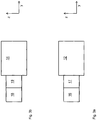
- the roller mill 10 is designed to be operated either in a cutting-edge operating mode or in a back-and-back operating mode. In In the SS mode, the first cutting edges 32 and the second cutting edges 36 are brought closer to one another. In the RR mode of operation, the first ridges 34 and the second ridges 38 are brought closer to one another.
- a change between the SS operating mode and the RR operating mode can take place during ongoing operation by changing the speed of the first roller 12 and / or by changing the speed of the second roller 14.
- the first roller 12 operated as the front roller and the second roller 14 as the rear roller.
- the roller mill 10 comprises a first electrical machine 16 and a second electrical machine 18.
- the first roller 12 is mechanically and / or electromagnetically coupled or can be coupled to the first electrical machine 16, so that the first electrical machine generates a torque (in the example parallel to Y-axis, which is perpendicular to the plane of the drawing) can exert on the first roller 12 in order to cause a rotation of the first roller 12 about its axis of rotation (in the example parallel to the Y-axis).
- the second electrical machine 18 is mechanically or electromagnetically coupled or can be coupled to the second roller 14 and is thus able to exert a torque (in the example parallel to the Y-axis) on the second roller 14 in order to rotate the second roller 14 about it To cause rotation axis (in the example parallel to the Y-axis).
- the first roller 12 and the second roller 14 are operated in opposite directions. That is, the rotation speed vector of the second roller 14 is opposite to the rotation speed vector of the first roller 12.
- the rotational speed vector of the first roller 12 points against the Y direction (out of the plane of the drawing), while the rotational speed vector of the second roller 14 points in the positive Y direction (into the plane of the drawing).
- the two electrical machines 16, 18 can each be an alternating current, a three-phase or a direct current motor, for example.
- the maximum power (or the nominal power) of the first electric machine 16 is higher than the maximum power or the nominal power of the second electric machine 18.
- the maximum speed or the nominal speed of the first electric machine 16 is higher than the maximum speed or the nominal speed of the second electrical machine 18.
- the maximum power and / or the maximum speed of the first machine 16 is usually required in the RR mode.
- the maximum power and / or the maximum speed of the second electrical machine 18 is usually required in SS mode and is less than the maximum power or speed required by the first machine 16.
- the first electrical machine 16 has a nominal power of 7.5 kW and a maximum speed of 1000 revolutions per minute
- the second electrical machine 18 has a nominal power of 2.2 kW and a maximum speed of 200 revolutions per minute.
- the first electrical machine 16 is connected or can be connected to a voltage source 26, for example an alternating current source, via a first frequency converter 20.
- the second electrical machine 18 is connected or can be connected to the voltage source 26 via a second frequency converter 22.
- the voltage source 26 can, for example, be a connection point to an extensive power supply network.
- the voltage source 26 can provide an alternating voltage of 220 V and 50 Hz, for example.
- Each of the two frequency converters 20, 22 uses the input voltage applied to its voltage input (for example the supply voltage supplied by the voltage source 26) to provide an output voltage with a suitable voltage output (which is connected to the first or second electrical machine 16, 18) To generate effective value and suitable frequency.
- the first frequency converter 20 thus supplies the first electrical machine 16 with an alternating voltage with a first frequency F1.
- the second frequency converter 22 supplies the second electrical machine 18 with an alternating voltage with a second frequency F2.
- the roller mill 10 further comprises a first control unit 40 for setting the output frequency F1 generated by the first frequency converter 20 and a second control unit 42 for setting the output frequency F2 generated by the second frequency converter 22.
- the first control unit 40 and the second control unit 42 can each be coupled mechanically, electrically, electromagnetically or electromechanically to the corresponding first or second frequency converter 20, 22.
- the two control units 40, 42 can each have a user and / or a computer interface 44 or 46 in order to enable a user or computer to set the output frequencies F1 and F2 of the frequency converters 20, 22.
- the first frequency converter 20 and the first electrical machine 16 connected to it have a transmission ratio of 1: 1.
- the output voltage of the first frequency converter 20 with frequency F1 generates a corresponding rotation of the first roller 12 with the same frequency, that is to say rotational speed, F1.
- the control units 40, 42 set the speeds D1 and D2 of the first and second rollers 12, 14 individually, in particular during operation, that is, while the rollers 12, 14 are rotating and while they are being supplied with energy by the frequency converters 20, 22. In particular, it is possible in this way to change from an SS mode (in which D2> D1) to an RR mode (in which D1> D2) and vice versa during operation.
- the faster rotating roller transfers energy to the ground material (e.g. grain) through mechanical contact with the slower rotating roller slower roller and thus partially or even completely drives it.
- the electric machine of the slower roller acts as an electric generator.
- the electrical machine acting as a generator (either the first electrical machine 16 or the second electrical machine 18) then supplies electrical energy to the frequency converter (20 or 22) connected to it. In a simple embodiment (not shown), this energy flows at least largely back into the voltage source 26, for example into a power supply network.
- a power coupler 24 is provided, which electrically couples the two frequency converters 20, 22 to one another and thus returns the generated electrical energy to the frequency converter (20 or 22) of the faster rotating roller (12 or 14).
- the voltage source 26 is thus relieved.
- a suitable power coupler is offered by the company Eaton (formerly Moeller), for example. When using the power coupler 24, the speeds of the two rollers 12, 14 can be changed almost arbitrarily and independently of one another, without any major loss of energy.
- the rollers 12, 14 are driven by the respective electrical machine 16 or 18 via a first gear 17 or a second gear 19.
- the two transmissions 17 and 19 can each be a transmission with a fixed (that is, non-adjustable) transmission ratio, since the speeds of the first and second electrical machines 16, 18 can be varied. Manual transmissions can be dispensed with without any significant disadvantages.
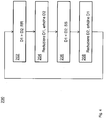
- FIG. 10 illustrates a method 200 of operating a rolling mill, for example, rolling mill 10 of FIG Figure 2 .
- the roller mill is operated in an RR mode. That is, the front roller rotates faster than the rear roller (D1 ⁇ D2).
- the speed D1 of the front roller is reduced and the speed D2 of the rear roller is increased. This can be done during operation by reducing the speed of the first electrical machine and increasing the speed of the second electrical machine.
- the rear roller rotates faster than the front roller. That is, D1 ⁇ D2.
- the rolling mill is now operated in an SS mode.
- phase 208 the speed D1 of the first roller is increased again and the speed D2 of the second roller is reduced again. During operation, this is achieved similarly to phase 204 by increasing the speed of the first electrical machine and reducing the speed of the second electrical machine.
- the rolling mill is now in an RR mode again.
Landscapes
- Engineering & Computer Science (AREA)
- Food Science & Technology (AREA)
- Control Of Multiple Motors (AREA)
- Crushing And Grinding (AREA)
- Perforating, Stamping-Out Or Severing By Means Other Than Cutting (AREA)
Priority Applications (1)
| Application Number | Priority Date | Filing Date | Title |
|---|---|---|---|
| PL16182798T PL3127614T5 (pl) | 2015-08-05 | 2016-08-04 | Młyn walcowy z trybem pracy ostrza-ostrza i trybem pracy grzbiety-grzbiety |
Applications Claiming Priority (1)
| Application Number | Priority Date | Filing Date | Title |
|---|---|---|---|
| DE102015010157.9A DE102015010157A1 (de) | 2015-08-05 | 2015-08-05 | Walzenstuhl mit Schneiden-Schneiden-Betriebsart und Rücken-Rücken-Betriebsart |
Publications (4)
| Publication Number | Publication Date |
|---|---|
| EP3127614A2 EP3127614A2 (de) | 2017-02-08 |
| EP3127614A3 EP3127614A3 (de) | 2017-04-12 |
| EP3127614B1 EP3127614B1 (de) | 2018-04-18 |
| EP3127614B2 true EP3127614B2 (de) | 2020-11-18 |
Family
ID=56571249
Family Applications (1)
| Application Number | Title | Priority Date | Filing Date |
|---|---|---|---|
| EP16182798.5A Active EP3127614B2 (de) | 2015-08-05 | 2016-08-04 | Walzenstuhl mit schneiden-schneiden-betriebsart und rücken-rücken-betriebsart |
Country Status (4)
| Country | Link |
|---|---|
| EP (1) | EP3127614B2 (pl) |
| DE (1) | DE102015010157A1 (pl) |
| HU (1) | HUE038226T2 (pl) |
| PL (1) | PL3127614T5 (pl) |
Families Citing this family (3)
| Publication number | Priority date | Publication date | Assignee | Title |
|---|---|---|---|---|
| CN108787005A (zh) * | 2018-07-03 | 2018-11-13 | 山东永平再生资源股份有限公司 | 废旧物料粉碎机 |
| CN109062134A (zh) * | 2018-09-20 | 2018-12-21 | 安徽马钢设备检修有限公司 | 一种新型四辊破碎电控系统及控制方法 |
| CN118320907B (zh) * | 2024-04-29 | 2024-09-27 | 上海重衡冶金工程技术有限公司 | 一种金属材料快速粉碎装置 |
Citations (5)
| Publication number | Priority date | Publication date | Assignee | Title |
|---|---|---|---|---|
| GB261753A (en) † | 1926-11-17 | 1927-12-01 | Richard Schermann | Improvements relating to the fine grinding of corn |
| DE859558C (de) † | 1949-06-04 | 1952-12-15 | Miag Vertriebs Gmbh | Verbindungstrieb fuer die Walzenpaare von Walzenstuehlen |
| WO2009068921A1 (en) † | 2007-11-26 | 2009-06-04 | Kertesz Andras | High speed roller mill |
| WO2009067828A1 (de) † | 2007-11-27 | 2009-06-04 | Bühler AG | Walzenstuhl |
| US8480019B1 (en) † | 2011-04-01 | 2013-07-09 | Shredlage, L.L.C. | Rolls for use with crop processor, system and method for processing crops |
Family Cites Families (6)
| Publication number | Priority date | Publication date | Assignee | Title |
|---|---|---|---|---|
| DE174199C (pl) | ||||
| DE678825C (de) | 1938-05-29 | 1939-07-26 | Otto Moog Dr Ing | Verfahren und Vorrichtung zum Einstellen von Walzenstuehlen mit stufenlos regelbaren UEbersetzungen |
| DE824290C (de) | 1949-11-26 | 1951-12-10 | Zuendapp Werke G M B H | Mahlanlage zum Schroten und Vermahlen von Getreide und Getreideprodukten |
| DE1033995B (de) | 1953-12-05 | 1958-07-10 | Ludwig Schoeffel | Mehrwalzenmisch- und -reibmaschine |
| DE102007061668A1 (de) | 2007-12-18 | 2009-06-25 | Bühler AG | Walzenstuhl |
| US8113447B1 (en) | 2009-11-05 | 2012-02-14 | Cereal Enterprises, Inc. | Corn milling process |
-
2015
- 2015-08-05 DE DE102015010157.9A patent/DE102015010157A1/de not_active Withdrawn
-
2016
- 2016-08-04 PL PL16182798T patent/PL3127614T5/pl unknown
- 2016-08-04 EP EP16182798.5A patent/EP3127614B2/de active Active
- 2016-08-04 HU HUE16182798A patent/HUE038226T2/hu unknown
Patent Citations (5)
| Publication number | Priority date | Publication date | Assignee | Title |
|---|---|---|---|---|
| GB261753A (en) † | 1926-11-17 | 1927-12-01 | Richard Schermann | Improvements relating to the fine grinding of corn |
| DE859558C (de) † | 1949-06-04 | 1952-12-15 | Miag Vertriebs Gmbh | Verbindungstrieb fuer die Walzenpaare von Walzenstuehlen |
| WO2009068921A1 (en) † | 2007-11-26 | 2009-06-04 | Kertesz Andras | High speed roller mill |
| WO2009067828A1 (de) † | 2007-11-27 | 2009-06-04 | Bühler AG | Walzenstuhl |
| US8480019B1 (en) † | 2011-04-01 | 2013-07-09 | Shredlage, L.L.C. | Rolls for use with crop processor, system and method for processing crops |
Non-Patent Citations (1)
| Title |
|---|
| behauptete offenkundige Vorbenutzung 'Hoppenlau' † |
Also Published As
| Publication number | Publication date |
|---|---|
| HUE038226T2 (hu) | 2018-10-29 |
| PL3127614T3 (pl) | 2018-09-28 |
| EP3127614B1 (de) | 2018-04-18 |
| EP3127614A3 (de) | 2017-04-12 |
| PL3127614T5 (pl) | 2021-08-30 |
| EP3127614A2 (de) | 2017-02-08 |
| DE102015010157A1 (de) | 2017-02-09 |
Similar Documents
| Publication | Publication Date | Title |
|---|---|---|
| EP3127614B2 (de) | Walzenstuhl mit schneiden-schneiden-betriebsart und rücken-rücken-betriebsart | |
| DE102013102603B4 (de) | Verfahren für einen Schwarzstart eines Kraftwerks mit mehreren einem Wechselstromnetz zuschaltbaren Wechselrichtern | |
| DE102012107043B4 (de) | Rollenmühle und Verfahren zum Zerkleinern von Mahlgut mit einer Rollenmühle | |
| DE102008036784B4 (de) | Rollenmühle und Verfahren zur Zerkleinerung von Mahlgut | |
| DE102007021089B3 (de) | Verfahren zur Steuerung parallel geschalteter Ersatzstromquellen und Vorrichtung mit parallel geschalteten Ersatzstromquellen | |
| EP1212549B1 (de) | Antriebsvorrichtung | |
| DE102010014644B4 (de) | Selbstfahrende Arbeitsmaschine mit elektrischem Antriebssystem sowie Verfahren zum Betreiben einer solchen | |
| EP1022123B1 (de) | Verfahren und Vorrichtung zur Herstellung von Polstermaterial sowie Polstermaterial | |
| EP3756260B1 (de) | Mehrkanal-prl: verfahren und system zum erbringen einer regelleistung zum regeln einer netzfrequenz eines stromnetzes sowie stromnetz | |
| DE102014210868A1 (de) | Vorrichtung zur Leistungsübertragung und Maschinenanordnung damit | |
| EP3140041A1 (de) | Walzenmühle und verfahren zur steuerung einer walzenmühle | |
| DE102005037668B4 (de) | Zerkleinerungsvorrichtung mit Drehstrom-Synchronmotor und integrierter Umlaufgetriebestufe | |
| EP3238337B1 (de) | Verfahren zum betreiben eines antriebsstranges | |
| EP2698207B1 (de) | Mehrbereichs-Zweiwellen-Schneidsystem | |
| WO2019091679A1 (de) | Antriebsachse für eine elektrisch angetriebene arbeitsmaschine | |
| DE1293110B (de) | Gruppenantrieb fuer ein kontinuierliches Streckreduzierwalzwerk | |
| AT15388U1 (de) | Triebstrang und Verfahren zum Betreiben eines Triebstranges | |
| WO2022152446A1 (de) | Getriebe und antriebsvorrichtung für ein zumindest teilweise elektrisch angetriebenes fahrzeug | |
| EP4410432A1 (de) | Leistungsverzweigung für eine zerkleinerungsvorrichtung | |
| DE102005019609A1 (de) | Verfahren und Einrichtung zur Nutzung von Windenergie | |
| DE102005022378A1 (de) | Walzenreibmaschine | |
| DE102008040089A1 (de) | Müllereimaschine | |
| EP1358941A1 (de) | Schneidwerkzeug für einen Dokumentenvernichter | |
| DE102011015749A1 (de) | Rotor für eine Zerkleinerungsmaschine und Zerkleinerungseinheit mit einem solchen | |
| CH229941A (de) | Wechselstromerzeugungsanlage für konstante Ausgangsfrequenz bei wechselnder Antriebsdrehzahl. |
Legal Events
| Date | Code | Title | Description |
|---|---|---|---|
| PUAI | Public reference made under article 153(3) epc to a published international application that has entered the european phase |
Free format text: ORIGINAL CODE: 0009012 |
|
| STAA | Information on the status of an ep patent application or granted ep patent |
Free format text: STATUS: THE APPLICATION HAS BEEN PUBLISHED |
|
| AK | Designated contracting states |
Kind code of ref document: A2 Designated state(s): AL AT BE BG CH CY CZ DE DK EE ES FI FR GB GR HR HU IE IS IT LI LT LU LV MC MK MT NL NO PL PT RO RS SE SI SK SM TR |
|
| AX | Request for extension of the european patent |
Extension state: BA ME |
|
| PUAL | Search report despatched |
Free format text: ORIGINAL CODE: 0009013 |
|
| AK | Designated contracting states |
Kind code of ref document: A3 Designated state(s): AL AT BE BG CH CY CZ DE DK EE ES FI FR GB GR HR HU IE IS IT LI LT LU LV MC MK MT NL NO PL PT RO RS SE SI SK SM TR |
|
| AX | Request for extension of the european patent |
Extension state: BA ME |
|
| RIC1 | Information provided on ipc code assigned before grant |
Ipc: B02C 4/08 20060101AFI20170309BHEP Ipc: B02C 4/42 20060101ALI20170309BHEP Ipc: B02C 9/02 20060101ALI20170309BHEP |
|
| STAA | Information on the status of an ep patent application or granted ep patent |
Free format text: STATUS: REQUEST FOR EXAMINATION WAS MADE |
|
| 17P | Request for examination filed |
Effective date: 20171011 |
|
| RBV | Designated contracting states (corrected) |
Designated state(s): AL AT BE BG CH CY CZ DE DK EE ES FI FR GB GR HR HU IE IS IT LI LT LU LV MC MK MT NL NO PL PT RO RS SE SI SK SM TR |
|
| GRAP | Despatch of communication of intention to grant a patent |
Free format text: ORIGINAL CODE: EPIDOSNIGR1 |
|
| STAA | Information on the status of an ep patent application or granted ep patent |
Free format text: STATUS: GRANT OF PATENT IS INTENDED |
|
| RIC1 | Information provided on ipc code assigned before grant |
Ipc: B02C 9/02 20060101ALI20171114BHEP Ipc: B02C 4/42 20060101ALI20171114BHEP Ipc: B02C 4/08 20060101AFI20171114BHEP |
|
| INTG | Intention to grant announced |
Effective date: 20171220 |
|
| GRAS | Grant fee paid |
Free format text: ORIGINAL CODE: EPIDOSNIGR3 |
|
| GRAA | (expected) grant |
Free format text: ORIGINAL CODE: 0009210 |
|
| STAA | Information on the status of an ep patent application or granted ep patent |
Free format text: STATUS: THE PATENT HAS BEEN GRANTED |
|
| AK | Designated contracting states |
Kind code of ref document: B1 Designated state(s): AL AT BE BG CH CY CZ DE DK EE ES FI FR GB GR HR HU IE IS IT LI LT LU LV MC MK MT NL NO PL PT RO RS SE SI SK SM TR |
|
| REG | Reference to a national code |
Ref country code: GB Ref legal event code: FG4D Free format text: NOT ENGLISH |
|
| REG | Reference to a national code |
Ref country code: CH Ref legal event code: EP |
|
| REG | Reference to a national code |
Ref country code: AT Ref legal event code: REF Ref document number: 989860 Country of ref document: AT Kind code of ref document: T Effective date: 20180515 |
|
| REG | Reference to a national code |
Ref country code: IE Ref legal event code: FG4D Free format text: LANGUAGE OF EP DOCUMENT: GERMAN |
|
| REG | Reference to a national code |
Ref country code: DE Ref legal event code: R096 Ref document number: 502016000910 Country of ref document: DE |
|
| REG | Reference to a national code |
Ref country code: NL Ref legal event code: MP Effective date: 20180418 |
|
| REG | Reference to a national code |
Ref country code: FR Ref legal event code: PLFP Year of fee payment: 3 |
|
| REG | Reference to a national code |
Ref country code: CH Ref legal event code: NV Representative=s name: RIEDERER HASLER AND PARTNER PATENTANWAELTE AG, CH |
|
| REG | Reference to a national code |
Ref country code: LT Ref legal event code: MG4D |
|
| PG25 | Lapsed in a contracting state [announced via postgrant information from national office to epo] |
Ref country code: NL Free format text: LAPSE BECAUSE OF FAILURE TO SUBMIT A TRANSLATION OF THE DESCRIPTION OR TO PAY THE FEE WITHIN THE PRESCRIBED TIME-LIMIT Effective date: 20180418 |
|
| REG | Reference to a national code |
Ref country code: HU Ref legal event code: AG4A Ref document number: E038226 Country of ref document: HU |
|
| PG25 | Lapsed in a contracting state [announced via postgrant information from national office to epo] |
Ref country code: ES Free format text: LAPSE BECAUSE OF FAILURE TO SUBMIT A TRANSLATION OF THE DESCRIPTION OR TO PAY THE FEE WITHIN THE PRESCRIBED TIME-LIMIT Effective date: 20180418 Ref country code: LT Free format text: LAPSE BECAUSE OF FAILURE TO SUBMIT A TRANSLATION OF THE DESCRIPTION OR TO PAY THE FEE WITHIN THE PRESCRIBED TIME-LIMIT Effective date: 20180418 Ref country code: NO Free format text: LAPSE BECAUSE OF FAILURE TO SUBMIT A TRANSLATION OF THE DESCRIPTION OR TO PAY THE FEE WITHIN THE PRESCRIBED TIME-LIMIT Effective date: 20180718 Ref country code: FI Free format text: LAPSE BECAUSE OF FAILURE TO SUBMIT A TRANSLATION OF THE DESCRIPTION OR TO PAY THE FEE WITHIN THE PRESCRIBED TIME-LIMIT Effective date: 20180418 Ref country code: BG Free format text: LAPSE BECAUSE OF FAILURE TO SUBMIT A TRANSLATION OF THE DESCRIPTION OR TO PAY THE FEE WITHIN THE PRESCRIBED TIME-LIMIT Effective date: 20180718 Ref country code: AL Free format text: LAPSE BECAUSE OF FAILURE TO SUBMIT A TRANSLATION OF THE DESCRIPTION OR TO PAY THE FEE WITHIN THE PRESCRIBED TIME-LIMIT Effective date: 20180418 Ref country code: SE Free format text: LAPSE BECAUSE OF FAILURE TO SUBMIT A TRANSLATION OF THE DESCRIPTION OR TO PAY THE FEE WITHIN THE PRESCRIBED TIME-LIMIT Effective date: 20180418 |
|
| PG25 | Lapsed in a contracting state [announced via postgrant information from national office to epo] |
Ref country code: GR Free format text: LAPSE BECAUSE OF FAILURE TO SUBMIT A TRANSLATION OF THE DESCRIPTION OR TO PAY THE FEE WITHIN THE PRESCRIBED TIME-LIMIT Effective date: 20180719 Ref country code: HR Free format text: LAPSE BECAUSE OF FAILURE TO SUBMIT A TRANSLATION OF THE DESCRIPTION OR TO PAY THE FEE WITHIN THE PRESCRIBED TIME-LIMIT Effective date: 20180418 Ref country code: RS Free format text: LAPSE BECAUSE OF FAILURE TO SUBMIT A TRANSLATION OF THE DESCRIPTION OR TO PAY THE FEE WITHIN THE PRESCRIBED TIME-LIMIT Effective date: 20180418 Ref country code: LV Free format text: LAPSE BECAUSE OF FAILURE TO SUBMIT A TRANSLATION OF THE DESCRIPTION OR TO PAY THE FEE WITHIN THE PRESCRIBED TIME-LIMIT Effective date: 20180418 |
|
| PG25 | Lapsed in a contracting state [announced via postgrant information from national office to epo] |
Ref country code: PT Free format text: LAPSE BECAUSE OF FAILURE TO SUBMIT A TRANSLATION OF THE DESCRIPTION OR TO PAY THE FEE WITHIN THE PRESCRIBED TIME-LIMIT Effective date: 20180820 |
|
| REG | Reference to a national code |
Ref country code: DE Ref legal event code: R026 Ref document number: 502016000910 Country of ref document: DE |
|
| PLBI | Opposition filed |
Free format text: ORIGINAL CODE: 0009260 |
|
| PLAX | Notice of opposition and request to file observation + time limit sent |
Free format text: ORIGINAL CODE: EPIDOSNOBS2 |
|
| PG25 | Lapsed in a contracting state [announced via postgrant information from national office to epo] |
Ref country code: RO Free format text: LAPSE BECAUSE OF FAILURE TO SUBMIT A TRANSLATION OF THE DESCRIPTION OR TO PAY THE FEE WITHIN THE PRESCRIBED TIME-LIMIT Effective date: 20180418 Ref country code: SK Free format text: LAPSE BECAUSE OF FAILURE TO SUBMIT A TRANSLATION OF THE DESCRIPTION OR TO PAY THE FEE WITHIN THE PRESCRIBED TIME-LIMIT Effective date: 20180418 Ref country code: DK Free format text: LAPSE BECAUSE OF FAILURE TO SUBMIT A TRANSLATION OF THE DESCRIPTION OR TO PAY THE FEE WITHIN THE PRESCRIBED TIME-LIMIT Effective date: 20180418 Ref country code: EE Free format text: LAPSE BECAUSE OF FAILURE TO SUBMIT A TRANSLATION OF THE DESCRIPTION OR TO PAY THE FEE WITHIN THE PRESCRIBED TIME-LIMIT Effective date: 20180418 |
|
| 26 | Opposition filed |
Opponent name: BAUERMEISTER ZERKLEINERUNGSTECHNIK GMBH Effective date: 20190118 Opponent name: RUECKERT MUEHLEN- UND ANLAGENTECHNIK GMBH & CO. KG Effective date: 20190117 Opponent name: BUEHLER AG Effective date: 20190118 |
|
| PG25 | Lapsed in a contracting state [announced via postgrant information from national office to epo] |
Ref country code: SM Free format text: LAPSE BECAUSE OF FAILURE TO SUBMIT A TRANSLATION OF THE DESCRIPTION OR TO PAY THE FEE WITHIN THE PRESCRIBED TIME-LIMIT Effective date: 20180418 |
|
| PG25 | Lapsed in a contracting state [announced via postgrant information from national office to epo] |
Ref country code: MC Free format text: LAPSE BECAUSE OF FAILURE TO SUBMIT A TRANSLATION OF THE DESCRIPTION OR TO PAY THE FEE WITHIN THE PRESCRIBED TIME-LIMIT Effective date: 20180418 |
|
| PG25 | Lapsed in a contracting state [announced via postgrant information from national office to epo] |
Ref country code: LU Free format text: LAPSE BECAUSE OF NON-PAYMENT OF DUE FEES Effective date: 20180804 |
|
| REG | Reference to a national code |
Ref country code: IE Ref legal event code: MM4A |
|
| PG25 | Lapsed in a contracting state [announced via postgrant information from national office to epo] |
Ref country code: SI Free format text: LAPSE BECAUSE OF FAILURE TO SUBMIT A TRANSLATION OF THE DESCRIPTION OR TO PAY THE FEE WITHIN THE PRESCRIBED TIME-LIMIT Effective date: 20180418 |
|
| PLBB | Reply of patent proprietor to notice(s) of opposition received |
Free format text: ORIGINAL CODE: EPIDOSNOBS3 |
|
| PG25 | Lapsed in a contracting state [announced via postgrant information from national office to epo] |
Ref country code: IE Free format text: LAPSE BECAUSE OF NON-PAYMENT OF DUE FEES Effective date: 20180804 |
|
| PLAY | Examination report in opposition despatched + time limit |
Free format text: ORIGINAL CODE: EPIDOSNORE2 |
|
| PLBP | Opposition withdrawn |
Free format text: ORIGINAL CODE: 0009264 |
|
| PGFP | Annual fee paid to national office [announced via postgrant information from national office to epo] |
Ref country code: FR Payment date: 20190822 Year of fee payment: 4 Ref country code: CZ Payment date: 20190725 Year of fee payment: 4 |
|
| PLBP | Opposition withdrawn |
Free format text: ORIGINAL CODE: 0009264 |
|
| PGFP | Annual fee paid to national office [announced via postgrant information from national office to epo] |
Ref country code: HU Payment date: 20190726 Year of fee payment: 4 Ref country code: BE Payment date: 20190821 Year of fee payment: 4 |
|
| PLBP | Opposition withdrawn |
Free format text: ORIGINAL CODE: 0009264 |
|
| PLBC | Reply to examination report in opposition received |
Free format text: ORIGINAL CODE: EPIDOSNORE3 |
|
| PG25 | Lapsed in a contracting state [announced via postgrant information from national office to epo] |
Ref country code: MT Free format text: LAPSE BECAUSE OF FAILURE TO SUBMIT A TRANSLATION OF THE DESCRIPTION OR TO PAY THE FEE WITHIN THE PRESCRIBED TIME-LIMIT Effective date: 20180418 |
|
| PG25 | Lapsed in a contracting state [announced via postgrant information from national office to epo] |
Ref country code: CY Free format text: LAPSE BECAUSE OF FAILURE TO SUBMIT A TRANSLATION OF THE DESCRIPTION OR TO PAY THE FEE WITHIN THE PRESCRIBED TIME-LIMIT Effective date: 20180418 Ref country code: MK Free format text: LAPSE BECAUSE OF NON-PAYMENT OF DUE FEES Effective date: 20180418 |
|
| PG25 | Lapsed in a contracting state [announced via postgrant information from national office to epo] |
Ref country code: IS Free format text: LAPSE BECAUSE OF FAILURE TO SUBMIT A TRANSLATION OF THE DESCRIPTION OR TO PAY THE FEE WITHIN THE PRESCRIBED TIME-LIMIT Effective date: 20180818 |
|
| PUAH | Patent maintained in amended form |
Free format text: ORIGINAL CODE: 0009272 |
|
| STAA | Information on the status of an ep patent application or granted ep patent |
Free format text: STATUS: PATENT MAINTAINED AS AMENDED |
|
| REG | Reference to a national code |
Ref country code: CH Ref legal event code: AELC |
|
| 27A | Patent maintained in amended form |
Effective date: 20201118 |
|
| AK | Designated contracting states |
Kind code of ref document: B2 Designated state(s): AL AT BE BG CH CY CZ DE DK EE ES FI FR GB GR HR HU IE IS IT LI LT LU LV MC MK MT NL NO PL PT RO RS SE SI SK SM TR |
|
| REG | Reference to a national code |
Ref country code: DE Ref legal event code: R102 Ref document number: 502016000910 Country of ref document: DE |
|
| GBPC | Gb: european patent ceased through non-payment of renewal fee |
Effective date: 20200804 |
|
| PG25 | Lapsed in a contracting state [announced via postgrant information from national office to epo] |
Ref country code: HU Free format text: LAPSE BECAUSE OF NON-PAYMENT OF DUE FEES Effective date: 20200805 Ref country code: CZ Free format text: LAPSE BECAUSE OF NON-PAYMENT OF DUE FEES Effective date: 20200804 |
|
| REG | Reference to a national code |
Ref country code: BE Ref legal event code: MM Effective date: 20200831 |
|
| PG25 | Lapsed in a contracting state [announced via postgrant information from national office to epo] |
Ref country code: FR Free format text: LAPSE BECAUSE OF NON-PAYMENT OF DUE FEES Effective date: 20200831 |
|
| PG25 | Lapsed in a contracting state [announced via postgrant information from national office to epo] |
Ref country code: BE Free format text: LAPSE BECAUSE OF NON-PAYMENT OF DUE FEES Effective date: 20200831 Ref country code: GB Free format text: LAPSE BECAUSE OF NON-PAYMENT OF DUE FEES Effective date: 20200804 |
|
| PGFP | Annual fee paid to national office [announced via postgrant information from national office to epo] |
Ref country code: TR Payment date: 20220826 Year of fee payment: 7 Ref country code: AT Payment date: 20220818 Year of fee payment: 7 |
|
| PGFP | Annual fee paid to national office [announced via postgrant information from national office to epo] |
Ref country code: PL Payment date: 20220802 Year of fee payment: 7 |
|
| P01 | Opt-out of the competence of the unified patent court (upc) registered |
Effective date: 20230622 |
|
| REG | Reference to a national code |
Ref country code: AT Ref legal event code: MM01 Ref document number: 989860 Country of ref document: AT Kind code of ref document: T Effective date: 20230804 |
|
| PG25 | Lapsed in a contracting state [announced via postgrant information from national office to epo] |
Ref country code: AT Free format text: LAPSE BECAUSE OF NON-PAYMENT OF DUE FEES Effective date: 20230804 |
|
| PG25 | Lapsed in a contracting state [announced via postgrant information from national office to epo] |
Ref country code: AT Free format text: LAPSE BECAUSE OF NON-PAYMENT OF DUE FEES Effective date: 20230804 |
|
| PG25 | Lapsed in a contracting state [announced via postgrant information from national office to epo] |
Ref country code: PL Free format text: LAPSE BECAUSE OF NON-PAYMENT OF DUE FEES Effective date: 20230804 |
|
| PGFP | Annual fee paid to national office [announced via postgrant information from national office to epo] |
Ref country code: DE Payment date: 20250820 Year of fee payment: 10 |
|
| PGFP | Annual fee paid to national office [announced via postgrant information from national office to epo] |
Ref country code: IT Payment date: 20250829 Year of fee payment: 10 |
|
| PGFP | Annual fee paid to national office [announced via postgrant information from national office to epo] |
Ref country code: CH Payment date: 20250901 Year of fee payment: 10 |
|
| REG | Reference to a national code |
Ref country code: DE Ref legal event code: R082 Ref document number: 502016000910 Country of ref document: DE Representative=s name: PUSCHMANN BORCHERT KAISER KLETTNER PATENTANWAE, DE Ref country code: DE Ref legal event code: R082 Ref document number: 502016000910 Country of ref document: DE Representative=s name: PATCARE PATENTANWAELTE PARTNERSCHAFT MBB, DE |