EP3127618A1 - Vorformbeschichtungsvorrichtung, verfahren zur herstellung einer vorform und verfahren zur herstellung einer kunststoffflasche - Google Patents
Vorformbeschichtungsvorrichtung, verfahren zur herstellung einer vorform und verfahren zur herstellung einer kunststoffflasche Download PDFInfo
- Publication number
- EP3127618A1 EP3127618A1 EP15773631.5A EP15773631A EP3127618A1 EP 3127618 A1 EP3127618 A1 EP 3127618A1 EP 15773631 A EP15773631 A EP 15773631A EP 3127618 A1 EP3127618 A1 EP 3127618A1
- Authority
- EP
- European Patent Office
- Prior art keywords
- preform
- outer circumferential
- circumferential surface
- transfer roller
- coating solution
- Prior art date
- Legal status (The legal status is an assumption and is not a legal conclusion. Google has not performed a legal analysis and makes no representation as to the accuracy of the status listed.)
- Withdrawn
Links
- 239000011248 coating agent Substances 0.000 title claims abstract description 153
- 238000000576 coating method Methods 0.000 title claims abstract description 148
- 229920003023 plastic Polymers 0.000 title claims description 36
- 239000004033 plastic Substances 0.000 title claims description 36
- 238000000034 method Methods 0.000 title claims description 24
- 238000004519 manufacturing process Methods 0.000 title claims description 14
- 238000011084 recovery Methods 0.000 claims description 9
- 238000000071 blow moulding Methods 0.000 claims description 8
- 238000001035 drying Methods 0.000 claims description 8
- 230000002093 peripheral effect Effects 0.000 abstract 5
- 239000007788 liquid Substances 0.000 abstract 2
- 239000000243 solution Substances 0.000 description 125
- 239000004372 Polyvinyl alcohol Substances 0.000 description 17
- 229920002451 polyvinyl alcohol Polymers 0.000 description 17
- 239000010408 film Substances 0.000 description 11
- 230000004888 barrier function Effects 0.000 description 9
- 238000007598 dipping method Methods 0.000 description 9
- XLYOFNOQVPJJNP-UHFFFAOYSA-N water Substances O XLYOFNOQVPJJNP-UHFFFAOYSA-N 0.000 description 7
- 239000007789 gas Substances 0.000 description 6
- 229920000139 polyethylene terephthalate Polymers 0.000 description 5
- 239000005020 polyethylene terephthalate Substances 0.000 description 5
- 239000011253 protective coating Substances 0.000 description 5
- 229920005989 resin Polymers 0.000 description 5
- 239000011347 resin Substances 0.000 description 5
- CURLTUGMZLYLDI-UHFFFAOYSA-N Carbon dioxide Chemical compound O=C=O CURLTUGMZLYLDI-UHFFFAOYSA-N 0.000 description 4
- 230000007547 defect Effects 0.000 description 4
- -1 polyethylene terephthalate Polymers 0.000 description 4
- 229920000219 Ethylene vinyl alcohol Polymers 0.000 description 2
- 239000004698 Polyethylene Substances 0.000 description 2
- 239000004743 Polypropylene Substances 0.000 description 2
- QVGXLLKOCUKJST-UHFFFAOYSA-N atomic oxygen Chemical compound [O] QVGXLLKOCUKJST-UHFFFAOYSA-N 0.000 description 2
- 235000013361 beverage Nutrition 0.000 description 2
- 239000011230 binding agent Substances 0.000 description 2
- 229910002092 carbon dioxide Inorganic materials 0.000 description 2
- 239000001569 carbon dioxide Substances 0.000 description 2
- 238000007599 discharging Methods 0.000 description 2
- 239000006185 dispersion Substances 0.000 description 2
- 230000000694 effects Effects 0.000 description 2
- 230000005484 gravity Effects 0.000 description 2
- 238000001746 injection moulding Methods 0.000 description 2
- 229910052760 oxygen Inorganic materials 0.000 description 2
- 239000001301 oxygen Substances 0.000 description 2
- 229920002037 poly(vinyl butyral) polymer Polymers 0.000 description 2
- 229920000573 polyethylene Polymers 0.000 description 2
- 229920000098 polyolefin Polymers 0.000 description 2
- 229920001155 polypropylene Polymers 0.000 description 2
- OKTJSMMVPCPJKN-UHFFFAOYSA-N Carbon Chemical compound [C] OKTJSMMVPCPJKN-UHFFFAOYSA-N 0.000 description 1
- 239000004593 Epoxy Substances 0.000 description 1
- JOYRKODLDBILNP-UHFFFAOYSA-N Ethyl urethane Chemical compound CCOC(N)=O JOYRKODLDBILNP-UHFFFAOYSA-N 0.000 description 1
- ISWSIDIOOBJBQZ-UHFFFAOYSA-N Phenol Chemical compound OC1=CC=CC=C1 ISWSIDIOOBJBQZ-UHFFFAOYSA-N 0.000 description 1
- 239000004952 Polyamide Substances 0.000 description 1
- 229920000954 Polyglycolide Polymers 0.000 description 1
- 239000002250 absorbent Substances 0.000 description 1
- 230000002745 absorbent Effects 0.000 description 1
- 230000015572 biosynthetic process Effects 0.000 description 1
- 238000007664 blowing Methods 0.000 description 1
- 229910052799 carbon Inorganic materials 0.000 description 1
- 238000000748 compression moulding Methods 0.000 description 1
- 238000007796 conventional method Methods 0.000 description 1
- 238000001816 cooling Methods 0.000 description 1
- 238000003851 corona treatment Methods 0.000 description 1
- 238000010894 electron beam technology Methods 0.000 description 1
- 239000004715 ethylene vinyl alcohol Substances 0.000 description 1
- 238000010438 heat treatment Methods 0.000 description 1
- 239000012943 hotmelt Substances 0.000 description 1
- 238000007689 inspection Methods 0.000 description 1
- 239000000463 material Substances 0.000 description 1
- 239000011259 mixed solution Substances 0.000 description 1
- 238000009832 plasma treatment Methods 0.000 description 1
- 229920002239 polyacrylonitrile Polymers 0.000 description 1
- 229920002647 polyamide Polymers 0.000 description 1
- 229920000728 polyester Polymers 0.000 description 1
- 239000004633 polyglycolic acid Substances 0.000 description 1
- 239000005033 polyvinylidene chloride Substances 0.000 description 1
- 230000010349 pulsation Effects 0.000 description 1
- 238000007790 scraping Methods 0.000 description 1
- 239000002904 solvent Substances 0.000 description 1
- 238000003860 storage Methods 0.000 description 1
- 238000004381 surface treatment Methods 0.000 description 1
- 229920001169 thermoplastic Polymers 0.000 description 1
- 229920001187 thermosetting polymer Polymers 0.000 description 1
- 239000004416 thermosoftening plastic Substances 0.000 description 1
- 239000010409 thin film Substances 0.000 description 1
Images


Classifications
-
- B—PERFORMING OPERATIONS; TRANSPORTING
- B29—WORKING OF PLASTICS; WORKING OF SUBSTANCES IN A PLASTIC STATE IN GENERAL
- B29C—SHAPING OR JOINING OF PLASTICS; SHAPING OF MATERIAL IN A PLASTIC STATE, NOT OTHERWISE PROVIDED FOR; AFTER-TREATMENT OF THE SHAPED PRODUCTS, e.g. REPAIRING
- B29C49/00—Blow-moulding, i.e. blowing a preform or parison to a desired shape within a mould; Apparatus therefor
- B29C49/02—Combined blow-moulding and manufacture of the preform or the parison
- B29C49/06—Injection blow-moulding
-
- B—PERFORMING OPERATIONS; TRANSPORTING
- B05—SPRAYING OR ATOMISING IN GENERAL; APPLYING FLUENT MATERIALS TO SURFACES, IN GENERAL
- B05C—APPARATUS FOR APPLYING FLUENT MATERIALS TO SURFACES, IN GENERAL
- B05C1/00—Apparatus in which liquid or other fluent material is applied to the surface of the work by contact with a member carrying the liquid or other fluent material, e.g. a porous member loaded with a liquid to be applied as a coating
- B05C1/02—Apparatus in which liquid or other fluent material is applied to the surface of the work by contact with a member carrying the liquid or other fluent material, e.g. a porous member loaded with a liquid to be applied as a coating for applying liquid or other fluent material to separate articles
- B05C1/022—Apparatus in which liquid or other fluent material is applied to the surface of the work by contact with a member carrying the liquid or other fluent material, e.g. a porous member loaded with a liquid to be applied as a coating for applying liquid or other fluent material to separate articles to the outer surface of hollow articles
-
- B—PERFORMING OPERATIONS; TRANSPORTING
- B05—SPRAYING OR ATOMISING IN GENERAL; APPLYING FLUENT MATERIALS TO SURFACES, IN GENERAL
- B05D—PROCESSES FOR APPLYING FLUENT MATERIALS TO SURFACES, IN GENERAL
- B05D1/00—Processes for applying liquids or other fluent materials
- B05D1/28—Processes for applying liquids or other fluent materials performed by transfer from the surfaces of elements carrying the liquid or other fluent material, e.g. brushes, pads, rollers
-
- B—PERFORMING OPERATIONS; TRANSPORTING
- B05—SPRAYING OR ATOMISING IN GENERAL; APPLYING FLUENT MATERIALS TO SURFACES, IN GENERAL
- B05D—PROCESSES FOR APPLYING FLUENT MATERIALS TO SURFACES, IN GENERAL
- B05D3/00—Pretreatment of surfaces to which liquids or other fluent materials are to be applied; After-treatment of applied coatings, e.g. intermediate treating of an applied coating preparatory to subsequent applications of liquids or other fluent materials
- B05D3/007—After-treatment
-
- B—PERFORMING OPERATIONS; TRANSPORTING
- B05—SPRAYING OR ATOMISING IN GENERAL; APPLYING FLUENT MATERIALS TO SURFACES, IN GENERAL
- B05D—PROCESSES FOR APPLYING FLUENT MATERIALS TO SURFACES, IN GENERAL
- B05D7/00—Processes, other than flocking, specially adapted for applying liquids or other fluent materials to particular surfaces or for applying particular liquids or other fluent materials
- B05D7/22—Processes, other than flocking, specially adapted for applying liquids or other fluent materials to particular surfaces or for applying particular liquids or other fluent materials to internal surfaces, e.g. of tubes
- B05D7/227—Processes, other than flocking, specially adapted for applying liquids or other fluent materials to particular surfaces or for applying particular liquids or other fluent materials to internal surfaces, e.g. of tubes of containers, cans or the like
-
- B—PERFORMING OPERATIONS; TRANSPORTING
- B29—WORKING OF PLASTICS; WORKING OF SUBSTANCES IN A PLASTIC STATE IN GENERAL
- B29B—PREPARATION OR PRETREATMENT OF THE MATERIAL TO BE SHAPED; MAKING GRANULES OR PREFORMS; RECOVERY OF PLASTICS OR OTHER CONSTITUENTS OF WASTE MATERIAL CONTAINING PLASTICS
- B29B11/00—Making preforms
-
- B—PERFORMING OPERATIONS; TRANSPORTING
- B65—CONVEYING; PACKING; STORING; HANDLING THIN OR FILAMENTARY MATERIAL
- B65D—CONTAINERS FOR STORAGE OR TRANSPORT OF ARTICLES OR MATERIALS, e.g. BAGS, BARRELS, BOTTLES, BOXES, CANS, CARTONS, CRATES, DRUMS, JARS, TANKS, HOPPERS, FORWARDING CONTAINERS; ACCESSORIES, CLOSURES, OR FITTINGS THEREFOR; PACKAGING ELEMENTS; PACKAGES
- B65D23/00—Details of bottles or jars not otherwise provided for
- B65D23/08—Coverings or external coatings
- B65D23/0807—Coatings
-
- B—PERFORMING OPERATIONS; TRANSPORTING
- B05—SPRAYING OR ATOMISING IN GENERAL; APPLYING FLUENT MATERIALS TO SURFACES, IN GENERAL
- B05C—APPARATUS FOR APPLYING FLUENT MATERIALS TO SURFACES, IN GENERAL
- B05C1/00—Apparatus in which liquid or other fluent material is applied to the surface of the work by contact with a member carrying the liquid or other fluent material, e.g. a porous member loaded with a liquid to be applied as a coating
- B05C1/04—Apparatus in which liquid or other fluent material is applied to the surface of the work by contact with a member carrying the liquid or other fluent material, e.g. a porous member loaded with a liquid to be applied as a coating for applying liquid or other fluent material to work of indefinite length
- B05C1/08—Apparatus in which liquid or other fluent material is applied to the surface of the work by contact with a member carrying the liquid or other fluent material, e.g. a porous member loaded with a liquid to be applied as a coating for applying liquid or other fluent material to work of indefinite length using a roller or other rotating member which contacts the work along a generating line
- B05C1/0813—Apparatus in which liquid or other fluent material is applied to the surface of the work by contact with a member carrying the liquid or other fluent material, e.g. a porous member loaded with a liquid to be applied as a coating for applying liquid or other fluent material to work of indefinite length using a roller or other rotating member which contacts the work along a generating line characterised by means for supplying liquid or other fluent material to the roller
-
- B—PERFORMING OPERATIONS; TRANSPORTING
- B05—SPRAYING OR ATOMISING IN GENERAL; APPLYING FLUENT MATERIALS TO SURFACES, IN GENERAL
- B05D—PROCESSES FOR APPLYING FLUENT MATERIALS TO SURFACES, IN GENERAL
- B05D2201/00—Polymeric substrate or laminate
-
- B—PERFORMING OPERATIONS; TRANSPORTING
- B29—WORKING OF PLASTICS; WORKING OF SUBSTANCES IN A PLASTIC STATE IN GENERAL
- B29C—SHAPING OR JOINING OF PLASTICS; SHAPING OF MATERIAL IN A PLASTIC STATE, NOT OTHERWISE PROVIDED FOR; AFTER-TREATMENT OF THE SHAPED PRODUCTS, e.g. REPAIRING
- B29C49/00—Blow-moulding, i.e. blowing a preform or parison to a desired shape within a mould; Apparatus therefor
- B29C49/02—Combined blow-moulding and manufacture of the preform or the parison
- B29C2049/023—Combined blow-moulding and manufacture of the preform or the parison using inherent heat of the preform, i.e. 1 step blow moulding
-
- B—PERFORMING OPERATIONS; TRANSPORTING
- B29—WORKING OF PLASTICS; WORKING OF SUBSTANCES IN A PLASTIC STATE IN GENERAL
- B29C—SHAPING OR JOINING OF PLASTICS; SHAPING OF MATERIAL IN A PLASTIC STATE, NOT OTHERWISE PROVIDED FOR; AFTER-TREATMENT OF THE SHAPED PRODUCTS, e.g. REPAIRING
- B29C2949/00—Indexing scheme relating to blow-moulding
- B29C2949/30—Preforms or parisons made of several components
- B29C2949/3064—Preforms or parisons made of several components having at least one components being applied using techniques not covered by B29C2949/3032 - B29C2949/3062
- B29C2949/3074—Preforms or parisons made of several components having at least one components being applied using techniques not covered by B29C2949/3032 - B29C2949/3062 said at least one component obtained by coating
-
- B—PERFORMING OPERATIONS; TRANSPORTING
- B29—WORKING OF PLASTICS; WORKING OF SUBSTANCES IN A PLASTIC STATE IN GENERAL
- B29L—INDEXING SCHEME ASSOCIATED WITH SUBCLASS B29C, RELATING TO PARTICULAR ARTICLES
- B29L2009/00—Layered products
- B29L2009/005—Layered products coated
-
- B—PERFORMING OPERATIONS; TRANSPORTING
- B29—WORKING OF PLASTICS; WORKING OF SUBSTANCES IN A PLASTIC STATE IN GENERAL
- B29L—INDEXING SCHEME ASSOCIATED WITH SUBCLASS B29C, RELATING TO PARTICULAR ARTICLES
- B29L2031/00—Other particular articles
- B29L2031/712—Containers; Packaging elements or accessories, Packages
- B29L2031/7158—Bottles
Definitions
- the present invention relates to a preform coating device for coating a preform of a plastic bottle with a coating solution, a method for manufacturing a preform, and a method for manufacturing a plastic bottle.
- PET bottles polyethylene terephthalate
- the plastic bottles are formed by expanding the test tube shaped preforms by stretch blow molding.
- a barrier coating on the outer circumferential surface of the preform.
- the barrier coating is formed by applying a coating solution to the outer circumferential surface of the preform and drying the outer circumferential surface of the preform.
- a coating solution is typically applied, as shown in FIG. 6 , by dipping the preform in the coating solution in the vertical direction.
- the film thickness of the coating solution gradually increases the further downward in the vertical direction.
- the barrier performance reducing the passage of gases becomes uneven on the outer circumferential surface of the preform and in turn the plastic bottle.
- the parts where the film thickness is thin are sometimes excessively heated and whitened.
- the bottom part of the preform is also applied with the coating solution, so the drying time of the coating solution becomes longer. For this reason, if making the coating solution of the bottom part with a thick film thickness dry, the cylindrical body part of the preform with a thin film thickness becomes excessively heated, so tends to whiten.
- the present invention was made in consideration of the above problem and has as its object to make the film thickness of the coating solution applied to the outer circumferential surface of a preform for a plastic bottle thin and uniform so as to reduce the occurrence of defects of a preform or plastic bottle.
- a preform coating device comprising a columnar shaped transfer roller rotating about its center axis and an application device for applying a coating solution with a predetermined thickness to an outer circumferential surface of the transfer roller, wherein the outer circumferential surface of the transfer roller rotates in contact with an outer circumferential surface of a preform whereby the coating solution is transferred from the outer circumferential surface of the transfer roller to the outer circumferential surface of the preform.
- the application device is a die coater formed with a slot and configured so as to discharge coating solution from the slot to the outer circumferential surface of the transfer roller.
- the preform coating device further comprises a conveyor device conveying the preform, and a conveyance path of the preform includes a substantially arc shaped path along the outer circumferential surface of the transfer roller.
- the coating solution is transferred from the outer circumferential surface of the transfer roller to only a cylindrical body part of the preform.
- the preform coating device further comprises a scraper configured so as to scrape off the coating solution not transferred to the outer circumferential surface of the preform from the outer circumferential surface of the transfer roller.
- the preform coating device further comprises a solution recovery tank recovering the coating solution scraped off by the scraper and a defoaming device removing bubbles from the recovered coating solution.
- a method for manufacturing a preform comprising: a step of applying a coating solution with a predetermined thickness to an outer circumferential surface of a columnar shaped transfer roller rotating about its center axis by an application device, a step of conveying a preform on the outer circumferential surface of the transfer roller and transferring the coating solution from the outer circumferential surface of the transfer roller to the outer circumferential surface of the preform, and a step of drying the outer circumferential surface of the preform.
- the coating solution is transferred from the outer circumferential surface of the transfer roller to only a cylindrical body part of the preform.
- the preform is continuously conveyed on the outer circumferential surface of the transfer roller.
- the coating solution not transferred to the outer circumferential surface of the preform is recovered, is deformed and is again applied to the outer circumferential surface of the transfer roller by the application device.
- the coating solution has a viscosity of 100 mPa ⁇ s or more.
- a method for manufacturing a plastic bottle including stretch blow molding a preform manufactured by the second embodiment of the present invention.
- the present invention it is possible to make the film thickness of the coating solution applied to the outer circumferential surface of a preform for a plastic bottle uniformly thin and in turn reduce the occurrence of defects of a preform or plastic bottle.
- a plastic bottle means a bottle made of a plastic like polyethylene terephthalate (PET), polypropylene (PP), and polyethylene (PE) and is not limited to a PET bottle.
- PET polyethylene terephthalate
- PP polypropylene
- PE polyethylene
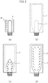
- FIG. 1 shows a preform 1 for a plastic bottle.
- the preform 1 is formed from a resin by the injection molding method or the PCM (preform compression molding) method.
- the preform 1 is comprised of a mouth part 1a fitting with a cap of the plastic bottle, a cylindrical body part 1b adjoining the mouth part 1a, and a bottom part 1c closing one end of the cylindrical body part 1b and has a shape like a test tube.
- a male thread for engaging with the female thread of the cap is formed at the outer circumferential surface of the mouth part 1a.
- the end part of the mouth part 1a side of the preform 1 is open.
- the outer circumferential surface of the preform 1 is formed with a barrier coating.
- the barrier coating is formed by applying a coating solution to the outer circumferential surface of the preform 1 and drying the outer circumferential surface of the preform 1.
- FIGS. 2A to 2D show the stretch blow molding method for forming a plastic bottle 3 from the preform 1.
- the preform 1 is heated by a heater 40.
- the preform 1 is inserted into a mold 2 and the mold 2 is closed.
- the preform 1 is stretched by a stretch rod (not shown) in the vertical direction and is stretched by pressurized air in the horizontal direction.
- FIG. 2D if the preform 1 is expanded to the desired shape, the inside surface of the plastic bottle 3 is cooled by cooling air. Finally, the plastic bottle 3 is taken out from the mold 2.
- FIG. 3 shows a plastic bottle 3 formed from the preform 1.
- FIG. 4 and FIG. 5 a preform coating device according to an embodiment of the present invention will be explained.
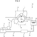
- FIG. 4 is a schematic view of a preform coating device 10 according to an embodiment of the present invention.
- the preform coating device 10 applies a coating solution to the outer circumferential surface of the preform 1.
- the preform coating device 10 comprises a transfer roller 11, a conveyor device 12 conveying a preform 1 on the outer circumferential surface of the transfer roller 11, a die coater 13 discharging a coating solution to the outer circumferential surface of the transfer roller 11, a solution holding tank 14 holding the coating solution to be supplied to the die coater 13, and a pump 15 supplying the coating solution from the solution holding tank 14 to the die coater 13.
- the transfer roller 11 has a columnar shape and rotates about its center axis 111.
- the transfer roller 11 is rotated by turning a handle connected to the center axis 111 by hand or by using a motor etc. to make the transfer roller 11 rotate about the center axis 111.
- the conveyance path of the preform 1 is shown by the arrows in FIG. 4 .
- the conveyance path of the preform 1 by the conveyor device 12 includes a substantially arc shaped path along the outer circumferential surface of the transfer roller 11. If the preform 1 is conveyed by the conveyor device 12 on the outer circumferential surface of the transfer roller 11, the outer circumferential surface of the preform 1 continuously rotates in contact with the outer circumferential surface of the transfer roller 11, to which the coating solution is applied, along the substantially arc shaped path along the outer circumferential surface of the transfer roller 11. Due to this, the preform 1 can be made to move while transferring the coating solution from the outer circumferential surface of the transfer roller 11 to the outer circumferential surface of the preform 1.
- the circumferential direction length of the transfer roller 11 of the part contacting the preform 1 is the circumferential direction length of the preform 1 or more so that the coating solution is transferred over the entire circumference of the preform 1.
- the outer circumferential surface of the preform 1 rotates in contact with the outer circumferential surface of the transfer roller 11 over substantially half the circumference of the transfer roller 11.
- the path of conveyance of the preform 1 on the transfer roller 11 may be a path other than the substantially arc shaped path along the outer circumferential surface of the transfer roller 11 so long as the preform 1 can continuously rotate in contact with the transfer roller 11.
- the conveyor device 12 can rotatably fasten the preform 1. As shown by the arrows in FIG. 4 , preforms 1 are conveyed by the conveyor device 12 one at a time on the outer circumferential surface of the transfer roller 11. Further, a plurality of preforms 1 may be rotatably fastened at predetermined intervals to the conveyor device 12 and be continuously conveyed by the conveyor device 12 on the outer circumferential surface of the transfer roller 11. Further, preforms 1 may be rotated so as to move along the outer circumferential surface of the transfer roller 11 one at a time by manual operation.
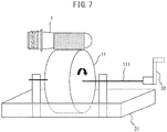
- FIG. 5 is a schematic perspective view of the die coater 13. As shown in FIG. 5 , the die coater 13 is formed with an elongated slot 131. The coating solution is discharged in a sheet shape from the elongated slot 131 to the outer circumferential surface of the transfer roller 11. Note that, the preform coating device 10 may be provided with another application device configured to apply the coating solution with a predetermined thickness to the outer circumferential surface of the transfer roller 11, instead of the die coater 13.
- Another method may also be considered as the method for supplying the coating solution to the outer circumferential surface of the transfer roller 11.
- the solution dipping tank 31 in which the coating solution is poured, below the transfer roller 11 and directly dip the transfer roller 11 in the coating solution.
- the coating solution is deposited on the outer circumferential surface of the transfer roller 11, then, if the outer circumferential surface of the transfer roller 11 rotates in contact with the outer circumferential surface of the preform 1, the coating solution is transferred from the outer circumferential surface of the transfer roller 11 to the outer circumferential surface of the preform 1.
- the coating solution draws air along with it and sometimes is formed with bubbles inside the solution dipping tank 31.
- the coating solution containing the bubbles 50 is supplied from the solution dipping tank 31 to the outer circumferential surface of the transfer roller 11 to be transferred to the outer circumferential surface of the preform 1, so the film thickness of the coating solution becomes uneven on the outer circumferential surface of the preform 1. This problem easily occurs in particular when using a high viscosity coating solution, since the bubbles are difficult to remove from the coating solution.
- the minimum extent of coating solution is constantly discharged from the elongated slot 131 of the die coater 13 directly to the outer circumferential surface of the transfer roller 11 so that the solution becomes a predetermined film thickness, so bubbles do not easily form in the coating solution. Therefore, it is possible to make the film thickness of the coating solution coated on the outer circumferential surface of the preform 1 uniformly thin and in turn reduce the occurrence of defects of the preform 1 or plastic bottle.
- the die coater 13 is connected through a first hose 16 to the pump 15.
- the pump 15 is connected through a second hose 17 to the solution holding tank 14.
- the pump 15 is preferably a non-pulsation pump.
- the solution holding tank 14 is filled with the desired coating solution before starting the coating. Further, as explained later, the coating solution not transferred to the outer circumferential surface of the preform 1 is returned to the solution holding tank 14 for reuse. If the amount of the coating solution inside the solution holding tank 14 becomes smaller than a predetermined amount, the coating solution is refilled in the solution holding tank 14.
- the mouth part 1a and bottom part 1c of the preform 1 are sufficiently low in gas barrier property even without the coating. Further, the bottom part 1c is easily abraded compared with other parts, so if a coating is formed on the bottom part 1c, the coating on the bottom part 1c is liable to crack.
- the coating solution for example, a polyvinyl alcohol (PVA) solution having a gas barrier property and a non-water soluble coating agent protecting this are used.
- PVA polyvinyl alcohol
- the outer circumferential surface of the preform 1 is first formed with the PVA coating, then is given the protective coating to cover the PVA coating.
- the problem can arise that since PVA is hydrophilic, if the protective coating of the bottom part 1c cracks, the exposed PVA coating will end up being redissolved in the water.
- the coating solution is preferably transferred from the outer circumferential surface of the transfer roller 11 to only the cylindrical body part 1b of the preform 1. Due to this, it is possible to shorten the drying time of the coating solution coated on the preform 1. Further, cylindrical body part 1b has a simple cylindrical shape, so the coating of the coating solution by the transfer roller 11 becomes easier than other parts.
- the preform coating device 10 further comprises a solution receiving tank 18 receiving the coating solution dropped from the transfer roller 11, a scraper 19 scraping off the coating solution not transferred to the outer circumferential surface of the preform 1 from the outer circumferential surface of the transfer roller 11, and a solution recovery tank 20 recovering the coating solution scraped off by the scraper 19.
- the scraper 19 contacts the transfer roller 11 over the entire axial direction of the transfer roller 11. Due to this, the majority of the coating solution not transferred to the outer circumferential surface of the preform 1 can be recovered. Further, the scraper 19 extends downward at a slant from the outer circumferential surface of the transfer roller 11 toward the solution recovery tank 20. Due to this, the coating solution scraped off by the scraper 19 flows into the solution recovery tank 20 by gravity. At this time, the coating solution draws air along with it and sometimes is formed with bubbles inside the solution recovery tank 20.
- the preform coating device 10 further comprises a defoaming device 21 removing bubbles from the recovered coating solution.
- the defoaming device 21 is connected through a first pipe 22 to the solution recovery tank 20 and through a second pipe 23 to the solution holding tank 14.
- the defoaming device 21 removes the bubbles 50 formed in the solution recovery tank 20.
- the defoamed coating solution is returned to the solution holding tank 14 and is again supplied by the pump 15 to the die coater 13.
- the injection molding method or PCM method is used to form a preform 1 from a resin.
- the coating solution is applied to the outer circumferential surface of the formed preform 1.
- the surface treatment is, for example, plasma treatment, corona treatment, or electron beam treatment.
- the coating solution is applied by discharging the coating solution from a slot 131 of the die coater 13 to the outer circumferential surface of the columnar shaped transfer roller 11 rotating about its center axis 111 and by conveying the preform 1 on the outer circumferential surface of the transfer roller 11 and transferring the coating solution from the outer circumferential surface of the transfer roller 11 to the outer circumferential surface of the preform 1.
- the coating solution not transferred to the outer circumferential surface of the preform 1 is recovered by the scraper 19. After that, the recovered coating solution is cleared of bubbles by the defoaming device 21 and again discharged to the outer circumferential surface of the transfer roller 11 from the slot 131 of the die coater 13.
- the coating solution may be supplied on the outer circumferential surface of the transfer roller 11 by another application device configured to apply the coating solution with a predetermined thickness to the outer circumferential surface of the transfer roller 11, instead of the die coater 13.
- the coating solution is preferably transferred from the outer circumferential surface of the transfer roller 11 to only the cylindrical body part 1b of the preform 1.
- the circumferential direction length of the transfer roller 11 at the part contacting the preform 1 is the circumferential direction length of the preform 1 or more.
- Preforms 1 can be continuously conveyed by the conveyor device 12 on the outer circumferential surface of the transfer roller 11. Due to this, it is possible to efficiently apply a coating solution over the entire circumference of the outer circumferential surfaces of a plurality of preforms 1.
- the outer circumferential surface of the preform 1 is made to dry on the conveyor device 12.
- the drying is performed in two stages. In the first stage, the preform 1 is rapidly heated by a carbon heater. In the second stage, the preform 1 is dried by hot air by a far infrared ray heater to be held in temperature. As a result, a coating is formed on the outer circumferential surface of the preform 1.
- the coating solution for example, a PVA solution having a gas barrier property and a non-water soluble coating agent protecting this are used.
- the outer circumferential surface of the preform 1 is first formed with the PVA coating, then, to prevent the PVA coating from being exposed, is given the protective coating to cover the PVA coating.
- the double layer coating can be formed by using a single preform coating device 10 while changing the coating solutions or by using two preform coating devices 10.
- the non-water soluble coating agent protecting the PVA is, for example, a polyolefin dispersion solution, various modified polyolefin dispersion solutions, a polyvinyl butyral (PVB) solution, etc.
- the non-water soluble coating agent protecting the PVA is typically low in viscosity and applied thinner than the PVA solution, so the drying time is shorter than the PVA solution. For this reason, excessive heating seldom causes the preform 1 to whiten. Therefore, the non-water soluble coating agent protecting the PVA may be applied by dipping the preform 1 in the vertical direction like in the past.
- the bottom part 1c of the preform 1 can also be formed with a protective coating, but the PVA coating is not formed on the bottom part 1c, and therefore even if the protective coating of the bottom part 1c cracks, the problem of the hydrophilic PVA redissolving in water will not arise.
- the coating solution examples include a water-soluble polyamide, water-soluble polyester, polyvinylidene chloride (PVDC), polyacrylonitrile, ethylene-vinyl alcohol copolymer resin (EVOH), polyglycolic acid, and other solutions of barrier resins and mixed solutions of these with inorganic matter, oxide absorbents, etc., an epoxy-based, urethane-based, or phenol-based thermosetting binder, a hot melt resin or other thermoplastic binder, or a coating material like an aqueous ink or solvent-based ink.
- PVDC polyvinylidene chloride
- EVOH ethylene-vinyl alcohol copolymer resin
- glycolic acid polyglycolic acid
- barrier resins and mixed solutions of these with inorganic matter, oxide absorbents, etc. an epoxy-based, urethane-based, or phenol-based thermosetting binder, a hot melt resin or other thermoplastic binder, or a coating material like an aqueous ink or
- the viscosity of the coating solution used in the present embodiment is preferably 1 mPa ⁇ s or more, more preferably 100 mPa ⁇ s or more.
- the plastic bottle 3 is manufactured by stretch blow molding a preform 1 manufactured by the above method.
Landscapes
- Engineering & Computer Science (AREA)
- Mechanical Engineering (AREA)
- Manufacturing & Machinery (AREA)
- Life Sciences & Earth Sciences (AREA)
- Wood Science & Technology (AREA)
- Details Of Rigid Or Semi-Rigid Containers (AREA)
- Application Of Or Painting With Fluid Materials (AREA)
- Blow-Moulding Or Thermoforming Of Plastics Or The Like (AREA)
- Coating Apparatus (AREA)
- Containers Having Bodies Formed In One Piece (AREA)
Applications Claiming Priority (2)
| Application Number | Priority Date | Filing Date | Title |
|---|---|---|---|
| JP2014078114A JP2015199012A (ja) | 2014-04-04 | 2014-04-04 | プリフォームコーティング装置、プリフォームの製造方法及びプラスチックボトルの製造方法 |
| PCT/JP2015/060638 WO2015152408A1 (ja) | 2014-04-04 | 2015-04-03 | プリフォームコーティング装置、プリフォームの製造方法及びプラスチックボトルの製造方法 |
Publications (2)
| Publication Number | Publication Date |
|---|---|
| EP3127618A1 true EP3127618A1 (de) | 2017-02-08 |
| EP3127618A4 EP3127618A4 (de) | 2017-12-20 |
Family
ID=54240715
Family Applications (1)
| Application Number | Title | Priority Date | Filing Date |
|---|---|---|---|
| EP15773631.5A Withdrawn EP3127618A4 (de) | 2014-04-04 | 2015-04-03 | Vorformbeschichtungsvorrichtung, verfahren zur herstellung einer vorform und verfahren zur herstellung einer kunststoffflasche |
Country Status (8)
| Country | Link |
|---|---|
| US (1) | US20170136677A1 (de) |
| EP (1) | EP3127618A4 (de) |
| JP (1) | JP2015199012A (de) |
| CN (1) | CN106061626A (de) |
| AU (1) | AU2015242787A1 (de) |
| CA (1) | CA2942286A1 (de) |
| SG (1) | SG11201607420PA (de) |
| WO (1) | WO2015152408A1 (de) |
Families Citing this family (9)
| Publication number | Priority date | Publication date | Assignee | Title |
|---|---|---|---|---|
| ES2884873T3 (es) | 2015-09-30 | 2021-12-13 | Suntory Holdings Ltd | Dispositivo de revestimiento de preformas y método de revestimiento de preformas |
| US11839871B2 (en) | 2016-01-08 | 2023-12-12 | Johnson Matthey Public Limited Company | Method and apparatus for coating an end surface of a monolithic substrate |
| CN111491742B (zh) * | 2017-12-25 | 2022-07-08 | 三得利控股株式会社 | 预制件涂敷装置 |
| EP3733301A4 (de) * | 2017-12-25 | 2021-09-01 | Suntory Holdings Limited | Vorformbeschichtungsvorrichtung |
| US11511310B2 (en) | 2017-12-25 | 2022-11-29 | Suntory Holdings Limited | Preform coating device |
| JP7016888B2 (ja) * | 2017-12-25 | 2022-02-07 | サントリーホールディングス株式会社 | プリフォームコーティング装置 |
| AU2019266763A1 (en) * | 2018-05-10 | 2020-11-26 | Suntory Holdings Limited | Method for coating preform for plastic bottle |
| US20230129901A1 (en) * | 2021-10-21 | 2023-04-27 | Gerhard Designing & Manufacturing Inc. | Excess coating removal device for can coating machines |
| CN116408236B (zh) * | 2022-07-26 | 2025-07-18 | 荆州恒隆汽车零部件制造有限公司 | 一种转向器减震套橡胶油的滚涂装置及方法 |
Family Cites Families (12)
| Publication number | Priority date | Publication date | Assignee | Title |
|---|---|---|---|---|
| US3677801A (en) * | 1970-07-28 | 1972-07-18 | Dart Ind Inc | Method of coating irregular objects |
| JPS58906B2 (ja) * | 1979-04-09 | 1983-01-08 | 麒麟麦酒株式会社 | 壜等の塗布装置 |
| IE72977B1 (en) * | 1990-07-04 | 1997-05-07 | John W Cahill | A process for molding a multiple layer structure and a container made therefrom |
| JPH0611863U (ja) * | 1992-07-08 | 1994-02-15 | 大日本スクリーン製造株式会社 | ロールコータ |
| JPH09192568A (ja) * | 1996-01-22 | 1997-07-29 | Chugai Ro Co Ltd | ダイコータへの塗料供給装置 |
| US6309692B1 (en) * | 1996-01-22 | 2001-10-30 | Chugai Ro Co., Ltd. | Method of and apparatus for coating a substrate with a coating material having an even thickness |
| DE102004036275B4 (de) * | 2004-07-27 | 2016-10-20 | Krones Aktiengesellschaft | Vorrichtung und Verfahren zum Beschichten |
| MX2009008201A (es) * | 2007-01-31 | 2009-08-12 | Alpla Werke | Metodo para recubrir cuerpos huecos en ciertas regiones. |
| JP2012250190A (ja) * | 2011-06-03 | 2012-12-20 | Hirano Tecseed Co Ltd | 塗工装置 |
| EP2532600B1 (de) * | 2011-06-06 | 2020-01-22 | Kuraray Europe GmbH | Kunststoffbehälter mit gasbarrierebeschichtung und optionaler wasserabweisender innenbeschichtung |
| JP6037879B2 (ja) * | 2013-02-13 | 2016-12-07 | サントリーホールディングス株式会社 | ガスバリアコーティングを有するプラスチックボトル用プリフォーム |
| CN103660103B (zh) * | 2013-12-12 | 2016-08-24 | 上海交通大学 | 基于带状模具的薄膜双面微结构卷对卷uv固化成型装置 |
-
2014
- 2014-04-04 JP JP2014078114A patent/JP2015199012A/ja active Pending
-
2015
- 2015-04-03 AU AU2015242787A patent/AU2015242787A1/en not_active Abandoned
- 2015-04-03 EP EP15773631.5A patent/EP3127618A4/de not_active Withdrawn
- 2015-04-03 CA CA2942286A patent/CA2942286A1/en not_active Abandoned
- 2015-04-03 WO PCT/JP2015/060638 patent/WO2015152408A1/ja not_active Ceased
- 2015-04-03 US US15/300,027 patent/US20170136677A1/en not_active Abandoned
- 2015-04-03 SG SG11201607420PA patent/SG11201607420PA/en unknown
- 2015-04-03 CN CN201580012409.8A patent/CN106061626A/zh active Pending
Also Published As
| Publication number | Publication date |
|---|---|
| US20170136677A1 (en) | 2017-05-18 |
| SG11201607420PA (en) | 2016-10-28 |
| EP3127618A4 (de) | 2017-12-20 |
| CA2942286A1 (en) | 2015-10-08 |
| WO2015152408A1 (ja) | 2015-10-08 |
| AU2015242787A1 (en) | 2016-10-06 |
| JP2015199012A (ja) | 2015-11-12 |
| CN106061626A (zh) | 2016-10-26 |
Similar Documents
| Publication | Publication Date | Title |
|---|---|---|
| EP3127618A1 (de) | Vorformbeschichtungsvorrichtung, verfahren zur herstellung einer vorform und verfahren zur herstellung einer kunststoffflasche | |
| CN108025330B (zh) | 预塑件涂敷装置及预塑件涂敷方法 | |
| KR101898913B1 (ko) | 적층박리용기의 제조 방법, 적층박리용기의 에어 리크 검사 방법 | |
| EP1896245B2 (de) | Verfahren zur sterilisation von vorformlingen und anlage zur herstellung von sterilen körpers aus diesen vorformlingen | |
| JP6537429B2 (ja) | プリフォームコーティング装置 | |
| EP2522772A1 (de) | Behälter | |
| JP6037879B2 (ja) | ガスバリアコーティングを有するプラスチックボトル用プリフォーム | |
| CN108137183B (zh) | 旋转式热收缩标签纸附着装置 | |
| JP6537426B2 (ja) | プリフォームコーティング装置及びプリフォームコーティング方法 | |
| US20100244298A1 (en) | Device for transporting a hollow body, installation provided with such devices, and method for conveying a hollow body attached to such a device | |
| WO2018185015A1 (fr) | Installation de traitement de recipients et procede de changement de format | |
| JP4335041B2 (ja) | プリフォームの加熱方法 | |
| US20150158204A1 (en) | Method and apparatus for producing plastic preforms | |
| EP4261006B1 (de) | Zieh- und kühlstab zur herstellung von behältern | |
| JP6628535B2 (ja) | プリフォームのコーティング方法 | |
| CN111372691B (zh) | 预制件涂敷装置 | |
| FR3048633A1 (fr) | Procede de fabrication d'une preforme pour la production d'une bouteille a bouchage en liege, preforme obtenue | |
| JPH11309785A (ja) | プラスチックチューブ容器の製造方法および装置 | |
| NZ741019B2 (en) | Preform coating device and preform coating method | |
| JP2015139979A (ja) | ブロー成形方法 |
Legal Events
| Date | Code | Title | Description |
|---|---|---|---|
| PUAI | Public reference made under article 153(3) epc to a published international application that has entered the european phase |
Free format text: ORIGINAL CODE: 0009012 |
|
| 17P | Request for examination filed |
Effective date: 20160916 |
|
| AK | Designated contracting states |
Kind code of ref document: A1 Designated state(s): AL AT BE BG CH CY CZ DE DK EE ES FI FR GB GR HR HU IE IS IT LI LT LU LV MC MK MT NL NO PL PT RO RS SE SI SK SM TR |
|
| AX | Request for extension of the european patent |
Extension state: BA ME |
|
| DAV | Request for validation of the european patent (deleted) | ||
| DAX | Request for extension of the european patent (deleted) | ||
| A4 | Supplementary search report drawn up and despatched |
Effective date: 20171121 |
|
| RIC1 | Information provided on ipc code assigned before grant |
Ipc: B29B 11/14 20060101ALI20171114BHEP Ipc: B65D 1/00 20060101ALI20171114BHEP Ipc: B05D 1/28 20060101ALI20171114BHEP Ipc: B05D 7/02 20060101ALI20171114BHEP Ipc: B29C 49/02 20060101ALI20171114BHEP Ipc: B05C 1/02 20060101AFI20171114BHEP |
|
| STAA | Information on the status of an ep patent application or granted ep patent |
Free format text: STATUS: THE APPLICATION IS DEEMED TO BE WITHDRAWN |
|
| 18D | Application deemed to be withdrawn |
Effective date: 20180619 |