EP3128667A2 - Steuerungsverfahren zum anlassen eines elektrischen synchronmotors - Google Patents
Steuerungsverfahren zum anlassen eines elektrischen synchronmotors Download PDFInfo
- Publication number
- EP3128667A2 EP3128667A2 EP16172900.9A EP16172900A EP3128667A2 EP 3128667 A2 EP3128667 A2 EP 3128667A2 EP 16172900 A EP16172900 A EP 16172900A EP 3128667 A2 EP3128667 A2 EP 3128667A2
- Authority
- EP
- European Patent Office
- Prior art keywords
- current
- speed
- voltage
- module
- determining
- Prior art date
- Legal status (The legal status is an assumption and is not a legal conclusion. Google has not performed a legal analysis and makes no representation as to the accuracy of the status listed.)
- Granted
Links
Images

Classifications
-
- H—ELECTRICITY
- H02—GENERATION; CONVERSION OR DISTRIBUTION OF ELECTRIC POWER
- H02P—CONTROL OR REGULATION OF ELECTRIC MOTORS, ELECTRIC GENERATORS OR DYNAMO-ELECTRIC CONVERTERS; CONTROLLING TRANSFORMERS, REACTORS OR CHOKE COILS
- H02P1/00—Arrangements for starting electric motors or dynamo-electric converters
- H02P1/16—Arrangements for starting electric motors or dynamo-electric converters for starting dynamo-electric motors or dynamo-electric converters
- H02P1/46—Arrangements for starting electric motors or dynamo-electric converters for starting dynamo-electric motors or dynamo-electric converters for starting an individual synchronous motor
- H02P1/52—Arrangements for starting electric motors or dynamo-electric converters for starting dynamo-electric motors or dynamo-electric converters for starting an individual synchronous motor by progressive increase of frequency of supply to motor
-
- H—ELECTRICITY
- H02—GENERATION; CONVERSION OR DISTRIBUTION OF ELECTRIC POWER
- H02P—CONTROL OR REGULATION OF ELECTRIC MOTORS, ELECTRIC GENERATORS OR DYNAMO-ELECTRIC CONVERTERS; CONTROLLING TRANSFORMERS, REACTORS OR CHOKE COILS
- H02P1/00—Arrangements for starting electric motors or dynamo-electric converters
- H02P1/16—Arrangements for starting electric motors or dynamo-electric converters for starting dynamo-electric motors or dynamo-electric converters
- H02P1/46—Arrangements for starting electric motors or dynamo-electric converters for starting dynamo-electric motors or dynamo-electric converters for starting an individual synchronous motor
-
- H—ELECTRICITY
- H02—GENERATION; CONVERSION OR DISTRIBUTION OF ELECTRIC POWER
- H02P—CONTROL OR REGULATION OF ELECTRIC MOTORS, ELECTRIC GENERATORS OR DYNAMO-ELECTRIC CONVERTERS; CONTROLLING TRANSFORMERS, REACTORS OR CHOKE COILS
- H02P21/00—Arrangements or methods for the control of electric machines by vector control, e.g. by control of field orientation
- H02P21/34—Arrangements for starting
-
- H—ELECTRICITY
- H02—GENERATION; CONVERSION OR DISTRIBUTION OF ELECTRIC POWER
- H02P—CONTROL OR REGULATION OF ELECTRIC MOTORS, ELECTRIC GENERATORS OR DYNAMO-ELECTRIC CONVERTERS; CONTROLLING TRANSFORMERS, REACTORS OR CHOKE COILS
- H02P6/00—Arrangements for controlling synchronous motors or other dynamo-electric motors using electronic commutation dependent on the rotor position; Electronic commutators therefor
- H02P6/14—Electronic commutators
- H02P6/16—Circuit arrangements for detecting position
- H02P6/18—Circuit arrangements for detecting position without separate position detecting elements
- H02P6/181—Circuit arrangements for detecting position without separate position detecting elements using different methods depending on the speed
-
- H—ELECTRICITY
- H02—GENERATION; CONVERSION OR DISTRIBUTION OF ELECTRIC POWER
- H02P—CONTROL OR REGULATION OF ELECTRIC MOTORS, ELECTRIC GENERATORS OR DYNAMO-ELECTRIC CONVERTERS; CONTROLLING TRANSFORMERS, REACTORS OR CHOKE COILS
- H02P6/00—Arrangements for controlling synchronous motors or other dynamo-electric motors using electronic commutation dependent on the rotor position; Electronic commutators therefor
- H02P6/20—Arrangements for starting
-
- H—ELECTRICITY
- H02—GENERATION; CONVERSION OR DISTRIBUTION OF ELECTRIC POWER
- H02P—CONTROL OR REGULATION OF ELECTRIC MOTORS, ELECTRIC GENERATORS OR DYNAMO-ELECTRIC CONVERTERS; CONTROLLING TRANSFORMERS, REACTORS OR CHOKE COILS
- H02P2203/00—Indexing scheme relating to controlling arrangements characterised by the means for detecting the position of the rotor
- H02P2203/09—Motor speed determination based on the current and/or voltage without using a tachogenerator or a physical encoder
Definitions
- the present invention relates to a control method implemented in a variable speed drive for starting an electric motor connected to said variable speed drive.
- the control method applies to starting a synchronous electric motor and allows to align the rotor of this motor with a reference position.
- a variable speed drive comprises a rectifier module which supplies a DC voltage from an external AC supply network and an inverter (or chopper) module.
- This inverter module comprises power semiconductor electronic components for chopping the continuous voltage in Pulse Width Modulation PWM (PWM), so as to output a pulsed variable voltage voltage via a power cable. a variable frequency of rotation to the motor.
- PWM Pulse Width Modulation
- a drive controller controls conduction and blocking of the semiconductor components at the sampling rate to control the PWM motor with an appropriate variable voltage.
- a closed-loop speed controller for controlling a permanent magnet synchronous motor generally uses an absolute position sensor of the rotor.
- this type of sensor has a particularly high cost and reliability problems (need for additional cable, sensitivity to electromagnetic noise ). It is therefore known from the document JP1060287 to use an incremental encoder to know the relative position of the rotor. However the use of an incremental encoder requires knowing the initial position of the rotor.
- the document US 7,202,618 proposes a solution that is implemented in a variable speed drive to determine the initial position of the rotor in a three-phase electric motor.
- This solution consists of sending voltage pulses on each of the phases of the motor for a determined period of time and determining the peaks of currents having circulated in the phases of the motor. Then, by comparison between the currents obtained for each phase and from relations between the currents, the initial position of the rotor can be obtained without calculation.
- stored tables can determine without calculation the initial position of the rotor.
- the initial position of the rotor is certainly obtained without calculation but the various proposed solutions are complex and long to implement at each engine start.
- these methods are based on motor side effects (magnetic saturation, saliency ). However, there are engines that do not have enough saliency and others where the magnetic saturation does not have the expected effect. These prior methods may therefore fail.
- the object of the invention is to provide a method of controlling a synchronous electric motor that allows a simple, reliable and unrestrained alignment of the rotor in terms of alignment time and torque applied at startup. This process is based on the fundamental motor model and does not use side or non-linear effects. Thus it is robust and applicable to all types of synchronous motors (with magnet inside the rotor - IPM, with magnet on the surface of the rotor - SPM or variable reluctance motor - SynRM).
- the step of determining the voltage in the rotating marker is performed without control of the current by applying a U / F type control law.
- the module for determining the voltage in the rotating marker is implemented without control of the current by applying a U / F type control law.
- the solution does not consist in a determination of the initial angle of the rotor as is often the case in the solutions of the state of the art. In the present invention, it is indeed about determining a command to align the rotor at a selected reference position and defined by the reference velocity path applied at the input.
- the control method of the invention is implemented in a variable speed drive for starting a synchronous electric motor.
- the control method applies for any synchronous electric motor, for example variable reluctance type, permanent magnet smooth or salient, ...
- variable speed drive is connected upstream to an electrical distribution network N by three input phases R, S, T.
- the variable speed drive comprises an input stage consisting of a rectifier REC, by example of diode bridge type, arranged to rectify the AC voltage supplied by the network N.
- the variable speed drive also comprises a DC supply bus connected to the rectifier and comprising two power supply lines interconnected by one or more capacitors of bus.
- the frequency converter also comprises an output stage composed of an INV inverter receiving a DC voltage supplied by the DC supply bus and controlled to provide variable voltages at output to the synchronous electric motor M, in three output phases a, b, c.
- the control unit UC of the variable speed drive implements a main control law L for controlling the inverter and determining the output voltages necessary for the operation of the electric motor M (block B1 on the figure 2 ).
- this main control law L has as input a reference speed ⁇ ref from which it determines a reference torque current (not shown). It also receives as input a reference flow current Idref. From the reference torque current and the reference flow current and the measurements or estimates of the flow current Id and the torque current Iq, it determines reference voltages Vdref, Vqref from which the single voltages Va are determined. , Vb, Vc to be applied on each output phase (block B2).
- the position of the rotor is unknown to the control unit UC of the variable speed drive preventing the implementation of the main control law L.
- a specific sequence is implemented to align the rotor at a known position.
- the control method of the invention makes it possible to create a start sequence (ST, figure 2 ) in rotation of the engine. For starting the synchronous electric motor, the control method of the invention thus replaces the main control law L.
- the control method can determine (block B7) the voltages to be applied to the three output phases in order to allow the alignment of the rotor to a known position.
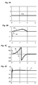
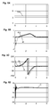
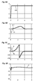
- FIGS. 4A to 4D, 5A to 5D and 6A to 6D illustrate simulation results for different cases of operation.
- the voltage Vdq generated follows a constant ( Figure 4A ) and the reference speed follows a predefined class C0 profile ( Figure 4B ).
- the figure 4C shows that the actual position of the rotor reaches the reference position at the end of the start-up process.
- the figure 4D shows that the torque C remains constant and that the startup process used does not generate jerks on the engine.
- the generated Vdq voltage follows a non-constant but continuous trajectory ( Figure 6A ) and the reference speed follows a predefined class C1 profile ( Figure 6B ).
- Figure 6C shows that the actual position of the rotor reaches the reference position at the end of the start-up process.
- the Figure 6D shows that the torque C remains constant and that the startup process used does not generate jerks on the engine.
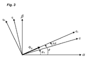
- the determined reference position ⁇ s on which the rotor is aligned aligns directly with the actual position ⁇ of the rotor (block B8), which may be useful in the control in normal operation of the motor.
- the motor control is done via the input voltage and u dq and the reference speed ⁇ s .
- the system is stable if the three coefficients 1, fn p J M and 3 not p 2 ⁇ M I 2 J M cos ⁇ - ⁇ ⁇ eq are positive.
Landscapes
- Engineering & Computer Science (AREA)
- Power Engineering (AREA)
- Control Of Motors That Do Not Use Commutators (AREA)
- Control Of Ac Motors In General (AREA)
Applications Claiming Priority (1)
| Application Number | Priority Date | Filing Date | Title |
|---|---|---|---|
| FR1556191A FR3038469B1 (fr) | 2015-07-01 | 2015-07-01 | Procede de commande pour le demarrage d'un moteur electrique synchrone |
Publications (3)
| Publication Number | Publication Date |
|---|---|
| EP3128667A2 true EP3128667A2 (de) | 2017-02-08 |
| EP3128667A3 EP3128667A3 (de) | 2017-05-17 |
| EP3128667B1 EP3128667B1 (de) | 2024-02-28 |
Family
ID=54199829
Family Applications (1)
| Application Number | Title | Priority Date | Filing Date |
|---|---|---|---|
| EP16172900.9A Active EP3128667B1 (de) | 2015-07-01 | 2016-06-03 | Steuerungsverfahren zum anlassen eines elektrischen synchronmotors |
Country Status (5)
| Country | Link |
|---|---|
| US (1) | US10205411B2 (de) |
| EP (1) | EP3128667B1 (de) |
| CN (1) | CN106452226B (de) |
| ES (1) | ES2979075T3 (de) |
| FR (1) | FR3038469B1 (de) |
Citations (3)
| Publication number | Priority date | Publication date | Assignee | Title |
|---|---|---|---|---|
| JPH1060287A (ja) | 1996-08-14 | 1998-03-03 | Matsushita Electric Works Ltd | 高熱伝導性材料及びその製造方法、床暖房システム |
| EP1213828A1 (de) | 1999-09-17 | 2002-06-12 | Kabushiki Kaisha Yaskawa Denki | Vorrichtung zur abschäbung der aufangsmagne tisierung der pole eines synchronmotors |
| US7202618B2 (en) | 2004-12-06 | 2007-04-10 | Kabushiki Kaisha Toyota Jidoshokki | Inverter device |
Family Cites Families (10)
| Publication number | Priority date | Publication date | Assignee | Title |
|---|---|---|---|---|
| US5998957A (en) * | 1997-04-29 | 1999-12-07 | Satcon Technology Corporation | Dissipativity-based controller for synchronous electric drives, and associated methods |
| US5929400A (en) * | 1997-12-22 | 1999-07-27 | Otis Elevator Company | Self commissioning controller for field-oriented elevator motor/drive system |
| JP4665360B2 (ja) * | 2001-08-06 | 2011-04-06 | 株式会社安川電機 | 電動機制御装置 |
| JP4158101B2 (ja) * | 2003-03-19 | 2008-10-01 | 日本パルスモーター株式会社 | モータ制御用パルス発生ic |
| JP4901517B2 (ja) * | 2007-02-08 | 2012-03-21 | 株式会社東芝 | 交流電動機制御装置 |
| JP5547866B2 (ja) * | 2007-06-19 | 2014-07-16 | 株式会社日立産機システム | 誘導電動機駆動装置、電動機駆動システム、及び昇降システム |
| US8115441B2 (en) * | 2007-07-19 | 2012-02-14 | Hamilton Sundstrand Corporation | On-line measurement of an induction machine's rotor time constant by small signal d-axis current injection |
| FR2944659B1 (fr) * | 2009-04-21 | 2011-04-01 | Schneider Toshiba Inverter | Procede de determination de la position du vecteur de flux d'un moteur |
| GB201012321D0 (en) * | 2010-07-22 | 2010-09-08 | Artificial Lift Co Ltd | Control of a brushless dc motor over a long cable in a well |
| FR2972583B1 (fr) * | 2011-03-11 | 2013-03-01 | Schneider Toshiba Inverter | Procede de commande mis en oeuvre dans un convertisseur de puissance pour identifier des parametres lies a la saturation magnetique d'un moteur electrique |
-
2015
- 2015-07-01 FR FR1556191A patent/FR3038469B1/fr not_active Expired - Fee Related
-
2016
- 2016-06-03 EP EP16172900.9A patent/EP3128667B1/de active Active
- 2016-06-03 ES ES16172900T patent/ES2979075T3/es active Active
- 2016-06-08 US US15/176,735 patent/US10205411B2/en active Active
- 2016-07-01 CN CN201610515585.XA patent/CN106452226B/zh active Active
Patent Citations (3)
| Publication number | Priority date | Publication date | Assignee | Title |
|---|---|---|---|---|
| JPH1060287A (ja) | 1996-08-14 | 1998-03-03 | Matsushita Electric Works Ltd | 高熱伝導性材料及びその製造方法、床暖房システム |
| EP1213828A1 (de) | 1999-09-17 | 2002-06-12 | Kabushiki Kaisha Yaskawa Denki | Vorrichtung zur abschäbung der aufangsmagne tisierung der pole eines synchronmotors |
| US7202618B2 (en) | 2004-12-06 | 2007-04-10 | Kabushiki Kaisha Toyota Jidoshokki | Inverter device |
Also Published As
| Publication number | Publication date |
|---|---|
| CN106452226B (zh) | 2019-06-07 |
| EP3128667A3 (de) | 2017-05-17 |
| FR3038469A1 (fr) | 2017-01-06 |
| EP3128667B1 (de) | 2024-02-28 |
| ES2979075T3 (es) | 2024-09-24 |
| FR3038469B1 (fr) | 2017-06-23 |
| CN106452226A (zh) | 2017-02-22 |
| US10205411B2 (en) | 2019-02-12 |
| US20170005597A1 (en) | 2017-01-05 |
Similar Documents
| Publication | Publication Date | Title |
|---|---|---|
| EP2684289B1 (de) | In einem stromwandler implementiertes steuerverfahren zur identifizierung von parametern in bezug auf die magnetische sättigung eines elektromotors | |
| EP2246973B1 (de) | Verfahren zur Positionsbestimmung des Flussvektors eines Motors | |
| EP2294688B1 (de) | Verfahren zur bestimmung der induktanzen einer permanentmagnet-synchronmaschine | |
| EP3157158A1 (de) | Steuerverfahren zum identifizieren der induktanzwerte eines synchronen elektromotors mit variabler reluktanz | |
| WO2013178906A1 (fr) | Procede de commande du couple electromagnetique d'une machine synchrone a haute vitesse | |
| EP3229366B1 (de) | Steuerungsverfahren eines asynchronen elektromotors | |
| EP3401694B1 (de) | Identifizierungsverfahren des elektrischen widerstands eines rotors eines elektromotors | |
| EP3451525A1 (de) | Verfahren zur identifizierung der magnetischen sättigungsparameter eines asynchronen elektromotors | |
| EP2963802B1 (de) | Steuerungsverfahren zum anlassen eines elektrischen synchronmotors | |
| EP3503380B1 (de) | Steuerverfahren eines elektromotors, das eine identifizierungssequenz eines transformators umfasst | |
| EP2810367A1 (de) | Steuerung einer elektrischen permanentmagnetmaschine | |
| EP3128667B1 (de) | Steuerungsverfahren zum anlassen eines elektrischen synchronmotors | |
| EP3005548B1 (de) | Verfahren zur steuerung einer elektrischen synchronmaschine, entsprechendes system und kraftfahrzeug mit dem system | |
| EP1484835A2 (de) | Verfahren und System zum Steuern des augenblickligen elektromagnetischen Drehmoments, und Datenträger zum Durchführen des Verfahrens | |
| EP4466785B1 (de) | Vorrichtung und verfahren zur steuerung einer synchronmaschine und zur rotorpositionsschätzung von inbetriebnahme auf eine vorbestimmte niedrige geschwindigkeit | |
| FR3115425A1 (fr) | Procédé et système de contrôle d’une machine électrique déterminant des consignes de courant optimales | |
| EP4423900A1 (de) | Verfahren zum automatischen einstellen eines drehwinkelsensors | |
| EP3175544B1 (de) | Verfahren und vorrichtung zur steuerung des elektromagnetischen drehmoments eines antriebsstranges | |
| EP4454119B1 (de) | Verfahren und system zur steuerung einer elektrischen maschine, die von einem wechselrichter mit mehreren schaltarmen angetrieben wird | |
| EP1727272B1 (de) | Verfahren und Vorrichtung zur Deadbeat-Steuerung einer Asynchronmaschine, Speichermedium für dieses Verfahren | |
| EP3012962A1 (de) | Steuerungsverfahren einer synchronlaufenden drehstrom-elektromaschine mit schleifringläufer | |
| EP3117516A2 (de) | Verfahren und system zur steuerung eines dreiphasigen elektromotors eines kraftfahrzeugs | |
| FR3036556A1 (fr) | Procede et systeme de commande d'une machine electrique asynchrone pour vehicule automobile. | |
| FR3073691A1 (fr) | Procede de commande d'une machine electrique synchrone |
Legal Events
| Date | Code | Title | Description |
|---|---|---|---|
| PUAI | Public reference made under article 153(3) epc to a published international application that has entered the european phase |
Free format text: ORIGINAL CODE: 0009012 |
|
| STAA | Information on the status of an ep patent application or granted ep patent |
Free format text: STATUS: THE APPLICATION HAS BEEN PUBLISHED |
|
| AK | Designated contracting states |
Kind code of ref document: A2 Designated state(s): AL AT BE BG CH CY CZ DE DK EE ES FI FR GB GR HR HU IE IS IT LI LT LU LV MC MK MT NL NO PL PT RO RS SE SI SK SM TR |
|
| AX | Request for extension of the european patent |
Extension state: BA ME |
|
| PUAL | Search report despatched |
Free format text: ORIGINAL CODE: 0009013 |
|
| AK | Designated contracting states |
Kind code of ref document: A3 Designated state(s): AL AT BE BG CH CY CZ DE DK EE ES FI FR GB GR HR HU IE IS IT LI LT LU LV MC MK MT NL NO PL PT RO RS SE SI SK SM TR |
|
| AX | Request for extension of the european patent |
Extension state: BA ME |
|
| RIC1 | Information provided on ipc code assigned before grant |
Ipc: H02P 1/46 20060101AFI20170413BHEP Ipc: H02P 21/00 20160101ALI20170413BHEP Ipc: H02P 1/52 20060101ALI20170413BHEP Ipc: H02P 6/20 20160101ALI20170413BHEP |
|
| STAA | Information on the status of an ep patent application or granted ep patent |
Free format text: STATUS: REQUEST FOR EXAMINATION WAS MADE |
|
| 17P | Request for examination filed |
Effective date: 20170530 |
|
| RBV | Designated contracting states (corrected) |
Designated state(s): AL AT BE BG CH CY CZ DE DK EE ES FI FR GB GR HR HU IE IS IT LI LT LU LV MC MK MT NL NO PL PT RO RS SE SI SK SM TR |
|
| REG | Reference to a national code |
Ref country code: DE Ref legal event code: R079 Free format text: PREVIOUS MAIN CLASS: H02P0001460000 Ipc: H02P0021340000 |
|
| RIC1 | Information provided on ipc code assigned before grant |
Ipc: H02P 21/00 20160101ALI20180928BHEP Ipc: H02P 1/46 20060101ALI20180928BHEP Ipc: H02P 1/52 20060101ALI20180928BHEP Ipc: H02P 21/34 20160101AFI20180928BHEP Ipc: H02P 6/20 20160101ALI20180928BHEP |
|
| STAA | Information on the status of an ep patent application or granted ep patent |
Free format text: STATUS: EXAMINATION IS IN PROGRESS |
|
| 17Q | First examination report despatched |
Effective date: 20181115 |
|
| GRAP | Despatch of communication of intention to grant a patent |
Free format text: ORIGINAL CODE: EPIDOSNIGR1 |
|
| STAA | Information on the status of an ep patent application or granted ep patent |
Free format text: STATUS: GRANT OF PATENT IS INTENDED |
|
| INTG | Intention to grant announced |
Effective date: 20230703 |
|
| GRAJ | Information related to disapproval of communication of intention to grant by the applicant or resumption of examination proceedings by the epo deleted |
Free format text: ORIGINAL CODE: EPIDOSDIGR1 |
|
| STAA | Information on the status of an ep patent application or granted ep patent |
Free format text: STATUS: EXAMINATION IS IN PROGRESS |
|
| GRAP | Despatch of communication of intention to grant a patent |
Free format text: ORIGINAL CODE: EPIDOSNIGR1 |
|
| STAA | Information on the status of an ep patent application or granted ep patent |
Free format text: STATUS: GRANT OF PATENT IS INTENDED |
|
| INTC | Intention to grant announced (deleted) | ||
| INTG | Intention to grant announced |
Effective date: 20230928 |
|
| GRAS | Grant fee paid |
Free format text: ORIGINAL CODE: EPIDOSNIGR3 |
|
| GRAA | (expected) grant |
Free format text: ORIGINAL CODE: 0009210 |
|
| STAA | Information on the status of an ep patent application or granted ep patent |
Free format text: STATUS: THE PATENT HAS BEEN GRANTED |
|
| AK | Designated contracting states |
Kind code of ref document: B1 Designated state(s): AL AT BE BG CH CY CZ DE DK EE ES FI FR GB GR HR HU IE IS IT LI LT LU LV MC MK MT NL NO PL PT RO RS SE SI SK SM TR |
|
| REG | Reference to a national code |
Ref country code: GB Ref legal event code: FG4D Free format text: NOT ENGLISH |
|
| REG | Reference to a national code |
Ref country code: CH Ref legal event code: EP |
|
| REG | Reference to a national code |
Ref country code: DE Ref legal event code: R096 Ref document number: 602016085982 Country of ref document: DE |
|
| REG | Reference to a national code |
Ref country code: IE Ref legal event code: FG4D Free format text: LANGUAGE OF EP DOCUMENT: FRENCH |
|
| REG | Reference to a national code |
Ref country code: LT Ref legal event code: MG9D |
|
| PG25 | Lapsed in a contracting state [announced via postgrant information from national office to epo] |
Ref country code: IS Free format text: LAPSE BECAUSE OF FAILURE TO SUBMIT A TRANSLATION OF THE DESCRIPTION OR TO PAY THE FEE WITHIN THE PRESCRIBED TIME-LIMIT Effective date: 20240628 |
|
| REG | Reference to a national code |
Ref country code: NL Ref legal event code: MP Effective date: 20240228 |
|
| PG25 | Lapsed in a contracting state [announced via postgrant information from national office to epo] |
Ref country code: LT Free format text: LAPSE BECAUSE OF FAILURE TO SUBMIT A TRANSLATION OF THE DESCRIPTION OR TO PAY THE FEE WITHIN THE PRESCRIBED TIME-LIMIT Effective date: 20240228 |
|
| PG25 | Lapsed in a contracting state [announced via postgrant information from national office to epo] |
Ref country code: GR Free format text: LAPSE BECAUSE OF FAILURE TO SUBMIT A TRANSLATION OF THE DESCRIPTION OR TO PAY THE FEE WITHIN THE PRESCRIBED TIME-LIMIT Effective date: 20240529 |
|
| PG25 | Lapsed in a contracting state [announced via postgrant information from national office to epo] |
Ref country code: RS Free format text: LAPSE BECAUSE OF FAILURE TO SUBMIT A TRANSLATION OF THE DESCRIPTION OR TO PAY THE FEE WITHIN THE PRESCRIBED TIME-LIMIT Effective date: 20240528 Ref country code: HR Free format text: LAPSE BECAUSE OF FAILURE TO SUBMIT A TRANSLATION OF THE DESCRIPTION OR TO PAY THE FEE WITHIN THE PRESCRIBED TIME-LIMIT Effective date: 20240228 Ref country code: NL Free format text: LAPSE BECAUSE OF FAILURE TO SUBMIT A TRANSLATION OF THE DESCRIPTION OR TO PAY THE FEE WITHIN THE PRESCRIBED TIME-LIMIT Effective date: 20240228 |
|
| PG25 | Lapsed in a contracting state [announced via postgrant information from national office to epo] |
Ref country code: RS Free format text: LAPSE BECAUSE OF FAILURE TO SUBMIT A TRANSLATION OF THE DESCRIPTION OR TO PAY THE FEE WITHIN THE PRESCRIBED TIME-LIMIT Effective date: 20240528 Ref country code: NO Free format text: LAPSE BECAUSE OF FAILURE TO SUBMIT A TRANSLATION OF THE DESCRIPTION OR TO PAY THE FEE WITHIN THE PRESCRIBED TIME-LIMIT Effective date: 20240528 Ref country code: NL Free format text: LAPSE BECAUSE OF FAILURE TO SUBMIT A TRANSLATION OF THE DESCRIPTION OR TO PAY THE FEE WITHIN THE PRESCRIBED TIME-LIMIT Effective date: 20240228 Ref country code: LT Free format text: LAPSE BECAUSE OF FAILURE TO SUBMIT A TRANSLATION OF THE DESCRIPTION OR TO PAY THE FEE WITHIN THE PRESCRIBED TIME-LIMIT Effective date: 20240228 Ref country code: IS Free format text: LAPSE BECAUSE OF FAILURE TO SUBMIT A TRANSLATION OF THE DESCRIPTION OR TO PAY THE FEE WITHIN THE PRESCRIBED TIME-LIMIT Effective date: 20240628 Ref country code: HR Free format text: LAPSE BECAUSE OF FAILURE TO SUBMIT A TRANSLATION OF THE DESCRIPTION OR TO PAY THE FEE WITHIN THE PRESCRIBED TIME-LIMIT Effective date: 20240228 Ref country code: GR Free format text: LAPSE BECAUSE OF FAILURE TO SUBMIT A TRANSLATION OF THE DESCRIPTION OR TO PAY THE FEE WITHIN THE PRESCRIBED TIME-LIMIT Effective date: 20240529 Ref country code: FI Free format text: LAPSE BECAUSE OF FAILURE TO SUBMIT A TRANSLATION OF THE DESCRIPTION OR TO PAY THE FEE WITHIN THE PRESCRIBED TIME-LIMIT Effective date: 20240228 Ref country code: BG Free format text: LAPSE BECAUSE OF FAILURE TO SUBMIT A TRANSLATION OF THE DESCRIPTION OR TO PAY THE FEE WITHIN THE PRESCRIBED TIME-LIMIT Effective date: 20240228 |
|
| PG25 | Lapsed in a contracting state [announced via postgrant information from national office to epo] |
Ref country code: PT Free format text: LAPSE BECAUSE OF FAILURE TO SUBMIT A TRANSLATION OF THE DESCRIPTION OR TO PAY THE FEE WITHIN THE PRESCRIBED TIME-LIMIT Effective date: 20240628 Ref country code: PL Free format text: LAPSE BECAUSE OF FAILURE TO SUBMIT A TRANSLATION OF THE DESCRIPTION OR TO PAY THE FEE WITHIN THE PRESCRIBED TIME-LIMIT Effective date: 20240228 |
|
| REG | Reference to a national code |
Ref country code: AT Ref legal event code: MK05 Ref document number: 1662178 Country of ref document: AT Kind code of ref document: T Effective date: 20240228 |
|
| PG25 | Lapsed in a contracting state [announced via postgrant information from national office to epo] |
Ref country code: SE Free format text: LAPSE BECAUSE OF FAILURE TO SUBMIT A TRANSLATION OF THE DESCRIPTION OR TO PAY THE FEE WITHIN THE PRESCRIBED TIME-LIMIT Effective date: 20240228 Ref country code: PT Free format text: LAPSE BECAUSE OF FAILURE TO SUBMIT A TRANSLATION OF THE DESCRIPTION OR TO PAY THE FEE WITHIN THE PRESCRIBED TIME-LIMIT Effective date: 20240628 Ref country code: PL Free format text: LAPSE BECAUSE OF FAILURE TO SUBMIT A TRANSLATION OF THE DESCRIPTION OR TO PAY THE FEE WITHIN THE PRESCRIBED TIME-LIMIT Effective date: 20240228 Ref country code: LV Free format text: LAPSE BECAUSE OF FAILURE TO SUBMIT A TRANSLATION OF THE DESCRIPTION OR TO PAY THE FEE WITHIN THE PRESCRIBED TIME-LIMIT Effective date: 20240228 |
|
| REG | Reference to a national code |
Ref country code: ES Ref legal event code: FG2A Ref document number: 2979075 Country of ref document: ES Kind code of ref document: T3 Effective date: 20240924 |
|
| PG25 | Lapsed in a contracting state [announced via postgrant information from national office to epo] |
Ref country code: DK Free format text: LAPSE BECAUSE OF FAILURE TO SUBMIT A TRANSLATION OF THE DESCRIPTION OR TO PAY THE FEE WITHIN THE PRESCRIBED TIME-LIMIT Effective date: 20240228 |
|
| PG25 | Lapsed in a contracting state [announced via postgrant information from national office to epo] |
Ref country code: SM Free format text: LAPSE BECAUSE OF FAILURE TO SUBMIT A TRANSLATION OF THE DESCRIPTION OR TO PAY THE FEE WITHIN THE PRESCRIBED TIME-LIMIT Effective date: 20240228 |
|
| PG25 | Lapsed in a contracting state [announced via postgrant information from national office to epo] |
Ref country code: CZ Free format text: LAPSE BECAUSE OF FAILURE TO SUBMIT A TRANSLATION OF THE DESCRIPTION OR TO PAY THE FEE WITHIN THE PRESCRIBED TIME-LIMIT Effective date: 20240228 Ref country code: EE Free format text: LAPSE BECAUSE OF FAILURE TO SUBMIT A TRANSLATION OF THE DESCRIPTION OR TO PAY THE FEE WITHIN THE PRESCRIBED TIME-LIMIT Effective date: 20240228 |
|
| PG25 | Lapsed in a contracting state [announced via postgrant information from national office to epo] |
Ref country code: AT Free format text: LAPSE BECAUSE OF FAILURE TO SUBMIT A TRANSLATION OF THE DESCRIPTION OR TO PAY THE FEE WITHIN THE PRESCRIBED TIME-LIMIT Effective date: 20240228 |
|
| PG25 | Lapsed in a contracting state [announced via postgrant information from national office to epo] |
Ref country code: SK Free format text: LAPSE BECAUSE OF FAILURE TO SUBMIT A TRANSLATION OF THE DESCRIPTION OR TO PAY THE FEE WITHIN THE PRESCRIBED TIME-LIMIT Effective date: 20240228 |
|
| PG25 | Lapsed in a contracting state [announced via postgrant information from national office to epo] |
Ref country code: SM Free format text: LAPSE BECAUSE OF FAILURE TO SUBMIT A TRANSLATION OF THE DESCRIPTION OR TO PAY THE FEE WITHIN THE PRESCRIBED TIME-LIMIT Effective date: 20240228 Ref country code: SK Free format text: LAPSE BECAUSE OF FAILURE TO SUBMIT A TRANSLATION OF THE DESCRIPTION OR TO PAY THE FEE WITHIN THE PRESCRIBED TIME-LIMIT Effective date: 20240228 Ref country code: RO Free format text: LAPSE BECAUSE OF FAILURE TO SUBMIT A TRANSLATION OF THE DESCRIPTION OR TO PAY THE FEE WITHIN THE PRESCRIBED TIME-LIMIT Effective date: 20240228 Ref country code: EE Free format text: LAPSE BECAUSE OF FAILURE TO SUBMIT A TRANSLATION OF THE DESCRIPTION OR TO PAY THE FEE WITHIN THE PRESCRIBED TIME-LIMIT Effective date: 20240228 Ref country code: DK Free format text: LAPSE BECAUSE OF FAILURE TO SUBMIT A TRANSLATION OF THE DESCRIPTION OR TO PAY THE FEE WITHIN THE PRESCRIBED TIME-LIMIT Effective date: 20240228 Ref country code: CZ Free format text: LAPSE BECAUSE OF FAILURE TO SUBMIT A TRANSLATION OF THE DESCRIPTION OR TO PAY THE FEE WITHIN THE PRESCRIBED TIME-LIMIT Effective date: 20240228 Ref country code: AT Free format text: LAPSE BECAUSE OF FAILURE TO SUBMIT A TRANSLATION OF THE DESCRIPTION OR TO PAY THE FEE WITHIN THE PRESCRIBED TIME-LIMIT Effective date: 20240228 |
|
| REG | Reference to a national code |
Ref country code: DE Ref legal event code: R097 Ref document number: 602016085982 Country of ref document: DE |
|
| PLBE | No opposition filed within time limit |
Free format text: ORIGINAL CODE: 0009261 |
|
| STAA | Information on the status of an ep patent application or granted ep patent |
Free format text: STATUS: NO OPPOSITION FILED WITHIN TIME LIMIT |
|
| PG25 | Lapsed in a contracting state [announced via postgrant information from national office to epo] |
Ref country code: MC Free format text: LAPSE BECAUSE OF FAILURE TO SUBMIT A TRANSLATION OF THE DESCRIPTION OR TO PAY THE FEE WITHIN THE PRESCRIBED TIME-LIMIT Effective date: 20240228 |
|
| REG | Reference to a national code |
Ref country code: CH Ref legal event code: PL |
|
| 26N | No opposition filed |
Effective date: 20241129 |
|
| PG25 | Lapsed in a contracting state [announced via postgrant information from national office to epo] |
Ref country code: LU Free format text: LAPSE BECAUSE OF NON-PAYMENT OF DUE FEES Effective date: 20240603 |
|
| PG25 | Lapsed in a contracting state [announced via postgrant information from national office to epo] |
Ref country code: IE Free format text: LAPSE BECAUSE OF NON-PAYMENT OF DUE FEES Effective date: 20240603 |
|
| PG25 | Lapsed in a contracting state [announced via postgrant information from national office to epo] |
Ref country code: SI Free format text: LAPSE BECAUSE OF FAILURE TO SUBMIT A TRANSLATION OF THE DESCRIPTION OR TO PAY THE FEE WITHIN THE PRESCRIBED TIME-LIMIT Effective date: 20240228 Ref country code: CH Free format text: LAPSE BECAUSE OF NON-PAYMENT OF DUE FEES Effective date: 20240630 Ref country code: BE Free format text: LAPSE BECAUSE OF NON-PAYMENT OF DUE FEES Effective date: 20240630 |
|
| REG | Reference to a national code |
Ref country code: BE Ref legal event code: MM Effective date: 20240630 |
|
| PG25 | Lapsed in a contracting state [announced via postgrant information from national office to epo] |
Ref country code: CY Free format text: LAPSE BECAUSE OF FAILURE TO SUBMIT A TRANSLATION OF THE DESCRIPTION OR TO PAY THE FEE WITHIN THE PRESCRIBED TIME-LIMIT; INVALID AB INITIO Effective date: 20160603 |
|
| PGFP | Annual fee paid to national office [announced via postgrant information from national office to epo] |
Ref country code: ES Payment date: 20250710 Year of fee payment: 10 |
|
| PGFP | Annual fee paid to national office [announced via postgrant information from national office to epo] |
Ref country code: IT Payment date: 20250623 Year of fee payment: 10 |
|
| PG25 | Lapsed in a contracting state [announced via postgrant information from national office to epo] |
Ref country code: HU Free format text: LAPSE BECAUSE OF FAILURE TO SUBMIT A TRANSLATION OF THE DESCRIPTION OR TO PAY THE FEE WITHIN THE PRESCRIBED TIME-LIMIT; INVALID AB INITIO Effective date: 20160603 |
|
| PG25 | Lapsed in a contracting state [announced via postgrant information from national office to epo] |
Ref country code: TR Free format text: LAPSE BECAUSE OF FAILURE TO SUBMIT A TRANSLATION OF THE DESCRIPTION OR TO PAY THE FEE WITHIN THE PRESCRIBED TIME-LIMIT Effective date: 20240228 |
|
| PGFP | Annual fee paid to national office [announced via postgrant information from national office to epo] |
Ref country code: GB Payment date: 20260629 Year of fee payment: 11 |
|
| PGFP | Annual fee paid to national office [announced via postgrant information from national office to epo] |
Ref country code: DE Payment date: 20260630 Year of fee payment: 11 |
|
| PGFP | Annual fee paid to national office [announced via postgrant information from national office to epo] |
Ref country code: FR Payment date: 20260629 Year of fee payment: 11 |