EP3130690A1 - Dispositif de traitement sous vide - Google Patents
Dispositif de traitement sous vide Download PDFInfo
- Publication number
- EP3130690A1 EP3130690A1 EP15776174.3A EP15776174A EP3130690A1 EP 3130690 A1 EP3130690 A1 EP 3130690A1 EP 15776174 A EP15776174 A EP 15776174A EP 3130690 A1 EP3130690 A1 EP 3130690A1
- Authority
- EP
- European Patent Office
- Prior art keywords
- chamber
- reinforcement fiber
- resilient cord
- winding bobbin
- processor
- Prior art date
- Legal status (The legal status is an assumption and is not a legal conclusion. Google has not performed a legal analysis and makes no representation as to the accuracy of the status listed.)
- Granted
Links
Images

Classifications
-
- C—CHEMISTRY; METALLURGY
- C23—COATING METALLIC MATERIAL; COATING MATERIAL WITH METALLIC MATERIAL; CHEMICAL SURFACE TREATMENT; DIFFUSION TREATMENT OF METALLIC MATERIAL; COATING BY VACUUM EVAPORATION, BY SPUTTERING, BY ION IMPLANTATION OR BY CHEMICAL VAPOUR DEPOSITION, IN GENERAL; INHIBITING CORROSION OF METALLIC MATERIAL OR INCRUSTATION IN GENERAL
- C23C—COATING METALLIC MATERIAL; COATING MATERIAL WITH METALLIC MATERIAL; SURFACE TREATMENT OF METALLIC MATERIAL BY DIFFUSION INTO THE SURFACE, BY CHEMICAL CONVERSION OR SUBSTITUTION; COATING BY VACUUM EVAPORATION, BY SPUTTERING, BY ION IMPLANTATION OR BY CHEMICAL VAPOUR DEPOSITION, IN GENERAL
- C23C14/00—Coating by vacuum evaporation, by sputtering or by ion implantation of the coating forming material
- C23C14/22—Coating by vacuum evaporation, by sputtering or by ion implantation of the coating forming material characterised by the process of coating
- C23C14/56—Apparatus specially adapted for continuous coating; Arrangements for maintaining the vacuum, e.g. vacuum locks
- C23C14/562—Apparatus specially adapted for continuous coating; Arrangements for maintaining the vacuum, e.g. vacuum locks for coating elongated substrates
-
- C—CHEMISTRY; METALLURGY
- C23—COATING METALLIC MATERIAL; COATING MATERIAL WITH METALLIC MATERIAL; CHEMICAL SURFACE TREATMENT; DIFFUSION TREATMENT OF METALLIC MATERIAL; COATING BY VACUUM EVAPORATION, BY SPUTTERING, BY ION IMPLANTATION OR BY CHEMICAL VAPOUR DEPOSITION, IN GENERAL; INHIBITING CORROSION OF METALLIC MATERIAL OR INCRUSTATION IN GENERAL
- C23C—COATING METALLIC MATERIAL; COATING MATERIAL WITH METALLIC MATERIAL; SURFACE TREATMENT OF METALLIC MATERIAL BY DIFFUSION INTO THE SURFACE, BY CHEMICAL CONVERSION OR SUBSTITUTION; COATING BY VACUUM EVAPORATION, BY SPUTTERING, BY ION IMPLANTATION OR BY CHEMICAL VAPOUR DEPOSITION, IN GENERAL
- C23C16/00—Chemical coating by decomposition of gaseous compounds, without leaving reaction products of surface material in the coating, i.e. chemical vapour deposition [CVD] processes
- C23C16/44—Chemical coating by decomposition of gaseous compounds, without leaving reaction products of surface material in the coating, i.e. chemical vapour deposition [CVD] processes characterised by the method of coating
- C23C16/54—Apparatus specially adapted for continuous coating
-
- B—PERFORMING OPERATIONS; TRANSPORTING
- B65—CONVEYING; PACKING; STORING; HANDLING THIN OR FILAMENTARY MATERIAL
- B65H—HANDLING THIN OR FILAMENTARY MATERIAL, e.g. SHEETS, WEBS, CABLES
- B65H69/00—Methods of, or devices for, interconnecting successive lengths of material; Knot-tying devices ;Control of the correct working of the interconnecting device
- B65H69/04—Methods of, or devices for, interconnecting successive lengths of material; Knot-tying devices ;Control of the correct working of the interconnecting device by knotting
-
- C—CHEMISTRY; METALLURGY
- C23—COATING METALLIC MATERIAL; COATING MATERIAL WITH METALLIC MATERIAL; CHEMICAL SURFACE TREATMENT; DIFFUSION TREATMENT OF METALLIC MATERIAL; COATING BY VACUUM EVAPORATION, BY SPUTTERING, BY ION IMPLANTATION OR BY CHEMICAL VAPOUR DEPOSITION, IN GENERAL; INHIBITING CORROSION OF METALLIC MATERIAL OR INCRUSTATION IN GENERAL
- C23C—COATING METALLIC MATERIAL; COATING MATERIAL WITH METALLIC MATERIAL; SURFACE TREATMENT OF METALLIC MATERIAL BY DIFFUSION INTO THE SURFACE, BY CHEMICAL CONVERSION OR SUBSTITUTION; COATING BY VACUUM EVAPORATION, BY SPUTTERING, BY ION IMPLANTATION OR BY CHEMICAL VAPOUR DEPOSITION, IN GENERAL
- C23C14/00—Coating by vacuum evaporation, by sputtering or by ion implantation of the coating forming material
- C23C14/06—Coating by vacuum evaporation, by sputtering or by ion implantation of the coating forming material characterised by the coating material
- C23C14/0605—Carbon
-
- C—CHEMISTRY; METALLURGY
- C23—COATING METALLIC MATERIAL; COATING MATERIAL WITH METALLIC MATERIAL; CHEMICAL SURFACE TREATMENT; DIFFUSION TREATMENT OF METALLIC MATERIAL; COATING BY VACUUM EVAPORATION, BY SPUTTERING, BY ION IMPLANTATION OR BY CHEMICAL VAPOUR DEPOSITION, IN GENERAL; INHIBITING CORROSION OF METALLIC MATERIAL OR INCRUSTATION IN GENERAL
- C23C—COATING METALLIC MATERIAL; COATING MATERIAL WITH METALLIC MATERIAL; SURFACE TREATMENT OF METALLIC MATERIAL BY DIFFUSION INTO THE SURFACE, BY CHEMICAL CONVERSION OR SUBSTITUTION; COATING BY VACUUM EVAPORATION, BY SPUTTERING, BY ION IMPLANTATION OR BY CHEMICAL VAPOUR DEPOSITION, IN GENERAL
- C23C14/00—Coating by vacuum evaporation, by sputtering or by ion implantation of the coating forming material
- C23C14/06—Coating by vacuum evaporation, by sputtering or by ion implantation of the coating forming material characterised by the coating material
- C23C14/0641—Nitrides
- C23C14/0647—Boron nitride
-
- C—CHEMISTRY; METALLURGY
- C23—COATING METALLIC MATERIAL; COATING MATERIAL WITH METALLIC MATERIAL; CHEMICAL SURFACE TREATMENT; DIFFUSION TREATMENT OF METALLIC MATERIAL; COATING BY VACUUM EVAPORATION, BY SPUTTERING, BY ION IMPLANTATION OR BY CHEMICAL VAPOUR DEPOSITION, IN GENERAL; INHIBITING CORROSION OF METALLIC MATERIAL OR INCRUSTATION IN GENERAL
- C23C—COATING METALLIC MATERIAL; COATING MATERIAL WITH METALLIC MATERIAL; SURFACE TREATMENT OF METALLIC MATERIAL BY DIFFUSION INTO THE SURFACE, BY CHEMICAL CONVERSION OR SUBSTITUTION; COATING BY VACUUM EVAPORATION, BY SPUTTERING, BY ION IMPLANTATION OR BY CHEMICAL VAPOUR DEPOSITION, IN GENERAL
- C23C14/00—Coating by vacuum evaporation, by sputtering or by ion implantation of the coating forming material
- C23C14/22—Coating by vacuum evaporation, by sputtering or by ion implantation of the coating forming material characterised by the process of coating
- C23C14/24—Vacuum evaporation
-
- C—CHEMISTRY; METALLURGY
- C23—COATING METALLIC MATERIAL; COATING MATERIAL WITH METALLIC MATERIAL; CHEMICAL SURFACE TREATMENT; DIFFUSION TREATMENT OF METALLIC MATERIAL; COATING BY VACUUM EVAPORATION, BY SPUTTERING, BY ION IMPLANTATION OR BY CHEMICAL VAPOUR DEPOSITION, IN GENERAL; INHIBITING CORROSION OF METALLIC MATERIAL OR INCRUSTATION IN GENERAL
- C23C—COATING METALLIC MATERIAL; COATING MATERIAL WITH METALLIC MATERIAL; SURFACE TREATMENT OF METALLIC MATERIAL BY DIFFUSION INTO THE SURFACE, BY CHEMICAL CONVERSION OR SUBSTITUTION; COATING BY VACUUM EVAPORATION, BY SPUTTERING, BY ION IMPLANTATION OR BY CHEMICAL VAPOUR DEPOSITION, IN GENERAL
- C23C14/00—Coating by vacuum evaporation, by sputtering or by ion implantation of the coating forming material
- C23C14/22—Coating by vacuum evaporation, by sputtering or by ion implantation of the coating forming material characterised by the process of coating
- C23C14/50—Substrate holders
-
- C—CHEMISTRY; METALLURGY
- C23—COATING METALLIC MATERIAL; COATING MATERIAL WITH METALLIC MATERIAL; CHEMICAL SURFACE TREATMENT; DIFFUSION TREATMENT OF METALLIC MATERIAL; COATING BY VACUUM EVAPORATION, BY SPUTTERING, BY ION IMPLANTATION OR BY CHEMICAL VAPOUR DEPOSITION, IN GENERAL; INHIBITING CORROSION OF METALLIC MATERIAL OR INCRUSTATION IN GENERAL
- C23C—COATING METALLIC MATERIAL; COATING MATERIAL WITH METALLIC MATERIAL; SURFACE TREATMENT OF METALLIC MATERIAL BY DIFFUSION INTO THE SURFACE, BY CHEMICAL CONVERSION OR SUBSTITUTION; COATING BY VACUUM EVAPORATION, BY SPUTTERING, BY ION IMPLANTATION OR BY CHEMICAL VAPOUR DEPOSITION, IN GENERAL
- C23C14/00—Coating by vacuum evaporation, by sputtering or by ion implantation of the coating forming material
- C23C14/22—Coating by vacuum evaporation, by sputtering or by ion implantation of the coating forming material characterised by the process of coating
- C23C14/56—Apparatus specially adapted for continuous coating; Arrangements for maintaining the vacuum, e.g. vacuum locks
-
- C—CHEMISTRY; METALLURGY
- C23—COATING METALLIC MATERIAL; COATING MATERIAL WITH METALLIC MATERIAL; CHEMICAL SURFACE TREATMENT; DIFFUSION TREATMENT OF METALLIC MATERIAL; COATING BY VACUUM EVAPORATION, BY SPUTTERING, BY ION IMPLANTATION OR BY CHEMICAL VAPOUR DEPOSITION, IN GENERAL; INHIBITING CORROSION OF METALLIC MATERIAL OR INCRUSTATION IN GENERAL
- C23C—COATING METALLIC MATERIAL; COATING MATERIAL WITH METALLIC MATERIAL; SURFACE TREATMENT OF METALLIC MATERIAL BY DIFFUSION INTO THE SURFACE, BY CHEMICAL CONVERSION OR SUBSTITUTION; COATING BY VACUUM EVAPORATION, BY SPUTTERING, BY ION IMPLANTATION OR BY CHEMICAL VAPOUR DEPOSITION, IN GENERAL
- C23C16/00—Chemical coating by decomposition of gaseous compounds, without leaving reaction products of surface material in the coating, i.e. chemical vapour deposition [CVD] processes
- C23C16/22—Chemical coating by decomposition of gaseous compounds, without leaving reaction products of surface material in the coating, i.e. chemical vapour deposition [CVD] processes characterised by the deposition of inorganic material, other than metallic material
- C23C16/26—Deposition of carbon only
-
- C—CHEMISTRY; METALLURGY
- C23—COATING METALLIC MATERIAL; COATING MATERIAL WITH METALLIC MATERIAL; CHEMICAL SURFACE TREATMENT; DIFFUSION TREATMENT OF METALLIC MATERIAL; COATING BY VACUUM EVAPORATION, BY SPUTTERING, BY ION IMPLANTATION OR BY CHEMICAL VAPOUR DEPOSITION, IN GENERAL; INHIBITING CORROSION OF METALLIC MATERIAL OR INCRUSTATION IN GENERAL
- C23C—COATING METALLIC MATERIAL; COATING MATERIAL WITH METALLIC MATERIAL; SURFACE TREATMENT OF METALLIC MATERIAL BY DIFFUSION INTO THE SURFACE, BY CHEMICAL CONVERSION OR SUBSTITUTION; COATING BY VACUUM EVAPORATION, BY SPUTTERING, BY ION IMPLANTATION OR BY CHEMICAL VAPOUR DEPOSITION, IN GENERAL
- C23C16/00—Chemical coating by decomposition of gaseous compounds, without leaving reaction products of surface material in the coating, i.e. chemical vapour deposition [CVD] processes
- C23C16/22—Chemical coating by decomposition of gaseous compounds, without leaving reaction products of surface material in the coating, i.e. chemical vapour deposition [CVD] processes characterised by the deposition of inorganic material, other than metallic material
- C23C16/30—Deposition of compounds, mixtures or solid solutions, e.g. borides, carbides, nitrides
- C23C16/34—Nitrides
- C23C16/342—Boron nitride
-
- C—CHEMISTRY; METALLURGY
- C23—COATING METALLIC MATERIAL; COATING MATERIAL WITH METALLIC MATERIAL; CHEMICAL SURFACE TREATMENT; DIFFUSION TREATMENT OF METALLIC MATERIAL; COATING BY VACUUM EVAPORATION, BY SPUTTERING, BY ION IMPLANTATION OR BY CHEMICAL VAPOUR DEPOSITION, IN GENERAL; INHIBITING CORROSION OF METALLIC MATERIAL OR INCRUSTATION IN GENERAL
- C23C—COATING METALLIC MATERIAL; COATING MATERIAL WITH METALLIC MATERIAL; SURFACE TREATMENT OF METALLIC MATERIAL BY DIFFUSION INTO THE SURFACE, BY CHEMICAL CONVERSION OR SUBSTITUTION; COATING BY VACUUM EVAPORATION, BY SPUTTERING, BY ION IMPLANTATION OR BY CHEMICAL VAPOUR DEPOSITION, IN GENERAL
- C23C16/00—Chemical coating by decomposition of gaseous compounds, without leaving reaction products of surface material in the coating, i.e. chemical vapour deposition [CVD] processes
- C23C16/44—Chemical coating by decomposition of gaseous compounds, without leaving reaction products of surface material in the coating, i.e. chemical vapour deposition [CVD] processes characterised by the method of coating
- C23C16/458—Chemical coating by decomposition of gaseous compounds, without leaving reaction products of surface material in the coating, i.e. chemical vapour deposition [CVD] processes characterised by the method of coating characterised by the method used for supporting substrates in the reaction chamber
-
- C—CHEMISTRY; METALLURGY
- C23—COATING METALLIC MATERIAL; COATING MATERIAL WITH METALLIC MATERIAL; CHEMICAL SURFACE TREATMENT; DIFFUSION TREATMENT OF METALLIC MATERIAL; COATING BY VACUUM EVAPORATION, BY SPUTTERING, BY ION IMPLANTATION OR BY CHEMICAL VAPOUR DEPOSITION, IN GENERAL; INHIBITING CORROSION OF METALLIC MATERIAL OR INCRUSTATION IN GENERAL
- C23C—COATING METALLIC MATERIAL; COATING MATERIAL WITH METALLIC MATERIAL; SURFACE TREATMENT OF METALLIC MATERIAL BY DIFFUSION INTO THE SURFACE, BY CHEMICAL CONVERSION OR SUBSTITUTION; COATING BY VACUUM EVAPORATION, BY SPUTTERING, BY ION IMPLANTATION OR BY CHEMICAL VAPOUR DEPOSITION, IN GENERAL
- C23C16/00—Chemical coating by decomposition of gaseous compounds, without leaving reaction products of surface material in the coating, i.e. chemical vapour deposition [CVD] processes
- C23C16/44—Chemical coating by decomposition of gaseous compounds, without leaving reaction products of surface material in the coating, i.e. chemical vapour deposition [CVD] processes characterised by the method of coating
- C23C16/54—Apparatus specially adapted for continuous coating
- C23C16/545—Apparatus specially adapted for continuous coating for coating elongated substrates
-
- F—MECHANICAL ENGINEERING; LIGHTING; HEATING; WEAPONS; BLASTING
- F27—FURNACES; KILNS; OVENS; RETORTS
- F27B—FURNACES, KILNS, OVENS OR RETORTS IN GENERAL; OPEN SINTERING OR LIKE APPARATUS
- F27B9/00—Furnaces through which the charge is moved mechanically, e.g. of tunnel type; Similar furnaces in which the charge moves by gravity
- F27B9/28—Furnaces through which the charge is moved mechanically, e.g. of tunnel type; Similar furnaces in which the charge moves by gravity for treating continuous lengths of work
Definitions
- the present invention relates to a vacuum processing device available for a process of forming a coating on a reinforcement fiber, and in particular to a vacuum processing device in which a bobbin can be exchanged while the most part of the device is kept evacuated.
- Ceramic matrix composites are articles in which reinforcement fibers of ceramics are combined by matrices of ceramics.
- a device of executing vacuum processing on a reinforcement fiber is comprised of: a chamber capable of keeping the chamber as a whole in a depressurized state; a feeding roller so disposed as to hang the reinforcement fiber down in the chamber; a processor so disposed in the chamber as to pass the reinforcement fiber hung down in the chamber through the processor; a capture device so disposed as to capture and keep a leading end of the reinforcement fiber passing the processor and vertically falling down in place; a winding bobbin configured to wind the reinforcement fiber processed by the processor; and a resilient cord withdrawn in synchronism with the winding bobbin from a first position where the resilient cord surrounds the leading end kept in place by the capture device to a second position where the resilient cord gets in contact with and leads the reinforcement fiber to the winding bobbin.
- the chamber is comprised of a first sub-chamber housing the feeding roller, a main chamber housing the processor, and a second sub-chamber housing the capture device, the winding bobbin and the resilient cord, and the main chamber is configured to temporarily get gas-tightly separated from the first sub-chamber and the second sub-chamber.
- a proximal end of the resilient cord is so combined with the winding bobbin as to be withdrawn by rotation of the winding bobbin.
- a distal end of the resilient cord is fixed to a site other than the resilient cord and the resilient cord in the first position forms an open loop surrounding the reinforcement fiber. Further still preferably, the distal end of the resilient cord is combined with the winding bobbin.
- a method of executing vacuum processing on a reinforcement fiber is comprised of: keeping a chamber as a whole in a depressurized state; hanging the reinforcement fiber from a feeding roller down in the chamber; passing the reinforcement fiber through a processor disposed in the chamber; disposing a capture device so as to capture and keep a leading end of the reinforcement fiber passing the processor and vertically falling down in place; disposing a resilient cord at a first position where the resilient cord encloses the leading end kept in place by the capture device above or around the capture device; withdrawing the resilient cord in synchronism with a winding bobbin to a second position where the resilient cord gets in contact with and leads the reinforcement fiber to the winding bobbin; and making the winding bobbin wind the reinforcement fiber processed by the processor.
- the aforementioned method is further comprised of combining a proximal end of the resilient cord with the winding bobbin, wherein the resilient cord is withdrawn by rotation of the winding bobbin in the step of withdrawing the resilient cord.
- the aforementioned method is further comprised of fixing a distal end of the resilient cord to a site other than the resilient cord so as to have the resilient cord in the first position form an open loop surrounding the reinforcement fiber.
- the aforementioned method is further comprised of combining the distal end of the resilient cord with the winding bobbin.
- a vacuum processing device 1 of the present embodiment is applicable to use for forming a coating on a reinforcement fiber F by a process such as CVD or PVD that requires vacuum.
- the reinforcement fiber are silicon carbide, carbon, and alumina and examples of the coating are boron nitride and carbon, but of course these examples are not limiting.
- the present embodiment is applicable to a vacuum processing not only on a monofilament but also on a yarn, a tow, a web, or a fabric in which a plurality of fibers is bundled.
- the vacuum processing device 1 is in general comprised of a chamber 3, a feeding bobbin 5 for feeding the reinforcement fiber F, a roller 7 for hanging down the fed reinforcement fiber F, a processor 9 for executing a process such as CVD, a capture device 11 for capturing a leading end Fe of the reinforcement fiber F passing the processor 9, and a winding bobbin 13 for winding the reinforcement fiber CF processed in the processor 9.
- Plural sets of feeding bobbins 5, feeding rollers 7, capture devices 11 and winding bobbins 13 may be arranged in parallel and a plurality of reinforcement fibers F may be made to pass through the processors 9 simultaneously.
- the chamber 3 is a vacuum chamber that can keep itself as a whole in a depressurized state.
- the chamber 3 is further sectioned into a plurality of sub-chambers.
- the chamber 3 is comprised of a first sub-chamber 3a housing the feeding bobbin 5 and the feeding roller 7, a main chamber 3b housing the processor 9, and a second sub-chamber 3c housing the capture device 11 and the winding bobbin 13 and such, and these sub-chambers are in spatially communicate with each other.
- the chamber 3 may have other sub-chambers if necessary.
- One or more vacuum pumps not shown are connected to the chamber 3 in order to set the interior of the chamber 3 in a depressurized state.
- the vacuum pumps are connected at least to the first sub-chamber 3a, the main chamber 3b and the second sub-chamber 3c, respectively. Additional vacuum pumps may be connected to additional sub-chambers if they exist.
- the first sub-chamber 3a, the main chamber 3b and the second sub-chamber 3c take a form of being piled up vertically in order to hang the reinforcement fiber F vertically down and pass it through the processor 9. Further the main chamber 3b may be vertically elongated in order to ensure a sufficient reaction time in the processor 9. Therefore these elements may take a form in that the second sub-chamber 3c is installed on a first floor in a building, the main chamber 3b on a second floor, and the first sub-chamber 3a on any still upper floor, for example.
- gates 15,17 for gas-tightly separating them are provided.
- the gate 15,17 applicable are gate-valves but any other types of valves, such as pendulum valves or butterfly valves.
- actuators such as hydraulic cylinders are respectively connected thereto for driving the gates 15,17.
- gas-tight communication may be established through communication paths respectively.
- the gates 15,17 may be provided in these communication paths.
- the feeding bobbin 5 is housed in the first sub-chamber 3a and an actuator such as a motor is connected thereto for its rotation.
- an actuator such as a motor is connected thereto for its rotation.
- a tension detector 19 may be installed in the first sub-chamber 3a.
- the tension detector 19 is used for the purpose of detecting tension acting on the reinforcement fiber F being fed out.
- the reinforcement fiber F is wound around the feeding bobbin 5 and is in this state carried therein to serve as a subject for a vacuum processing.
- a weight W is combined with a leading end Fe of the reinforcement fiber F.
- the weight W by gravity guides the reinforcement fiber F through the processor 9 to the capture device 11.
- the feeding roller 7 is also housed in the first sub-chamber 3a and is arranged specially relative to the processor 9 and the capture device 11. More specifically, the feeding roller 7 is so disposed that, as the reinforcement fiber F fed out of the feeding bobbin 5 passes through the feeding roller 7 and is there hung down vertically, the reinforcement fiber F passes through the processor 9 and reaches the capture device 11.
- the feeding roller 7 may be fixed to the first sub-chamber 3a or may be made movable to regulate its position.
- the processor 9 is housed in the main chamber 3b and has a constitution adapted for executing a vacuum processing such as CVD or PVD.
- the processor 9 can contain tubing for introducing boron fluoride gas, ammonia gas and nitrogen gas as a carrier and a heating furnace.
- the constitution of the processor 9 of course has many variations and is properly selected therefrom depending on an intended processing.
- the reinforcement fiber F hung down from the feeding roller 7 vertically passes through the processor 9 and is thereby subject to a processing such as coating.
- the processor 9, in particular the heating furnace thereof, may be formed in a cylindrical or circular shape. As the reinforcement fiber F passes its center or its vicinity, uniform processing on the reinforcement fiber F is enabled.
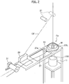
- the capture device 11 is in the second sub-chamber 3c and is so arranged that the leading end Fe of the reinforcement fiber F vertically hung down is drawn by gravity and then naturally falls down onto the capture device 11. More specifically, the leading end Fe of the reinforcement fiber F can reach the capture device 11 generally only by action of gravity, and the capture device 11 captures and keeps the leading end Fe in place.
- any auxiliary guiding device such as a roller or a funnel may be installed there.
- a guide roller 21 may be installed.
- the guide roller 21 is made movable by an actuator 23.
- the guide roller 21 may be retracted so as not to be in contact with the reinforcement fiber F. then the reinforcement fiber F can freely fall down toward the capture device 11.
- the guide roller 21 is advanced as shown by the chained line to get in contact with the processed reinforcement fiber CF, thereby the reinforcement fiber F is kept vertical in the processor 9 although it is obliquely drawn.
- any device for guiding the reinforcement fiber F can be installed therein.
- Such a device may be installed in any of the first sub-chamber 3a, the main chamber 3b and the second sub-chamber 3c.
- An upper face of the capture device 11 may be formed in any arbitrary shape including a flat plane and may nevertheless have a dent 11H. As the weight W settles in the dent 11H, the capture device 11 more firmly captures and keeps it in place. In place of the dent 11H, applicable is a hole, a cylinder, or a through-hole, in which the weight W fits. Further in place of, or in addition to, these elements, the capture device 11 may have any induction means such as a magnet for inducing the leading end Fe or the weight W, or any adhesive or any viscoelastic body.
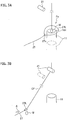
- the vacuum processing device 1 may be comprised of an elevator device 25 for elevating the capture device 11. As shown by the solid line in FIG. 3A , before capturing the leading end Fe, the capture device 11 may be elevated. Further as shown by the chained line therein, before winding the processed reinforced fiber CF around the bobbin 13, the capture device 11 may be moved downward. Such up-and-down movement is advantageous in firmly getting the leading end Fe withdrawn by a resilient cord 27 as described below.
- the vacuum processing device 1 is comprised of the resilient cord 27 in the second sub-chamber 3c, which is for withdrawing the reinforcement fiber F toward the winding bobbin 13.
- the closed loop 27L is placed on a pedestal 10, which is disposed above or around the capture device 11, thereby at this position surrounding the reinforcement fiber F kept in place by the capture device 11.
- the pedestal 10 may be fixed there or movable to this position.
- the pedestal 10 may be a flat plate having a through-hole as shown in the drawing or alternatively formed in a bar-like or belt-like shape.
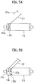
- a proximal end 27p of the resilient cord 27 is, as shown in FIG. 5A , combined with the winding bobbin 13 and is, when the winding bobbin 13 rotates, drawn as indicated by the arrow A in FIG. 3B .
- the resilient cord 27 then gets in contact with the reinforcement fiber F and the leading end Fe slides along the reinforcement fiber F to make the loop 27L shrink so that the loop 27L captures the reinforcement fiber F.
- the resilient cord 27 withdraws the reinforcement fiber F toward the winding bobbin 13.
- the winding bobbin 13 may be comprised of a groove 13G in which the weight W fits and the proximal end 27p may be combined with the groove 13G.
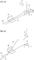
- the resilient cord 27 may, alternatively, as shown in FIG. 4A , form an open loop 27N. Its leading end 27e is fixed to a site other than the resilient cord 27, and the loop 27N is not closed but left opened and as well surrounds the reinforcement fiber F.
- the proximal end 27p is combined with the winding bobbin 13 as with the above example, so that the resilient cord 27 uses rotation thereof to withdraw the reinforcement fiber F toward the winding bobbin 13 as indicated by the arrow A in FIG. 4B .
- the resilient cord 27 then does not rest on a fixed site of the reinforcement fiber F but mutually slides when withdrawing the reinforcement fiber F. As the weight W is unlikely to be wound in this example, the weight W may be left on the capture 11 and may be separated by a cutter 29 as described later.
- the leading end 27e may, nevertheless, be combined with the winding bobbin 13 as shown in FIG. 5B .
- the groove 13G with which the proximal end 27p is combined and a step portion 13L with which the leading end 27e is combined may be formed different in diameter. Traction speeds of the proximal end 27p and the leading end 27e are differentiated as the diameters are different. Then the resilient cord 27 is prevented from resting on a fixed site of the reinforcement fiber F but slides thereon when withdrawing it.
- the groove 13G and the step portion 13L is rotated in a speed different from the main body of the winding bobbin 13.
- Any known mechanism such as a planetary gear is applicable thereto.
- the resilient cord 27 may be connected not to the winding bobbin 13 but to any other induction means that gets in action in synchronism with the winding bobbin 13.
- the winding bobbin 13 along with the capture device 11 is housed in the second sub-chamber 3c. Any actuator such as a motor is connected thereto for its rotation.
- the reinforcement fiber CF processed in the processor 9 is withdrawn by the resilient cord 27, and then wound around the winding bobbin 13.
- the main chamber 3b is gas-tightly separated from the second sub-chamber 3c when the gate 17 is closed, the second sub-chamber 3c is allowed to be exposed to the atmosphere with keeping the main chamber 3b evacuated, thereby allowing carry-in and exchange of the winding bobbin 13.
- the processed reinforcement fiber CF, as being wound around the winding bobbin 13, can be withdrawn.
- the weight W may be, along with the reinforcement fiber CF, wound around the winding bobbin 13 but may be separated therefrom in advance of winding.
- the second sub-chamber 3c may be comprised of a cutter 29 installed therein. Further, it may be comprised of a sensor for determining a time for separating the weight W.
- a revolution counter 31 is used, which is so disposed as to get in contact with the processed reinforcement fiber CF. As travel distance of the reinforcement fiber CF is measured by the revolution counter 31, a time proper for separating the weight W can be determined.
- the process to execute a vacuum processing on a reinforcement fiber by CVD or PVD in accordance with the present embodiment could be executed in a way as described below for example.
- the interior of the chamber 3 is kept in a depressurized state by means of vacuum pumps not shown.
- the gates 15,17 are closed, the first and second sub-chambers 3a,3c are gas-tightly separated from the main chamber 3b.
- the external air is introduced into the first and second sub-chambers 3a,3c so that they are exposed to the atmosphere.
- the interior of the main chamber 3b is even then kept in the depressurized stated.
- the feeding bobbin 5 around which the reinforcement fiber F is wound is introduced into the first sub-chamber 3a exposed to the atmosphere.
- the latter is exchanged for the former.
- the reinforcement fiber F is drawn out of the introduced feeding bobbin 5, made to pass through the tension detector 19 if installed, made to pass through the feeding roller 7 and hung down therefrom. With its leading end Fe, the weight W is combined.
- an empty winding bobbin 13 is introduced into the second sub-chamber 3c exposed to the atmosphere.
- the latter is exchanged for the former.
- first and second sub-chambers 3a,3c After closing the first and second sub-chambers 3a,3c, they are evacuated by means of the pumps not shown. After the degree of vacuum in the interior reaches a desirable level, the gates 15,17 are opened and then the first sub-chamber 3a, the main chamber 3b and the second sub-chamber 3c mutually get in spatial communication. The guide roller 21 then keeps retracting as shown in FIG. 2 .
- the reinforcement fiber F vertically hung down from the feeding roller 7 passes through the processor 9 disposed in the main chamber 3b.
- the reinforcement fiber F after passing the processor 9 further falls down vertically and the leading end thereof reaches the capture device 11.
- the weight W combined with the leading end Fe settles in the capture device 11, thereby keeping the leading end Fe in place.
- the capture device 11 may be elevated to a height comparable to the closed loop 27L or the open loop 27N of the resilient cord 27 on the pedestal 10.
- the capture device 11 is moved down and then the reinforcement fiber F is made surrounded by the loop 27L or the loop 27N as shown in FIG. 3A or FIG. 4A .
- the guide roller 21 is advanced to get in contact with the reinforcement fiber F.
- the winding bobbin 13 or the induction device is put in action to withdraw the resilient cord 27, thereby making the resilient cord 27 in contact with the reinforcement fiber F and making the resilient cord 27 to accompany the reinforcement fiber F toward the winding bobbin 13.
- the cutter 29 may be put in action to separate the weight W. Whether it reaches the winding bobbin 13 or not can be determined by using the revolution counter 31.
- the processor 9 is put in action to execute a processing such as coating on the reinforcement fiber F, and simultaneously the winding bobbin 13 is rotated to wind the processed reinforcement fiber CF around the winding bobbin 13.
- the vacuum processing ends and the bobbin is subject to exchange, it is necessary to expose the first and second sub-chambers to the atmosphere whereas the main chamber can be kept evacuated. Because the main chamber, as being the largest in both volume and internal area among elements of the vacuum processing device, can be kept evacuated, only a short time is required for evacuation after exchange of bobbins to obtain a desired degree of vacuum. Therefore the vacuum processing can be repeated with high productivity.
- the work for combining the fiber with the bobbin can be executed under an evacuated situation in accordance with the present embodiment.
- this work would be readily executed by hands.
- a suction nozzle can be used to keep the fiber in place as the fiber can be sucked along with the air into the nozzle, and then a movable arm can be used for withdrawing the fiber.
- this work can be automated. As this work, however, is executed after the fiber passes the main chamber, the main chamber have to be necessarily exposed to the atmosphere. This, as discussed already, seriously hurts productivity. Under the vacuum, both work by hands and suction by a nozzle are impossible.
- the present embodiment enables such work under the vacuum as automatic processing because the capture device keeps the reinforcement fiber in place and thereafter the resilient cord withdraws the fiber toward the winding bobbin. Necessarily, the main chamber is not necessitated to be exposed to the atmosphere and therefore high productivity is given.
- a vacuum processing device is provided, which enables exchanging bobbins with keeping the most of the device evacuated.
Landscapes
- Chemical & Material Sciences (AREA)
- Engineering & Computer Science (AREA)
- Mechanical Engineering (AREA)
- Materials Engineering (AREA)
- Chemical Kinetics & Catalysis (AREA)
- Metallurgy (AREA)
- Organic Chemistry (AREA)
- General Chemical & Material Sciences (AREA)
- Inorganic Chemistry (AREA)
- General Engineering & Computer Science (AREA)
- Chemical Vapour Deposition (AREA)
- Treatment Of Fiber Materials (AREA)
- Physical Vapour Deposition (AREA)
- Moulding By Coating Moulds (AREA)
Applications Claiming Priority (2)
| Application Number | Priority Date | Filing Date | Title |
|---|---|---|---|
| JP2014081971A JP6282917B2 (ja) | 2014-04-11 | 2014-04-11 | 真空処理装置 |
| PCT/JP2015/061133 WO2015156361A1 (fr) | 2014-04-11 | 2015-04-09 | Dispositif de traitement sous vide |
Publications (3)
| Publication Number | Publication Date |
|---|---|
| EP3130690A1 true EP3130690A1 (fr) | 2017-02-15 |
| EP3130690A4 EP3130690A4 (fr) | 2017-12-27 |
| EP3130690B1 EP3130690B1 (fr) | 2020-06-24 |
Family
ID=54287933
Family Applications (1)
| Application Number | Title | Priority Date | Filing Date |
|---|---|---|---|
| EP15776174.3A Active EP3130690B1 (fr) | 2014-04-11 | 2015-04-09 | Dispositif de traitement sous vide |
Country Status (7)
| Country | Link |
|---|---|
| US (1) | US10443122B2 (fr) |
| EP (1) | EP3130690B1 (fr) |
| JP (1) | JP6282917B2 (fr) |
| CN (1) | CN106164333B (fr) |
| CA (1) | CA2944326C (fr) |
| RU (1) | RU2660457C2 (fr) |
| WO (1) | WO2015156361A1 (fr) |
Cited By (1)
| Publication number | Priority date | Publication date | Assignee | Title |
|---|---|---|---|---|
| EP4431633A1 (fr) * | 2023-01-12 | 2024-09-18 | Honeywell International Inc. | Traitement sous vide continu de câbles de fibres |
Families Citing this family (6)
| Publication number | Priority date | Publication date | Assignee | Title |
|---|---|---|---|---|
| US10099890B2 (en) * | 2015-08-02 | 2018-10-16 | Medicines360 | Devices, systems and methods for knot tying |
| CA3083255A1 (fr) | 2017-11-27 | 2019-05-31 | Ihi Corporation | Fibre de renfort revetue resistant a l'environnement destinee a etre utilisee dans un materiau composite renforce par fibres |
| CN108359962B (zh) * | 2018-04-12 | 2020-08-04 | 泰州润杰物流安全装备科技有限公司 | 化纤织带涂氧化铝层的方法和装置 |
| DE102018215100A1 (de) * | 2018-05-28 | 2019-11-28 | Sms Group Gmbh | Vakuumbeschichtungsanlage, und Verfahren zum Beschichten eines bandförmigen Materials |
| JP7136332B2 (ja) * | 2019-03-28 | 2022-09-13 | 株式会社Ihi | 真空処理装置 |
| JP7136331B2 (ja) * | 2019-03-28 | 2022-09-13 | 株式会社Ihi | 真空処理装置 |
Family Cites Families (15)
| Publication number | Priority date | Publication date | Assignee | Title |
|---|---|---|---|---|
| US4343836A (en) * | 1979-07-26 | 1982-08-10 | United States Of America As Represented By The United States Department Of Energy | One-directional uniformly coated fibers, method of preparation, and uses therefor |
| JPS5984586A (ja) * | 1982-11-08 | 1984-05-16 | Hitachi Ltd | 薄膜太陽電池の連続製造装置 |
| US5405654A (en) * | 1989-07-21 | 1995-04-11 | Minnesota Mining And Manufacturing Company | Self-cleaning chemical vapor deposition apparatus and method |
| JP3122216B2 (ja) * | 1992-03-05 | 2001-01-09 | キヤノン株式会社 | ゲート及び真空処理装置 |
| RU2085628C1 (ru) * | 1992-11-19 | 1997-07-27 | Государственный научно-исследовательский институт конструкционных материалов на основе графита | Установка для модификации поверхности углеродных волокнистых материалов в газовой атмосфере |
| JPH06172033A (ja) * | 1992-12-11 | 1994-06-21 | Nippon Cement Co Ltd | 表面被覆炭素繊維強化複合材料及びその製造方法 |
| JPH07197264A (ja) * | 1993-12-29 | 1995-08-01 | Tonen Corp | 繊維の表面処理方法、強化繊維及び応用 |
| NL1015690C2 (nl) | 2000-07-12 | 2002-01-15 | Otb Group Bv | Sluis voor vacu³mkamer. |
| EP1209252A3 (fr) * | 2000-09-15 | 2002-11-27 | Shipley Co. L.L.C. | Dispositif pour le revêtement en continu |
| JP2003144900A (ja) * | 2001-11-13 | 2003-05-20 | Sumitomo Heavy Ind Ltd | 連続真空処理装置 |
| FR2911524B1 (fr) * | 2007-01-23 | 2009-08-21 | Snecma Sa | Piece tubulaire comportant un insert en matiere composite a matrice metallique. |
| JP5458915B2 (ja) | 2010-01-29 | 2014-04-02 | 宇部興産株式会社 | 複合材料用開繊無機繊維束及びその製造方法、並びに該繊維束で強化されたセラミックス基複合材料 |
| JP5649040B2 (ja) | 2010-06-30 | 2015-01-07 | パナソニックIpマネジメント株式会社 | 炊飯器 |
| JP6003513B2 (ja) * | 2012-10-15 | 2016-10-05 | 株式会社Ihi | 高温処理炉及び強化繊維の継ぎ方法 |
| US20150021869A1 (en) * | 2013-07-22 | 2015-01-22 | Hal Clayton Morgan, Jr. | Knee scooter |
-
2014
- 2014-04-11 JP JP2014081971A patent/JP6282917B2/ja active Active
-
2015
- 2015-04-09 RU RU2016143724A patent/RU2660457C2/ru active
- 2015-04-09 CA CA2944326A patent/CA2944326C/fr active Active
- 2015-04-09 CN CN201580017283.3A patent/CN106164333B/zh active Active
- 2015-04-09 EP EP15776174.3A patent/EP3130690B1/fr active Active
- 2015-04-09 WO PCT/JP2015/061133 patent/WO2015156361A1/fr not_active Ceased
-
2016
- 2016-10-03 US US15/284,155 patent/US10443122B2/en active Active
Cited By (1)
| Publication number | Priority date | Publication date | Assignee | Title |
|---|---|---|---|---|
| EP4431633A1 (fr) * | 2023-01-12 | 2024-09-18 | Honeywell International Inc. | Traitement sous vide continu de câbles de fibres |
Also Published As
| Publication number | Publication date |
|---|---|
| CA2944326C (fr) | 2018-02-20 |
| CN106164333B (zh) | 2018-11-02 |
| CN106164333A (zh) | 2016-11-23 |
| RU2016143724A3 (fr) | 2018-05-11 |
| CA2944326A1 (fr) | 2015-10-15 |
| JP2015203129A (ja) | 2015-11-16 |
| EP3130690B1 (fr) | 2020-06-24 |
| JP6282917B2 (ja) | 2018-02-21 |
| US10443122B2 (en) | 2019-10-15 |
| US20170022606A1 (en) | 2017-01-26 |
| EP3130690A4 (fr) | 2017-12-27 |
| WO2015156361A1 (fr) | 2015-10-15 |
| RU2016143724A (ru) | 2018-05-11 |
| RU2660457C2 (ru) | 2018-07-06 |
Similar Documents
| Publication | Publication Date | Title |
|---|---|---|
| US10443122B2 (en) | Vacuum processing device | |
| KR101494604B1 (ko) | 파이프 이송장치 | |
| CN101235582B (zh) | 用于为缩毡机用针板进行装备的方法和装置 | |
| CN108431906A (zh) | 用于冷却线缆的系统 | |
| CN113286753B (zh) | 处理棒材的设备和方法 | |
| KR102107105B1 (ko) | 증착율 측정센서의 교체 기구가 개선된 증착 장치 및 그것을 이용한 증착율 측정센서의 교체 방법 | |
| US12031211B2 (en) | Vacuum processing device | |
| US12152299B2 (en) | Vacuum processing device | |
| JP2018506969A5 (fr) | ||
| JP2018517638A (ja) | 光ファイバ製造機械、そのタイプの機械において光ファイバを位置決めする方法 | |
| EP3464707B1 (fr) | Poste de qualification et de réparation | |
| CN209777627U (zh) | 一种用于输送筒管纱的输送装置 | |
| CN207435596U (zh) | 一种抽丝装置 | |
| CN106904318B (zh) | 食品容器供给装置 | |
| JP2020061400A (ja) | 基板保持装置 | |
| CN222948711U (zh) | 一种棉纱纺织用定量剪切装置 | |
| ITUB20155052A1 (it) | Apparecchiatura modulare per la determinazione automatica di caratteristiche di campioni tessili allungati del tipo di filati, fili, nastri e simili. | |
| EP3873686A1 (fr) | Procédé et appareil d'alimentation d'éléments allongés | |
| JP2016011479A (ja) | 高アルミナ組成無機繊維、無機繊維集合体及び無機繊維成型体 | |
| CN215677958U (zh) | 一种毛纱收集装置及玻璃纤维无捻粗纱毛纱量检测设备 | |
| CN203174199U (zh) | 一种化学气相沉积升降装置 | |
| ITGE20120062A1 (it) | Sistema di confezionamento di pacchi multistrato su bancali, pallet o simili | |
| CN113699623A (zh) | 一种棉纱生产用梳棉集料装置 | |
| ITRM20080490A1 (it) | Apparecchiatura per raggruppare manufatti. | |
| ITMO950092A1 (it) | Apparecchiatura per la formazione in continuo di file ordinate di oggetti (piastrelle) e per il trasbordo rapido delle stesse |
Legal Events
| Date | Code | Title | Description |
|---|---|---|---|
| STAA | Information on the status of an ep patent application or granted ep patent |
Free format text: STATUS: THE INTERNATIONAL PUBLICATION HAS BEEN MADE |
|
| PUAI | Public reference made under article 153(3) epc to a published international application that has entered the european phase |
Free format text: ORIGINAL CODE: 0009012 |
|
| STAA | Information on the status of an ep patent application or granted ep patent |
Free format text: STATUS: REQUEST FOR EXAMINATION WAS MADE |
|
| 17P | Request for examination filed |
Effective date: 20161111 |
|
| AK | Designated contracting states |
Kind code of ref document: A1 Designated state(s): AL AT BE BG CH CY CZ DE DK EE ES FI FR GB GR HR HU IE IS IT LI LT LU LV MC MK MT NL NO PL PT RO RS SE SI SK SM TR |
|
| AX | Request for extension of the european patent |
Extension state: BA ME |
|
| DAV | Request for validation of the european patent (deleted) | ||
| DAX | Request for extension of the european patent (deleted) | ||
| A4 | Supplementary search report drawn up and despatched |
Effective date: 20171129 |
|
| RIC1 | Information provided on ipc code assigned before grant |
Ipc: C23C 16/54 20060101AFI20171123BHEP Ipc: D06M 10/00 20060101ALI20171123BHEP Ipc: C23C 14/56 20060101ALI20171123BHEP Ipc: B65H 69/04 20060101ALI20171123BHEP Ipc: F27B 9/28 20060101ALI20171123BHEP Ipc: C04B 41/87 20060101ALI20171123BHEP Ipc: B65H 51/28 20060101ALI20171123BHEP Ipc: C04B 35/80 20060101ALI20171123BHEP |
|
| STAA | Information on the status of an ep patent application or granted ep patent |
Free format text: STATUS: EXAMINATION IS IN PROGRESS |
|
| 17Q | First examination report despatched |
Effective date: 20190416 |
|
| GRAP | Despatch of communication of intention to grant a patent |
Free format text: ORIGINAL CODE: EPIDOSNIGR1 |
|
| STAA | Information on the status of an ep patent application or granted ep patent |
Free format text: STATUS: GRANT OF PATENT IS INTENDED |
|
| INTG | Intention to grant announced |
Effective date: 20200131 |
|
| GRAS | Grant fee paid |
Free format text: ORIGINAL CODE: EPIDOSNIGR3 |
|
| GRAA | (expected) grant |
Free format text: ORIGINAL CODE: 0009210 |
|
| STAA | Information on the status of an ep patent application or granted ep patent |
Free format text: STATUS: THE PATENT HAS BEEN GRANTED |
|
| AK | Designated contracting states |
Kind code of ref document: B1 Designated state(s): AL AT BE BG CH CY CZ DE DK EE ES FI FR GB GR HR HU IE IS IT LI LT LU LV MC MK MT NL NO PL PT RO RS SE SI SK SM TR |
|
| REG | Reference to a national code |
Ref country code: GB Ref legal event code: FG4D |
|
| RIN1 | Information on inventor provided before grant (corrected) |
Inventor name: TANAKA, YASUTOMO Inventor name: SODENO, KENICHI Inventor name: NAKADA, YUKIHIRO Inventor name: WATANABE, KENICHIRO Inventor name: KITAGAWA, HIDEKI |
|
| REG | Reference to a national code |
Ref country code: CH Ref legal event code: EP |
|
| REG | Reference to a national code |
Ref country code: AT Ref legal event code: REF Ref document number: 1283987 Country of ref document: AT Kind code of ref document: T Effective date: 20200715 |
|
| REG | Reference to a national code |
Ref country code: DE Ref legal event code: R096 Ref document number: 602015054750 Country of ref document: DE |
|
| REG | Reference to a national code |
Ref country code: IE Ref legal event code: FG4D |
|
| PG25 | Lapsed in a contracting state [announced via postgrant information from national office to epo] |
Ref country code: GR Free format text: LAPSE BECAUSE OF FAILURE TO SUBMIT A TRANSLATION OF THE DESCRIPTION OR TO PAY THE FEE WITHIN THE PRESCRIBED TIME-LIMIT Effective date: 20200925 Ref country code: FI Free format text: LAPSE BECAUSE OF FAILURE TO SUBMIT A TRANSLATION OF THE DESCRIPTION OR TO PAY THE FEE WITHIN THE PRESCRIBED TIME-LIMIT Effective date: 20200624 Ref country code: NO Free format text: LAPSE BECAUSE OF FAILURE TO SUBMIT A TRANSLATION OF THE DESCRIPTION OR TO PAY THE FEE WITHIN THE PRESCRIBED TIME-LIMIT Effective date: 20200924 Ref country code: LT Free format text: LAPSE BECAUSE OF FAILURE TO SUBMIT A TRANSLATION OF THE DESCRIPTION OR TO PAY THE FEE WITHIN THE PRESCRIBED TIME-LIMIT Effective date: 20200624 Ref country code: SE Free format text: LAPSE BECAUSE OF FAILURE TO SUBMIT A TRANSLATION OF THE DESCRIPTION OR TO PAY THE FEE WITHIN THE PRESCRIBED TIME-LIMIT Effective date: 20200624 |
|
| REG | Reference to a national code |
Ref country code: LT Ref legal event code: MG4D |
|
| PG25 | Lapsed in a contracting state [announced via postgrant information from national office to epo] |
Ref country code: RS Free format text: LAPSE BECAUSE OF FAILURE TO SUBMIT A TRANSLATION OF THE DESCRIPTION OR TO PAY THE FEE WITHIN THE PRESCRIBED TIME-LIMIT Effective date: 20200624 Ref country code: LV Free format text: LAPSE BECAUSE OF FAILURE TO SUBMIT A TRANSLATION OF THE DESCRIPTION OR TO PAY THE FEE WITHIN THE PRESCRIBED TIME-LIMIT Effective date: 20200624 Ref country code: HR Free format text: LAPSE BECAUSE OF FAILURE TO SUBMIT A TRANSLATION OF THE DESCRIPTION OR TO PAY THE FEE WITHIN THE PRESCRIBED TIME-LIMIT Effective date: 20200624 Ref country code: BG Free format text: LAPSE BECAUSE OF FAILURE TO SUBMIT A TRANSLATION OF THE DESCRIPTION OR TO PAY THE FEE WITHIN THE PRESCRIBED TIME-LIMIT Effective date: 20200924 |
|
| REG | Reference to a national code |
Ref country code: NL Ref legal event code: MP Effective date: 20200624 |
|
| REG | Reference to a national code |
Ref country code: AT Ref legal event code: MK05 Ref document number: 1283987 Country of ref document: AT Kind code of ref document: T Effective date: 20200624 |
|
| PG25 | Lapsed in a contracting state [announced via postgrant information from national office to epo] |
Ref country code: AL Free format text: LAPSE BECAUSE OF FAILURE TO SUBMIT A TRANSLATION OF THE DESCRIPTION OR TO PAY THE FEE WITHIN THE PRESCRIBED TIME-LIMIT Effective date: 20200624 Ref country code: NL Free format text: LAPSE BECAUSE OF FAILURE TO SUBMIT A TRANSLATION OF THE DESCRIPTION OR TO PAY THE FEE WITHIN THE PRESCRIBED TIME-LIMIT Effective date: 20200624 |
|
| PG25 | Lapsed in a contracting state [announced via postgrant information from national office to epo] |
Ref country code: PT Free format text: LAPSE BECAUSE OF FAILURE TO SUBMIT A TRANSLATION OF THE DESCRIPTION OR TO PAY THE FEE WITHIN THE PRESCRIBED TIME-LIMIT Effective date: 20201026 Ref country code: ES Free format text: LAPSE BECAUSE OF FAILURE TO SUBMIT A TRANSLATION OF THE DESCRIPTION OR TO PAY THE FEE WITHIN THE PRESCRIBED TIME-LIMIT Effective date: 20200624 Ref country code: CZ Free format text: LAPSE BECAUSE OF FAILURE TO SUBMIT A TRANSLATION OF THE DESCRIPTION OR TO PAY THE FEE WITHIN THE PRESCRIBED TIME-LIMIT Effective date: 20200624 Ref country code: RO Free format text: LAPSE BECAUSE OF FAILURE TO SUBMIT A TRANSLATION OF THE DESCRIPTION OR TO PAY THE FEE WITHIN THE PRESCRIBED TIME-LIMIT Effective date: 20200624 Ref country code: EE Free format text: LAPSE BECAUSE OF FAILURE TO SUBMIT A TRANSLATION OF THE DESCRIPTION OR TO PAY THE FEE WITHIN THE PRESCRIBED TIME-LIMIT Effective date: 20200624 Ref country code: SM Free format text: LAPSE BECAUSE OF FAILURE TO SUBMIT A TRANSLATION OF THE DESCRIPTION OR TO PAY THE FEE WITHIN THE PRESCRIBED TIME-LIMIT Effective date: 20200624 Ref country code: AT Free format text: LAPSE BECAUSE OF FAILURE TO SUBMIT A TRANSLATION OF THE DESCRIPTION OR TO PAY THE FEE WITHIN THE PRESCRIBED TIME-LIMIT Effective date: 20200624 |
|
| PG25 | Lapsed in a contracting state [announced via postgrant information from national office to epo] |
Ref country code: PL Free format text: LAPSE BECAUSE OF FAILURE TO SUBMIT A TRANSLATION OF THE DESCRIPTION OR TO PAY THE FEE WITHIN THE PRESCRIBED TIME-LIMIT Effective date: 20200624 Ref country code: SK Free format text: LAPSE BECAUSE OF FAILURE TO SUBMIT A TRANSLATION OF THE DESCRIPTION OR TO PAY THE FEE WITHIN THE PRESCRIBED TIME-LIMIT Effective date: 20200624 Ref country code: IS Free format text: LAPSE BECAUSE OF FAILURE TO SUBMIT A TRANSLATION OF THE DESCRIPTION OR TO PAY THE FEE WITHIN THE PRESCRIBED TIME-LIMIT Effective date: 20201024 |
|
| REG | Reference to a national code |
Ref country code: DE Ref legal event code: R097 Ref document number: 602015054750 Country of ref document: DE |
|
| PG25 | Lapsed in a contracting state [announced via postgrant information from national office to epo] |
Ref country code: DK Free format text: LAPSE BECAUSE OF FAILURE TO SUBMIT A TRANSLATION OF THE DESCRIPTION OR TO PAY THE FEE WITHIN THE PRESCRIBED TIME-LIMIT Effective date: 20200624 |
|
| PLBE | No opposition filed within time limit |
Free format text: ORIGINAL CODE: 0009261 |
|
| STAA | Information on the status of an ep patent application or granted ep patent |
Free format text: STATUS: NO OPPOSITION FILED WITHIN TIME LIMIT |
|
| 26N | No opposition filed |
Effective date: 20210325 |
|
| PG25 | Lapsed in a contracting state [announced via postgrant information from national office to epo] |
Ref country code: SI Free format text: LAPSE BECAUSE OF FAILURE TO SUBMIT A TRANSLATION OF THE DESCRIPTION OR TO PAY THE FEE WITHIN THE PRESCRIBED TIME-LIMIT Effective date: 20200624 |
|
| PG25 | Lapsed in a contracting state [announced via postgrant information from national office to epo] |
Ref country code: MC Free format text: LAPSE BECAUSE OF FAILURE TO SUBMIT A TRANSLATION OF THE DESCRIPTION OR TO PAY THE FEE WITHIN THE PRESCRIBED TIME-LIMIT Effective date: 20200624 |
|
| PG25 | Lapsed in a contracting state [announced via postgrant information from national office to epo] |
Ref country code: LU Free format text: LAPSE BECAUSE OF NON-PAYMENT OF DUE FEES Effective date: 20210409 |
|
| REG | Reference to a national code |
Ref country code: BE Ref legal event code: MM Effective date: 20210430 |
|
| PG25 | Lapsed in a contracting state [announced via postgrant information from national office to epo] |
Ref country code: CH Free format text: LAPSE BECAUSE OF NON-PAYMENT OF DUE FEES Effective date: 20210430 Ref country code: LI Free format text: LAPSE BECAUSE OF NON-PAYMENT OF DUE FEES Effective date: 20210430 |
|
| PG25 | Lapsed in a contracting state [announced via postgrant information from national office to epo] |
Ref country code: IE Free format text: LAPSE BECAUSE OF NON-PAYMENT OF DUE FEES Effective date: 20210409 |
|
| PG25 | Lapsed in a contracting state [announced via postgrant information from national office to epo] |
Ref country code: IS Free format text: LAPSE BECAUSE OF FAILURE TO SUBMIT A TRANSLATION OF THE DESCRIPTION OR TO PAY THE FEE WITHIN THE PRESCRIBED TIME-LIMIT Effective date: 20201024 |
|
| PG25 | Lapsed in a contracting state [announced via postgrant information from national office to epo] |
Ref country code: BE Free format text: LAPSE BECAUSE OF NON-PAYMENT OF DUE FEES Effective date: 20210430 |
|
| PG25 | Lapsed in a contracting state [announced via postgrant information from national office to epo] |
Ref country code: HU Free format text: LAPSE BECAUSE OF FAILURE TO SUBMIT A TRANSLATION OF THE DESCRIPTION OR TO PAY THE FEE WITHIN THE PRESCRIBED TIME-LIMIT; INVALID AB INITIO Effective date: 20150409 |
|
| PG25 | Lapsed in a contracting state [announced via postgrant information from national office to epo] |
Ref country code: CY Free format text: LAPSE BECAUSE OF FAILURE TO SUBMIT A TRANSLATION OF THE DESCRIPTION OR TO PAY THE FEE WITHIN THE PRESCRIBED TIME-LIMIT Effective date: 20200624 |
|
| PG25 | Lapsed in a contracting state [announced via postgrant information from national office to epo] |
Ref country code: MK Free format text: LAPSE BECAUSE OF FAILURE TO SUBMIT A TRANSLATION OF THE DESCRIPTION OR TO PAY THE FEE WITHIN THE PRESCRIBED TIME-LIMIT Effective date: 20200624 |
|
| PG25 | Lapsed in a contracting state [announced via postgrant information from national office to epo] |
Ref country code: MT Free format text: LAPSE BECAUSE OF FAILURE TO SUBMIT A TRANSLATION OF THE DESCRIPTION OR TO PAY THE FEE WITHIN THE PRESCRIBED TIME-LIMIT Effective date: 20200624 |
|
| PGFP | Annual fee paid to national office [announced via postgrant information from national office to epo] |
Ref country code: DE Payment date: 20250305 Year of fee payment: 11 |
|
| PG25 | Lapsed in a contracting state [announced via postgrant information from national office to epo] |
Ref country code: TR Free format text: LAPSE BECAUSE OF FAILURE TO SUBMIT A TRANSLATION OF THE DESCRIPTION OR TO PAY THE FEE WITHIN THE PRESCRIBED TIME-LIMIT Effective date: 20200624 |
|
| PGFP | Annual fee paid to national office [announced via postgrant information from national office to epo] |
Ref country code: GB Payment date: 20260313 Year of fee payment: 12 |
|
| PGFP | Annual fee paid to national office [announced via postgrant information from national office to epo] |
Ref country code: IT Payment date: 20260320 Year of fee payment: 12 |
|
| PGFP | Annual fee paid to national office [announced via postgrant information from national office to epo] |
Ref country code: FR Payment date: 20260309 Year of fee payment: 12 |