EP3132713B1 - Dispositif destine a deplacer un element de meuble mobile - Google Patents
Dispositif destine a deplacer un element de meuble mobile Download PDFInfo
- Publication number
- EP3132713B1 EP3132713B1 EP16181470.2A EP16181470A EP3132713B1 EP 3132713 B1 EP3132713 B1 EP 3132713B1 EP 16181470 A EP16181470 A EP 16181470A EP 3132713 B1 EP3132713 B1 EP 3132713B1
- Authority
- EP
- European Patent Office
- Prior art keywords
- furniture
- component
- section
- piece
- drawer
- Prior art date
- Legal status (The legal status is an assumption and is not a legal conclusion. Google has not performed a legal analysis and makes no representation as to the accuracy of the status listed.)
- Active
Links
Images




Classifications
-
- E—FIXED CONSTRUCTIONS
- E05—LOCKS; KEYS; WINDOW OR DOOR FITTINGS; SAFES
- E05F—DEVICES FOR MOVING WINGS INTO OPEN OR CLOSED POSITION; CHECKS FOR WINGS; WING FITTINGS NOT OTHERWISE PROVIDED FOR, CONCERNED WITH THE FUNCTIONING OF THE WING
- E05F1/00—Closers or openers for wings, not otherwise provided for in this subclass
- E05F1/08—Closers or openers for wings, not otherwise provided for in this subclass spring-actuated, e.g. for horizontally sliding wings
- E05F1/16—Closers or openers for wings, not otherwise provided for in this subclass spring-actuated, e.g. for horizontally sliding wings for sliding wings
-
- A—HUMAN NECESSITIES
- A47—FURNITURE; DOMESTIC ARTICLES OR APPLIANCES; COFFEE MILLS; SPICE MILLS; SUCTION CLEANERS IN GENERAL
- A47B—TABLES; DESKS; OFFICE FURNITURE; CABINETS; DRAWERS; GENERAL DETAILS OF FURNITURE
- A47B88/00—Drawers for tables, cabinets or like furniture; Guides for drawers
- A47B88/40—Sliding drawers; Slides or guides therefor
- A47B88/453—Actuated drawers
- A47B88/46—Actuated drawers operated by mechanically-stored energy, e.g. by springs
- A47B88/463—Actuated drawers operated by mechanically-stored energy, e.g. by springs self-opening
-
- A—HUMAN NECESSITIES
- A47—FURNITURE; DOMESTIC ARTICLES OR APPLIANCES; COFFEE MILLS; SPICE MILLS; SUCTION CLEANERS IN GENERAL
- A47B—TABLES; DESKS; OFFICE FURNITURE; CABINETS; DRAWERS; GENERAL DETAILS OF FURNITURE
- A47B2210/00—General construction of drawers, guides and guide devices
- A47B2210/0002—Guide construction for drawers
- A47B2210/0051—Guide position
- A47B2210/0056—Guide located at the bottom of the drawer
-
- E—FIXED CONSTRUCTIONS
- E05—LOCKS; KEYS; WINDOW OR DOOR FITTINGS; SAFES
- E05F—DEVICES FOR MOVING WINGS INTO OPEN OR CLOSED POSITION; CHECKS FOR WINGS; WING FITTINGS NOT OTHERWISE PROVIDED FOR, CONCERNED WITH THE FUNCTIONING OF THE WING
- E05F5/00—Braking devices, e.g. checks; Stops; Buffers
- E05F5/003—Braking devices, e.g. checks; Stops; Buffers for sliding wings
-
- E—FIXED CONSTRUCTIONS
- E05—LOCKS; KEYS; WINDOW OR DOOR FITTINGS; SAFES
- E05Y—INDEXING SCHEME ASSOCIATED WITH SUBCLASSES E05D AND E05F, RELATING TO CONSTRUCTION ELEMENTS, ELECTRIC CONTROL, POWER SUPPLY, POWER SIGNAL OR TRANSMISSION, USER INTERFACES, MOUNTING OR COUPLING, DETAILS, ACCESSORIES, AUXILIARY OPERATIONS NOT OTHERWISE PROVIDED FOR, APPLICATION THEREOF
- E05Y2201/00—Constructional elements; Accessories therefor
- E05Y2201/40—Motors; Magnets; Springs; Weights; Accessories therefor
- E05Y2201/404—Function thereof
- E05Y2201/422—Function thereof for opening
- E05Y2201/426—Function thereof for opening for the initial opening movement
-
- E—FIXED CONSTRUCTIONS
- E05—LOCKS; KEYS; WINDOW OR DOOR FITTINGS; SAFES
- E05Y—INDEXING SCHEME ASSOCIATED WITH SUBCLASSES E05D AND E05F, RELATING TO CONSTRUCTION ELEMENTS, ELECTRIC CONTROL, POWER SUPPLY, POWER SIGNAL OR TRANSMISSION, USER INTERFACES, MOUNTING OR COUPLING, DETAILS, ACCESSORIES, AUXILIARY OPERATIONS NOT OTHERWISE PROVIDED FOR, APPLICATION THEREOF
- E05Y2201/00—Constructional elements; Accessories therefor
- E05Y2201/60—Suspension or transmission members; Accessories therefor
- E05Y2201/622—Suspension or transmission members elements
- E05Y2201/624—Arms
-
- E—FIXED CONSTRUCTIONS
- E05—LOCKS; KEYS; WINDOW OR DOOR FITTINGS; SAFES
- E05Y—INDEXING SCHEME ASSOCIATED WITH SUBCLASSES E05D AND E05F, RELATING TO CONSTRUCTION ELEMENTS, ELECTRIC CONTROL, POWER SUPPLY, POWER SIGNAL OR TRANSMISSION, USER INTERFACES, MOUNTING OR COUPLING, DETAILS, ACCESSORIES, AUXILIARY OPERATIONS NOT OTHERWISE PROVIDED FOR, APPLICATION THEREOF
- E05Y2600/00—Mounting or coupling arrangements for elements provided for in this subclass
- E05Y2600/10—Adjustable
- E05Y2600/12—Adjustable by manual operation
-
- E—FIXED CONSTRUCTIONS
- E05—LOCKS; KEYS; WINDOW OR DOOR FITTINGS; SAFES
- E05Y—INDEXING SCHEME ASSOCIATED WITH SUBCLASSES E05D AND E05F, RELATING TO CONSTRUCTION ELEMENTS, ELECTRIC CONTROL, POWER SUPPLY, POWER SIGNAL OR TRANSMISSION, USER INTERFACES, MOUNTING OR COUPLING, DETAILS, ACCESSORIES, AUXILIARY OPERATIONS NOT OTHERWISE PROVIDED FOR, APPLICATION THEREOF
- E05Y2900/00—Application of doors, windows, wings or fittings thereof
- E05Y2900/20—Application of doors, windows, wings or fittings thereof for furniture, e.g. cabinets
Definitions
- Devices for influencing the movement of the furniture part are used for furniture parts such as drawers, furniture doors or furniture flaps, which are movably accommodated on a furniture body of a piece of furniture via guide means.
- Such devices are formed, for example, by a unit that can be attached to the furniture part, the furniture body or the guide means at a suitable point.
- the guiding means comprise a sliding guide such as a full or partial extension or a pivoting guide such as a furniture hinge.
- devices for moving the furniture part are known, for example, which can optionally be provided to provide an additional function, in particular to make it easier for a user to open the furniture part.
- the additional function can be matched in particular to the type and size of the furniture part.
- the device for influencing the movement of the furniture part relates to z. B. Systems for providing a power-assisted opening function for the furniture part. the kind the connection of the device must be taken into account in each case.
- the DE 10 2010 036 903 A1 relates to an ejection device and extraction system.
- the AT 508 139 A4 proposes a furniture drive with touch-latch device.
- the DE 10 2010 031 940 A1 and the WO 2007/087656 A1 are also part of the state of the art. Object and advantages of the invention
- the object of the present invention is to advantageously and flexibly provide an additional function for a furniture part movement or a corresponding piece of furniture by means of a sliding guide, such as a full or partial extension or a pivoting guide. This object is solved by the independent claim.
- the invention is based on a device for moving a movable furniture part in an opening direction of the furniture part in relation to a furniture body of a piece of furniture, the movable furniture part being able to be brought into the opening direction and into a closing direction opposite to the opening direction via guide means, the device comprising a base component , on which an energy storage device is present, so that the movable furniture part can be brought in the opening direction of the movable furniture part under the action of the energy storage device with the mounted device.
- the cover component can be connected to the base component as a separate element.
- the cover component is connected to the base component in a detachable or non-detachable manner, in particular attached in a non-detachable manner to the base component.
- Each variant of the cover component matches the base component, so that the base component and the cover component selected for it are advantageously assembled in the same way.
- the individual connection sections on the respective cover component differ in the individual variants of the cover components. The differences are preferably only present in the connecting means on the cover component.
- the basic functions of the device are implemented on the base component.
- the cover component covers the base component at least on one side, which protects the device with the cover component against dirt and/or damage.
- cover z. B a one-sided flat and at least partially edge-side cover in particular an interior of the device.
- the other flat side of the device is connected to a wall of the base component or a flat side of the base component to the outside.
- sections of the cover component and/or sections of the base component can form the outside of the device, also possibly overlapping.
- these sections are formed at right angles to a main surface side of the base component or the cover component.
- the cover component is formed in particular from a flat sheet metal component by recesses and bends.
- the cover member is made of a plastic material.
- the device is preferably designed as an ejector unit with an energy store that can be loaded during a closing movement of the furniture part.
- the loaded or tensioned energy store is released from a locked position with a triggering process, so that under the action of the force provided by the energy store, the furniture part is moved slightly out of the closed arrangement on the furniture body in the opening direction.
- a release unit with a touch-latch function, an ejection arrangement, a locking mechanism for the tensioned energy store and a loading mechanism for the energy store are preferably present on the device or the base component.
- the covering component has a flat section which extends over a substantial extension of the covering component.
- the flat section extends over a surface which is designed in particular to be flat.
- the flat section forms an outer side of the device, which is opposite to an outer side formed by the base component.
- the cover component is in particular formed in one piece from a material, in particular formed from sheet metal.
- the cover component is comparatively thin, preferably with a constant wall thickness, for example one to two millimeters.
- cutouts, openings, slots, webs and / or bends are present at predetermined locations.
- the cover component has a contact side which is designed for surface contact with an attachment surface of the piece of furniture when the device is mounted on the piece of furniture.
- the mounting surface of the furniture is flat and level.
- the contact side is preferably associated with the surface section of the cover component.
- the device composed of the base component and the cover component can be advantageously arranged on the piece of furniture or on a planar opposite side on the piece of furniture or the piece of furniture.
- the device can be mounted with the abutting side against a flat, flat underside of a drawer bottom.
- the cover component is designed to at least almost completely cover a main side of the base component. An open side or the interior of the base component is thus closed off or protected from the outside.
- the cover component has an edge section which adjoins a flat section of the cover component via a bend.
- the bend on the cover component is present at right angles to the adjacent surface section.
- several differently designed edge sections, which adjoin the surface section are possible.
- Edge sections bent over twice or more, in particular edge sections bent over at right angles, are also conceivable. All bends preferably protrude in the same direction on the contact side, so that the contact side of the cover component is formed without elevations or overhangs.
- the base component or its edge section is matched to the edge section of the cover component in such a way that when the device is assembled, the edge sections complement one another in such a way that the device has a predetermined edge profile, in particular predominantly or completely accommodated within the edge profile of the base component or closed off to the outside is.
- the edge section of the cover component and/or the base component has an edge profile that can be formed in different ways, e.g. B. with or without bending, straight or contoured, convex or concave and the like.
- a narrow side of the base component is covered by a bent edge section of the cover component. In this way, narrow sides of the base component covered by the cover component can be protected against dirt or moisture, for example over a height dimension of the base component.
- the cover component has an edge section with a contour that protrudes outwards relative to adjacent edge sections.
- the connecting means preferably comprise the edge section with the protruding contour.
- the protruding edge section serves to connect the device to mating sections, in particular of guide means.
- the edge sections in question are configured in a way that matches the existing mating sections.
- the shape or contour of the protruding edge section is, for example, tabs, strips and/or tongue-like.
- the edge section with the outwardly protruding contour preferably has outer sides aligned at an angle to one another. In the connection state, the edge portions are with the outwardly projecting contour clamped, latched and/or clipped to the associated mating section on the guide means and/or the piece of furniture.
- the connecting means preferably have claw or hook means for clawing or hooking into a flexible material such as a wooden material of the piece of furniture or the body of the piece of furniture.
- An advantageous modification of the invention is characterized in that the connecting means on the cover component are designed in such a way that the device can be connected to a counter-section on the piece of furniture and/or the guide means without tools. This is advantageous for assembling the device.
- An advantageous embodiment of the invention is formed in that the cover component and the base component are matched to one another in such a way that when the cover component and the base component are in the connected state, a section of the base component protrudes outwards on a narrow side of the device.
- the base component and the cover component are formed with a correlating recess at a common edge portion.
- An operating section of an adjustment arrangement of the device can preferably protrude from the narrow side of the device in the region of the gap formed. The operating section can thus be reached by a person from the outside in order to act manually on the device. In this way, for example, a prestressing of the force accumulator can be set in a fixed manner, which takes place as a function of the mass of the furniture part to be moved.
- connection means are designed for a detachable connection with the guide means of the movable furniture part.
- the means of connection are preferably designed in such a way that a high supporting effect of the device on the guide means is possible.
- the cover component is designed for attachment of the device to an underside of a drawer.
- the device is preferably attached to a side wall of the drawer, for example to a decoration on a hollow chamber frame of the drawer.
- the cover component for connecting the device is designed in the area of a recessed area on the piece of furniture. This enables a particularly space-saving attachment to a piece of furniture or the body of the furniture.
- the cover component In the installed state, the cover component preferably rests with an outside on the bottom of the deepened recess. At the edge of the recess, a corresponding part with a shoulder of the cover component preferably extends out of the depression for attaching the device to the guide means, such as a fixed rail of the guide means, and/or to parts of the furniture part, for example on a side wall of the drawer.
- a wall thickness of the furniture part is greater than a height of the device, so that a residual thickness of the wall remains and forms a bottom of the depression.
- the recessed area is preferably adapted to the height of the device, so that the device can be inserted or lowered in particular completely or flush with the recessed area, for example on the underside of a drawer bottom.
- the device can be accommodated in the recess with a slight overhang to the furniture part wall.
- the indentation is, for example, in the form of a strip and a groove or channel or, in particular, matched to the size and/or shape of the device.
- the recess is preferably open to a rear edge of the drawer base over the width of the recess, but closed to a lateral longitudinal edge of the drawer base.
- the invention also extends to a piece of furniture with a furniture body and a movable furniture part, which can be brought relative to the furniture body via guide means in an opening direction of the furniture part and in a closing direction opposite the opening direction, wherein a device according to one of the above-described configurations is provided.
- the piece of furniture is designed with a guide or with guide means according to a full extension or partial extension, with automatic retraction for drawing the furniture part into a fully closed position being possible with power assistance in the full extension or partial extension.
- a synchronization of the so-called touch-latch functionality is also advantageously provided for two lateral guide units.
- the furniture part is e.g. a drawer, which is slidably accommodated on the opposite body walls of the furniture body via two full pull-out extensions on the side.
- the part of the indentation which is not occupied by the device is preferably covered by a corresponding covering element at the level of the underside of the drawer bottom.
- an extension on the cover member can cover the remainder of the recess.
- a piece of furniture 50 according to the invention with a box-shaped furniture body 51 and a drawer 53 that is movably guided via guide means 52 is figure 1 shown.
- the drawer 53 comprises a drawer bottom 54, a drawer front 55, two opposite side walls 56 and a drawer rear wall 57.
- two guide means 52 acting in the same way are in each case between each side wall 56 of the drawer 53 and an associated body side wall 59 is present.
- a device 58 according to the invention (shown in phantom) for moving or ejecting the furniture part designed as a drawer 53 in the opening direction M1 is arranged on the underside of the drawer bottom 54 .
- figure 2 shows the exploded view of the device 58, which is designed as an ejector unit 1 for the drawer 53.
- the ejector unit 1 is used for power-assisted ejection of the drawer 53 over a first section of the opening movement of the drawer 53 from a closed position relative to the furniture body 51 in the opening direction M1 of the drawer 53.
- the drawer 53 is slidably mounted on the furniture body 51 in the direction M1 and M2 via the guide means 52, for example two identical partial or full extensions.
- the ejector unit 1 can alternatively be arranged on the furniture body 51 or on the guide means 52 of the piece of furniture 50 .
- the ejector unit 1 comprises, among other things, a base plate 2, an energy store 3, a coupling device 4, an ejector 5, a trigger element designed as a trigger 6 and a locking element 7.
- a housing of the ejector unit 1 comprises the base plate 2 and a cover member 9, which consists of figure 9 is evident.
- the ejector unit 1 can be arranged on the underside of the drawer bottom 54 and/or on the guide means 52 via the housing or via the cover component 9 and/or the base plate 2 .
- Holding sections, guide contours, stop elements and/or receiving sections for connecting the individual components of the ejector unit 1 are formed on the base plate 2 .
- the Base plate 2 is designed essentially as a rectangular, elongated or strip-shaped component with a comparatively small height h of approximately 5 to 15 millimeters, for example. Furthermore, the base plate 2 has a width b of approximately 4 to 10 centimeters and a length g.
- the force accumulator 3 comprises two parallel spiral springs 10, 11 of the same type, which form a spring assembly.
- the coil springs 10, 11 are arranged on an adjustable fixed bearing 13 at a first end 12 of the force accumulator 3.
- the fixed bearing 13 comprises a movable bearing part 14, on which the coil springs 10, 11 are detachably but firmly accommodated, and an adjusting part 15 with an operating section 16, via which a user can adjust the position of the end 12 of the energy accumulator 3 from the outside in a variable position-fixed manner.
- a force effect of the energy store 3 on the drawer 53 when the drawer 53 is opened can advantageously be preset.
- the associated ends of the spiral springs 10, 11 are attached to a carriage-like moving element 18.
- the carriage-like movement element 18 is linearly guided via an associated guide contour 19 on the base plate 2 in a direction of movement P1 and an opposite direction of movement P2.
- the directions of movement P1 and P2 of the movement element 18 (see figures 2 , 3 ) run parallel to the opening direction M1 of the drawer 53 and a closing direction M2 opposite thereto.
- the opening direction of the drawer 53 corresponds to the direction P1 and the closing direction of the drawer 53 to the direction P2.
- the Figures 3 , 7 , 8th show the ejector unit 1 in a tensioned state of the energy accumulator 3, in which the spiral springs 10, 11 are stretched or tensioned, in this case the movement element 18 is offset in the direction P1 compared to a position on the base plate 2 that is retracted in the direction P2 and in a Clamping position held.
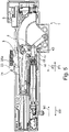
- the figures 5 , 6 show the ejector unit 1 in a discharged basic state of the energy accumulator 3, in which the spiral springs 10, 11 continue to be tensioned, but to a lesser extent, and have a length L1.
- the spiral springs 10, 11 In the clamped state of the force accumulator 3, the spiral springs 10, 11 have a length L2 which is greater than L1.
- a holding element 32 with the stop element 26 is present on the movement element 18 .
- the force accumulator 3 or the movement element 18 is operatively connected to the ejector 5, preferably only when the drawer 53 is closing - and moveable.
- a linear guide 20 is formed on the base plate 2, which z. B. on one side of the ejector 5 is matched.
- An opening process of the drawer 53 brought about by the ejector unit 1 takes place exclusively via a direct operative connection of the energy accumulator 3 via the movement element 18 moving in direction P2 to the ejector 5 .
- a stop element 26 is formed on the movement element 18, which is advantageously designed to be elastic and thus prevents or at least dampens a noise that is bothersome to a user when the movement element 18 hits the ejector 5 during the opening process of the drawer 53 ( figure 3 , 4 , 5 ).
- a front gap adjustment arrangement 8, which is formed on the ejector 5, comprises a housing 45 and an adjusting screw 22 with a contact section 21.
- the adjusting screw 22 has an external thread which cooperates with an internal thread on the housing 45.
- the adjusting screw 22 is in particular designed to be self-locking relative to the housing 45 .
- the contact section 21 of the adjusting screw 22 is in the clamped or loaded state of the force accumulator 3 on a driver 23, which forms a stop for the contact section 21 in corresponding operating states.
- Drivers 23, indicated only by dashed lines, can be present, for example, on a fixed rail of the guide means 52 or can be attached to the furniture body 51 if the ejector unit 1 is arranged on the drawer 53.
- the ejector unit 1 is arranged on the furniture body 51 or on a part of the guide means 52 of the furniture 50 which is fixed in position, then the driver 23 can be present on the drawer 53 and can therefore be movable relative to the furniture body 51 .
- the tensioned or loaded energy accumulator 3 pulls the movement element 18 in the direction P2, which presses or pushes the ejector 5 in the direction P2 relative to the base plate 2 via the stop element 26.
- a latch component 24 pivotably mounted on the ejector 5 of the ejector unit 1 is moved from a pivoted-in position completely countersunk in relation to an outer edge of the base plate 2 figure 4 brought into a swing-out position with a lug partially projecting over the outer edge of the base plate 2 ( figure 5 ), which is realized via a loop-shaped, closed guide track 25 in the base plate 2 and a guide pin 24a engaging therein on the pawl component 24.
- FIGS Figures 3 to 8 To show the pawl component 24, its outline, which is covered by other components, in particular by the ejector 5, is shown in FIGS Figures 3 to 8 indicated by dashed lines.
- the energy accumulator 3 In the basic state shown, the energy accumulator 3 is in an end position of the unloading state, with the energy accumulator 3 not being able to move the ejector 5 any further in the direction of P2.
- the ejector 5 is then moved in the direction P2 relative to the base plate 2 due to the kinetic energy of the drawer 53, which is caused by the previous ejection movement, and/or by a manual further movement of the drawer 53 in the opening direction M1 by a user.
- This is possible because the pawl component 24 pivoted out above the ejector 5 abuts the driver 23, whereby the ejector 5 reaches its end position, which is displaced as far as possible in the direction P2 on the base plate 2, in the further course of the drawer movement.
- the pawl component 24 is fully pivoted again upon reaching the end position on the ejector 5, which is due to the interaction of the guideway 25 with the engaging therein Guide pin 24a on the pawl component 24 is specified.
- the ejector unit 1 separates from the driver 23 and the contact between the driver 23 and the contact section 21 of the adjusting screw 22 is eliminated ( figure 6 ).
- the ejector 5 is pushed by spring elements 33 on the base plate 2, for example by a few millimeters in direction P1.
- the spring elements 33 have a comparatively small force.
- Bearing pin 31 is arranged at a first end of clamping lever 30 and can move freely along a linear guideway 27, for example, and/or a linear guide 63 formed on ejector 5, in particular during an opening process of drawer 53, until the pawl component 24 holds the bearing journal 31 and/or the tensioning lever 30 in direct, play-free contact with the ejector 5.
- the waiting position of the ejector 5, which figure 6 shown is also a starting position of the ejector 5 for a loading process of the energy store 3 via the coupling device 4.
- the coupling device 4 comprises a guide lever 34 and a connecting element 35.
- the clamping lever 30 is articulated at a second end via a bearing pin 36 on the guide lever 34.
- the connecting element 35 is at a second end via a bearing pin 36 spaced from the bearing pin 37 also on the guide lever 34 and articulated at its first end via a further bearing pin 38 on the moving element 18 .
- the guide lever 34 can be moved, in particular pivoted, on the base plate 2 via a bearing pin 39 .
- the bearing journal 39 is preferably accommodated both on the base plate 2 and on the cover component 9 .
- the guide lever 34 of the coupling device 4 comprises a lever attachment 40 at a second end.
- a locking element 41 and a stop element 42 are formed on the lever attachment 40 .
- the end position of the discharge state of the force accumulator 3 ( figure 5 ) is specified by a stop of the stop element 42 of the guide lever 34 on a wall section 47 on a web-like wall 48 of the base plate 2 .
- the wall section 47 is formed, for example, from an annular section of a damping element. If the stop element 42 of the guide lever 34 is in contact with the wall section 47 after the energy accumulator 3 has been discharged, a tensile force in direction P2 is transmitted from the moving element 18 via the connecting element 35 to the guide lever 34 due to the remaining pretension of the spiral springs 10, 11.
- stop element 42 and/or the wall section 47 can be designed to be elastic or dampening, with the result that impact noise is reduced or prevented.
- the guide lever 34 can transmit a force with a translation from the clamping lever 30 to the connecting element 35 when the energy store 3 is being clamped.
- the transmission ratio is formed on the one hand by the ratio of the distance between the bearing pins 39 and 36 and the distance between the bearing pins 39 and 37 on the guide lever 34, and on the other hand by the combined circular and linear movement of the clamping lever 30 and/or the connecting element 35 to one another during the loading process of the power store 4.
- the elements of the coupling device 4 can move as follows:
- the bearing pin 31 and thus the first end of the clamping lever 30 can only move parallel to a direction of movement of the ejector 5 , in particular parallel to a direction of movement of the movable furniture part 53 , due to its mounting in the guideway 27 .
- the bearing pin 38 and thus the first end of the connecting element 35 can only move parallel to a direction of movement of the movement element 18 or of the ejector 5, in particular parallel to the direction of movement of the movable furniture part 53 .
- the bearing pin 36 and thus the second end of the clamping lever 30 can only move in a circular path around a center of rotation of the bearing pin 39 of the guide lever 34 due to its mounting at the second end of the guide lever 34 .
- the bearing pin 37 of the connecting element 35 and thus the second end of the connecting element 35 can only move in a circular path around a center of rotation of the bearing pin 39 of the guide lever 34 due to its bearing in a central region of the guide lever 34 .
- the coupling device 4 can transmit a force for tensioning the energy store 3 from the ejector 5 via the tensioning lever 30 and the guide lever 34 to the connecting element 35 and thus to the energy store 3 in a translated manner; in particular, the coupling device 4 reduces the force exerted by the ejector 5 on the energy storage device 3. This means that when loading the energy storage device 3, a user has to apply less force to the ejector 5 than he would have to apply if he wanted to load the energy storage device 3 without a gear reduction or directly end 17 of the energy storage device 3 in would pull toward P1.
- the tensioning of the energy accumulator 3 takes place with a movement of the drawer 53 during the closing or on a section of the closing movement of the drawer 53 figure 6 .
- the ejector unit 1 moves towards the driver 23 in the direction M2. With the striking of the contact portion 21 of the screw 22 of the ejector 5 on Driver 23 begins the loading process of the energy accumulator 3. For example, due to the inertia of the drawer 53 relative to the base plate 2, the ejector 5 is moved in the direction P1 by hitting the driver 23.
- the movement element 18 of the energy store 3 is also displaced in the direction P1 relative to the base plate 2 and the second end 17 of the spiral springs 10, 11 is displaced in the direction P1 and thus the spiral springs 10 , 11 elongated.
- the ejector 5 At the end of the clamping process of the energy store 3, the ejector 5 is in a loading end position, this is in figure 7 shown. In the clamped state of the energy store 3, the ejector unit 1 is in a locked state.
- the locking element 41 of the coupling device 4 and the locking member 7, which is designed as a flap, determine a locking state, with an unloading movement of the coupling device 4 being blocked by the locking member 7.
- the tensioning of the energy accumulator 3 is fully completed before, for example, an automatic retraction mechanism for force-assisted retraction of the drawer 53 into the fully closed closed position on the furniture body 51 becomes effective.
- the automatic feed is not part of the ejector unit 1 and is integrated, for example, in the guide means 52 or the partial or full extensions.
- the ejector 5 is decoupled from the coupling device 4 and can be moved in the direction P1, in particular by an automatic retraction mechanism, until the drawer 53 is completely closed on the furniture body 51 and the ejector 5 on the trigger 6 is in the basic position according to FIG figure 3 pending.
- the ejector unit 1 In order to eject the drawer 53 with the ejector unit 1 from the fully pushed in or closed position on the furniture carcass 51, a user must exert pressure on the drawer from the outside in the direction M2.
- the ejector unit 1 has a so-called touch-latch functionality, which has a locked state that can be unlocked by moving the inserted drawer 53, which is closed on the furniture body 51, in the closing direction M2.
- This closing movement or the inward pressing of the drawer 53 in direction M2 takes place until a stop position is reached corresponding to a front gap which, when the drawer 53 is closed, is created in particular by a distance between an inside of the drawer front 55 and a front end face or the side walls 56 of the furniture carcass 51 is specified.
- the front gap is usually a few millimeters, for example about 1 to 10 millimeters.
- the unlocking of the ejector unit 1 is coordinated such that a closing movement of the drawer 53 in direction M2 of a few millimeters or at most by the amount of the front gap is sufficient to unlock and thus force-assisted ejection of the drawer 53 safely to pretend
- the ejector unit 1 with the drawer 53 is moved in the direction M2. Since the adjusting screw 22 is present on the driver 23, the ejector 5 is moved relative to the base plate 2 in the direction P1, whereby a contact section 44 on the ejector 5 presses against the trigger 6 and pushes it accordingly in the direction P1.
- the trigger 6 is present on the base plate 2 so that it can be displaced linearly to a limited extent in the direction P1 and P2, usually by a few millimeters or less than the dimension of the front gap.
- the trigger 6 is preferably coupled directly to the locking element 7, which is configured as a flap 43, in such a way that the linear triggering movement of the trigger 6 in direction P1 causes the flap 43 to rotate about a pivot axis D.
- the rotary movement releases the flap 43 from a locking position into which the flap 43 is urged by a spring element designed as a leaf spring 49 .
- the flap 43 In the locked state of the ejector unit 1, the flap 43, which is in the locking position, blocks the guide lever 34 or the lever attachment 40 in such a way that the energy store 3 remains in its charged state.
- the locking element 41 which is pretensioned by a torsion spring 60 , preferably pivots out on the lever attachment 40 .
- the locking element 41 projecting on the lever attachment 40 moves with the pivoting operation of the guide lever 34 below the flap 43 past the latter and continues the rotational movement of the flap 43 about the pivot axis D initiated by the trigger 6 without interruption.
- a rotation angle of the flap 43 from the locking position is advantageously increased.
- the locking element 41 is pivoted out again behind the flap 43 by the spring force of the torsion spring 60 . After the tensioning process, the guide lever 34 is pressed with the protruding locking element 41 against the flap 43 held in a locking manner by the leaf spring 49, as a result of which the energy store 3 is in the locked state.
- the rotational movement of the flap 43 of the ejector unit 1 or of the device 58 is transmitted via a synchronous rod 61, which is arranged in a rotationally fixed manner on the flap 43, to a second device 62, which advantageously has the same effect and is arranged on the drawer 53.
- the synchronizing rod 61 connects the locking member 7 to a second locking member present on the second device 62 .
- the two locking members are thus directly and/or synchronously movement-coupled. This represents a contrary synchronization principle to a connection between triggering elements of two ejector devices on a piece of furniture.
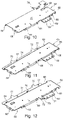
- figure 10 shows this in a perspective view from below Cover component 9 from figure 9 , which can be connected to the base plate 2 by plugging.
- the cover component 9 is designed as a fastening sheet metal 64 with a surface sheet metal section 70 and defined predefined edge shapes.
- the fastening plate 64 serves as a partial housing or to cover the ejector unit 1 on a main side of the ejector unit 1. With the help of the fastening plate 64, the ejector unit 1 is attached to the guide means 52 and/or the drawer 53. Depending on the attachment point of the ejector unit 1 on the piece of furniture 50 and in particular depending on the existing guide means 52, one of the appropriately designed fastening plates 64, 65 or 66 is used.
- Each of the fastening plates 64, 65 and 66 has connecting means which comprise prepared sections for attaching or attaching to the base plate 2, which differ from fastening plate to fastening plate or are different in each case.
- the sections are preferably designed in the edge areas of the respective fastening plate 64, 65 or 66.
- several prepared sections such as six spring tabs 67 are configured on the base plate 2 for connection to a cover component 9 or for interaction with associated matching connection means on the cover component 9 .
- the spring shackles 67 which are bent over like a hook here, can spring in somewhat elastically when the cover component 9 is pushed onto the base plate 2 .
- each spring tab 67 is on an associated window-like one Recess 68 is snapped into the cover component 9, the base plate 2 and the cover component 9 being able to be latched together at several points, or in this case six points, in accordance with the number of spring tabs 67.
- the mounting plates 64, 65 and 66 each have the recesses 68 at the corresponding points. Thus, each of the fastening plates 64, 65 and 66 can be connected to the base plate 2 in the same way.
- the attachment of the ejector unit 1, which is assembled as explained above from the base plate 2 and one of the fastening plates 64, 65 and 66, to a piece of furniture and/or the guide means 52 can be set up using plug-in, screw, snap-in, adhesive and/or other types of connection .
- the fastening plates 64, 65 and 66 have screw holes 69 in common for screwing means, not shown, to pass through for screwing, for example on the underside of the drawer bottom 54.
- the screw holes 69 are present on a first longitudinal side of the fastening plates 64, 65 and 66 on a lug 71, which protrudes laterally via two right-angled bends on the surface sheet metal section 70 offset parallel to the surface sheet metal section 70.
- a further tab 72 with a screw hole 73 is formed on the fastening plate 66 at the level of the surface plate section 70 .
- the connecting means on the cover component 9 include a web 74 here at the fastening plates 65 and 66.
- the web 74 is over the substantial length of the mounting plates 65 and 66 with two spaced laterally projecting tongues 75 designed.
- the web 74 is present on the longitudinal side of the fastening plates 65 and 66 opposite the lug 71 and offset parallel to the surface plate section 70 by bending.
- the tongues 75 can, for example, clamp in correspondingly fitting recesses on the guide means, for example a carcass rail and/or the side wall of the drawer 53.
- Two spaced-apart protruding tongues 76 are also formed on the fastening plate 66 on the associated longitudinal edge of the surface plate section 70 .
- Screw holes 77 are also provided in web 74 .
- the connecting means On the fastening plate 64, which has no web 74, the connecting means have comparatively narrow hook-like tabs 78 and 79.
- the mounting plate 65 is designed to be inserted countersunk into a recessed cut-out on the underside of the drawer bottom 54 . Therefore, the web 74 is offset further according to the depth of the milled cut-out to the surface sheet metal section 70 . As a result, the tongues 75 are formed at the level of the underside of the drawer bottom for engagement in associated areas.
- the ejector unit 1 can then, for example, be completely lowered on the drawer bottom 54.
- connection of the ejector unit 1 by means of the tongues 75, 76 and the tabs 78, 79 is preferably carried out without tools.
Landscapes
- Engineering & Computer Science (AREA)
- Mechanical Engineering (AREA)
- Drawers Of Furniture (AREA)
- Closing And Opening Devices For Wings, And Checks For Wings (AREA)
Claims (10)
- Dispositif (1) pour déplacer une partie de meuble mobile (53) dans une direction d'ouverture de la partie de meuble (53) par rapport à un corps de meuble (51) d'un meuble (50), la partie de meuble mobile (53) pouvant être amenée par l'intermédiaire de moyens de guidage (52) dans la direction d'ouverture et dans une direction de fermeture opposée à la direction d'ouverture, le dispositif (1) comprenant un composant de base (2) sur lequel un accumulateur de force (3) est présent, de telle sorte qu'avec le dispositif (1) monté, la partie de meuble mobile (53) peut être amenée dans la direction d'ouverture de la partie de meuble mobile (53) sous l'effet de l'accumulateur de force (3), un composant de recouvrement séparé (9) du dispositif (1), réalisé de manière à s'adapter au composant de base (2), étant présent, qui recouvre le composant de base (2), des moyens de liaison étant réalisés sur le composant de recouvrement (9) de telle sorte qu'une liaison du dispositif (1) à une section opposée sur le meuble (50) et/ou les moyens de guidage (52) peut être mise en place avec les moyens de liaison présents sur le composant de recouvrement (9), le composant de recouvrement (9) présentant une section plate (70) qui s'étend sur une étendue essentielle du composant de recouvrement (9), le composant de recouvrement (9) présentant une section de bord ayant un contour faisant saillie vers l'extérieur par rapport à des sections de bord voisines, la section de bord en saillie servant à relier le dispositif à la section opposée et la section de bord se raccordant par un repliement à la section plate (70) du composant de recouvrement (9), caractérisé en ce que la section de bord ayant le contour faisant saillie vers l'extérieur se raccorde à la section plate (70) par l'intermédiaire de deux repliements à angle droit et donc en décalage parallèlement à la section plate (70), et la section de bord repliée du composant de recouvrement recouvrant un petit côté du composant de base.
- Dispositif selon la revendication 1, caractérisé en ce que le composant de recouvrement (9) présente un côté d'appui, qui est réalisé pour un appui plat sur une surface de fixation du meuble (50) lorsque le dispositif (1) est monté sur le meuble (50).
- Dispositif selon l'une quelconque des revendications précédentes, caractérisé en ce que le composant de recouvrement (9) est conçu pour recouvrir au moins presque complètement un côté principal du composant de base (2).
- Dispositif selon l'une quelconque des revendications précédentes, caractérisé en ce que les petits côtés du composant de base (2) sont recouverts par une section de bord repliée du composant de recouvrement (9) .
- Dispositif selon l'une quelconque des revendications précédentes, caractérisé en ce que les moyens de liaison sur le composant de recouvrement (9) sont réalisés de telle sorte qu'une liaison du dispositif (1) à une section opposée sur le meuble (50) et/ou les moyens de guidage (52) peut être mise en place sans outil.
- Dispositif selon l'une quelconque des revendications précédentes, caractérisé en ce que le composant de recouvrement (9) et le composant de base (2) sont adaptés l'un à l'autre de telle sorte qu'à l'état relié du composant de recouvrement (9) et du composant de base (2), une section (16, 8, 24) du composant de base (2) dépasse vers l'extérieur sur un petit côté du dispositif (1).
- Dispositif selon l'une quelconque des revendications précédentes, caractérisé en ce que les moyens de liaison sont réalisés pour une liaison amovible aux moyens de guidage (52) de la partie de meuble mobile (53) .
- Dispositif selon l'une quelconque des revendications précédentes, caractérisé en ce que le composant de recouvrement (9) est réalisé pour une fixation du dispositif (1) sur un côté inférieur d'un tiroir (53).
- Dispositif selon l'une quelconque des revendications précédentes, caractérisé en ce que le composant de recouvrement (9) est réalisé pour une fixation du dispositif (1) dans la zone d'une zone réalisée en creux sur le meuble (50).
- Meuble (50) comprenant un corps de meuble (51) et une partie de meuble mobile (53), qui peut être amenée par l'intermédiaire de moyens de guidage (52) dans une direction d'ouverture de la partie de meuble (53) et dans une direction de fermeture opposée à la direction d'ouverture par rapport au corps de meuble (51), un dispositif (1) selon l'une quelconque des revendications précédentes étant prévu.
Applications Claiming Priority (1)
| Application Number | Priority Date | Filing Date | Title |
|---|---|---|---|
| DE202015104438.0U DE202015104438U1 (de) | 2015-08-21 | 2015-08-21 | Vorrichtung zum Bewegen eines bewegbaren Möbelteils und Möbel |
Publications (2)
| Publication Number | Publication Date |
|---|---|
| EP3132713A1 EP3132713A1 (fr) | 2017-02-22 |
| EP3132713B1 true EP3132713B1 (fr) | 2022-07-06 |
Family
ID=56551271
Family Applications (1)
| Application Number | Title | Priority Date | Filing Date |
|---|---|---|---|
| EP16181470.2A Active EP3132713B1 (fr) | 2015-08-21 | 2016-07-27 | Dispositif destine a deplacer un element de meuble mobile |
Country Status (4)
| Country | Link |
|---|---|
| US (1) | US9945166B2 (fr) |
| EP (1) | EP3132713B1 (fr) |
| DE (1) | DE202015104438U1 (fr) |
| ES (1) | ES2927974T3 (fr) |
Families Citing this family (9)
| Publication number | Priority date | Publication date | Assignee | Title |
|---|---|---|---|---|
| DE202015104434U1 (de) * | 2015-08-21 | 2016-12-29 | Grass Gmbh | Vorrichtung zum Bewegen eines bewegbaren Möbelteils sowie Möbel mit einer Vorrichtung zum Bewegen eines bewegbaren Möbelteils |
| DE202015104439U1 (de) * | 2015-08-21 | 2016-11-22 | Grass Gmbh | Vorrichtung zum Bewegen eines bewegbaren Möbelteils und Möbel |
| DE202015104435U1 (de) * | 2015-08-21 | 2016-11-22 | Grass Gmbh | Vorrichtung zum Bewegen eines bewegbaren Möbelteils in eine Öffnungsrichtung in Bezug zu einem Möbelkorpus eines Möbels |
| DE202015106773U1 (de) * | 2015-12-14 | 2017-03-15 | Grass Gmbh | Auswerferanordnung für ein bewegbares Möbelteil |
| DE102017123613A1 (de) * | 2017-10-11 | 2019-04-11 | Paul Hettich Gmbh & Co. Kg | Einzugsvorrichtung und Verfahren zum Öffnen und Schließen eines bewegbaren Möbelteils |
| DE102017128747B4 (de) * | 2017-12-04 | 2022-09-01 | Grass Gmbh | Bewegungsmechanismus für ein Führungssystem |
| AT523798B1 (de) * | 2020-05-07 | 2025-03-15 | Blum Gmbh Julius | Möbelantrieb |
| AT523828B1 (de) * | 2020-07-16 | 2021-12-15 | Blum Gmbh Julius | Möbelbeschlag zur Lagerung eines Möbelteils |
| AT524381B1 (de) * | 2020-10-22 | 2022-07-15 | Blum Gmbh Julius | Möbelantrieb zum Bewegen eines relativ zu einem Möbelkorpus bewegbar gelagerten Möbelteiles |
Citations (2)
| Publication number | Priority date | Publication date | Assignee | Title |
|---|---|---|---|---|
| WO2007087656A1 (fr) * | 2006-01-31 | 2007-08-09 | Julius Blum Gmbh | Mecanisme d'entrainement d'un element de meuble monte a deplacement sur un meuble |
| DE102010031940A1 (de) * | 2009-09-04 | 2011-03-10 | Julius Blum Gmbh | Ausziehführung für Schubladen |
Family Cites Families (10)
| Publication number | Priority date | Publication date | Assignee | Title |
|---|---|---|---|---|
| DE10157754A1 (de) * | 2001-11-27 | 2003-06-26 | Grass Gmbh Hoechst | Vorrichtung zum Öffnen und Schließen eines beweglichen Möbelteils |
| DE202005004336U1 (de) * | 2005-03-17 | 2005-06-23 | Hettich-Heinze Gmbh & Co. Kg | Selbsteinzugsvorrichtung für bewegliche Möbelteile |
| AT508139B1 (de) * | 2009-09-04 | 2010-11-15 | Blum Gmbh Julius | Möbelantrieb mit touch-latch-vorrichtung |
| DE102010036903B4 (de) * | 2010-02-26 | 2020-09-10 | Paul Hettich Gmbh & Co. Kg | Ausstoßvorrichtung und Auszugssystem |
| DE102010061160B4 (de) | 2010-12-10 | 2023-10-26 | Hettich-Heinze Gmbh & Co. Kg | Schließ- und Dämpfungsvorrichtung für bewegbare Möbelteile |
| AT511964B1 (de) * | 2011-12-27 | 2013-04-15 | Blum Gmbh Julius | Antriebsvorrichtung für ein bewegbares möbelteil |
| AT512165B1 (de) | 2011-12-27 | 2013-06-15 | Blum Gmbh Julius | Antriebsvorrichtung für ein bewegbares möbelteil |
| AT514065B1 (de) * | 2013-04-12 | 2014-10-15 | Blum Gmbh Julius | Antriebsvorrichtung für ein bewegbares Möbelteil |
| AT514141B1 (de) * | 2013-04-12 | 2015-08-15 | Blum Gmbh Julius | Antriebsvorrichtung für ein bewegbares Möbelteil |
| AT515040B1 (de) * | 2013-10-25 | 2017-12-15 | Blum Gmbh Julius | Antriebsvorrichtung für ein bewegbares Möbelteil |
-
2015
- 2015-08-21 DE DE202015104438.0U patent/DE202015104438U1/de not_active Expired - Lifetime
-
2016
- 2016-07-27 ES ES16181470T patent/ES2927974T3/es active Active
- 2016-07-27 EP EP16181470.2A patent/EP3132713B1/fr active Active
- 2016-08-16 US US15/238,006 patent/US9945166B2/en active Active
Patent Citations (2)
| Publication number | Priority date | Publication date | Assignee | Title |
|---|---|---|---|---|
| WO2007087656A1 (fr) * | 2006-01-31 | 2007-08-09 | Julius Blum Gmbh | Mecanisme d'entrainement d'un element de meuble monte a deplacement sur un meuble |
| DE102010031940A1 (de) * | 2009-09-04 | 2011-03-10 | Julius Blum Gmbh | Ausziehführung für Schubladen |
Also Published As
| Publication number | Publication date |
|---|---|
| EP3132713A1 (fr) | 2017-02-22 |
| ES2927974T3 (es) | 2022-11-14 |
| US9945166B2 (en) | 2018-04-17 |
| DE202015104438U1 (de) | 2016-11-22 |
| US20170049232A1 (en) | 2017-02-23 |
Similar Documents
| Publication | Publication Date | Title |
|---|---|---|
| EP3132713B1 (fr) | Dispositif destine a deplacer un element de meuble mobile | |
| EP3132717B1 (fr) | Dispositif destiné a déplacer un élément mobile de meuble | |
| EP3133230B1 (fr) | Dispositif destine au deplacement d'un element de meuble et meuble | |
| EP1690473B1 (fr) | Système touch-latch pour des meubles avec des pièces de meuble qui bougent relativement les unes par rapport aux autres, en particulier des tiroirs de meubles, des portes de meubles ou des clapets de meubles | |
| EP3141153B1 (fr) | Dispositif de deplacement d'un element de meuble mobile dans un sens d'ouverture par rapport a un corps d'un meuble | |
| AT508515B1 (de) | Auszugsführung | |
| EP3132716B1 (fr) | Dispositif destine a deplacer un element de meuble mobile | |
| EP3132718B1 (fr) | Dispositif destine a deplacer un element de meuble mobile | |
| EP2656749B1 (fr) | Dispositif d'éjection et dispositif de poussée | |
| WO2013059847A1 (fr) | Verrouillage synchronisé pour une partie mobile de meuble | |
| EP3133232B1 (fr) | Dispositif de deplacement d'un element de meuble mobile et meuble comprenant un dispositif de deplacement d'un element de meuble mobile | |
| EP3132715B1 (fr) | Dispositif de deplacement d'un element de meuble mobile dans un sens d'ouverture par rapport a un corps du meuble | |
| DE202005002433U1 (de) | Touch-Latch System für Möbel mit zueinander relativ bewegbaren Möbelteilen, insbesondere Möbelschubladen, Möbeltüren oder Möbelklappe | |
| EP3132712B1 (fr) | Dispositif de deplacement d'un element de meuble mobile dans un sens d'ouverture par rapport a un corps d'un meuble | |
| EP3132714B1 (fr) | Dispositif de déplacement d'un élément de meuble mobile dans un sens d'ouverture par rapport à un corps d'un meuble | |
| EP3684223B1 (fr) | Dispositif d'accouplement destiné à un tiroir à encliquetage postérieur | |
| EP2713822A1 (fr) | Ensemble coulissant | |
| EP3147440B1 (fr) | Dispositif d'insertion pour portes coulissantes | |
| DE202017103117U1 (de) | Vorrichtung zur Bewegungsbeeinflussung eines Möbelteils und Möbel | |
| EP3769645B1 (fr) | Dispositif de déplacement d'un élément de meuble mobile dans un sens d'ouverture par rapport à un corps d'un meuble | |
| EP4133973B1 (fr) | Dispositif et meuble doté d'une partie de meuble | |
| EP3406163A1 (fr) | Dispositif destiné à déplacer une partie de meuble mobile | |
| DE202008008753U1 (de) | Vorrichtung zum Bewegen eines bewegbaren Möbelteils relativ zu einem feststehenden Möbelteil |
Legal Events
| Date | Code | Title | Description |
|---|---|---|---|
| PUAI | Public reference made under article 153(3) epc to a published international application that has entered the european phase |
Free format text: ORIGINAL CODE: 0009012 |
|
| STAA | Information on the status of an ep patent application or granted ep patent |
Free format text: STATUS: THE APPLICATION HAS BEEN PUBLISHED |
|
| AK | Designated contracting states |
Kind code of ref document: A1 Designated state(s): AL AT BE BG CH CY CZ DE DK EE ES FI FR GB GR HR HU IE IS IT LI LT LU LV MC MK MT NL NO PL PT RO RS SE SI SK SM TR |
|
| AX | Request for extension of the european patent |
Extension state: BA ME |
|
| STAA | Information on the status of an ep patent application or granted ep patent |
Free format text: STATUS: REQUEST FOR EXAMINATION WAS MADE |
|
| 17P | Request for examination filed |
Effective date: 20170809 |
|
| RBV | Designated contracting states (corrected) |
Designated state(s): AL AT BE BG CH CY CZ DE DK EE ES FI FR GB GR HR HU IE IS IT LI LT LU LV MC MK MT NL NO PL PT RO RS SE SI SK SM TR |
|
| STAA | Information on the status of an ep patent application or granted ep patent |
Free format text: STATUS: EXAMINATION IS IN PROGRESS |
|
| 17Q | First examination report despatched |
Effective date: 20190220 |
|
| GRAP | Despatch of communication of intention to grant a patent |
Free format text: ORIGINAL CODE: EPIDOSNIGR1 |
|
| STAA | Information on the status of an ep patent application or granted ep patent |
Free format text: STATUS: GRANT OF PATENT IS INTENDED |
|
| INTG | Intention to grant announced |
Effective date: 20220210 |
|
| GRAS | Grant fee paid |
Free format text: ORIGINAL CODE: EPIDOSNIGR3 |
|
| GRAA | (expected) grant |
Free format text: ORIGINAL CODE: 0009210 |
|
| STAA | Information on the status of an ep patent application or granted ep patent |
Free format text: STATUS: THE PATENT HAS BEEN GRANTED |
|
| AK | Designated contracting states |
Kind code of ref document: B1 Designated state(s): AL AT BE BG CH CY CZ DE DK EE ES FI FR GB GR HR HU IE IS IT LI LT LU LV MC MK MT NL NO PL PT RO RS SE SI SK SM TR |
|
| REG | Reference to a national code |
Ref country code: AT Ref legal event code: REF Ref document number: 1502226 Country of ref document: AT Kind code of ref document: T Effective date: 20220715 Ref country code: CH Ref legal event code: EP |
|
| REG | Reference to a national code |
Ref country code: DE Ref legal event code: R096 Ref document number: 502016015038 Country of ref document: DE |
|
| REG | Reference to a national code |
Ref country code: IE Ref legal event code: FG4D Free format text: LANGUAGE OF EP DOCUMENT: GERMAN |
|
| REG | Reference to a national code |
Ref country code: LT Ref legal event code: MG9D |
|
| REG | Reference to a national code |
Ref country code: NL Ref legal event code: MP Effective date: 20220706 |
|
| REG | Reference to a national code |
Ref country code: ES Ref legal event code: FG2A Ref document number: 2927974 Country of ref document: ES Kind code of ref document: T3 Effective date: 20221114 |
|
| PG25 | Lapsed in a contracting state [announced via postgrant information from national office to epo] |
Ref country code: SE Free format text: LAPSE BECAUSE OF FAILURE TO SUBMIT A TRANSLATION OF THE DESCRIPTION OR TO PAY THE FEE WITHIN THE PRESCRIBED TIME-LIMIT Effective date: 20220706 Ref country code: RS Free format text: LAPSE BECAUSE OF FAILURE TO SUBMIT A TRANSLATION OF THE DESCRIPTION OR TO PAY THE FEE WITHIN THE PRESCRIBED TIME-LIMIT Effective date: 20220706 Ref country code: PT Free format text: LAPSE BECAUSE OF FAILURE TO SUBMIT A TRANSLATION OF THE DESCRIPTION OR TO PAY THE FEE WITHIN THE PRESCRIBED TIME-LIMIT Effective date: 20221107 Ref country code: NO Free format text: LAPSE BECAUSE OF FAILURE TO SUBMIT A TRANSLATION OF THE DESCRIPTION OR TO PAY THE FEE WITHIN THE PRESCRIBED TIME-LIMIT Effective date: 20221006 Ref country code: NL Free format text: LAPSE BECAUSE OF FAILURE TO SUBMIT A TRANSLATION OF THE DESCRIPTION OR TO PAY THE FEE WITHIN THE PRESCRIBED TIME-LIMIT Effective date: 20220706 Ref country code: LV Free format text: LAPSE BECAUSE OF FAILURE TO SUBMIT A TRANSLATION OF THE DESCRIPTION OR TO PAY THE FEE WITHIN THE PRESCRIBED TIME-LIMIT Effective date: 20220706 Ref country code: LT Free format text: LAPSE BECAUSE OF FAILURE TO SUBMIT A TRANSLATION OF THE DESCRIPTION OR TO PAY THE FEE WITHIN THE PRESCRIBED TIME-LIMIT Effective date: 20220706 Ref country code: FI Free format text: LAPSE BECAUSE OF FAILURE TO SUBMIT A TRANSLATION OF THE DESCRIPTION OR TO PAY THE FEE WITHIN THE PRESCRIBED TIME-LIMIT Effective date: 20220706 |
|
| PG25 | Lapsed in a contracting state [announced via postgrant information from national office to epo] |
Ref country code: PL Free format text: LAPSE BECAUSE OF FAILURE TO SUBMIT A TRANSLATION OF THE DESCRIPTION OR TO PAY THE FEE WITHIN THE PRESCRIBED TIME-LIMIT Effective date: 20220706 Ref country code: IS Free format text: LAPSE BECAUSE OF FAILURE TO SUBMIT A TRANSLATION OF THE DESCRIPTION OR TO PAY THE FEE WITHIN THE PRESCRIBED TIME-LIMIT Effective date: 20221106 Ref country code: HR Free format text: LAPSE BECAUSE OF FAILURE TO SUBMIT A TRANSLATION OF THE DESCRIPTION OR TO PAY THE FEE WITHIN THE PRESCRIBED TIME-LIMIT Effective date: 20220706 Ref country code: GR Free format text: LAPSE BECAUSE OF FAILURE TO SUBMIT A TRANSLATION OF THE DESCRIPTION OR TO PAY THE FEE WITHIN THE PRESCRIBED TIME-LIMIT Effective date: 20221007 |
|
| REG | Reference to a national code |
Ref country code: CH Ref legal event code: PL |
|
| REG | Reference to a national code |
Ref country code: BE Ref legal event code: MM Effective date: 20220731 |
|
| REG | Reference to a national code |
Ref country code: DE Ref legal event code: R097 Ref document number: 502016015038 Country of ref document: DE |
|
| PG25 | Lapsed in a contracting state [announced via postgrant information from national office to epo] |
Ref country code: SM Free format text: LAPSE BECAUSE OF FAILURE TO SUBMIT A TRANSLATION OF THE DESCRIPTION OR TO PAY THE FEE WITHIN THE PRESCRIBED TIME-LIMIT Effective date: 20220706 Ref country code: RO Free format text: LAPSE BECAUSE OF FAILURE TO SUBMIT A TRANSLATION OF THE DESCRIPTION OR TO PAY THE FEE WITHIN THE PRESCRIBED TIME-LIMIT Effective date: 20220706 Ref country code: MC Free format text: LAPSE BECAUSE OF FAILURE TO SUBMIT A TRANSLATION OF THE DESCRIPTION OR TO PAY THE FEE WITHIN THE PRESCRIBED TIME-LIMIT Effective date: 20220706 Ref country code: LU Free format text: LAPSE BECAUSE OF NON-PAYMENT OF DUE FEES Effective date: 20220727 Ref country code: LI Free format text: LAPSE BECAUSE OF NON-PAYMENT OF DUE FEES Effective date: 20220731 Ref country code: DK Free format text: LAPSE BECAUSE OF FAILURE TO SUBMIT A TRANSLATION OF THE DESCRIPTION OR TO PAY THE FEE WITHIN THE PRESCRIBED TIME-LIMIT Effective date: 20220706 Ref country code: CZ Free format text: LAPSE BECAUSE OF FAILURE TO SUBMIT A TRANSLATION OF THE DESCRIPTION OR TO PAY THE FEE WITHIN THE PRESCRIBED TIME-LIMIT Effective date: 20220706 Ref country code: CH Free format text: LAPSE BECAUSE OF NON-PAYMENT OF DUE FEES Effective date: 20220731 |
|
| PLBE | No opposition filed within time limit |
Free format text: ORIGINAL CODE: 0009261 |
|
| STAA | Information on the status of an ep patent application or granted ep patent |
Free format text: STATUS: NO OPPOSITION FILED WITHIN TIME LIMIT |
|
| PG25 | Lapsed in a contracting state [announced via postgrant information from national office to epo] |
Ref country code: SK Free format text: LAPSE BECAUSE OF FAILURE TO SUBMIT A TRANSLATION OF THE DESCRIPTION OR TO PAY THE FEE WITHIN THE PRESCRIBED TIME-LIMIT Effective date: 20220706 Ref country code: EE Free format text: LAPSE BECAUSE OF FAILURE TO SUBMIT A TRANSLATION OF THE DESCRIPTION OR TO PAY THE FEE WITHIN THE PRESCRIBED TIME-LIMIT Effective date: 20220706 Ref country code: BE Free format text: LAPSE BECAUSE OF NON-PAYMENT OF DUE FEES Effective date: 20220731 |
|
| 26N | No opposition filed |
Effective date: 20230411 |
|
| GBPC | Gb: european patent ceased through non-payment of renewal fee |
Effective date: 20221006 |
|
| PG25 | Lapsed in a contracting state [announced via postgrant information from national office to epo] |
Ref country code: AL Free format text: LAPSE BECAUSE OF FAILURE TO SUBMIT A TRANSLATION OF THE DESCRIPTION OR TO PAY THE FEE WITHIN THE PRESCRIBED TIME-LIMIT Effective date: 20220706 |
|
| PG25 | Lapsed in a contracting state [announced via postgrant information from national office to epo] |
Ref country code: IE Free format text: LAPSE BECAUSE OF NON-PAYMENT OF DUE FEES Effective date: 20220727 Ref country code: FR Free format text: LAPSE BECAUSE OF NON-PAYMENT OF DUE FEES Effective date: 20220906 |
|
| PG25 | Lapsed in a contracting state [announced via postgrant information from national office to epo] |
Ref country code: SI Free format text: LAPSE BECAUSE OF FAILURE TO SUBMIT A TRANSLATION OF THE DESCRIPTION OR TO PAY THE FEE WITHIN THE PRESCRIBED TIME-LIMIT Effective date: 20220706 |
|
| PG25 | Lapsed in a contracting state [announced via postgrant information from national office to epo] |
Ref country code: GB Free format text: LAPSE BECAUSE OF NON-PAYMENT OF DUE FEES Effective date: 20221006 |
|
| PG25 | Lapsed in a contracting state [announced via postgrant information from national office to epo] |
Ref country code: HU Free format text: LAPSE BECAUSE OF FAILURE TO SUBMIT A TRANSLATION OF THE DESCRIPTION OR TO PAY THE FEE WITHIN THE PRESCRIBED TIME-LIMIT; INVALID AB INITIO Effective date: 20160727 |
|
| PG25 | Lapsed in a contracting state [announced via postgrant information from national office to epo] |
Ref country code: MK Free format text: LAPSE BECAUSE OF FAILURE TO SUBMIT A TRANSLATION OF THE DESCRIPTION OR TO PAY THE FEE WITHIN THE PRESCRIBED TIME-LIMIT Effective date: 20220706 Ref country code: CY Free format text: LAPSE BECAUSE OF FAILURE TO SUBMIT A TRANSLATION OF THE DESCRIPTION OR TO PAY THE FEE WITHIN THE PRESCRIBED TIME-LIMIT Effective date: 20220706 |
|
| PG25 | Lapsed in a contracting state [announced via postgrant information from national office to epo] |
Ref country code: BG Free format text: LAPSE BECAUSE OF FAILURE TO SUBMIT A TRANSLATION OF THE DESCRIPTION OR TO PAY THE FEE WITHIN THE PRESCRIBED TIME-LIMIT Effective date: 20220706 |
|
| PG25 | Lapsed in a contracting state [announced via postgrant information from national office to epo] |
Ref country code: MT Free format text: LAPSE BECAUSE OF FAILURE TO SUBMIT A TRANSLATION OF THE DESCRIPTION OR TO PAY THE FEE WITHIN THE PRESCRIBED TIME-LIMIT Effective date: 20220706 |
|
| REG | Reference to a national code |
Ref country code: DE Ref legal event code: R082 Ref document number: 502016015038 Country of ref document: DE Representative=s name: RAVENSPAT PATENTANWAELTE PARTNERSCHAFT MBB, DE |
|
| PGFP | Annual fee paid to national office [announced via postgrant information from national office to epo] |
Ref country code: ES Payment date: 20250808 Year of fee payment: 10 |
|
| PGFP | Annual fee paid to national office [announced via postgrant information from national office to epo] |
Ref country code: DE Payment date: 20250724 Year of fee payment: 10 |
|
| PGFP | Annual fee paid to national office [announced via postgrant information from national office to epo] |
Ref country code: TR Payment date: 20250722 Year of fee payment: 10 Ref country code: IT Payment date: 20250715 Year of fee payment: 10 |
|
| PGFP | Annual fee paid to national office [announced via postgrant information from national office to epo] |
Ref country code: AT Payment date: 20250723 Year of fee payment: 10 |