EP4133973B1 - Dispositif et meuble doté d'une partie de meuble - Google Patents
Dispositif et meuble doté d'une partie de meuble Download PDFInfo
- Publication number
- EP4133973B1 EP4133973B1 EP22188639.3A EP22188639A EP4133973B1 EP 4133973 B1 EP4133973 B1 EP 4133973B1 EP 22188639 A EP22188639 A EP 22188639A EP 4133973 B1 EP4133973 B1 EP 4133973B1
- Authority
- EP
- European Patent Office
- Prior art keywords
- ejector
- synchronization
- furniture
- movement
- opening direction
- Prior art date
- Legal status (The legal status is an assumption and is not a legal conclusion. Google has not performed a legal analysis and makes no representation as to the accuracy of the status listed.)
- Active
Links
Images




Classifications
-
- A—HUMAN NECESSITIES
- A47—FURNITURE; DOMESTIC ARTICLES OR APPLIANCES; COFFEE MILLS; SPICE MILLS; SUCTION CLEANERS IN GENERAL
- A47B—TABLES; DESKS; OFFICE FURNITURE; CABINETS; DRAWERS; GENERAL DETAILS OF FURNITURE
- A47B88/00—Drawers for tables, cabinets or like furniture; Guides for drawers
- A47B88/40—Sliding drawers; Slides or guides therefor
- A47B88/44—Sequencing or synchronisation of drawer slides or functional units
- A47B88/45—Synchronisation of cooperating drawer slides, i.e. with a coordination of the rail movement of different drawer slides
-
- A—HUMAN NECESSITIES
- A47—FURNITURE; DOMESTIC ARTICLES OR APPLIANCES; COFFEE MILLS; SPICE MILLS; SUCTION CLEANERS IN GENERAL
- A47B—TABLES; DESKS; OFFICE FURNITURE; CABINETS; DRAWERS; GENERAL DETAILS OF FURNITURE
- A47B88/00—Drawers for tables, cabinets or like furniture; Guides for drawers
- A47B88/40—Sliding drawers; Slides or guides therefor
- A47B88/453—Actuated drawers
- A47B88/46—Actuated drawers operated by mechanically-stored energy, e.g. by springs
- A47B88/463—Actuated drawers operated by mechanically-stored energy, e.g. by springs self-opening
Definitions
- Devices for moving a movable furniture part are known, in particular devices which are attached, for example, to guide means for the guided movement of the movable furniture part or to the associated furniture.
- the known devices generally comprise a force accumulator with which the movable furniture part is supported during an opening and/or closing movement relative to the furniture body. To eject the furniture part from a closed position in the opening direction, the device is first triggered from a standby position with the force accumulator charged in order to activate the force accumulator.
- the object of the present invention is to improve a device for moving a movable furniture part with the aid of a force accumulator, in particular with regard to a safe establishment of a standby position of the device.
- the invention is based on a device for moving a furniture part in an opening direction relative to a furniture body of a piece of furniture, wherein the furniture part is guided into the Opening direction and in a closing direction opposite to the opening direction.
- the device is in particular an ejection device such as a drawer or door or flap ejection device with touch-latch function for the drawer or the flap of the furniture.
- the guide means are preferably known rail guides that are designed as partial or full extension, or flap fittings or door fittings.
- the device can be functionally coupled to or comprise an automatic retraction mechanism for the dampened, power-assisted, gentle or soft retraction of the furniture part or the drawer, the door or the flap or the door into the closed position of the drawer or flap or door.
- the device has a chargeable energy accumulator and an ejector which can be driven in the opening direction under the effect of the discharging energy accumulator, wherein the energy accumulator can be locked in the charged state, so that with the device mounted on the furniture, after unlocking the charged energy accumulator, the furniture part can be moved from a closed position on the furniture body in the opening direction, wherein the ejector can be coupled in movement to the furniture part, wherein the energy accumulator can be charged with a movement of the ejector back in the closing direction, and wherein a synchronization element of the device is provided, which can be coupled to synchronize an unlocking of the charged energy accumulator of the device with a synchronization element of another corresponding device provided on the furniture for moving the furniture part in the opening direction.
- the synchronization relates in particular to the touch latch function in a comparatively wide furniture part on which two identical ejection devices spaced apart in the width direction are present.
- the two devices work together when ejecting the furniture part, whereby their energy storage devices together provide an additive total ejection force on the furniture part.
- a non-common Triggering both devices means that only the force of one of the two energy storage devices is used to eject the furniture. This can mean that the furniture part is not ejected, particularly when the furniture is fully loaded.
- the synchronization element of the device is reversibly adjustable in the opening direction and in the closing direction, wherein after unlocking the loaded energy storage device, the synchronization element is moved from a starting position in the opening direction to an adjustment position, so that a synchronization element can be moved for synchronization, wherein stop means are provided for returning the synchronization element to the starting position, with which a movement coupling in the closing direction can be set up between the ejector and the synchronization element, so that coupled with the movement of the ejector in the closing direction, when the energy storage device is reloaded, the synchronization element is moved from the adjustment position or from a position between the adjustment position and the starting position in the closing direction to the starting position.
- the synchronization element if it has not already reached the start position, is safely and forcibly returned to the start position by means of a mechanical stop function.
- the ejector moves in the closing direction and charges the energy storage device. This is the case when the furniture part is closed.
- the ejector is also moved in the closing direction, e.g. mechanically firmly coupled, by the closing furniture part, and the energy storage device is thereby also charged.
- a part of the device that is coupled in motion with the ejector such as an ejector, takes the synchronization element with it for a while when the furniture part is closed, for example to the start position.
- the synchronization element needs to be carried along by the lifting devices when a tensile force acts on the synchronization element in the closing direction, which is then sufficient to cause the remaining movement to the starting position.
- the furniture part is then closed for the next ejection movement and the energy storage device is charged and the synchronization element is in the starting position required for synchronization.
- the invention particularly solves the problem whereby, for example due to component tolerances, material changes or other influences, the movement of the synchronization element from an adjustment position back to the start position does not take place or does not take place completely, despite the presence of a return force, e.g. through a return element such as a return spring.
- a return force e.g. through a return element such as a return spring.
- a return element acts on the synchronization element and provides a permanently established return force in the direction of the start position on the synchronization element in order to bring the synchronization element into the start position.
- the return element is preferably a return energy storage device or a tensile force element such as a tension spring, for example a coil spring, which is pre-tensioned or acts on the synchronization element in a pulling manner in the closing direction. Since the return force is designed to be comparatively weak compared to the energy storage device for the ejection movement of the furniture part, since this ejection process has to be overcome by the energy accumulator to eject the furniture part and therefore as little force component as possible should be formed against the ejection force, it can regularly or spontaneously happen that the restoring force is not sufficient or is not always sufficient to pull the synchronization element back to the start position due to frictional forces on the synchronization element, for example.
- a tensile force element such as a tension spring, for example a coil spring
- the slings are used to forcibly move the synchronization element into the start position at the latest when the furniture part and thus the ejector is moved in the closing direction.
- the slings act by means of the slings, which in particular overcomes static friction effects, in such a way that the restoring force provided by the restoring element is then sufficient to move the synchronization element into the start position through the effect of the restoring element alone. Otherwise, the slings act accordingly, e.g. even if excessive frictional resistance should have a braking effect on the movement of the synchronization element into the start position.
- a permanent connection is established between the return element and the synchronization element.
- the return element in addition to the stop means, the return element also acts when the furniture part is closed to bring the synchronization element into the starting position. For example, it is possible for the effective return forces to be superimposed on the synchronization element.
- the return element is designed to apply a tensile force in the closing direction to the synchronization element.
- This makes it possible to apply a secure force to reset the synchronization element, for example with a slightly pre-tensioned helical tension spring.
- the level of the tensile force is lower, preferably several times lower, than the level of the ejection force of the Energy storage device.
- the tensile force acts permanently in the closing direction on the synchronization device.
- stop means comprise a stop surface on the synchronization element, which comes into contact with a counter stop surface when the ejector moves in the closing direction.
- stop surfaces that are matched to one another, a flat system for mechanically coupled or secure movement of the synchronization element in the closing direction can be made possible when loading the energy storage device.
- the stop surface and counter stop surface are preferably perpendicular to the direction of movement of the synchronization element.
- the stop means have a projection on an outer contour of a movement element that can be coupled to the ejector.
- a projection can be formed easily and in a space-saving manner.
- the projection has, for example, a stop surface that is transverse and perpendicular to the direction of movement of the synchronization element.
- an advantageous modification of the invention is that the energy storage device engages an ejector which can be moved in the closing and opening directions and which, after unlocking the charged energy storage device, takes the ejector in the opening direction.
- the ejector is thus moved in accordance with the path required to charge and discharge the energy storage device.
- the ejector on the other hand, can be moved over a larger path, in particular in the opening direction, in order to move the furniture part further in the opening direction, for example after discharging the energy storage device.
- a separate ejector energy storage device can engage the ejector, for example to apply a tensile force acting on the ejector in the opening direction.
- the ejector acts particularly between the ejector and the furniture part.
- Another advantageous variant arises when the lifting devices are arranged between the ejector and the synchronization element. This allows the length along the path in the closing direction and/or the time at which the lifting devices start and end to be set up or determined variably.
- the energy storage device i.e. the energy storage device for ejection
- the energy storage device for ejection has a bearing point that is fixed in position on the device and a bearing point that acts on the ejector.
- the additional stop means in addition to the stop means on the synchronization element are preferably present on the ejector.
- the stop means on the ejector are preferably present on an end section of the ejector that faces the fixed bearing point of the energy storage device, viewed in the longitudinal direction of the ejector or in the direction of movement of the ejector.
- stop means are provided between the ejector and the synchronization element.
- a further advantageous modification is such that, for synchronization, an elongated connecting element is connected to the synchronization element in such a way that a movement of the synchronization element in the opening direction causes a rotary movement in a first direction of rotation of the connecting element.
- the linear movement of the synchronization element is converted into a rotary movement of the connecting element via a suitable gear. transferred.
- the connecting element is preferably connected at its opposite ends in a movement-coupled manner to one of the two synchronization elements.
- the connecting element bridges the distance between the two devices on the furniture.
- a movement of the synchronization element in the closing direction leads to a rotational movement in a second direction of rotation of the connecting element, which is the case, for example, when the synchronization element is reset in the closing direction.
- This also advantageously synchronizes the force effect of the reset elements or the driving movement carried out by the synchronization slide via the stop means.
- the device has a touch-latch function for unlocking the loaded energy storage device.
- This is a tried and tested, user-friendly design.
- the advantage is that no handles are required to pull on the outside of the furniture part to open the furniture part, since with a touch latch function, pressing the furniture part from the outside is sufficient to trigger and unlock the ejection energy storage device and to subsequently close the furniture.
- the invention is also realized as a piece of furniture, with a furniture body and a furniture part that is movable relative to the furniture body via guide means, wherein a device according to one of the above-mentioned embodiments is present.
- the furniture is a drawer furniture or a furniture with a pivoting flap or door if the guide means are designed as a hinged means such as a flap fitting or a door hinge.
- a piece of furniture 50 with a box-shaped furniture body 51 and a drawer 53 movably guided by guide means 52 is shown in Figure 1
- the drawer 53 comprises a drawer bottom 54, a drawer front 55, two opposite side walls 56 and a drawer rear wall 57.
- two identical guide means 52 are provided between each side wall 56 of the drawer 53 and an associated body side wall 58.
- Two identical devices 1, 2 according to the invention are arranged on an underside of the drawer base 54, which serve jointly and synchronously to move or eject the furniture part designed as drawer 53 in the opening direction M1.
- the device 1 serves for the force-assisted ejection of the drawer 53 over a partial section of an opening movement of the drawer 53 from a closed position relative to the furniture body 51 in the opening direction M1 of the drawer 53.
- the drawer 53 is mounted on the furniture body 51 via the guide means 52, for example two similar partial or full extensions, so that it can be moved in the opening direction M1 and in the opposite closing direction M2.
- the device 1 can alternatively be arranged on the furniture body 51 or on the guide means 52 of the furniture 50.
- the device comprises as basic main components a base plate 3, a power unit 4, a latch component 5, an ejector 6 and a power accumulator 7 (see Fig. Fig. 2 ).
- the guide track 8 is formed in the base plate 3.
- a recess 9 is provided in the base plate 3 for receiving a movement element 10, which is preferably acted upon by the energy accumulator 7.
- the movement element 10 can also be referred to as an ejector.
- the energy accumulator 7 comprises at least one coil spring 11, preferably two individually insertable coil springs 11, 12, each of which is fastened at one end to the movement element 10.
- the other ends of the coil springs 11, 12 are advantageously connected to a bearing part 13, wherein the length and thus the preload force of the tensioned coil springs 11, 12 can be adjusted by an operating section 14.
- a spring rod 15 is arranged on the movement element 10, which is guided with a bent end section preferably in a heart curve 16, which is formed in the base plate 3. Furthermore, the spring rod 15 can be moved along the guide slot 17 of the ejector 6. When the spring rod 15 moves along a guide slot 17 in the ejector 6 and/or the heart curve 16 in the base plate 3, a synchronization element designed as a synchronization plate 18 is moved along with it. The synchronization plate 18 can be moved linearly in the direction P1 and P2.
- the synchronization plate 18 is connected to the base plate 3 via a spring 19.
- a synchronization element 18a is set in rotation D1, in the direction of rotation depending on the movement of the synchronization plate 18 in the direction P1 or P2.
- the synchronization element 18a is on the other in the Fig. 15-17 not shown end is connected to the further device 2 or to a synchronization plate 18 of the device 2.
- the base plate 3 is covered by a cover element 20, wherein the cover element 20 forms a surface almost corresponding counter plate, whereby an interior of the device 1 is enclosed on both sides and on the circumferential narrow sides, whereby individual areas are open to the outside.
- the cover element 20 has a control cover 21, which are formed in two parts or in one piece.
- the control cover 21 preferably has a further heart curve (not shown), which in the assembled state preferably provides a guide path corresponding to the heart curve 16 for a further angled end of the spring rod 15 in the base plate 3. This enables a safe guide on both sides for the spring rod ends of the spring rod 15.
- the guide track 8 is designed in the base plate 3 in order to move the latch component 5 along the guide track 8.
- the guide track 8 preferably has two separate guide tracks 8 in the width direction of the base plate, which is aligned perpendicular to the opening and closing movement of the ejector 6.
- the guide track 8 can be divided into two guide areas 22, 23, preferably into exactly two guide areas.
- the first guide area 22 is recessed in the base plate 3 opposite one surface side of the ejector 6.
- the second guide area 23 preferably runs in the opening direction P1 and closing direction P2 of the ejector 6.
- the direction P1 correlates with direction M1 and the direction P2 correlates with direction M2.
- the two guide areas 22, 23 aligned at an angle to each other form, for example, an L-shape, with the longer leg forming the second guide area 23 and the shorter leg forming the first guide area 22.
- FIG. 3 A receptacle in the base plate 3 for a second end of the power unit 4 is visible.
- the first end of the power unit 4 is connected to a connecting section 24 of the latch component 5 (see Fig. 4 ).
- the latch component 5 also has a guide member 25, which can preferably be moved permanently in the second guide region 23 of the guide track 8.
- the guide member 25 is provided in a protruding manner on the latch component 5 and is preferably cylindrical or bolt-like.
- Guide members 25 are preferably provided on both sides of the latch component 5, which can be moved along the guide tracks 8 spaced apart in the width direction.
- the guide member 25 can advantageously be moved in a supporting manner along the second guide region 23 of the guide track 8.
- the latch component 5 also has a guide element 26, which is moved from the first guide region 22 into the second guide region 23 during an opening movement of the ejector 6.
- a hook section 27 of the latch component 5, which is located above the guide element 26 in the direction of the ejector 6, can be pivoted in the direction of the ejector 6.
- the latch component 5 also has a hooking contour 28 which can interact with the ejector 6.
- the hooking contour 28 is preferably aligned transversely to the opening and closing direction of the ejector 6.
- the ejector 6 has a recess 29 on a lower side which is directed towards the base plate 3 (see Fig. 5 ).
- the recess 29 is preferably groove-shaped, with the longitudinal extension L of the recess 29 being aligned in the opening and closing direction of the ejector 6.
- the connecting section 24 of the latch component 5 is preferably accommodated in the recess 29.
- the recess 29 has a surface which is formed in the width direction and height, with an edge contour 30 which can be coupled to and decoupled from the hooking contour 28 of the latch component 5.
- a stop element 31 is formed on the ejector 6, which interacts with the drawer 53 or a drawer rail of the guide means 52. After unlocking the The loaded, locked energy storage device 7 moves the ejector 6 in an opening movement of the movement element 10 and this moves the drawer 53 in the opening direction P1 via the stop element 31 through the force of the loaded energy unit 4 and/or the energy storage device 7. During the closing movement P2, the drawer 53 or a section of the drawer rail presses against the stop element 31 of the ejector 6, whereby the movement element 10 or the ejector and thus the energy storage device 7 acting on the ejector and the energy unit 4 are loaded.
- the latch component 5 is covered from above by the ejector 6 in the closed position.
- the connecting section 24 of the latch component 5 is accommodated in the recess 29 of the ejector 6, whereby the edge contour 30 of the recess 29 does not interact with the hooking contour 28 of the latch component 5.
- the guide element 26 of the latch component 5 is located in the first guide region 22 in the closed position, so that the force unit 4 is tensioned to the maximum.
- the guide member 25 is supported on the guide track 8 of the second guide region 23.
- the spring rod 15 is arranged in an arcuate section of the heart curve 16, whereby a movement of the spring rod 15 in the opening direction P1 is not possible since the synchronization plate 18 blocks this movement (see. Fig. 6 ). A zero position of the device 1 is reached, the drawer 53 rests in the closed position on the furniture body 51.
- the drawer 53 is intentionally opened or ejected from the outside by a user who uses the touch latch function and pushes the drawer 53 or the drawer front 55 of the drawer 53 inwards in the closing direction M2, whereby the ejector 6 moves with the movement element 10 in the closing direction P2.
- the movement element 10 also moves the spring rod 15 in the closing direction P2, whereby the spring rod 15 is no longer blocked by the synchronization plate 18.
- the end of the spring engages around a front side of the synchronization plate 18, which can now be moved in the opening direction P1. This discharges the energy accumulator 7 and the spring rod 15 is moved along the heart curve and a side flank on the synchronization plate 18 in the opening direction P1.
- the synchronization plate 18 and the ejector 6 are also moved in the opening direction P1.
- the drawer 53 is thereby taken along or ejected.
- the first opening position is then reached (see Figure 9 ). In the first opening position, the energy accumulator 7 is discharged.
- the guide element 26 of the latch component 5 is still in the first guide region 22 of the guide track 8 and thus the hook section 27 is not yet deflected in the direction of the ejector 6. Because the edge contour 30 of the recess meets the hooking contour 28 of the latch component 5, the latch component 5 is moved in the opening direction P1, whereby the guide element 26 is moved along the guide track 8 into the second guide region 23.
- the latch component 5 can be pivoted about the guide member 25, which rests on the guide track 8 in the second guide region 23. When the latch component 5 is pivoted, the hook section 27 can be deflected upwards in the direction of the ejector 6, whereby the hook section 27 engages behind an end contour 32 of the ejector 6.
- the power unit 4 can be unloaded. This moves the latch component 5 in the opening direction P1.
- the ejector 6 is also moved in the opening direction P1 because the hook section 27 of the latch component 5 engages behind the ejector 6 until the second opening position is reached (see. Fig. 12 to 14 ).
- the stop element 31 of the ejector 6 moves the drawer 53 in the opening direction P1.
- the power unit 4 is unloaded.
- the edge contour 30 of the recess 29 is in contact with the hooking contour 28 of the latch component 5.
- the guide member 25 and the guide element 26 are located in the second guide region 23 of the guide track 8, with the guide member 25 being horizontally spaced from the guide element 26.
- the guide member 25 is located further forward in the opening direction P1 compared to the guide element 26.
- the spring rod 15 is first moved along a first straight area 33 of the guide slot 17 of the ejector 6.
- the spring rod 15 is fixedly arranged according to a position on the heart curve 16. With further movement in the opening direction P1, the spring rod 15 is moved through a lateral area 34 of the guide slot 17 to the right or in the direction of the power unit 4 and then moved along a second straight area 35.
- the spring rod 15 thus reaches the right section of the heart curve 16 (see. Fig. 12 ) and the synchronization plate 18 can be retracted to its original position by the spring 19.
- the spring rod 15 is first moved along the second straight area 35 of the guide slot 17 until the spring rod 15 rests at the transition between the second straight area 35 and the lateral area 34.
- the spring rod 15 rests at the transition, with a further closing movement of the ejector 6, the spring rod 15 and thus also the movement element 10 with the energy storage device 7 can be moved in the closing direction P2, whereby the energy storage device 7 is charged.
- the spring rod 15 is guided along a right-hand straight section 36 of the heart-shaped curve 16 until the end of this section 36.
- the spring rod 15 then follows the heart-shaped curve 16 and moves to the left in the direction of the spring 19.
- the spring rod 15 thus also reaches the first straight section 33 of the guide slot 17.
- the spring rod 15 is locked in the heart-shaped curve 16, whereby with further closing movement of the ejector 6, the spring rod 15 is moved along the first straight section 33. With further closing movement of the ejector 6, the closed position is reached (see. Fig. 6 ).
- the power unit 4 is loaded directly by the hook section 27 resting on the end contour 32 of the ejector 6 when the ejector 6 is moved in the closing direction P2.
- the guide member 25 and the guide element 26 can be moved along the second guide area 23 of the guide track 8 until the guide element 26 reaches the first guide area 22 and is pivoted downwards.
- the hook section 27 of the latch component 5 no longer rests on the end contour 32 of the ejector 6, so that the ejector 6 can be moved in the closing direction relative to the latch component 5.
- the connecting section 24 of the latch component 5 is moved along the recess 29 of the ejector 6.
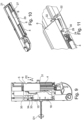
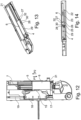
- Fig. 15 clarifies that stop means 37 with a stop surface 38 on the moving element 10 or on the ejector and a stop surface 39 on the synchronization plate 18 are present. According to Fig. 15 the two stop surfaces 38 and 39 are separated from each other by a few millimeters in the direction of movement of the moving element 10 or in the direction P1 or P2. This is because the synchronization plate 18 is retracted into the starting position due to the activated tension spring force of the spring 19 and is ready for a synchronization process.
- the stop means 37 have a projection 10a protruding from an outer contour of the movement element 10 that can be coupled to the ejector 6.
- F1 tensile force
- the Fig. 16 and 17 illustrate the driving contact between the stop surfaces 38 and 39 when the synchronization plate 18 is still in an adjustment position, i.e. remains in this position after a synchronization movement or gets stuck, despite spring 19, which Fig. 16, 17 This can be caused, for example, by friction effects, if the force of the spring 19 is not sufficient to move the synchronization plate 18 from the position in the Fig. 16, 17 shown adjustment position due to e.g.
- the moving element 10 takes the synchronization plate 18 into the starting position.
- the stop surface 38 presses against the stop surface 39 and forces the synchronization plate 18 in the direction of P2.
- the synchronization plate 18 is forcibly returned to the starting position, supported by the force F1.
- the synchronization plate 18 when the drawer is closed and at rest, the synchronization plate 18 is in the start position. Then, the next time the closed drawer is operated using the touch latch function, the synchronization plate 18 can be moved when the loaded energy storage device 7 is unlocked.
Landscapes
- Engineering & Computer Science (AREA)
- Mechanical Engineering (AREA)
- Drawers Of Furniture (AREA)
Claims (8)
- Dispositif (1, 2) pour déplacer une partie de meuble (53) dans une direction d'ouverture par rapport à un corps de meuble (51) d'un meuble (50), la partie de meuble (53) pouvant être déplacée par l'intermédiaire de moyens de guidage (52) dans la direction d'ouverture et dans une direction de fermeture opposée à la direction d'ouverture, le dispositif (1, 2) présentant un accumulateur de force (7) rechargeable et un éjecteur (6) qui peut être entraîné dans la direction d'ouverture sous l'effet de l'accumulateur de force (7) qui se décharge, l'accumulateur de force (7) pouvant être verrouillé à l'état chargé, de telle sorte qu'avec le dispositif (1, 2) monté sur le meuble (50), après un déverrouillage de l'accumulateur de force chargé (7), la partie de meuble (53) peut être déplacée d'une position de fermeture sur le corps de meuble (51) dans la direction d'ouverture, l'éjecteur (6) pouvant être couplé en déplacement avec la partie de meuble (53), l'accumulateur de force (7) pouvant être chargé par un déplacement de l'éjecteur (6) en retour dans la direction de fermeture, et un organe de synchronisation (18) du dispositif (1, 2) étant prévu, qui, pour la synchronisation d'un déverrouillage de l'accumulateur de force chargé (7) du dispositif (1, 2), peut être couplé à un organe de synchronisation (18) d'un autre dispositif (1, 2) correspondant prévu sur le meuble (53) pour déplacer la partie de meuble (53) dans la direction d'ouverture, l'organe de synchronisation (18) du dispositif (1, 2) pouvant être réglé de manière réversible dans la direction d'ouverture et dans la direction de fermeture ; après le déverrouillage de l'accumulateur de force chargé (7), un déplacement de l'organe de synchronisation (18) ayant lieu d'une position de départ dans la direction d'ouverture à une position de réglage, de telle sorte qu'un élément de synchronisation (18a) peut être déplacé pour la synchronisation ; pour un rappel de l'organe de synchronisation (18) dans la position de départ, des moyens de butée (37) étant prévus, avec lesquels un couplage de déplacement dans la direction de fermeture peut être établi entre l'éjecteur (6) et l'organe de synchronisation (18), de telle sorte que, couplé au déplacement de l'éjecteur (6) dans la direction de fermeture, lors d'un nouveau chargement de l'accumulateur de force (7), il se produit un entraînement de l'organe de synchronisation (18) depuis la position de réglage ou depuis une position entre la position de réglage et la position de départ dans la direction de fermeture jusqu'à la position de départ, caractérisé en ce qu'il est prévu un élément de rappel (19), qui agit sur l'organe de synchronisation (18) et fournit une force de rappel établie de manière permanente en direction de la position de départ sur l'organe de synchronisation (18), afin d'amener l'organe de synchronisation (18) dans la position de départ, l'élément de rappel (19) étant réalisé pour appliquer une force de traction dans la direction de fermeture sur l'organe de synchronisation (18) .
- Dispositif selon la revendication 1, caractérisé en ce que les moyens de butée (37) comprennent une surface de butée (39) sur l'organe de synchronisation (18) qui vient en appui contre une contre-surface de butée (38) lorsque l'éjecteur (6) se déplace dans la direction de fermeture.
- Dispositif selon l'une quelconque des revendications précédentes, caractérisé en ce que les moyens de butée (37) présentent une saillie (10a) faisant saillie sur un contour extérieur d'un élément de déplacement (10) pouvant être couplé à l'éjecteur (6).
- Dispositif selon l'une quelconque des revendications précédentes, caractérisé en ce que l'accumulateur de force (7) agit sur un élément de déplacement (10) qui est mobile en translation dans la direction de fermeture et dans la direction d'ouverture et qui entraîne l'éjecteur (6) dans la direction d'ouverture après le déverrouillage de l'accumulateur de force chargé (7).
- Dispositif selon l'une quelconque des revendications précédentes, caractérisé en ce que les moyens de butée (37) sont réalisés entre l'élément de déplacement (10) et l'organe de synchronisation (18).
- Dispositif selon l'une quelconque des revendications précédentes, caractérisé en ce que, pour la synchronisation, un élément de liaison allongé (18a) est relié à l'organe de synchronisation (18) de telle sorte qu'un déplacement de l'organe de synchronisation (18) dans la direction d'ouverture provoque un déplacement de rotation dans une première direction de rotation de l'élément de liaison (18a).
- Dispositif selon l'une quelconque des revendications précédentes, caractérisé en ce que le dispositif (1, 2) présente une fonction de verrou tactile pour le déverrouillage de l'accumulateur de force chargé (7) .
- Meuble (50) avec un corps de meuble (51) et une partie de meuble (53) qui peut être déplacée par rapport au corps de meuble (51) par l'intermédiaire de moyens de guidage (52), un dispositif (1, 2) selon l'une quelconque des revendications précédentes étant présent.
Applications Claiming Priority (1)
| Application Number | Priority Date | Filing Date | Title |
|---|---|---|---|
| DE102021120909.9A DE102021120909A1 (de) | 2021-08-11 | 2021-08-11 | Vorrichtung und Möbel mit einem Möbelteil |
Publications (3)
| Publication Number | Publication Date |
|---|---|
| EP4133973A1 EP4133973A1 (fr) | 2023-02-15 |
| EP4133973C0 EP4133973C0 (fr) | 2024-10-02 |
| EP4133973B1 true EP4133973B1 (fr) | 2024-10-02 |
Family
ID=82839075
Family Applications (1)
| Application Number | Title | Priority Date | Filing Date |
|---|---|---|---|
| EP22188639.3A Active EP4133973B1 (fr) | 2021-08-11 | 2022-08-04 | Dispositif et meuble doté d'une partie de meuble |
Country Status (4)
| Country | Link |
|---|---|
| EP (1) | EP4133973B1 (fr) |
| CN (1) | CN115702725B (fr) |
| DE (1) | DE102021120909A1 (fr) |
| ES (1) | ES2997583T3 (fr) |
Family Cites Families (13)
| Publication number | Priority date | Publication date | Assignee | Title |
|---|---|---|---|---|
| JP2544732Y2 (ja) * | 1991-05-07 | 1997-08-20 | 株式会社ニフコ | ラッチ装置 |
| AT514865B1 (de) * | 2013-10-11 | 2018-03-15 | Blum Gmbh Julius | Antriebsvorrichtung zum Bewegen eines bewegbaren Möbelteils |
| AT515891A1 (de) * | 2014-05-23 | 2015-12-15 | Blum Gmbh Julius | Möbelantrieb |
| AT14687U1 (de) * | 2014-06-16 | 2016-04-15 | Blum Gmbh Julius | Antriebsvorrichtung für ein bewegbares Möbelteil |
| AT517243B1 (de) * | 2015-06-09 | 2017-02-15 | Blum Gmbh Julius | Ausstoßvorrichtung für ein bewegbares Möbelteil |
| AT16159U1 (de) * | 2015-06-09 | 2019-02-15 | Blum Gmbh Julius | Ausstoßvorrichtung für ein bewegbares Möbelteil |
| DE202015104439U1 (de) | 2015-08-21 | 2016-11-22 | Grass Gmbh | Vorrichtung zum Bewegen eines bewegbaren Möbelteils und Möbel |
| DE202015104432U1 (de) * | 2015-08-21 | 2016-11-22 | Grass Gmbh | Vorrichtung zum Bewegen eines bewegbaren Möbelteils und Möbel |
| DE202015106773U1 (de) | 2015-12-14 | 2017-03-15 | Grass Gmbh | Auswerferanordnung für ein bewegbares Möbelteil |
| DE102017121701A1 (de) * | 2017-09-19 | 2019-03-21 | Paul Hettich Gmbh & Co. Kg | Antriebsvorrichtung für ein bewegbares Möbelteil |
| CN111246777B (zh) * | 2017-09-20 | 2022-04-12 | 优利思百隆有限公司 | 用于可运动的家具部件的驱动装置、布置系统和家具 |
| DE102018123221A1 (de) | 2018-09-20 | 2020-03-26 | Paul Hettich Gmbh & Co. Kg | Antriebsvorrichtung für einen Schubkasten und Möbel oder Haushaltsgerät |
| AT522397B1 (de) * | 2019-03-20 | 2021-08-15 | Blum Gmbh Julius | Antriebsvorrichtung für ein bewegbares Möbelteil |
-
2021
- 2021-08-11 DE DE102021120909.9A patent/DE102021120909A1/de active Pending
-
2022
- 2022-08-04 EP EP22188639.3A patent/EP4133973B1/fr active Active
- 2022-08-04 ES ES22188639T patent/ES2997583T3/es active Active
- 2022-08-10 CN CN202210955720.8A patent/CN115702725B/zh active Active
Also Published As
| Publication number | Publication date |
|---|---|
| DE102021120909A1 (de) | 2023-02-16 |
| CN115702725B (zh) | 2025-02-21 |
| ES2997583T3 (en) | 2025-02-17 |
| EP4133973A1 (fr) | 2023-02-15 |
| EP4133973C0 (fr) | 2024-10-02 |
| CN115702725A (zh) | 2023-02-17 |
Similar Documents
| Publication | Publication Date | Title |
|---|---|---|
| EP3132717B1 (fr) | Dispositif destiné a déplacer un élément mobile de meuble | |
| EP1785063B1 (fr) | Dispositif d'ouverture et de fermeture pour une partie de meuble mobile ainsi que ladite partie de meuble | |
| EP2793657B1 (fr) | Dispositif pour influencer le mouvement d'une partie de meuble, système de guidage pour guider le mouvement d'une partie de meuble et meuble | |
| EP3133230B1 (fr) | Dispositif destine au deplacement d'un element de meuble et meuble | |
| AT508139B1 (de) | Möbelantrieb mit touch-latch-vorrichtung | |
| AT508515B1 (de) | Auszugsführung | |
| AT512165B1 (de) | Antriebsvorrichtung für ein bewegbares möbelteil | |
| EP3449077B1 (fr) | Dispositif d'éjection pour un élément mobile de meuble et meuble | |
| EP3141153B1 (fr) | Dispositif de deplacement d'un element de meuble mobile dans un sens d'ouverture par rapport a un corps d'un meuble | |
| EP3132713B1 (fr) | Dispositif destine a deplacer un element de meuble mobile | |
| WO2013059847A1 (fr) | Verrouillage synchronisé pour une partie mobile de meuble | |
| EP2656749B1 (fr) | Dispositif d'éjection et dispositif de poussée | |
| EP2429339A1 (fr) | Dispositif d'extraction pour partie de meuble mobile | |
| WO2014165873A1 (fr) | Dispositif d'entraînement pour élément de meuble mobile | |
| EP3133232B1 (fr) | Dispositif de deplacement d'un element de meuble mobile et meuble comprenant un dispositif de deplacement d'un element de meuble mobile | |
| EP3132718A1 (fr) | Dispositif destine a deplacer un element de meuble mobile | |
| EP3132712B1 (fr) | Dispositif de deplacement d'un element de meuble mobile dans un sens d'ouverture par rapport a un corps d'un meuble | |
| EP3132715A1 (fr) | Dispositif de deplacement d'un element de meuble mobile dans un sens d'ouverture par rapport a un corps du meuble | |
| AT508637B1 (de) | Ausziehführung für schubladen | |
| EP3132714B1 (fr) | Dispositif de déplacement d'un élément de meuble mobile dans un sens d'ouverture par rapport à un corps d'un meuble | |
| EP3147440B1 (fr) | Dispositif d'insertion pour portes coulissantes | |
| EP4133973B1 (fr) | Dispositif et meuble doté d'une partie de meuble | |
| EP4223183A1 (fr) | Dispositif d'entraînement pour un élément de meuble mobile | |
| DE102021120908B4 (de) | Vorrichtung zum Bewegen eines Ausstoßers und Möbel | |
| DE202011104525U1 (de) | Möbel und Vorrichtung zur Bewegung eines Möbelteils |
Legal Events
| Date | Code | Title | Description |
|---|---|---|---|
| PUAI | Public reference made under article 153(3) epc to a published international application that has entered the european phase |
Free format text: ORIGINAL CODE: 0009012 |
|
| STAA | Information on the status of an ep patent application or granted ep patent |
Free format text: STATUS: THE APPLICATION HAS BEEN PUBLISHED |
|
| AK | Designated contracting states |
Kind code of ref document: A1 Designated state(s): AL AT BE BG CH CY CZ DE DK EE ES FI FR GB GR HR HU IE IS IT LI LT LU LV MC MK MT NL NO PL PT RO RS SE SI SK SM TR |
|
| STAA | Information on the status of an ep patent application or granted ep patent |
Free format text: STATUS: REQUEST FOR EXAMINATION WAS MADE |
|
| 17P | Request for examination filed |
Effective date: 20230810 |
|
| RBV | Designated contracting states (corrected) |
Designated state(s): AL AT BE BG CH CY CZ DE DK EE ES FI FR GB GR HR HU IE IS IT LI LT LU LV MC MK MT NL NO PL PT RO RS SE SI SK SM TR |
|
| GRAP | Despatch of communication of intention to grant a patent |
Free format text: ORIGINAL CODE: EPIDOSNIGR1 |
|
| STAA | Information on the status of an ep patent application or granted ep patent |
Free format text: STATUS: GRANT OF PATENT IS INTENDED |
|
| INTG | Intention to grant announced |
Effective date: 20240423 |
|
| GRAS | Grant fee paid |
Free format text: ORIGINAL CODE: EPIDOSNIGR3 |
|
| GRAA | (expected) grant |
Free format text: ORIGINAL CODE: 0009210 |
|
| STAA | Information on the status of an ep patent application or granted ep patent |
Free format text: STATUS: THE PATENT HAS BEEN GRANTED |
|
| AK | Designated contracting states |
Kind code of ref document: B1 Designated state(s): AL AT BE BG CH CY CZ DE DK EE ES FI FR GB GR HR HU IE IS IT LI LT LU LV MC MK MT NL NO PL PT RO RS SE SI SK SM TR |
|
| REG | Reference to a national code |
Ref country code: GB Ref legal event code: FG4D Free format text: NOT ENGLISH |
|
| REG | Reference to a national code |
Ref country code: CH Ref legal event code: EP |
|
| REG | Reference to a national code |
Ref country code: DE Ref legal event code: R096 Ref document number: 502022001795 Country of ref document: DE |
|
| REG | Reference to a national code |
Ref country code: IE Ref legal event code: FG4D Free format text: LANGUAGE OF EP DOCUMENT: GERMAN |
|
| U01 | Request for unitary effect filed |
Effective date: 20241031 |
|
| U07 | Unitary effect registered |
Designated state(s): AT BE BG DE DK EE FI FR IT LT LU LV MT NL PT RO SE SI Effective date: 20241108 |
|
| REG | Reference to a national code |
Ref country code: ES Ref legal event code: FG2A Ref document number: 2997583 Country of ref document: ES Kind code of ref document: T3 Effective date: 20250217 |
|
| PG25 | Lapsed in a contracting state [announced via postgrant information from national office to epo] |
Ref country code: IS Free format text: LAPSE BECAUSE OF FAILURE TO SUBMIT A TRANSLATION OF THE DESCRIPTION OR TO PAY THE FEE WITHIN THE PRESCRIBED TIME-LIMIT Effective date: 20250202 Ref country code: HR Free format text: LAPSE BECAUSE OF FAILURE TO SUBMIT A TRANSLATION OF THE DESCRIPTION OR TO PAY THE FEE WITHIN THE PRESCRIBED TIME-LIMIT Effective date: 20241002 |
|
| PG25 | Lapsed in a contracting state [announced via postgrant information from national office to epo] |
Ref country code: NO Free format text: LAPSE BECAUSE OF FAILURE TO SUBMIT A TRANSLATION OF THE DESCRIPTION OR TO PAY THE FEE WITHIN THE PRESCRIBED TIME-LIMIT Effective date: 20250102 |
|
| PG25 | Lapsed in a contracting state [announced via postgrant information from national office to epo] |
Ref country code: GR Free format text: LAPSE BECAUSE OF FAILURE TO SUBMIT A TRANSLATION OF THE DESCRIPTION OR TO PAY THE FEE WITHIN THE PRESCRIBED TIME-LIMIT Effective date: 20250103 |
|
| PG25 | Lapsed in a contracting state [announced via postgrant information from national office to epo] |
Ref country code: CZ Free format text: LAPSE BECAUSE OF FAILURE TO SUBMIT A TRANSLATION OF THE DESCRIPTION OR TO PAY THE FEE WITHIN THE PRESCRIBED TIME-LIMIT Effective date: 20241002 Ref country code: PL Free format text: LAPSE BECAUSE OF FAILURE TO SUBMIT A TRANSLATION OF THE DESCRIPTION OR TO PAY THE FEE WITHIN THE PRESCRIBED TIME-LIMIT Effective date: 20241002 |
|
| PG25 | Lapsed in a contracting state [announced via postgrant information from national office to epo] |
Ref country code: RS Free format text: LAPSE BECAUSE OF FAILURE TO SUBMIT A TRANSLATION OF THE DESCRIPTION OR TO PAY THE FEE WITHIN THE PRESCRIBED TIME-LIMIT Effective date: 20250102 |
|
| PG25 | Lapsed in a contracting state [announced via postgrant information from national office to epo] |
Ref country code: SM Free format text: LAPSE BECAUSE OF FAILURE TO SUBMIT A TRANSLATION OF THE DESCRIPTION OR TO PAY THE FEE WITHIN THE PRESCRIBED TIME-LIMIT Effective date: 20241002 |
|
| PG25 | Lapsed in a contracting state [announced via postgrant information from national office to epo] |
Ref country code: SK Free format text: LAPSE BECAUSE OF FAILURE TO SUBMIT A TRANSLATION OF THE DESCRIPTION OR TO PAY THE FEE WITHIN THE PRESCRIBED TIME-LIMIT Effective date: 20241002 |
|
| PLBE | No opposition filed within time limit |
Free format text: ORIGINAL CODE: 0009261 |
|
| STAA | Information on the status of an ep patent application or granted ep patent |
Free format text: STATUS: NO OPPOSITION FILED WITHIN TIME LIMIT |
|
| 26N | No opposition filed |
Effective date: 20250703 |
|
| U20 | Renewal fee for the european patent with unitary effect paid |
Year of fee payment: 4 Effective date: 20250808 |
|
| PGFP | Annual fee paid to national office [announced via postgrant information from national office to epo] |
Ref country code: ES Payment date: 20250904 Year of fee payment: 4 |
|
| REG | Reference to a national code |
Ref country code: CH Ref legal event code: H13 Free format text: ST27 STATUS EVENT CODE: U-0-0-H10-H13 (AS PROVIDED BY THE NATIONAL OFFICE) Effective date: 20260324 |
|
| PG25 | Lapsed in a contracting state [announced via postgrant information from national office to epo] |
Ref country code: MC Free format text: LAPSE BECAUSE OF FAILURE TO SUBMIT A TRANSLATION OF THE DESCRIPTION OR TO PAY THE FEE WITHIN THE PRESCRIBED TIME-LIMIT Effective date: 20241002 |
|
| PG25 | Lapsed in a contracting state [announced via postgrant information from national office to epo] |
Ref country code: CH Free format text: LAPSE BECAUSE OF NON-PAYMENT OF DUE FEES Effective date: 20250831 |