EP3134059B1 - Fluidtransfervorrichtung und verpackung dafür - Google Patents
Fluidtransfervorrichtung und verpackung dafür Download PDFInfo
- Publication number
- EP3134059B1 EP3134059B1 EP15721426.3A EP15721426A EP3134059B1 EP 3134059 B1 EP3134059 B1 EP 3134059B1 EP 15721426 A EP15721426 A EP 15721426A EP 3134059 B1 EP3134059 B1 EP 3134059B1
- Authority
- EP
- European Patent Office
- Prior art keywords
- container
- connector
- inner member
- protrusion
- sidewall
- Prior art date
- Legal status (The legal status is an assumption and is not a legal conclusion. Google has not performed a legal analysis and makes no representation as to the accuracy of the status listed.)
- Active
Links
Images





Classifications
-
- A—HUMAN NECESSITIES
- A61—MEDICAL OR VETERINARY SCIENCE; HYGIENE
- A61J—CONTAINERS SPECIALLY ADAPTED FOR MEDICAL OR PHARMACEUTICAL PURPOSES; DEVICES OR METHODS SPECIALLY ADAPTED FOR BRINGING PHARMACEUTICAL PRODUCTS INTO PARTICULAR PHYSICAL OR ADMINISTERING FORMS; DEVICES FOR ADMINISTERING FOOD OR MEDICINES ORALLY; BABY COMFORTERS; DEVICES FOR RECEIVING SPITTLE
- A61J1/00—Containers specially adapted for medical or pharmaceutical purposes
- A61J1/14—Details; Accessories therefor
- A61J1/20—Arrangements for transferring or mixing fluids, e.g. from vial to syringe
- A61J1/2003—Accessories used in combination with means for transfer or mixing of fluids, e.g. for activating fluid flow, separating fluids, filtering fluid or venting
- A61J1/2048—Connecting means
-
- A—HUMAN NECESSITIES
- A61—MEDICAL OR VETERINARY SCIENCE; HYGIENE
- A61J—CONTAINERS SPECIALLY ADAPTED FOR MEDICAL OR PHARMACEUTICAL PURPOSES; DEVICES OR METHODS SPECIALLY ADAPTED FOR BRINGING PHARMACEUTICAL PRODUCTS INTO PARTICULAR PHYSICAL OR ADMINISTERING FORMS; DEVICES FOR ADMINISTERING FOOD OR MEDICINES ORALLY; BABY COMFORTERS; DEVICES FOR RECEIVING SPITTLE
- A61J1/00—Containers specially adapted for medical or pharmaceutical purposes
- A61J1/14—Details; Accessories therefor
- A61J1/20—Arrangements for transferring or mixing fluids, e.g. from vial to syringe
- A61J1/2003—Accessories used in combination with means for transfer or mixing of fluids, e.g. for activating fluid flow, separating fluids, filtering fluid or venting
- A61J1/2048—Connecting means
- A61J1/2055—Connecting means having gripping means
-
- A—HUMAN NECESSITIES
- A61—MEDICAL OR VETERINARY SCIENCE; HYGIENE
- A61J—CONTAINERS SPECIALLY ADAPTED FOR MEDICAL OR PHARMACEUTICAL PURPOSES; DEVICES OR METHODS SPECIALLY ADAPTED FOR BRINGING PHARMACEUTICAL PRODUCTS INTO PARTICULAR PHYSICAL OR ADMINISTERING FORMS; DEVICES FOR ADMINISTERING FOOD OR MEDICINES ORALLY; BABY COMFORTERS; DEVICES FOR RECEIVING SPITTLE
- A61J1/00—Containers specially adapted for medical or pharmaceutical purposes
- A61J1/14—Details; Accessories therefor
- A61J1/20—Arrangements for transferring or mixing fluids, e.g. from vial to syringe
- A61J1/2096—Combination of a vial and a syringe for transferring or mixing their contents
Definitions
- the present invention relates to a fluid transfer device for a closed transfer of fluid from a medical device to a patient delivery device, such as an IV line or syringe. More specifically, the invention is directed to a fluid transfer device and packaging therefor configured for engaging/disengaging a connection element on the fluid transfer device using the packaging.
- a CSTD includes an adapter for connection to a syringe and an adapter for connection to a vial, a second syringe, or a conduit providing fluid access to the patient's circulatory system.
- the healthcare practitioner may reconstitute a powdered or lyophilized compound with saline or some other reconstitution medium by attaching the syringe to the vial via connection of the respective adapters, reconstituting the drug, aspirating the compound into the syringe, disconnecting the adapters, and then attaching the syringe to the fluid conduit through the respective adapters to a patient delivery device, such as an IV line or syringe for administration to the patient.
- a patient delivery device such as an IV line or syringe for administration to the patient.
- an adapter that can be used in a CSTD has a first connector having a male or female luer-lock element that is arranged to be joined with a corresponding female or male luer-lock element of a second connector component.
- the second connector component can be a patient delivery device, such as an IV line or a syringe.
- the luer-lock element can, thus, be screwed into and unscrewed from the corresponding luer-lock element. It is desirable to prevent an accidental or inadvertent unscrewing of the components, which could lead to the disconnection of the fluid passage. Such disconnection may entail a serious contamination risk for a patient and/or any other person in the vicinity of the disconnected medical connector.
- the issue of safety in administration of hazardous medical compounds is one that has been identified as being of critical importance by professional organizations and government agencies alike.
- a fluid transfer system having the features defined within the preamble of claim 1 is known from WO 2011/150037 .
- a fluid transfer system includes a container and a connector.
- the container includes a tubular body having a sidewall extending between an open top end and a bottom end along a central axis to define an interior cavity. At least one protrusion is aligned with the central axis and extends from an interior portion of the sidewall into the interior cavity.
- the connector is configured for being received within the interior cavity of the container.
- the connector includes a body having a distal end, a proximal end, and a generally cylindrical sidewall extending between the distal end and the proximal end and defining a fluid passageway therethrough.
- An inner member is provided at one of the distal end and the proximal end of the body, such that the inner member is configured to cooperate with a patient delivery device to provide fluid communication between the body and the patient delivery device. Additionally, an outer member surrounds at least a portion of the inner member, such that the inner member is configured to rotate freely relative to the outer member.
- a locking arrangement is provided on at least a portion of the inner member and is accessible through at least a portion of the outer member. The locking arrangement is configured for cooperating with the at least one protrusion to prevent rotation of the inner member relative to the outer member.
- the locking arrangement may be configured to engage the at least one protrusion to prevent rotation of the inner member relative to the outer member upon an application of a compressive force on the container.
- the at least one protrusion may include a pair of protrusions oriented opposite from each other around a circumference of the container.
- the container may further include a pair of tabs extending radially outward from an outer portion of the sidewall opposite the protrusions.
- the protrusions may be configured to deflect radially inward in response to the compressive force directed to the tabs.
- the sidewall of the container may be inclined relative to the central axis such that the sidewall narrows radially inward from the open top end to the closed bottom end.
- the at least one protrusion may be substantially parallel to the central axis of the container.
- the connector may include at least one window recessed within the body of the connector in a longitudinal direction of the connector.
- the at least one window may be configured to receive the at least one protrusion of the container when the connector is inserted into the interior cavity to prevent rotation of the connector relative to the container.
- Each window may extend through the sidewall of the connector such that, when deflected by the compressive force, the at least one protrusion engages the locking mechanism to prevent rotation of the inner member relative to the outer member of the connector.
- the locking arrangement may include at least one tooth extending from an engagement surface of the locking arrangement. The engagement surface of the locking arrangement may be engaged by the at least one protrusion upon the application of the compressive force.
- the inner member may include a luer-lock fitting.
- a container may be configured for engaging/disengaging a connector with a patient delivery device.
- the container may include a tubular body having a sidewall extending between an open top end and a bottom end along a central axis to define an interior cavity configured for receiving the connector therein.
- At least one protrusion may be aligned with the central axis and extend from an interior portion of the sidewall into the interior cavity.
- the at least one protrusion may be configured for aligning the connector and preventing rotation of the connector relative to the container.
- At least one tab may extend radially outward from an outer portion of the sidewall opposite the at least one protrusion.
- the at least one protrusion may be configured to deflect radially inward in response to a compressive force directed to the tab and engage a locking arrangement of the connector.
- the at least one protrusion may include a pair of protrusions oriented opposite from each other around a circumference of the container.
- the sidewall of the container may be inclined relative to the central axis such that the sidewall narrows radially inward from the open top end to the closed bottom end.
- the at least one protrusion may be substantially parallel to the central axis of the container.
- proximal refers to the direction toward the center or central region of the device.
- distal refers to the outward direction extending away from the central region of the device.
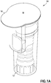
- a container generally indicated as 10, is shown in accordance with one aspect of the invention.
- the container 10 is generally configured as a vessel capable of receiving and housing a medical connector, generally indicated as 12, which can be used as part of a CSTD.
- the connector 12 is desirably disposed entirely within an interior cavity 14 (shown in FIG. 1B ) of the container 10.
- the container 10 and the connector 12 have correspondingly shaped features to facilitate the insertion and removal of the connector 12 into and from the container 10, as will be described in greater detail hereinafter.
- a cap 16 (shown in FIG. 1A ) is provided to enclose the interior cavity 14 of the container 10.
- the cap 16 may be in the form of a membrane that provides a seal with the container to prevent contaminants from entering the interior cavity 14.
- the cap 16 is removable from the container 10 such that the interior cavity 14 may be accessed once the cap 16 is removed.
- the cap 16 and the container 10 may be separate components or formed together as a combined structure.
- a security feature (not shown) may be provided on the cap 16 or the container 10 to indicate an attempt to remove the cap 16 and access the interior cavity 14.
- the cap 16, once removed can be replaced on the container 10 to reclose the interior cavity 14.
- the cap 16 may be connected to the container 10 by a connection element (not shown).
- the cap 16 has a tab 18 configured for being gripped by a user's fingers to facilitate removal of the cap 16.
- the container 10 is a generally tubular body having a sidewall 20 defining an open top end 22 and a closed bottom end 24.
- the sidewall 20 extends continuously between the open top end 22 and the closed bottom end 24 along a central axis 26 to define the interior cavity 14.
- the sidewall 20 may be inclined relative to the central axis 26 such that the container 10 has a substantially conical shape that narrows radially inward from the open top end 22 to the closed bottom end 24.
- the sidewall is substantially parallel relative to the central axis 26 such that the container 10 has a substantially cylindrical shape.
- the container 10 is sealed at the top end 22 by the cap 16.
- a lip 28 extends radially outward from the open top end 22 relative to the central axis 26.
- the lip 28 provides an interface for the engagement of the cap 16 with the container 10.
- the closed bottom end 24 may have a substantially flattened shape to enable the container 10 to be supported when the closed bottom end 24 is placed on a level surface.
- the closed bottom end 24 may have a rounded or arcuate shape, or a shape configured to correspond to a bottom end of the connector 12.
- the container 10 may be constructed from any known material, such as a molded, injected, or thermo-formed plastic material.
- the container 10 is constructed from a material that provides flexibility of the sidewall 20 in at least the radial direction with respect to the central axis 26.
- the container 10 is desirably constructed from a material that allows the cross-sectional shape of the container 10 to change with an application of a radially-directed force, as will be described in greater detail hereinafter.
- the container 10 has a pair of tabs 30 on an outer portion of the sidewall 20.
- the tabs 30 extend radially outward from the sidewall 20 relative to the central axis 26.
- each tab 30 may be in the form of a substantially cylindrical projection that extends radially outward in a direction substantially perpendicular to the central axis 26.
- the tabs 30 may be oriented 180 degrees apart around a circumference of the container 10. As will be described hereinafter, the tabs 30 define a gripping surface by which the container 10 may be gripped.
- the container 10 is configured to deflect radially inward in response to a radially-directed force imparted on the tabs 30.
- the tabs 30 may be hollow, such that the sidewall 20 has a uniform thickness throughout the longitudinal length of the container 10.
- the tabs 30 may be solid, such that the sidewall 20 has an increased thickness in the region of the tabs 30.
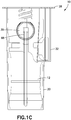
- the container 10 further includes a recess 32 that is configured for receiving an activation tab of the connector 12, as will be described hereinafter.
- the recess 32 extends radially outward relative to the central axis 26.
- the recess 32 also extends along at least a portion of the longitudinal length of the container 10.
- the recess 32 is shaped such that the sidewall 20 bulges radially outward in the area of the recess 32.
- the recess 32 also orients the connector 12 such that it can be received in the interior cavity 14 in one direction only. In this manner, the connector 12 is aligned with the tabs 30 and the recess 32.
- Other features of the container 10 or the connector 12 may be used to align the connector 12 within the interior cavity 14 of the container 10.
- a pair of longitudinal protrusions 34 extend radially inward from the sidewall 20 inside the interior cavity 14.
- the protrusions 34 extend in a direction substantially parallel to the central axis 26.
- the protrusions 34 may be angled relative to the central axis 26.
- the protrusions 34 may have any desired shape, including, but not limited to, square, rectangular, rounded, etc.
- the protrusions 34 extend from a region of the inner sidewall 20 proximate to the closed bottom end 24 to an area of the inner sidewall 20 opposite the tabs 30.
- the sidewall 20 tapers outward from the closed bottom end 24 to the open top end 22, such as shown in FIG.
- the protrusions 34 may have a first surface that is parallel and coextensive with the tapering sidewall 20 and a second surface that is parallel to the central axis 26 and offset, at least in part, from the sidewall 20.
- the protrusions 34 may have a first surface that is parallel and coextensive with the sidewall 20 and a second surface that is parallel and offset from the sidewall 20.
- the protrusions 34 may be oriented 180 degrees apart around a circumference of the container 10 such that each protrusion 34 is aligned with the corresponding tab 30.
- each protrusion 34 may be aligned with an axis extending through the center of each tab 30.
- the protrusions 34 define an alignment feature for aligning the connector 12 within the interior cavity 14 of the container 10.
- the protrusions 34 interact with a corresponding slot on the connector 12 to prevent a rotation of the connector 12 within the container 10.
- the protrusions 34 are configured to deflect radially inward in response to a radially-directed force imparted on the tabs 30. While FIGS.
- FIGS. 2A-2C illustrate a pair of protrusions 34 separated equally about the circumference of the container 10, it is to be appreciated that more than two protrusions 34 may be provided with equal or unequal separation about the circumference of the container 10. However, at least one protrusion 34 is provided on an inner sidewall 20 opposite a single tab 30.
- the connector 12 is an assembly of components adapted to create a tamper-proof connection interface between the connector 12 and a medical device or component, including, but not limited to, a vial, fluid bag, syringe, or patient fluid line.
- the connector 12 is configured to prevent accidental or inadvertent disconnection of the connector 12 and the medical device or component, which could compromise the integrity of the CSTD.
- the connector 12 is desirably disposed entirely within the interior cavity 14 (shown in FIG. 1B ) of the container 10.
- the container 10 and the connector 12 have correspondingly shaped features to facilitate the insertion and removal of the connector 12 into and from the container 10.
- the connector 12 has a body 36, having a distal end 38, a proximal end 40, and a generally cylindrical sidewall 42 extending between the distal end 38 and the proximal end 40 and defining a fluid passageway 44 therethrough (shown in FIG. 3A ).
- An activation tab 72 is provided on the body 36 for connecting and/or disconnecting the connector 12 from a medical device or component.
- the activation tab 72 extends radially outward from the sidewall 42.
- the activation tab 72 is shaped to be received within a recess 32 provided on the container 10, as shown in FIG. 1C .
- Other features of the connector 12 may be used to align the connector 12 within the container 10 such that the container 10 is aligned relative to the protrusions 34.
- the connector 12 includes an inner member 46 located at the proximal end 40 of the body 36.
- the inner member 46 provides a connection interface with a patient delivery device 48, such as a syringe or an IV line (shown in FIG. 3B ). It can be appreciated that depending upon the orientation of the connector 12 with respect to the patient delivery device 48, the connection interface can be considered to be located at the distal end 38 of the body 36.
- the inner member 46 is configured to cooperate with the patient delivery device 48 to provide fluid communication via the fluid passageway 44 between the connector 12 and the patient delivery device 48.
- the inner member 46 as shown in FIGS.
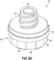
- FIGS. 3A-3D illustrate the luer-lock connector 50 as a male connector
- the luer-lock connector 50 may be embodied as a female connector configured for connecting to a male connector on the corresponding luer connection 52 on the patient delivery device 48.
- the luer-lock connector 50 can be embodied as any other mating connection configured for coupling with the patient delivery device 48.
- an outer member 54 surrounds at least a portion of the inner member 46.
- a radial extension 56 of the inner member 46 is received within an annular sleeve 58 on the outer member 54 such that the inner member 46 is configured to rotate freely with respect to the outer member 54 and with respect to the patient delivery device 48.
- the freely rotating state prevents inadvertent and/or accidental disconnection of the patient delivery device 48 from the inner member 46, as the application of rotational force to the patient delivery device 48 will cause the inner member 46 to rotate with the rotation of the patient delivery device 48 without applying the rotational force necessary to remove the patient delivery device 48 from the inner member 46.
- the connector 12 of the present invention and/or the connection interface of the present invention is not limited for use with a patient delivery device 48 but can be used in association with other components in a CSTD or other medical devices.
- the inner member 46 has an annular skirt 60 extending distally from the radial extension 56.
- the annular skirt 60 is recessed relative to the radial extension 56.
- the annular skirt 60 has a locking arrangement 62 configured to prevent free rotation of the inner member 46 relative to the outer member 54 to enable connection of the inner member 46 to and/or disconnection of the inner member 46 from the patient delivery device 48.
- the locking arrangement generally indicated as 62, is configured to be engaged by the protrusions 34 of the container 10 upon the application of a compressive force F, shown in FIGS. 4A-4C .
- the inner member 46 is locked relative to the outer member 54, such that an axial or rotational force can be applied to the interface between the inner member 46 and the patient delivery device 48 to attach or detach the connector 12 from the patient delivery device 48.
- the locking arrangement 62 can include a plurality of teeth 64 extending from an outer surface of the annular skirt 60.
- the teeth 64 are spaced radially about the circumference of the annular skirt 60 at equal intervals.
- the teeth 64 may be spaced with unequal intervals about the circumference of the annular skirt 60.
- the teeth 64 are configured to clear the inner surface of the outer member 54 during rotation of the inner member 46 relative to the outer member 54.
- the teeth 64 are separated by a plurality of engagement surfaces 66 extending therebetween.
- the teeth 64 are generally concealed by the outer member 54 of the body 36.
- a single tooth 64 may be provided on the annular skirt 60.
- the engagement surface 66 may provide a frictional interface with the inner member 46 to prevent the rotation of the inner member 46.
- the surface finish, coating, and material of the engagement surface 66 and the inner member 46 may be optimized for achieving the desired frictional conditions for proper functioning of the locking arrangement 62.
- the engagement surface 66 is configured to be engaged by the protrusions 34 of the container 10 upon the application of a compressive force F, shown in FIG. 5 .
- a protrusion 34 is disposed between two adjacent teeth 64 such that the inner member 46 is locked relative to the outer member 54. In this manner, an axial or rotational force can be applied to the interface between the inner member 46 and the patient delivery device 48 to attach or detach the connector 12 to or from the patient delivery device 48.
- a pair of slots 68 is provided on the outer member 54 of the body 36; however, a single slot 68 may be provided in alternative aspects.
- the slots 68 extend between the distal end 38 and the proximal end 40 over at least a portion of the longitudinal length of the body 36. At least a portion of the slots 68 extends through the sidewall 42 of the connector 12 to define a window 70 for accessing an interior portion of the connector 12.
- the window 70 defined by the slots 68 is configured to provide access to the locking arrangement 62.
- the window 70 may be provided separately from the slots 68.
- the slots 68 need not be provided.
- the slots 68 may be oriented 180 degrees apart around a circumference of the connector 12 such that each slot 68 is aligned with the corresponding tab 30 ( FIG. 1C ).
- the longitudinal midpoint of each slot 68 may be aligned with an axis extending through the center of each tab 30.
- the slots 68 define an alignment feature for aligning the connector 12 with the protrusions 34 of the container 10.
- the slots 68 are shaped to receive the protrusions 34 such that the connector 12 is guided by the protrusions 34 as the connector 12 is inserted in or removed from the container 10. In an uncompressed state of the container 10, the protrusions 34 are not biased against the locking arrangement 62. While FIG.
- 3C illustrates a pair of slots 68 separated equally about the circumference of the connector 12, it is to be appreciated that more than two slots 68 may be provided with equal or unequal separation about the circumference of the connector 12. However, at least one slot 68 is provided in alignment with at least one of the protrusions 34 and the tabs 30 when the connector 12 is inserted in the container 10. In various aspects, the number of slots 68 need not correspond to the number of protrusions 34.
- the application of the compressive force F in a radial direction causes the container to be compressed radially in a direction of the force F.
- the container 10 is locally compressed such that the portions of the sidewall 20 proximate to the tabs 30 are compressed towards each other.
- the protrusions 34 are also biased toward one another such that the distance between the opposing protrusions 34 is reduced when the compressive force F is applied to the tabs 30.
- the compressive force F causes the protrusion 34 to be biased toward an inner sidewall of the container 10 opposite the protrusion 34 such that the distance between the protrusion 34 and the opposing sidewall is reduced when the compressive force F is applied to the tabs 30.
- the structure of the container 10 of the present invention is such that it requires the deliberate action of applying a radially-directed compressive force F on the tabs 30 to cause the protrusions 34 to be biased against the locking arrangement 62 in order to prevent rotational movement of the inner member 46 relative to the outer member 54, and thereby permit tightening or loosening of the patient delivery device 48 by the application of a rotational force thereto.
- the protrusions 34 engage the locking arrangement 62 by extending through the window 70 of the slots 68. In this manner, the protrusions 34 engage the annular skirt 60 of the inner member 46. In particular, the protrusions 34 engage the engagement surface 66 of the annular skirt 60 in a region between the teeth 64.
- a frictional interface between the protrusions 34 and the engagement surface 66 may be created as a result of an application of a radially-directed compressive force F on the tabs 30.
- the protrusions 34 are biased against the engagement surface 66 to prevent the rotation of the inner member 46 relative to the outer member 54.
- Engagement of the locking arrangement 62 by the protrusions 34 causes the inner member 46 to be locked relative to the outer member 54, such that an axial or rotational force can be applied to the interface between the inner member 46 and the patient delivery device 48 to attach or detach the connector 12 to or from the patient delivery device 48.
- the container 10 By releasing the force F, the container 10 reverts to its original shape, where the relative distance between the protrusions 34 is increased such that the protrusions 34 are disengaged from the locking arrangement 62 and the inner member 46 can rotate freely relative to the outer member 54, thereby preventing inadvertent or accidental removal of the patient delivery device 48 from the inner member 46.
- the method includes providing the container 10 and the connector 12, as described hereinabove. Desirably, the connector 12 is disposed entirely within the container 10 and sealed by the cap 16. After removing the cap 16, a radially-directed compressive force F is applied to the tabs 30 of the container 10, thereby causing compression of the container 10 and biasing of the protrusions 34 of the container 10 toward one another. The method further includes the engagement of the protrusions 34 with the locking arrangement 62 due to the radial deflection of the protrusions 34.
- the protrusions 34 are deflected radially, the protrusions 34 are advanced through the window 70 and biased into engagement with the engagement surface 66 of the locking arrangement 62. Such engagement prevents free rotation of the inner member 46 relative to the outer member 54, thereby allowing the connection between the patient delivery device 48 and the inner member 46 of the connector 12.
- the protrusions 34 prevent rotation of the connector 12 within the container 10 while the patient delivery device 48 is secured to the inner member 46, any other portion of the connector 12 may interface with the container 10 to prevent relative rotation between the container 10 and the connector 12.
- the activation tab 72 of the connector 12 is received within the recess 32 of the container 10, which acts to prevent relative rotation between the container 10 and the connector 12 when the connector 12 is positioned within the container 10.
- the protrusions 34 of the container 10 are disengaged from the locking arrangement 62 to permit free rotation of the inner member 46 relative to the outer member 54, thereby preventing inadvertent and/or accidental disconnection of the inner member 46 from the patient delivery device 48.
- the method can also include the re-application of the compressive force F to cause the locking arrangement 62 to be re-engaged for removal of the patient delivery device 48 from the connector 12.
- connection device 80 is shown in use with the connector 12 described hereinabove.
- the connection device 80 is configured for engaging the locking arrangement 62 on the connector 12 to prevent relative movement between the inner member 46 and the outer member 54.
- the connection device 80 has a substantially arcuate shape configured for enveloping a portion of the connector 12.
- the connection device 80 envelops a portion of the circumference of the outer member 54.
- the connection device 80 has a flexible body 82 with a pair of tabs 84 located at opposing ends of the body 82.
- the connection device 80 may have a single tab 84 located at one end of the connection device 80.
- An outer portion of the tabs 84 has a finger engagement surface 86 configured for engagement with the user's fingers.
- An inner portion of the tabs 84 has a projection 88 configured for engagement with the locking arrangement 62.
- the projection 88 extends outward from the surface of the inner portion of the tabs 84.
- the tabs 84 are connected together by a flexible joint 90 (shown in FIG. 6C ) configured to deflect with the movement of the tabs 84 toward or away from each other.
- connection device 80 of the present invention requires the deliberate action of applying a radially-directed compressive force F on the tabs 84 to cause the projections 88 to be biased against the locking arrangement 62 in order to prevent rotational movement of the inner member 46 relative to the outer member 54, and thereby permit tightening or loosening of the patient delivery device 48 (shown in FIG. 3B ) by the application of a rotational force thereto. In this manner, the patient delivery device 48 can be connected to or removed from the inner member 46 without the need for the container 10 described hereinabove with reference to FIGS. 1A-2C .
- the projection 88 of each tab 84 is configured for being received within the window 70 of the slot 68.
- the tabs 84 can be squeezed toward each other by applying a radially-directed compressive force F.
- Such force F causes the projections 88 to engage the engagement surface 66 of the locking arrangement 62.
- the projections 88 engage the engagement surface 66 of the annular skirt 60 in a region between the teeth 64.
- a frictional interface between the projections 88 and the engagement surface 66 may be created as a result of an application of a radially-directed compressive force F on the tabs 84.
- the projections 88 are biased against the engagement surface 66 to prevent the rotation of the inner member 46 relative to the outer member 54. Engagement of the locking arrangement 62 by the projections 88 causes the inner member 46 to be locked relative to the outer member 54, such that an axial or rotational force can be applied to the interface between the inner member 46 and the patient delivery device 48 to attach or detach the connector 12 to or from the patient delivery device 48.
- connection device 80 By releasing the force F, the connection device 80 reverts to its original shape, where the relative distance between the tabs 84 is increased such that the projections 88 are disengaged from the locking arrangement 62 and the inner member 46 can rotate freely relative to the outer member 54, thereby preventing inadvertent or accidental removal of the patient delivery device 48 from the inner member 46.
- connection device 80 may be naturally biased to interface with the locking arrangement 62 without requiring the application of a radially-directed force F.
- connection device 80 may be snap-fitted or clipped to the connector 12 such that the projections 88 are biased against the engagement surface 66 to prevent the rotation of the inner member 46 relative to the outer member 54.
- the connection device 80 is disengaged by unsnapping or unclipping the projections 88 with an application of a force directed in a radially-outward direction.
- the connection device 80 may be completely removable from the connector 12, or it may be formed integrally therewith such that the projections 88 can be disengaged from the engagement surface 66.
Landscapes
- Health & Medical Sciences (AREA)
- General Health & Medical Sciences (AREA)
- Pharmacology & Pharmacy (AREA)
- Life Sciences & Earth Sciences (AREA)
- Animal Behavior & Ethology (AREA)
- Public Health (AREA)
- Veterinary Medicine (AREA)
- Fluid Mechanics (AREA)
- Physics & Mathematics (AREA)
- Infusion, Injection, And Reservoir Apparatuses (AREA)
- Medical Preparation Storing Or Oral Administration Devices (AREA)
- Absorbent Articles And Supports Therefor (AREA)
- Auxiliary Devices For And Details Of Packaging Control (AREA)
Claims (11)
- Fluidtransfersystem, das aufweist:einen Behälter (10) mit:einem Behälterkörper mit einer Seitenwand (20), die sich zwischen einem offenen oberen Ende (22) und einem unteren Ende (24) entlang einer Mittelachse (26) erstreckt und einen Innenhohlraum (14) definiert; undmindestens einem Vorsprung (34), der mit der Mittelachse (26) ausgerichtet ist und sich von einem Innenabschnitt der Seitenwand (20) in den Innenhohlraum (14) erstreckt; undeinem Konnektor (12), der derart ausgestaltet ist, dass er in dem Innenhohlraum (14) aufgenommen ist, wobei der Konnektor (12) aufweist:einen Körper (36) mit einem distalen Ende (38), einem proximalen Ende (40) und einer Seitenwand (42), die sich zwischen dem distalen Ende (38) und dem proximalen Ende (40) erstreckt und zwischen diesen einen Fluiddurchgang (44) definiert;ein Innenelement (46), das an einem aus dem distalen Ende (38) und dem proximalen Ende (40) des Körpers (36) vorgesehen ist;ein Außenelement (54), das mindestens einen Abschnitt des Innenelements (46) umgibt, wobei das Innenelement (46) derart ausgestaltet ist, dass es sich relativ zu dem Außenelement (54) frei dreht; undeine Verriegelungsanordnung (62), die an mindestens einem Abschnitt des Innenelements (46) vorgesehen ist,wobei die Verriegelungsanordnung (62) derart ausgestaltet ist, dass sie mit dem mindestens einen Vorsprung (34) zusammenwirkt, um eine Drehung des Innenelements (46) relativ zu dem Außenelement (54) zu verhindern,dadurch gekennzeichnet, dass die Verriegelungsanordnung (62) durch mindestens einen Abschnitt des Außenelements (54) zugänglich ist.
- Fluidtransfersystem nach Anspruch 1, wobei die Verriegelungsanordnung (62) derart ausgestaltet ist, dass sie mit dem mindestens einen Vorsprung (34) zusammengreift, um eine Drehung des Innenelements (46) relativ zu dem Außenelement (54) beim Aufbringen einer Druckkraft (F) auf den Behälter (10) zu verhindern.
- Fluidtransfersystem nach Anspruch 1, wobei der mindestens eine Vorsprung (34) ein Paar von Vorsprüngen ist, die entgegengesetzt zueinander um einen Umfangsbereich des Behälters (10) orientiert sind.
- Fluidtransfersystem nach Anspruch 1, wobei der Behälter (10) ferner mindestens eine Lasche (30) aufweist, die sich radial nach außen von einem Außenabschnitt der Seitenwand (20) entgegengesetzt zu dem mindestens einen Vorsprung (34) erstreckt, und
wobei der mindestens eine Vorsprung vorzugsweise derart ausgestaltet ist, dass er radial nach innen ablenkt als Reaktion auf eine auf die mindestens eine Lasche (30) gerichtete Druckkraft (F). - Fluidtransfersystem nach Anspruch 1, wobei die Seitenwand (20) des Behälters (10) relativ zu der Mittelachse (26) geneigt ist, so dass sich die Seitenwand (20) radial nach innen von dem offenen oberen Ende (22) zu dem unteren Ende (24) verengt.
- Fluidtransfersystem nach Anspruch 5, wobei der mindestens eine Vorsprung (34) im Wesentlichen parallel zu der Mittelachse (26) des Behälters (10) ist.
- Fluidtransfersystem nach Anspruch 1, wobei der Konnektor (12) ferner mindestens ein Fenster (70) aufweist, das in dem Körper (36) des Konnektors (12) in einer Längsrichtung des Konnektors (12) vertieft ist.
- Fluidtransfersystem nach Anspruch 7, wobei das mindestens eine Fenster (70) derart ausgestaltet ist, dass es den mindestens einen Vorsprung (34) des Behälters (10) aufnimmt, wenn der Konnektor (12) in den Innenhohlraum (14) eingesetzt ist, um eine Drehung des Konnektors (12) relativ zu dem Behälter (10) zu verhindern.
- Fluidtransfersystem nach Anspruch 8, wobei sich das mindestens eine Fenster (70) durch die Seitenwand (42) des Konnektors (12) hindurch erstreckt, so dass beim Ablenken durch eine Druckkraft (F) der mindestens eine Vorsprung (34) mit der Verriegelungsanordnung (62) zusammengreift, um eine Drehung des Innenelements (46) relativ zu dem Außenelement (54) des Konnektors (12) zu verhindern.
- Fluidtransfersystem nach Anspruch 1, wobei die Verriegelungsanordnung (62) mindestens einen Zahn (64) aufweist, der sich von einer Eingriffsfläche (66) der Verriegelungsanordnung (62) erstreckt,
wobei die Eingriffsfläche (66) der Verriegelungsanordnung (62) beim Aufbringen einer Druckkraft (F) mit dem mindestens einen Vorsprung (34) zusammengreift. - Fluidtransfersystem nach Anspruch 1, wobei das Innenelement (46) eine Luer-Lock-Verbindung (50) aufweist.
Applications Claiming Priority (2)
| Application Number | Priority Date | Filing Date | Title |
|---|---|---|---|
| US201461982049P | 2014-04-21 | 2014-04-21 | |
| PCT/US2015/026934 WO2015164416A1 (en) | 2014-04-21 | 2015-04-21 | Fluid transfer device and packaging therefor |
Publications (2)
| Publication Number | Publication Date |
|---|---|
| EP3134059A1 EP3134059A1 (de) | 2017-03-01 |
| EP3134059B1 true EP3134059B1 (de) | 2020-03-04 |
Family
ID=53059451
Family Applications (1)
| Application Number | Title | Priority Date | Filing Date |
|---|---|---|---|
| EP15721426.3A Active EP3134059B1 (de) | 2014-04-21 | 2015-04-21 | Fluidtransfervorrichtung und verpackung dafür |
Country Status (8)
| Country | Link |
|---|---|
| US (3) | US9999570B2 (de) |
| EP (1) | EP3134059B1 (de) |
| JP (2) | JP6449910B2 (de) |
| CN (2) | CN106413661B (de) |
| CA (1) | CA2946566C (de) |
| ES (1) | ES2792512T3 (de) |
| IL (2) | IL273763B2 (de) |
| WO (1) | WO2015164416A1 (de) |
Families Citing this family (17)
| Publication number | Priority date | Publication date | Assignee | Title |
|---|---|---|---|---|
| AU2015252808B2 (en) | 2014-05-02 | 2019-02-21 | Excelsior Medical Corporation | Strip package for antiseptic cap |
| WO2016182822A1 (en) | 2015-05-08 | 2016-11-17 | Icu Medical, Inc. | Medical connectors configured to receive emitters of therapeutic agents |
| EP4194043A1 (de) | 2016-10-14 | 2023-06-14 | ICU Medical, Inc. | Desinfektionskappen fur medizinische konnektoren |
| US11103651B2 (en) | 2016-12-13 | 2021-08-31 | Beckon, Dickinson and Company | Safety needle devices |
| US10729843B2 (en) | 2016-12-12 | 2020-08-04 | Becton, Dickinson And Company | Dual packaging for fill needle and safety needle |
| US11173253B2 (en) | 2016-12-12 | 2021-11-16 | Becton, Dickinson And Company | Packaging for safety needle |
| US10792438B2 (en) | 2016-12-13 | 2020-10-06 | Becton, Dickinson And Company | Safety needle devices |
| US11147910B2 (en) * | 2016-12-12 | 2021-10-19 | Becton, Dickinson And Company | Packaging for safety needle |
| US10589036B2 (en) | 2016-12-13 | 2020-03-17 | Becton, Dickinson And Company | Safety needle device |
| WO2018204206A2 (en) | 2017-05-01 | 2018-11-08 | Icu Medical, Inc. | Medical fluid connectors and methods for providing additives in medical fluid lines |
| WO2018224644A1 (en) | 2017-06-08 | 2018-12-13 | Novartis Ag | Injection device and injection solution transferring system |
| CA3114876C (en) | 2018-10-03 | 2026-04-07 | Takeda Pharmaceutical Company Limited | Packaging for multiple containers |
| BR112021006411A2 (pt) | 2018-10-03 | 2021-07-06 | Takeda Pharmaceuticals Co | dispositivo de agrupamento para um único ou múltiplos recipientes médicos |
| USD1091814S1 (en) * | 2022-08-01 | 2025-09-02 | Equashield Medical Ltd. | Adaptor |
| US20240269452A1 (en) * | 2022-11-17 | 2024-08-15 | Icu Medical, Inc. | Medical connectors |
| USD1105422S1 (en) | 2024-02-09 | 2025-12-09 | Icu Medical, Inc. | Medical connector cover |
| PL249120B1 (pl) * | 2024-03-21 | 2026-03-02 | Pomorski Univ Medyczny W Szczecinie | Nakrętka na butelkę do bezpiecznego i kontrolowanego pobierania płynnych preparatów medycznych w pozycji stojącej |
Family Cites Families (150)
| Publication number | Priority date | Publication date | Assignee | Title |
|---|---|---|---|---|
| US4436125A (en) | 1982-03-17 | 1984-03-13 | Colder Products Company | Quick connect coupling |
| SE434700B (sv) | 1983-05-20 | 1984-08-13 | Bengt Gustavsson | Anordning for lufttet overforing av substans fran ett kerl till ett annat |
| WO1984004673A1 (en) | 1983-05-20 | 1984-12-06 | Bengt Gustavsson | A device for transferring a substance |
| ATE66806T1 (de) | 1986-11-06 | 1991-09-15 | Bengt Gustavsson | Behaelter fuer lagerung oder sammlung von fluessigkeiten und trockenen substanzen. |
| US5334188A (en) | 1987-12-07 | 1994-08-02 | Nissho Corporation | Connector with injection site |
| US5052725A (en) | 1989-03-13 | 1991-10-01 | Colder Products Company | Two piece molded female coupling |
| US5104158A (en) | 1989-03-13 | 1992-04-14 | Colder Products Company | Two piece molded female coupling |
| US5122129A (en) | 1990-05-09 | 1992-06-16 | Olson Donald J | Sampler coupler device useful in the medical arts |
| DE9105229U1 (de) | 1991-04-27 | 1991-06-13 | B. Braun Melsungen Ag, 3508 Melsungen | Ventilvorrichtung für einen Katheter |
| PT681493E (pt) | 1991-12-18 | 2000-12-29 | Icu Medical Inc | Valvula medica |
| SE9203659L (sv) | 1992-12-04 | 1994-02-14 | Dicamed Ab | Ventilanordning för aseptisk injicering och uttag av medicinsk vätska i/ur behållare samt dess användning |
| US5478328A (en) | 1992-05-22 | 1995-12-26 | Silverman; David G. | Methods of minimizing disease transmission by used hypodermic needles, and hypodermic needles adapted for carrying out the method |
| GB9211912D0 (en) | 1992-06-04 | 1992-07-15 | Drg Flexpak Ltd | Vial connector system |
| US5290254A (en) | 1992-11-16 | 1994-03-01 | Vaillancourt Vincent L | Shielded cannula assembly |
| US5509911A (en) | 1992-11-27 | 1996-04-23 | Maxxim Medical, Inc. | Rotating adapter for a catheterization system |
| WO1994023775A1 (en) | 1993-03-23 | 1994-10-27 | Abbott Laboratories | Securing collar for cannula connector |
| US5280876A (en) | 1993-03-25 | 1994-01-25 | Roger Atkins | Limited restriction quick disconnect valve |
| US5395348A (en) | 1993-05-04 | 1995-03-07 | Symbiosis Corporation | Medical intravenous administration line connectors |
| US5360011A (en) | 1993-07-13 | 1994-11-01 | Mccallister Teresa D | Blood sample collection |
| US5472430A (en) | 1993-08-18 | 1995-12-05 | Vlv Associates | Protected needle assembly |
| US5609584A (en) | 1994-05-18 | 1997-03-11 | Gettig Technologies, Inc. | Adaptor system for use with a syringe |
| US5487728A (en) | 1994-05-19 | 1996-01-30 | Vaillancourt; Vincent L. | Connector assembly |
| JPH10504736A (ja) | 1994-06-24 | 1998-05-12 | アイシーユー メディカル、インコーポレイティッド | 流体移送デバイス及び使用方法 |
| US5545152A (en) | 1994-10-28 | 1996-08-13 | Minimed Inc. | Quick-connect coupling for a medication infusion system |
| US5607392A (en) | 1995-01-13 | 1997-03-04 | Ryder International Corporation | Fixed needle connector for IV assembly and method of assembling |
| US5647845A (en) | 1995-02-01 | 1997-07-15 | Habley Medical Technology Corporation | Generic intravenous infusion system |
| IL114960A0 (en) | 1995-03-20 | 1995-12-08 | Medimop Medical Projects Ltd | Flow control device |
| SE509950C2 (sv) | 1995-05-02 | 1999-03-29 | Carmel Pharma Ab | Anordning för administrering av toxisk vätska |
| US5700248A (en) | 1995-12-15 | 1997-12-23 | Icu Medical, Inc. | Medical valve with tire seal |
| US5807347A (en) | 1995-12-21 | 1998-09-15 | Bonaldo; Jean M. | Medical valve element |
| US5897526A (en) | 1996-06-26 | 1999-04-27 | Vaillancourt; Vincent L. | Closed system medication administering system |
| US6221056B1 (en) | 1996-12-20 | 2001-04-24 | David G. Silverman | Strong diaphragm/safe needle units and components for transfer of fluids |
| US6089541A (en) | 1998-09-10 | 2000-07-18 | Halkey-Roberts Corporation | Valve having a valve body and a deformable stem therein |
| IT236233Y1 (it) | 1997-11-26 | 2000-08-08 | Eurospital S P A | Dispositivo per il collegamento di un contenitore di prodottofarmaceutico ad una sacca di prodotto liquido per effettuare il |
| US6019750A (en) | 1997-12-04 | 2000-02-01 | Baxter International Inc. | Sliding reconstitution device with seal |
| US6378714B1 (en) * | 1998-04-20 | 2002-04-30 | Becton Dickinson And Company | Transferset for vials and other medical containers |
| DE19828651C2 (de) | 1998-06-26 | 2000-07-13 | Fresenius Medical Care De Gmbh | Konnektorelement mit Verschlußteil für die Medizintechnik |
| US6358236B1 (en) | 1998-08-06 | 2002-03-19 | Baxter International Inc. | Device for reconstituting medicaments for injection |
| AR021220A1 (es) | 1998-09-15 | 2002-07-03 | Baxter Int | DISPOSITIVO DE CONEXIoN PARA ESTABLECER UNA COMUNICACIoN FLUíDA ENTRE UN PRIMER RECIPIENTE Y UN SEGUNDO RECIPIENTE. |
| US6113583A (en) | 1998-09-15 | 2000-09-05 | Baxter International Inc. | Vial connecting device for a sliding reconstitution device for a diluent container |
| US20020173748A1 (en) | 1998-10-29 | 2002-11-21 | Mcconnell Susan | Reservoir connector |
| DE69928827T2 (de) | 1998-10-29 | 2006-08-31 | Medtronic MiniMed, Inc., Northridge | Reservoiranschluss |
| FR2789369B1 (fr) | 1999-02-10 | 2001-04-27 | Biodome | Dispositif de connexion entre un recipient et un contenant et ensemble pret a l'emploi comprenant un tel dispositif |
| US6139534A (en) | 2000-01-24 | 2000-10-31 | Bracco Diagnostics, Inc. | Vial access adapter |
| US6832994B2 (en) | 2000-01-24 | 2004-12-21 | Bracco Diagnostics Inc. | Table top drug dispensing vial access adapter |
| US6544246B1 (en) | 2000-01-24 | 2003-04-08 | Bracco Diagnostics, Inc. | Vial access adapter and vial combination |
| SE0001278L (sv) | 2000-04-06 | 2001-10-08 | Peter Unger Med P U Med Konsul | Sterilkoppling |
| JP4372310B2 (ja) | 2000-04-10 | 2009-11-25 | ニプロ株式会社 | 混注用アダプター |
| US6343629B1 (en) | 2000-06-02 | 2002-02-05 | Carmel Pharma Ab | Coupling device for coupling a vial connector to a drug vial |
| US6629958B1 (en) | 2000-06-07 | 2003-10-07 | Ronald P. Spinello | Leak sealing needle |
| SE517084C2 (sv) | 2000-08-10 | 2002-04-09 | Carmel Pharma Ab | Förfarande och anordningar vid aseptisk beredning |
| FR2819174B1 (fr) | 2001-01-08 | 2003-06-13 | Pierre Frezza | Ampoule pour le conditionnement et le transfert d'un liquide ou d'une poudre a usage medical dans un contenant |
| US6474375B2 (en) | 2001-02-02 | 2002-11-05 | Baxter International Inc. | Reconstitution device and method of use |
| US6656433B2 (en) | 2001-03-07 | 2003-12-02 | Churchill Medical Systems, Inc. | Vial access device for use with various size drug vials |
| US7004934B2 (en) | 2001-09-06 | 2006-02-28 | Vaillancourt Vincent L | Closed system connector assembly |
| US6715520B2 (en) | 2001-10-11 | 2004-04-06 | Carmel Pharma Ab | Method and assembly for fluid transfer |
| US6911025B2 (en) | 2002-01-25 | 2005-06-28 | Jms Co., Ltd. | Connector system for sterile connection |
| JP3972665B2 (ja) | 2002-01-25 | 2007-09-05 | 株式会社ジェイ・エム・エス | 無菌接続コネクタシステム |
| US6875205B2 (en) | 2002-02-08 | 2005-04-05 | Alaris Medical Systems, Inc. | Vial adapter having a needle-free valve for use with vial closures of different sizes |
| US7744581B2 (en) | 2002-04-08 | 2010-06-29 | Carmel Pharma Ab | Device and method for mixing medical fluids |
| US7867215B2 (en) | 2002-04-17 | 2011-01-11 | Carmel Pharma Ab | Method and device for fluid transfer in an infusion system |
| US7350535B2 (en) | 2002-04-26 | 2008-04-01 | Gl Tool And Manufacturing Co. Inc. | Valve |
| WO2003090843A1 (en) | 2002-04-26 | 2003-11-06 | Millipore Corporation | Disposable, sterile fluid transfer device |
| SE523001C2 (sv) | 2002-07-09 | 2004-03-23 | Carmel Pharma Ab | En kopplingsdel, en koppling, en infusionspåse, en infusionsanordning och ett förfarande för överföring av medicinska substanser |
| EP1560622B1 (de) | 2002-07-09 | 2008-03-05 | Carmel Pharma AB | Vorrichtung zur injektion von medizinischen substanzen |
| US7040598B2 (en) | 2003-05-14 | 2006-05-09 | Cardinal Health 303, Inc. | Self-sealing male connector |
| US20040249235A1 (en) | 2003-06-03 | 2004-12-09 | Connell Edward G. | Hazardous material handling system and method |
| GB0317175D0 (en) | 2003-07-23 | 2003-08-27 | Liversidge Barry P | Medical needle system |
| KR100940701B1 (ko) | 2003-07-31 | 2010-02-08 | 가부시끼가이샤 제이엠에스 | 의료용 커넥터 시스템 |
| US7390321B2 (en) | 2003-09-18 | 2008-06-24 | Advanced Technology Materials, Inc. | Connection having laminar flow for the delivery of a substance |
| PT2463201E (pt) | 2003-10-30 | 2014-05-09 | Teva Medical Ltd | Dispositivo para manuseamento de fármacos de segurança |
| US20080287914A1 (en) | 2003-12-22 | 2008-11-20 | Philip Wyatt | Medicament administration apparatus |
| US7530546B2 (en) | 2004-01-13 | 2009-05-12 | Rymed Technologies, Inc. | Swabbable needle-free injection port valve system with zero fluid displacement |
| IL161660A0 (en) * | 2004-04-29 | 2004-09-27 | Medimop Medical Projects Ltd | Liquid drug delivery device |
| EP1787667A4 (de) | 2004-08-04 | 2010-07-07 | Ajinomoto Kk | Kommunizierende nadel für die kommunikation von zwei oder mehr behältern |
| US7731678B2 (en) | 2004-10-13 | 2010-06-08 | Hyprotek, Inc. | Syringe devices and methods for mixing and administering medication |
| US20060089593A1 (en) | 2004-10-26 | 2006-04-27 | Sergio Landau | Needle-free injection device for individual users |
| US20060161115A1 (en) | 2004-11-05 | 2006-07-20 | Fangrow Thomas F | Soft-grip medical connector |
| WO2006058435A2 (en) * | 2004-12-03 | 2006-06-08 | Duoject Medical Systems Inc. | Cartridge, device and method for pharmaceutical storage, mixing and delivery |
| WO2006128500A1 (en) | 2004-12-23 | 2006-12-07 | Bracco Research Sa | Liquid transfer device for medical dispensing containers |
| JP4647365B2 (ja) | 2005-03-31 | 2011-03-09 | 日本シャーウッド株式会社 | 医療用の接続器具 |
| WO2006124756A2 (en) | 2005-05-13 | 2006-11-23 | Bob Rogers | Medical substance transfer system |
| US7803140B2 (en) | 2005-07-06 | 2010-09-28 | Icu Medical, Inc. | Medical connector with closeable male luer |
| CN101437463B (zh) | 2005-11-07 | 2012-12-05 | 伯尔拉工业有限公司 | 通气的安全处理小瓶配接器 |
| EP1797919A1 (de) | 2005-12-16 | 2007-06-20 | Bracco Research S.A. | Vorrichtung zum Übertragen von Flüssigkeiten für Behälter zur Abgabe von Medikamenten |
| AT503142B1 (de) | 2006-01-18 | 2009-05-15 | Friedrich Ing Pipelka | Behälter zur einbringung zumindest eines unsterilen gefässes in einen sterilen bereich |
| US7547300B2 (en) | 2006-04-12 | 2009-06-16 | Icu Medical, Inc. | Vial adaptor for regulating pressure |
| US8257286B2 (en) | 2006-09-21 | 2012-09-04 | Tyco Healthcare Group Lp | Safety connector apparatus |
| US7857805B2 (en) | 2006-10-02 | 2010-12-28 | B. Braun Medical Inc. | Ratcheting luer lock connector |
| US8167863B2 (en) | 2006-10-16 | 2012-05-01 | Carefusion 303, Inc. | Vented vial adapter with filter for aerosol retention |
| ES2362449T3 (es) | 2006-10-25 | 2011-07-05 | Icu Medical, Inc. | Conector médico. |
| US7900659B2 (en) | 2006-12-19 | 2011-03-08 | Carefusion 303, Inc. | Pressure equalizing device for vial access |
| US7883499B2 (en) | 2007-03-09 | 2011-02-08 | Icu Medical, Inc. | Vial adaptors and vials for regulating pressure |
| US7942860B2 (en) | 2007-03-16 | 2011-05-17 | Carmel Pharma Ab | Piercing member protection device |
| EP2606872B1 (de) | 2007-04-23 | 2014-07-02 | Equashield Medical Ltd | Verfahren und Vorrichtung zum kontaminationsfreien Transfer eines gefährlichen Arzneimittels |
| US7975733B2 (en) | 2007-05-08 | 2011-07-12 | Carmel Pharma Ab | Fluid transfer device |
| JP5179573B2 (ja) * | 2007-05-08 | 2013-04-10 | カルメル ファルマ アクチボラゲット | 流体移送装置 |
| GB2451891A (en) | 2007-08-17 | 2009-02-18 | Univ Sheffield Hallam | Medical fluid connector with features to ensure correct coupling |
| WO2009038860A2 (en) | 2007-09-18 | 2009-03-26 | Medeq Llc | Medicament mixing and injection apparatus |
| ATE526933T1 (de) | 2008-01-17 | 2011-10-15 | Teva Medical Ltd | Spritzenadapterelement in einem arznei- mischsystem |
| US8449521B2 (en) | 2008-02-06 | 2013-05-28 | Intravena, Llc | Methods for making and using a vial shielding convenience kit |
| FR2928539B1 (fr) | 2008-03-12 | 2012-02-24 | Vygon | Dispositif d'interfacage pour flacons a perforer a fins de preparations de liquides perfuses |
| JPWO2009133755A1 (ja) | 2008-05-02 | 2011-09-01 | テルモ株式会社 | コネクタ組立体 |
| WO2009133754A1 (ja) | 2008-05-02 | 2009-11-05 | テルモ株式会社 | コネクタ組立体 |
| US20100106129A1 (en) * | 2008-10-24 | 2010-04-29 | Baxter International Inc. | Controlled force mechanism for a fluid connector |
| TWI524875B (zh) * | 2008-12-30 | 2016-03-11 | 大塚製藥工場股份有限公司 | 用於施加流體的施加器裝置和系統、和設置在施加器裝置中的流體盛裝容器 |
| US8512309B2 (en) | 2009-01-15 | 2013-08-20 | Teva Medical Ltd. | Vial adapter element |
| CA2753142C (en) | 2009-02-24 | 2017-08-29 | Simplivia Healthcare Ltd. | Vial adapter assembly in drug mixing system |
| US8454579B2 (en) | 2009-03-25 | 2013-06-04 | Icu Medical, Inc. | Medical connector with automatic valves and volume regulator |
| US8317741B2 (en) | 2009-05-26 | 2012-11-27 | Kraushaar Timothy Y | Apparatus and methods for administration of reconstituted medicament |
| MX2012000100A (es) | 2009-07-01 | 2012-04-02 | Fresenius Med Care Hldg Inc | Dispositivos de suministro de farmaco y sistemas y metodos relacionados. |
| US8277424B2 (en) | 2009-07-17 | 2012-10-02 | Pan Hsiu-Feng | Needle-less syringe adapter |
| CN104873389B (zh) | 2009-07-29 | 2017-12-05 | Icu医学有限公司 | 流体传输装置及使用方法 |
| CN102686266B (zh) | 2009-09-04 | 2015-06-17 | B.布劳恩梅尔松根股份公司 | 可选择性密封阳型无针连接器及相关方法 |
| MX344382B (es) | 2009-10-23 | 2016-12-14 | Amgen Inc * | Adaptador de vial y sistema. |
| DK2332510T3 (da) | 2009-12-09 | 2013-05-13 | Hoffmann La Roche | Forbindelsesorgan |
| FR2956326A1 (fr) | 2010-02-17 | 2011-08-19 | Vygon | Ensemble de connecteurs pour un circuit liquide |
| US8834443B2 (en) | 2010-03-22 | 2014-09-16 | Alex Yeung | Injection safety system |
| JP5875974B2 (ja) | 2010-03-30 | 2016-03-02 | テルモ株式会社 | コネクタおよびコネクタ組立体 |
| US8162013B2 (en) * | 2010-05-21 | 2012-04-24 | Tobias Rosenquist | Connectors for fluid containers |
| ES2814724T3 (es) * | 2010-05-21 | 2021-03-29 | Carmel Pharma Ab | Conector, recipiente para fluido |
| NZ714715A (en) * | 2010-05-27 | 2016-11-25 | J&J Solutions Inc | Closed fluid transfer system |
| CN102958558A (zh) | 2010-06-30 | 2013-03-06 | 泰尔茂株式会社 | 连接器及连接器组装体 |
| CN103167857B (zh) | 2010-06-30 | 2014-12-10 | 泰尔茂株式会社 | 连接器及连接器组装体 |
| US20130079744A1 (en) | 2010-07-12 | 2013-03-28 | Jms Co., Ltd. | Drug solution delivery device for medical use |
| KR102253635B1 (ko) | 2010-08-25 | 2021-05-20 | 박스앨타 게엠베하 | 사용자 재구성을 용이하게 하는 어셈블리 |
| AU2011310580C1 (en) | 2010-10-01 | 2016-03-10 | Bracco Imaging Spa | Finger-grip device for medical syringe or cartridge |
| US20130303994A1 (en) | 2010-11-22 | 2013-11-14 | Novartis Ag | Adapter |
| EP2462971A1 (de) | 2010-12-13 | 2012-06-13 | Sanofi-Aventis Deutschland GmbH | Nadelanordnung für Arzneimittelverabreichungsvorrichtungen |
| US8857470B2 (en) | 2011-01-25 | 2014-10-14 | Fresenius Kabi Deutschland Gmbh | Connection device for connecting a first reservoir with a second reservoir |
| CA2827993C (en) | 2011-03-04 | 2018-04-17 | Duoject Medical Systems Inc. | Easy linking transfer system |
| US20120265163A1 (en) | 2011-04-14 | 2012-10-18 | Marc Bunjiun Cheng | Coupling system to transfer material between containers |
| FR2975896B1 (fr) | 2011-06-06 | 2014-06-06 | Biocorp Rech Et Dev | Dispositif de connexion entre un recipient et un contenant, procede d'assemblage et d'utilisation d'un tel dispositif |
| EP2545956A1 (de) * | 2011-07-15 | 2013-01-16 | Becton Dickinson France | Arzneiabgabevorrichtung und Adapter |
| JP6541349B2 (ja) | 2011-08-18 | 2019-07-10 | アイシーユー・メディカル・インコーポレーテッド | 圧力調節バイアルアダプタ |
| IL215699A0 (en) | 2011-10-11 | 2011-12-29 | Medimop Medical Projects Ltd | Liquid drug reconstitution assemblage for use with iv bag and drug vial |
| EP2773309B1 (de) | 2011-10-31 | 2016-04-20 | GE Healthcare Limited | Einstich- und füllvorrichtung |
| US9283344B2 (en) | 2012-01-03 | 2016-03-15 | Carefusion Corporation | Apparatus, system, and method of fluid delivery connection |
| ITTO20120056A1 (it) | 2012-01-24 | 2013-07-25 | Borla Ind | Connettore per linee medicali di infusione, trasfusione e simili |
| SG192311A1 (en) | 2012-02-02 | 2013-08-30 | Becton Dickinson Holdings Pte Ltd | Adaptor with injection device for coupling to a medical container |
| JP6174576B2 (ja) | 2012-05-31 | 2017-08-02 | 学校法人近畿大学 | 曝露防止用キャップ |
| EP2719420A1 (de) | 2012-10-12 | 2014-04-16 | Becton Dickinson France | Adapter für Arzneimittelabgabevorrichtung und Verfahren zur Montage des besagten Adapters daran |
| US9724269B2 (en) | 2012-11-30 | 2017-08-08 | Becton Dickinson and Company Ltd. | Connector for fluid communication |
| ES2719413T3 (es) | 2013-02-07 | 2019-07-10 | Equashield Medical Ltd | Mejoras en un sistema cerrado de transferencia de fármacos |
| IL226281A (en) | 2013-05-09 | 2017-01-31 | Kriheli Marino | Needle valve and connectors for use in fluid transfer devices |
| CN111228117B (zh) | 2014-04-21 | 2024-01-12 | 贝克顿迪金森有限公司 | 流体传送装置和用于该装置的包装件 |
| US10376654B2 (en) | 2014-04-21 | 2019-08-13 | Becton Dickinson and Company Limited | System for closed transfer of fluids and membrane arrangements for use thereof |
| CN110448461B (zh) | 2014-04-21 | 2022-07-01 | 贝克顿迪金森有限公司 | 带有断开反馈机构的注射器适配器 |
| CN106470657B (zh) | 2014-04-21 | 2020-03-17 | 贝克顿迪金森有限公司 | 用于封闭式转移流体的系统 |
| ES2901107T3 (es) | 2015-06-12 | 2022-03-21 | Becton Dickinson & Co Ltd | Adaptador de jeringa con conector giratorio |
-
2015
- 2015-04-21 US US14/691,845 patent/US9999570B2/en active Active
- 2015-04-21 EP EP15721426.3A patent/EP3134059B1/de active Active
- 2015-04-21 JP JP2016563945A patent/JP6449910B2/ja active Active
- 2015-04-21 ES ES15721426T patent/ES2792512T3/es active Active
- 2015-04-21 IL IL273763A patent/IL273763B2/en unknown
- 2015-04-21 CA CA2946566A patent/CA2946566C/en active Active
- 2015-04-21 CN CN201580028742.8A patent/CN106413661B/zh active Active
- 2015-04-21 WO PCT/US2015/026934 patent/WO2015164416A1/en not_active Ceased
- 2015-04-21 CN CN201911103477.1A patent/CN110787057B/zh active Active
-
2016
- 2016-10-20 IL IL248418A patent/IL248418B/en active IP Right Grant
-
2018
- 2018-05-17 US US15/982,114 patent/US11154457B2/en active Active
- 2018-12-06 JP JP2018229371A patent/JP6651602B2/ja active Active
-
2021
- 2021-09-23 US US17/483,404 patent/US12383466B2/en active Active
Non-Patent Citations (1)
| Title |
|---|
| None * |
Also Published As
| Publication number | Publication date |
|---|---|
| IL248418A0 (en) | 2016-11-30 |
| JP2017513615A (ja) | 2017-06-01 |
| US20220008294A1 (en) | 2022-01-13 |
| US20150297455A1 (en) | 2015-10-22 |
| JP6651602B2 (ja) | 2020-02-19 |
| ES2792512T3 (es) | 2020-11-11 |
| US12383466B2 (en) | 2025-08-12 |
| EP3134059A1 (de) | 2017-03-01 |
| WO2015164416A1 (en) | 2015-10-29 |
| JP2019034236A (ja) | 2019-03-07 |
| US11154457B2 (en) | 2021-10-26 |
| US20180263849A1 (en) | 2018-09-20 |
| CN106413661A (zh) | 2017-02-15 |
| IL273763B1 (en) | 2023-06-01 |
| IL273763B2 (en) | 2023-10-01 |
| US9999570B2 (en) | 2018-06-19 |
| CN110787057A (zh) | 2020-02-14 |
| CA2946566A1 (en) | 2015-10-29 |
| CN110787057B (zh) | 2022-06-28 |
| CN106413661B (zh) | 2019-11-29 |
| IL273763A (en) | 2020-05-31 |
| JP6449910B2 (ja) | 2019-01-09 |
| CA2946566C (en) | 2021-03-02 |
| IL248418B (en) | 2020-05-31 |
Similar Documents
| Publication | Publication Date | Title |
|---|---|---|
| US12383466B2 (en) | Fluid transfer device and packaging therefor | |
| US10850087B2 (en) | Fluid transfer device and packaging therefor | |
| US11559633B2 (en) | Syringe adapter with spinning connector | |
| AU2019255500B2 (en) | Syringe adapter with secure connection |
Legal Events
| Date | Code | Title | Description |
|---|---|---|---|
| STAA | Information on the status of an ep patent application or granted ep patent |
Free format text: STATUS: THE INTERNATIONAL PUBLICATION HAS BEEN MADE |
|
| PUAI | Public reference made under article 153(3) epc to a published international application that has entered the european phase |
Free format text: ORIGINAL CODE: 0009012 |
|
| STAA | Information on the status of an ep patent application or granted ep patent |
Free format text: STATUS: REQUEST FOR EXAMINATION WAS MADE |
|
| 17P | Request for examination filed |
Effective date: 20161117 |
|
| AK | Designated contracting states |
Kind code of ref document: A1 Designated state(s): AL AT BE BG CH CY CZ DE DK EE ES FI FR GB GR HR HU IE IS IT LI LT LU LV MC MK MT NL NO PL PT RO RS SE SI SK SM TR |
|
| AX | Request for extension of the european patent |
Extension state: BA ME |
|
| DAV | Request for validation of the european patent (deleted) | ||
| DAX | Request for extension of the european patent (deleted) | ||
| GRAP | Despatch of communication of intention to grant a patent |
Free format text: ORIGINAL CODE: EPIDOSNIGR1 |
|
| STAA | Information on the status of an ep patent application or granted ep patent |
Free format text: STATUS: GRANT OF PATENT IS INTENDED |
|
| INTG | Intention to grant announced |
Effective date: 20190919 |
|
| GRAS | Grant fee paid |
Free format text: ORIGINAL CODE: EPIDOSNIGR3 |
|
| GRAA | (expected) grant |
Free format text: ORIGINAL CODE: 0009210 |
|
| STAA | Information on the status of an ep patent application or granted ep patent |
Free format text: STATUS: THE PATENT HAS BEEN GRANTED |
|
| AK | Designated contracting states |
Kind code of ref document: B1 Designated state(s): AL AT BE BG CH CY CZ DE DK EE ES FI FR GB GR HR HU IE IS IT LI LT LU LV MC MK MT NL NO PL PT RO RS SE SI SK SM TR |
|
| REG | Reference to a national code |
Ref country code: GB Ref legal event code: FG4D |
|
| REG | Reference to a national code |
Ref country code: CH Ref legal event code: EP |
|
| REG | Reference to a national code |
Ref country code: AT Ref legal event code: REF Ref document number: 1239548 Country of ref document: AT Kind code of ref document: T Effective date: 20200315 |
|
| REG | Reference to a national code |
Ref country code: DE Ref legal event code: R096 Ref document number: 602015048132 Country of ref document: DE |
|
| REG | Reference to a national code |
Ref country code: IE Ref legal event code: FG4D |
|
| REG | Reference to a national code |
Ref country code: CH Ref legal event code: NV Representative=s name: ISLER AND PEDRAZZINI AG, CH |
|
| PG25 | Lapsed in a contracting state [announced via postgrant information from national office to epo] |
Ref country code: NO Free format text: LAPSE BECAUSE OF FAILURE TO SUBMIT A TRANSLATION OF THE DESCRIPTION OR TO PAY THE FEE WITHIN THE PRESCRIBED TIME-LIMIT Effective date: 20200604 Ref country code: FI Free format text: LAPSE BECAUSE OF FAILURE TO SUBMIT A TRANSLATION OF THE DESCRIPTION OR TO PAY THE FEE WITHIN THE PRESCRIBED TIME-LIMIT Effective date: 20200304 Ref country code: RS Free format text: LAPSE BECAUSE OF FAILURE TO SUBMIT A TRANSLATION OF THE DESCRIPTION OR TO PAY THE FEE WITHIN THE PRESCRIBED TIME-LIMIT Effective date: 20200304 |
|
| REG | Reference to a national code |
Ref country code: NL Ref legal event code: MP Effective date: 20200304 |
|
| PG25 | Lapsed in a contracting state [announced via postgrant information from national office to epo] |
Ref country code: SE Free format text: LAPSE BECAUSE OF FAILURE TO SUBMIT A TRANSLATION OF THE DESCRIPTION OR TO PAY THE FEE WITHIN THE PRESCRIBED TIME-LIMIT Effective date: 20200304 Ref country code: LV Free format text: LAPSE BECAUSE OF FAILURE TO SUBMIT A TRANSLATION OF THE DESCRIPTION OR TO PAY THE FEE WITHIN THE PRESCRIBED TIME-LIMIT Effective date: 20200304 Ref country code: HR Free format text: LAPSE BECAUSE OF FAILURE TO SUBMIT A TRANSLATION OF THE DESCRIPTION OR TO PAY THE FEE WITHIN THE PRESCRIBED TIME-LIMIT Effective date: 20200304 Ref country code: GR Free format text: LAPSE BECAUSE OF FAILURE TO SUBMIT A TRANSLATION OF THE DESCRIPTION OR TO PAY THE FEE WITHIN THE PRESCRIBED TIME-LIMIT Effective date: 20200605 Ref country code: BG Free format text: LAPSE BECAUSE OF FAILURE TO SUBMIT A TRANSLATION OF THE DESCRIPTION OR TO PAY THE FEE WITHIN THE PRESCRIBED TIME-LIMIT Effective date: 20200604 |
|
| REG | Reference to a national code |
Ref country code: LT Ref legal event code: MG4D |
|
| PG25 | Lapsed in a contracting state [announced via postgrant information from national office to epo] |
Ref country code: NL Free format text: LAPSE BECAUSE OF FAILURE TO SUBMIT A TRANSLATION OF THE DESCRIPTION OR TO PAY THE FEE WITHIN THE PRESCRIBED TIME-LIMIT Effective date: 20200304 |
|
| PG25 | Lapsed in a contracting state [announced via postgrant information from national office to epo] |
Ref country code: SK Free format text: LAPSE BECAUSE OF FAILURE TO SUBMIT A TRANSLATION OF THE DESCRIPTION OR TO PAY THE FEE WITHIN THE PRESCRIBED TIME-LIMIT Effective date: 20200304 Ref country code: SM Free format text: LAPSE BECAUSE OF FAILURE TO SUBMIT A TRANSLATION OF THE DESCRIPTION OR TO PAY THE FEE WITHIN THE PRESCRIBED TIME-LIMIT Effective date: 20200304 Ref country code: EE Free format text: LAPSE BECAUSE OF FAILURE TO SUBMIT A TRANSLATION OF THE DESCRIPTION OR TO PAY THE FEE WITHIN THE PRESCRIBED TIME-LIMIT Effective date: 20200304 Ref country code: LT Free format text: LAPSE BECAUSE OF FAILURE TO SUBMIT A TRANSLATION OF THE DESCRIPTION OR TO PAY THE FEE WITHIN THE PRESCRIBED TIME-LIMIT Effective date: 20200304 Ref country code: CZ Free format text: LAPSE BECAUSE OF FAILURE TO SUBMIT A TRANSLATION OF THE DESCRIPTION OR TO PAY THE FEE WITHIN THE PRESCRIBED TIME-LIMIT Effective date: 20200304 Ref country code: RO Free format text: LAPSE BECAUSE OF FAILURE TO SUBMIT A TRANSLATION OF THE DESCRIPTION OR TO PAY THE FEE WITHIN THE PRESCRIBED TIME-LIMIT Effective date: 20200304 Ref country code: PT Free format text: LAPSE BECAUSE OF FAILURE TO SUBMIT A TRANSLATION OF THE DESCRIPTION OR TO PAY THE FEE WITHIN THE PRESCRIBED TIME-LIMIT Effective date: 20200729 Ref country code: IS Free format text: LAPSE BECAUSE OF FAILURE TO SUBMIT A TRANSLATION OF THE DESCRIPTION OR TO PAY THE FEE WITHIN THE PRESCRIBED TIME-LIMIT Effective date: 20200704 |
|
| REG | Reference to a national code |
Ref country code: ES Ref legal event code: FG2A Ref document number: 2792512 Country of ref document: ES Kind code of ref document: T3 Effective date: 20201111 |
|
| REG | Reference to a national code |
Ref country code: AT Ref legal event code: MK05 Ref document number: 1239548 Country of ref document: AT Kind code of ref document: T Effective date: 20200304 |
|
| REG | Reference to a national code |
Ref country code: DE Ref legal event code: R097 Ref document number: 602015048132 Country of ref document: DE |
|
| PG25 | Lapsed in a contracting state [announced via postgrant information from national office to epo] |
Ref country code: MC Free format text: LAPSE BECAUSE OF FAILURE TO SUBMIT A TRANSLATION OF THE DESCRIPTION OR TO PAY THE FEE WITHIN THE PRESCRIBED TIME-LIMIT Effective date: 20200304 |
|
| PLBE | No opposition filed within time limit |
Free format text: ORIGINAL CODE: 0009261 |
|
| STAA | Information on the status of an ep patent application or granted ep patent |
Free format text: STATUS: NO OPPOSITION FILED WITHIN TIME LIMIT |
|
| PG25 | Lapsed in a contracting state [announced via postgrant information from national office to epo] |
Ref country code: AT Free format text: LAPSE BECAUSE OF FAILURE TO SUBMIT A TRANSLATION OF THE DESCRIPTION OR TO PAY THE FEE WITHIN THE PRESCRIBED TIME-LIMIT Effective date: 20200304 Ref country code: LU Free format text: LAPSE BECAUSE OF NON-PAYMENT OF DUE FEES Effective date: 20200421 Ref country code: DK Free format text: LAPSE BECAUSE OF FAILURE TO SUBMIT A TRANSLATION OF THE DESCRIPTION OR TO PAY THE FEE WITHIN THE PRESCRIBED TIME-LIMIT Effective date: 20200304 |
|
| REG | Reference to a national code |
Ref country code: BE Ref legal event code: MM Effective date: 20200430 |
|
| 26N | No opposition filed |
Effective date: 20201207 |
|
| PG25 | Lapsed in a contracting state [announced via postgrant information from national office to epo] |
Ref country code: BE Free format text: LAPSE BECAUSE OF NON-PAYMENT OF DUE FEES Effective date: 20200430 Ref country code: PL Free format text: LAPSE BECAUSE OF FAILURE TO SUBMIT A TRANSLATION OF THE DESCRIPTION OR TO PAY THE FEE WITHIN THE PRESCRIBED TIME-LIMIT Effective date: 20200304 Ref country code: SI Free format text: LAPSE BECAUSE OF FAILURE TO SUBMIT A TRANSLATION OF THE DESCRIPTION OR TO PAY THE FEE WITHIN THE PRESCRIBED TIME-LIMIT Effective date: 20200304 |
|
| PG25 | Lapsed in a contracting state [announced via postgrant information from national office to epo] |
Ref country code: IE Free format text: LAPSE BECAUSE OF NON-PAYMENT OF DUE FEES Effective date: 20200421 |
|
| PG25 | Lapsed in a contracting state [announced via postgrant information from national office to epo] |
Ref country code: TR Free format text: LAPSE BECAUSE OF FAILURE TO SUBMIT A TRANSLATION OF THE DESCRIPTION OR TO PAY THE FEE WITHIN THE PRESCRIBED TIME-LIMIT Effective date: 20200304 Ref country code: MT Free format text: LAPSE BECAUSE OF FAILURE TO SUBMIT A TRANSLATION OF THE DESCRIPTION OR TO PAY THE FEE WITHIN THE PRESCRIBED TIME-LIMIT Effective date: 20200304 Ref country code: CY Free format text: LAPSE BECAUSE OF FAILURE TO SUBMIT A TRANSLATION OF THE DESCRIPTION OR TO PAY THE FEE WITHIN THE PRESCRIBED TIME-LIMIT Effective date: 20200304 |
|
| PG25 | Lapsed in a contracting state [announced via postgrant information from national office to epo] |
Ref country code: MK Free format text: LAPSE BECAUSE OF FAILURE TO SUBMIT A TRANSLATION OF THE DESCRIPTION OR TO PAY THE FEE WITHIN THE PRESCRIBED TIME-LIMIT Effective date: 20200304 Ref country code: AL Free format text: LAPSE BECAUSE OF FAILURE TO SUBMIT A TRANSLATION OF THE DESCRIPTION OR TO PAY THE FEE WITHIN THE PRESCRIBED TIME-LIMIT Effective date: 20200304 |
|
| PGFP | Annual fee paid to national office [announced via postgrant information from national office to epo] |
Ref country code: DE Payment date: 20250319 Year of fee payment: 11 |
|
| PGFP | Annual fee paid to national office [announced via postgrant information from national office to epo] |
Ref country code: ES Payment date: 20250502 Year of fee payment: 11 |
|
| PGFP | Annual fee paid to national office [announced via postgrant information from national office to epo] |
Ref country code: CH Payment date: 20250501 Year of fee payment: 11 |
|
| PGFP | Annual fee paid to national office [announced via postgrant information from national office to epo] |
Ref country code: GB Payment date: 20260319 Year of fee payment: 12 |
|
| PGFP | Annual fee paid to national office [announced via postgrant information from national office to epo] |
Ref country code: IT Payment date: 20260319 Year of fee payment: 12 |
|
| PGFP | Annual fee paid to national office [announced via postgrant information from national office to epo] |
Ref country code: FR Payment date: 20260319 Year of fee payment: 12 |
|
| REG | Reference to a national code |
Ref country code: CH Ref legal event code: U11 Free format text: ST27 STATUS EVENT CODE: U-0-0-U10-U11 (AS PROVIDED BY THE NATIONAL OFFICE) Effective date: 20260501 |