EP3138971A1 - Dispositif de lavage sanitaire - Google Patents
Dispositif de lavage sanitaire Download PDFInfo
- Publication number
- EP3138971A1 EP3138971A1 EP15785527.1A EP15785527A EP3138971A1 EP 3138971 A1 EP3138971 A1 EP 3138971A1 EP 15785527 A EP15785527 A EP 15785527A EP 3138971 A1 EP3138971 A1 EP 3138971A1
- Authority
- EP
- European Patent Office
- Prior art keywords
- sterilizer
- washing water
- water
- washing device
- sanitary washing
- Prior art date
- Legal status (The legal status is an assumption and is not a legal conclusion. Google has not performed a legal analysis and makes no representation as to the accuracy of the status listed.)
- Ceased
Links
Images




Classifications
-
- E—FIXED CONSTRUCTIONS
- E03—WATER SUPPLY; SEWERAGE
- E03D—WATER-CLOSETS OR URINALS WITH FLUSHING DEVICES; FLUSHING VALVES THEREFOR
- E03D9/00—Sanitary or other accessories for lavatories ; Devices for cleaning or disinfecting the toilet room or the toilet bowl; Devices for eliminating smells
- E03D9/08—Devices in the bowl producing upwardly-directed sprays; Modifications of the bowl for use with such devices ; Bidets; Combinations of bowls with urinals or bidets; Hot-air or other devices mounted in or on the bowl, urinal or bidet for cleaning or disinfecting
-
- E—FIXED CONSTRUCTIONS
- E03—WATER SUPPLY; SEWERAGE
- E03C—DOMESTIC PLUMBING INSTALLATIONS FOR FRESH WATER OR WASTE WATER; SINKS
- E03C1/00—Domestic plumbing installations for fresh water or waste water; Sinks
- E03C1/02—Plumbing installations for fresh water
- E03C1/04—Water-basin installations specially adapted to wash-basins or baths
- E03C1/046—Adding soap, disinfectant, or the like in the supply line or at the water outlet
-
- E—FIXED CONSTRUCTIONS
- E03—WATER SUPPLY; SEWERAGE
- E03C—DOMESTIC PLUMBING INSTALLATIONS FOR FRESH WATER OR WASTE WATER; SINKS
- E03C2201/00—Details, devices or methods not otherwise provided for
- E03C2201/40—Arrangement of water treatment devices in domestic plumbing installations
Definitions
- the present invention relates to a sanitary washing device that washes a human body.
- a warm water washing toilet seat includes a sanitary washing device that sprays warm water from a nozzle device toward a private area.
- the nozzle device is configured such that a nozzle portion approaches the private area of a human body and sprays washing water for washing.
- the sanitary washing device with the aforementioned configuration tends to be exposed to sewage or sewage water at the nozzle portion during the washing.
- Patent Literature 1 a sanitary washing device with a configuration of washing the nozzle portion has been proposed (see Patent Literature 1, for example).
- the sanitary washing device described in Patent Literature 1 has a configuration in which a liquid chemical is poured into washing water and is then sprayed when the nozzle portion is washed. Then, the nozzle portion is washed by splashing of the washing water or by exposing the nozzle portion to the washing water. In doing so, contamination at the nozzle portion is removed by a chemical effect of the liquid chemical.
- the configuration of the sanitary washing device in the related art cannot sterilize bacteria that has propagated in the washing water or in the washing water flow path up to the nozzle. That is, the private area is washed with the washing water containing the bacteria. Therefore, there are problems in terms of sanitation and the like.
- the invention provides a sanitary washing device capable of sterilizing washing water and the inside of a washing water flow path up to a nozzle.
- a sanitary washing device includes a nozzle that moves to a predetermined washing position and ejects washing water, a washing water flow path that guides the washing water to the nozzle, a pump that causes the nozzle to eject the washing water, and a heater that heats the washing water.
- the sanitary washing device further includes a sterilizer that is disposed on an upstream side of the heater for sterilizing the washing water and a controller that controls the pump, the heater, and the sterilizer.
- the sterilizer can sterilize bacteria that are present in the washing water or in the washing water flow path. In doing so, it is possible to implement a sanitary washing device that washes a private area with clean washing water.
- Fig. 1 is a perspective view of a toilet apparatus with the sanitary washing device according to the first embodiment of the invention attached thereto.
- toilet apparatus 1000 As illustrated in Fig. 1 , toilet apparatus 1000 according to the embodiment is configured of at least toilet bowl 600, sanitary washing device 100 attached to toilet bowl 600, and the like. Toilet apparatus 1000 is installed in a toilet room
- Sanitary washing device 100 is configured of at least main body 200, manipulator 300, toilet seat 400, cover 500, and the like.
- Main body 200 includes a built-in washing water supply mechanism controlled by controller 4 (see Fig. 2 ).
- Toilet seat 400 and cover 500 are attached to main body 200 so as to be able to be freely opened and closed.
- the washing water supply mechanism built in main body 200 supplies washing water, which has been supplied from plumbing, to nozzle 20.
- Nozzle 20 sprays the supplied washing water to a private area of a user. In doing so, the private area is washed.
- Toilet apparatus 1000 according to the embodiment is configured as described above.
- Fig. 2 is a diagram schematically illustrating a configuration of a system of supplying the washing water to the nozzle at the main body of the sanitary washing device according to the embodiment.
- washing water flow path 202 of main body 200 that reaches nozzle 20 via branched faucet 1 is connected to plumbing 201 as a water supply source of the washing water as illustrated in Fig. 2 .
- Nozzle 20 includes motor 10 that drives nozzle 20 and takes nozzle 20 into and out of a predetermined position.
- tap water flowing through plumbing 201 is supplied as washing water to strainer 2 via branched faucet 1.
- Strainer 2 removes foreign matters, impurities, and the like contained in the washing water.
- controller 4 controls electromagnetic valve 5 to switch a washing water supply state and supply the washing water to the inside of washing water flow path 202.
- the washing water flowing inside washing water flow path 202 passes through flow regulating valve 3 and is depressurized.
- Flow regulating valve 3 is configured of a variable orifice or the like that has an orifice diameter varying due to water pressure acting and is made of rubber, for example.
- controller 4 causes temperature sensor 8a to detect the temperature of the washing water flowing inside washing water flow path 202. Controller 4 controls sterilizer 6 based on the temperature detected by temperature sensor 8a. Sterilizer 6 generates ozone water from the washing water flowing inside washing water flow path 202.
- the washing water after passing through sterilizer 6 is supplied to heat exchanger 7 with a heater provided on the downstream side of sterilizer 6 and on the upstream side of positive-displacement pump 9.
- the heater of heat exchanger 7 heats the supplied washing water to a predetermined temperature (39°C, for example).
- controller 4 drives positive-displacement pump 9 connected to heat exchanger 7. In doing so, the washing water at a flow rate in accordance with an operating speed of positive-displacement pump 9 is ejected from nozzle 20. Then, the private area of the user is washed. At this time, controller 4 controls the heating operation performed by the heater of heat exchanger 7 based on the temperature of the washing water measured by temperature sensors 8a and 8b and the flow rate of the washing water controlled by positive-displacement pump 9. In the embodiment, a pulsatile pump is used as positive-displacement pump 9.
- the components of the sanitary washing device are controlled and the washing water is made to flow as described above.
- Fig. 3 is a sectional view illustrating a configuration of the sterilizer of the sanitary washing device according to the embodiment.
- sterilizer 6 is configured of electrolysis tank 6a, anode electrode 6b, and cathode electrode 6c.
- Anode electrode 6b and cathode electrode 6c are disposed in an axial direction of electrolysis tank 6a.
- anode electrode 6b is disposed at the center of electrolysis tank 6a
- cathode electrode 6c is disposed at an inner surface on each of both sides of electrolysis tank 6a.
- washing water electrolysis flow path 6f is formed between anode electrode 6b and cathode electrode 6c. Then, the washing water flows and enters from inlet 6d of electrolysis tank 6a, passes through electrolysis flow path 6f, and flows out from outlet 6e of electrolysis tank 6a.
- sterilizer 6 electrolyzes the washing water in electrolysis flow path 6f and efficiently generates ozone water. Bacteria are brought into contact with the ozone water generated by the electrolysis when passing in electrolysis flow path 6f. In doing so, the bacteria can be sterilized.
- the sterilizer of the sanitary washing device is configured as described above.
- anode electrode 6b and cathode electrode 6c configuring the sterilizer of the sanitary washing device.
- Anode electrode 6b and cathode electrode 6c are formed by causing electrode catalysts to adhere to surfaces of metal boards. Thicker metal boards can further suppress influences of warping or deflection caused during installation on electrolysis tank 6a. Thus, titanium (Ti) with a thickness of 0.5 to 1 mm, for example, is used as the metal boards in the embodiment.
- Anode electrode 6b is formed by causing an electrode catalyst made of a tantalum oxide (TaOx) layer, for example, with a thickness of about 1000 nm to adhere to the surface of the metal board.
- cathode electrode 6c is formed by causing an electrode catalyst made of a platinum (Pt) layer or an alloy layer of platinum (Pt) and iridium (Ir) with a thickness of 1000 nm, for example, to adhere to the surface of the metal board.
- an electrode catalyst made of a platinum (Pt) layer or an alloy layer of platinum (Pt) and iridium (Ir) with a thickness of 1000 nm, for example, to adhere to the surface of the metal board.
- platinum platinum
- Ir iridium
- noble metal or noble metal oxide for example, may be contained.
- anode electrode 6b a solvent with a mixture ratio between isopropyl alcohol and ethylene glycol monoethyl ether adjusted to 4:1, for example, is produced first in a case of using platinum as noble metal, for example. Then, hexachloroplatinic acid hexahydrate and tantalum ethoxide are dissolved in the produced solvent such that total concentration of platinum and tantalum is 1.45 mol/l (mol/liter). In such a case, the mixture ratio between platinum and tantalum is adjusted such that the content of tantalum is equal to or greater than 75 mol% and the remainder corresponds to platinum in the composition ratio between tantalum oxide and platinum in the electrode catalyst. In doing so, it is possible to form preferable electrodes for generating ozone.
- Anode electrode 6b is produced by applying an electrode catalyst of tantalum oxide with a thickness of 1 nm to several hundreds of nm to the surface of the metal board a plurality of times and burning the electrode catalyst.
- the thickness of the electrode catalyst for anode electrode 6b is preferably equal to or greater than 500 nm, for example. This enhances film performances of the electrode catalyst and adhesion strength between the films. Furthermore, electrode duration time of anode electrode 6b and ozone generation efficiency are enhanced.
- anode electrode 6b is formed by applying the electrode catalyst made of tantalum oxide with a thickness of 30 nm to the surface of the metal board twenty five times and burning the electrode catalyst in the embodiment.
- the burning is preferably performed at a burning temperature from 300 to 700°C. This enhances adhesiveness between the metal board and the electrode catalyst and enables precise formation of the electrode catalyst. It is further preferable that the electrode catalyst is burned at a temperature from 550 to 650°C. This enhances ozone generation efficiency and electrode duration time.
- anode electrode 6b is formed by burning the electrode catalyst at a burning temperature of 600°C and forming the electrode catalyst made of tantalum oxide on the metal board.
- the surface of the metal board is roughened to obtain a rough surface.
- the rough surface is obtained by performing blast processing or etching processing, for example, on the surface of the metal board to rough the surface.
- the electrode catalyst enters the irregularity on the rough surface formed on the surface of the metal surface.
- the surface roughness Ra of the metal board is preferably equal to or greater than 1.5.
- the adhesiveness between the metal board and the electrode catalyst further increases as compared with the case where the surface roughness Ra is 1.5.
- time required for the electrode catalyst to peel off from the metal board can increase to about 1.5 times as long as the original time.
- the metal board is dipped into hot oxalic acid at 100°C, for example, for 3 hours to etch the surface in the embodiment.
- titanium (Ti) is used as the metal board, and the rough surface is formed by performing etching processing with hot oxalic acid and roughening the surface.
- the metal layer is formed by applying platinum as the metal layer to the surface of the metal board several times and burning the platinum.
- an electrode catalyst film is formed by similarly applying tantalum oxide as the electrode catalyst to (the surface of) metal layer made of platinum several times and burning tantalum oxide.
- Anode electrode 6b is produced by the aforementioned method. This enables extension of the time required for the metal board to cause pitting corrosion by about 40%.
- iridium (Ir), ruthenium (Ru), or niobium (Nb) may be used instead of platinum, and the same effects can be achieved.
- anode electrode 6b is configured by forming tantalum oxide as the electrode catalyst on the surface of the metal board using titanium as described above. In doing so, anode electrode 6b with an area of 1/4 times as large as that of an electrode with another configuration (a platinum electrode, for example) can generate substantially the same amount of ozone. As a result, it is possible to reduce the sizes and the costs of the electrodes and the electrolysis tank.
- a thin depleted layer is formed at a boundary between the surface of tantalum oxide as the electrode catalyst and the washing water.
- lead dioxide, diamond, or platinum for example, is used as an electrode catalyst for generating ozone water.
- lead there is a concern in influences on an environment and human bodies.
- diamond or platinum there are problems such as high cost and low generation efficiency of ozone water. Therefore, it is difficult to generate ozone water by applying the electrode catalyst in the related art to a wide range of purposes.
- tantalum oxide is used as the electrode catalyst in the embodiment. Tantalum oxide can generate ozone at lower current density as compared with platinum in the related art. Tantalum oxide has an advantage that ozone generation efficiency is further enhanced at lower current density.
- tantalum oxide exhibits a high oxygen overvoltage. Therefore, it is possible to generate ozone at a voltage over about 1.5 V, for example, without generating oxygen at a low voltage. In doing so, tantalum oxide can generate ozone with power of about 1/4 times as high as that for platinum in the related art. As a result, it is possible to further enhance an energy saving property in a case of applying tantalum oxide to a home appliance.
- a CT value is typically used as one of indexes of a bacteria elimination performance.
- C represents concentration (ppm)
- T represents time (minute). That is, the CT value is a product of concentration C of active species and contact time T with the bacteria necessary for sterilizing or eliminating bacteria. That is, a smaller CT value represents a higher bacterial elimination performance.
- the CT value that represents the bacteria elimination performance of the ozone water generated in the embodiment is smaller than that of a hypochlorous acid solution by about one or more orders of magnitude, the ozone water exhibits high reactivity. Therefore, the ozone water can instantaneously (short time) eliminate bacteria at a low concentration, which is difficult for the hypochlorous acid solution. That is, the ozone water can perform sterilization while the washing water where bacteria are present flows into electrolysis tank 6a of sterilizer 6 and is then ejected from nozzle 20. Ozone water can maintain washing water flow path 202 to be clean.
- the washing water In the case of generating the hypochlorous acid solution by electrolysis, it is necessary for the washing water to contain chlorine ions. Furthermore, the amount of hypochlorous acid generated differs depending on the amount of chlorine ions contained in the washing water. That is, sterilizing performances may differ depending on areas. Therefore, it is necessary to supply chlorine ions in a case where the amount of chlorine ions contained in the washing water is excessively small.
- the electrode catalyst made of tantalum oxide is formed on the surface of anode electrode 6b according to the embodiment. The electrode catalyst of anode electrode 6b efficiently generate the ozone water with the aforementioned mechanism. Therefore, the sterilizing performance is not affected by water quality (such as the amount of chorine ions) depending on areas. As a result, it is possible to obtain a constantly stable sterilizing performance by sterilizer 6.
- the sanitary washing device is configured such that sterilizer 6 with electrolysis tank 6a is installed on the upstream side of heat exchanger 7. This is for preventing the ozone water generation efficiency from differing depending on a water temperature of the washing water.
- Fig. 4 is a graph illustrating a relationship between the water temperature and the ozone concentration of the sterilizer according to the embodiment.
- sterilizer 6 with electrolysis tank 6a is installed on the upstream side of heat exchanger 7 to electrolyze the washing water at a low temperature before being heated by heat exchanger 7 in the embodiment. In doing so, it is possible to increase ozone concentration in the washing water and to efficiently generate the ozone water. As a result, it is possible to implement the sanitary washing device with the excellent bacteria elimination performance.
- the heater of heat exchanger 7 can heat the ozone water generated from the washing water at the low temperature. This can enhance activity and reactivity of ozone. As a result, the bacteria elimination performance is significantly enhanced.
- water at 20°C containing 10000 CFU (Colony Forming Unit)/ml of coli bacteria is made to flow into electrolysis tank 6a.
- About 0.1 ppm of ozone water is generated from the flowing water in electrolysis tank 6a of sterilizer 6.
- a bacteria elimination rate of water ejected from the nozzle is evaluated in a state where a power of the heater of heat exchanger 7 is turned off.
- the bacteria elimination rate of coli bacteria is 99%, and 1% of coli bacteria cannot be eliminated.
- the power of the heater of heat exchanger 7 is turned on in a state where the above ozone water is generated, the temperature of water exiting electrolysis tank 6a is raised to 39°C, and the bacteria elimination rate in the water ejected from the nozzle is evaluated.
- the bacteria elimination rate of coli bacteria is 99.99%, and 0.01% of coli bacteria remains at the most.
- the reactivity of ozone is enhanced by heating the generated ozone water by heat exchanger 7.
- the rate of non-eliminated bacteria is enhanced by about two or more orders of magnitude from about 1% to 0.01% or less.
- the bacteria elimination performance can be significantly enhanced.
- temperature sensor 8a detects the washing water before flowing into electrolysis tank 6a in sterilizer 6.
- Controller 4 is configured to then control a voltage or a current to be applied to the electrodes at the time of electrolysis of the washing water based on the detected temperature of the washing water.
- controller 4 reduces the voltage of the electrolysis and reduces the ozone concentration in the washing water. In contrast, in a case where the temperature is 35°C, controller 4 increases the voltage of the electrolysis and raises the ozone concentration in the washing water. In doing so, it is possible to secure the constantly stable ozone concentration without depending on the variations in the water temperature. As a result, it is possible to obtain the stable bacteria elimination performance.
- the sanitary washing device according to the embodiment is configured such that ends of anode electrode 6b and cathode electrode 6c is covered by coating processing without being exposed. In doing so, it is attempted to further extend the electrode duration time of anode electrode 6b and cathode electrode 6c.
- concentration of the current on the ends of anode electrodes 6b and cathode electrode 6c during the electrolysis is suppressed by the coating processing. Furthermore, peeling-off of the electrode catalysts, which adhere to the metal boards of anode electrode 6b and cathode electrode 6c, from the metal boards is suppressed.
- the current concentrates on the electrode ends of anode electrode 6b and cathode electrode 6c during the electrolysis, in particular. Therefore, pitting corrosion of the metal board occurs from the electrode ends. As a result, the electrode duration time of anode electrode 6b and cathode electrode 6c is shortened.
- the electrode catalysts adhering to the metal boards of anode electrode 6b and cathode electrode 6c easily peel off from the ends of the electrodes due to physical effects such as impact at the time of punching the electrodes and influences of a water flow of the washing water during the electrolysis.
- the electrode ends are covered by the coating processing or with sealing or the like and are covered. This can prevent the exposure of the metal board of anode electrode 6b and cathode electrode 6c. At the same time, it is possible to effectively suppress the peeling-off of the electrode catalysts from the metal boards of anode electrode 6b and cathode electrode 6c.
- anode electrode 6b and cathode electrode 6c are coated with UV resin, for example, in the embodiment. In doing so, it is possible to extend the time required for pitting corrosion being generated in the metal boards of anode electrode 6b and cathode electrode 6c by about 30%.
- anode electrode 6b and cathode electrode 6c were coated with the UV resin
- the invention is not limited thereto.
- a configuration of forming anode electrode 6b and cathode electrode 6c by coating and burning glass paste, for example or coating with a tape, resin, or the like is also applicable as long as the metal boards are not exposed with the configuration. In doing so, the same effects can be achieved.
- a configuration is also applicable in which a value of a current to be applied between anode electrode 6b and cathode electrode 6c is controlled, for example, in order to further extend the electrode duration time.
- a control method in which a low current is applied between anode electrode 6b and cathode electrode 6c from an initial stage in which the electrode catalysts are formed is typically employed.
- the electrode catalyst made of tantalum oxide has high activity in the initial stage of formation. Therefore, the concentration of ozone, which is generated by the electrode catalysts during initial energization, in the washing water is higher than the ozone concentration after the energization for 100 hours.
- the current to be applied between electrode catalysts of anode electrode 6b and cathode electrode 6c in the initial stage of formation is lowered than a prescribed value in the embodiment. Then, control is performed so as to increase the applied current with elapse of time of the electrolysis. In doing so, it is possible to suppress damage due to the applied current on the electrode catalysts in the initial stage of the formation. Furthermore, it is possible to suppress a decrease in the ozone concentration in the washing water as compared with that in the initial stage and to supply the washing water containing ozone at a stable concentration over a long period of time.
- the sanitary washing device controls applied current density from the initial stage of the formation of the electrode catalysts to 100 hours to 10 mA/cm2, and controls applied current density after 100 hours to 15 Ma/cm2. That is, control is performed such that the applied current increases in a stepwise manner with elapse of time of the electrolysis. In doing so, it is possible to constantly hold the concentration of generated ozone over a long period of time. As a result, it is possible to extend the electrode duration time of anode electrode 6b and cathode electrode 6c by about 20%.
- the control may be performed so as to gradually increase the applied current (applied current density) with the elapse of time. In doing so, it is possible to further uniformly hold the ozone concentration in the washing water.
- an organic substance remover that removes organic substances and the like may be provided on the upstream side beyond electrolysis tank 6a of sterilizer 6 in the washing water flow path 202. In doing so, the performance of eliminating bacteria and the like contained in the washing water is further enhanced.
- an activated carbon filter for example, is provided as the organic substance remover.
- the activated carbon filter suctions the organic substances contained in the washing water. Then, the washing water from which the organic substances have been removed are electrolyzed by electrolysis tank 6a of sterilizer 6. In doing so, consumption (decrease) of ozone contained in the washing water due to the organic substances can be suppressed. As a result, it is possible to further stably hold the concentration of ozone contained in the washing water and to maintain the bacteria elimination performance in a predetermined level over a long period of time.
- the invention is not limited thereto.
- chlorine or another active species such as hydrogen peroxide or OH radical
- the active species is chlorine
- the problem of variations in the chlorine ion concentration depending on areas occurs.
- cathode electrode 6c typically electrically attracts cation of calcium, magnesium, or the like contained in the washing water.
- the surface of cathode electrode 6c is alkalified. Therefore, calcium or magnesium in the washing water are precipitated as calcium hydroxide or calcium hydroxide on the surface of cathode electrode 6c.
- calcium or magnesium adheres to the surface of cathode electrode 6c as calcium carbonate or magnesium carbonate due to a reaction with carbonate ions.
- the washing water is electrolyzed while the polarities of the currents applied to anode electrode 6b and cathode electrode 6c are inverted.
- the scale components such as calcium hydroxide, calcium hydroxide, calcium carbonate, magnesium carbonate, and the like generated on the surface of cathode electrode 6c.
- pH in the vicinity of the electrodes is strongly acidified due to polarity inversion of the electrodes. Therefore, it is possible to dissolve the scale precipitated on the surfaces of the electrodes or to remove the scale by making the scale peel off from interfaces of the electrodes.
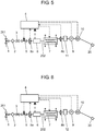
- a sanitary washing device according to a second embodiment of the invention and a toilet apparatus provided with the sanitary washing device with reference to Fig. 5 . Since the toilet apparatus is the same as that in the first embodiment, description thereof will be omitted.
- Fig. 5 is a diagram schematically illustrating a configuration of a main body of the sanitary washing device according to the second embodiment of the invention.
- the sanitary washing device according to the embodiment is different from that according to the first embodiment in that reservoir 11 is provided on the downstream side of electrolysis tank 6a forming sterilizer 6 and further on the downstream side of heat exchanger 7.
- reservoir 11 is provided on the downstream side of electrolysis tank 6a forming sterilizer 6 and further on the downstream side of heat exchanger 7.
- Other configurations and operations are the same as those according to the first embodiment.
- the same reference numerals will be given to the same components as those in the first embodiment, and descriptions thereof will be omitted.
- Reservoir 11 is provided to secure the contact time between the active species such as ozone water generated in electrolysis tank 6a and bacteria.
- a bacteria elimination performance of ozone water generated by sterilizer 6 can be typically determined by a CT value.
- the time (contact time T) required for sterilizing coli bacteria is one minute.
- the concentration of the active species is 0.2 ppm, only 1/10 minutes is enough for the contact time T with the bacteria. That is, this means the sterilization can be done if bacteria are brought into contact with the 0.2 ppm of active species for 6 seconds.
- reservoir 11 is provided on the downstream side of electrolysis tank 6a in the embodiment. In doing so, the contact time between the active species and bacteria is extended in reservoir 11. As a result, the sterilizing performance is further enhanced.
- reservoir 11 may be disposed at an arbitrary position as long as reservoir 11 is disposed on the downstream side of electrolysis tank 6a. In doing so, it is possible to obtain the same sterilizing performance. However, it is more preferable that reservoir 11 is provided on the downstream side of heat exchanger 7. The reason is that an activity of the ozone water is further enhanced by being heated by heat exchanger 7.
- a sanitary washing device according to a third embodiment of the invention and a toilet apparatus provided with the sanitary washing device with reference to Fig. 6 . Since the toilet apparatus is the same as that in the first embodiment, the description thereof will be omitted.
- Fig. 6 is a diagram schematically illustrating a configuration of a main body of the sanitary washing device according to the third embodiment of the invention.
- the sanitary washing device according to the embodiment is different from that according to the first embodiment in that active species remover 12 is provided on the downstream side of electrolysis tank 6a configuring sterilizer 6 and on the upstream side of positive-displacement pump 9.
- active species remover 12 is provided on the downstream side of electrolysis tank 6a configuring sterilizer 6 and on the upstream side of positive-displacement pump 9.
- Other configurations and operations are the same as those in the first embodiment.
- the same reference numerals will be given to the same components as those in the first embodiment, and the descriptions thereof will be omitted.
- Active species remover 12 is provided to remove or decompose active species such as ozone water generated in electrolysis tank 6a.
- controller 4 of the sanitary washing device controls the amount of generated active species such as ozone by a current or a voltage such that the concentration of active species generated becomes the concentration of active species that is equal to or less than several ppm that does not affect a human body.
- active species remover 12 configured of an activated carbon filter, for example, is provided on the downstream side of electrolysis tank 6a and on the upstream side of nozzle 20 according to the embodiment. In doing so, the active species at the concentration of equal to or greater than the prescribed value is removed or decomposed.
- the washing water is typically subjected to bacteria elimination in electrolysis tank 6a before reaching active species remover 12. Therefore, there is no particular problem even if the concentration of the active species is reduced by active species remover 12 in a state where the voltage is normally applied to sterilizer 6.
- the active species dissolved in the washing water is also diffused in a gas phase (air) when ejected from nozzle 20.
- a gas phase air
- active species remover 12 that is, in a case of using ozone as the active species, a small amount of ozone is diffused in the toilet room.
- active species remover 12 it is possible to reduce the ozone concentration in the gas phase in the toilet room by providing active species remover 12. As a result it is possible to provide a sanitary washing device with enhanced safety.
- active species remover 12 was provided on the downstream side of electrolysis tank 6a and on the upstream side of positive-displacement pump 9 as an example in the aforementioned embodiment, the invention is not limited thereto.
- active species remover 12 may be provided between positive-displacement pump 9 and nozzle 20, for example, and the same effects can be achieved.
- the invention is not limited thereto.
- the invention is not particularly limited as long as the active species can be removed or decomposed by the configuration.
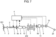
- a sanitary washing device according to a fourth embodiment of the invention and a toilet apparatus provided with the sanitary washing device with reference to Fig. 7 . Since the toilet apparatus is the same as that in the first embodiment, the description thereof will be omitted.
- Fig. 7 is a diagram schematically illustrating a configuration of a main body of the sanitary washing device according to the fourth embodiment of the invention.
- the sanitary washing device according to the embodiment is different from that according to the second embodiment in that scale pulverizer 13 is disposed on the downstream side of electrolysis tank 6a.
- Other configurations and operations are the same as those in the second embodiment.
- the same reference numerals will be given to the same components as those in the second embodiment, and descriptions thereof will be omitted.
- scale pulverizer 13 is configured to suppress scale components, which have been generated by electrolysis in electrolysis tank 6a configuring sterilizer 6, from flowing into washing water flow path 202 in a later stage than electrolysis tank 6a and blocking washing water flow path 202. That is, the embodiment is configured such that the electrolysis is performed while polarities of currents applied to anode electrode 6b and cathode electrode 6c are inverted. In doing so, adhesion of the scale components to cathode electrode 6c is avoided.
- scale pulverizer 13 is disposed on the downstream side of electrolysis tank 6a in the embodiment.
- Scale pulverizer 13 pulverizes the generated scale or the scale removed from cathode electrode 6c into fine particles. In doing so, it is possible to suppress occurrence of the blocking or the failure of heat exchanger 7, positive-displacement pump 9, or the like in advance.
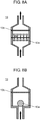
- Fig. 8A is a sectional view illustrating the scale pulverizer according to the embodiment.
- Fig. 8B is a sectional view of another scale pulverizer 13 according to the embodiment.
- scale pulverizer 13 is configured of at least pulverizer 13a and strainer 13b as illustrated in Fig. 8A .
- Pulverizer 13a is configured to have a propeller shape, for example, and pulverizes scale contained in washing water in scale pulverizer 13. Pulverizer 13a is not limited to the propeller shape and may have any shape as long as pulverizer 13a can pulverize the scale with the shape.
- pulverizer 13a is rotated by a water flow of the washing water flowing in scale pulverizer 13. Then, scale is pulverized into fine particles by the rotation of pulverizer 13a.
- Pulverizer 13a of scale pulverizer 13 does not necessarily have a propeller shape.
- pulverizer 13a may have a ball shape with a larger diameter than the inner diameter of piping as illustrated in Fig. 8B .
- pulverizer 13a moves in scale pulverizer 13 by the water flow in scale pulverizer 13. Then, scale is pulverized into fine particles by movement of pulverizer 13a.
- the scale pulverized by pulverizer 13a is discharged from scale pulverizer 13 via strainer 13b.
- the scale which has not been pulverized by pulverizer 13a is trapped by strainer 13b. Therefore, scale is not discharged from scale pulverizer 13.
- the scale trapped by strainer 13b is diffused by turbulence of the washing water occurring in scale pulverizer 13. Then, the diffused scale is repeatedly brought into contact with pulverizer 13a and is then pulverized. In doing so, the scale is reliably pulverized into fine particles. As a result, occurrence of the blocking or the failure of heat exchanger 7, positive-displacement pump 9, or the like can be more reliably suppressed.
- strainer 13b is formed of metal such as stainless steel with a mesh from 10 to 200 or synthesized resin, for example.
- Strainer 13b is preferably formed of a material such as fluorine resin, Teflon (registered trademark), or polystyrene. The reason is that the aforementioned materials have small surface free energy and scale does not easily adhere. In doing so, the scale is easily diffused in scale pulverizer 13. Therefore, the configuration is further preferable in which the propeller shape is employed as the shape of pulverizer 13a.
- pulverizer 13a is configured to have a ball shape or the like
- the mesh shape is selected for strainer 13b to increase the surface free energy of the material in order to increase the contact rate between pulverizer 13a and scale.
- the scale is made to adhere to strainer 13b with the mesh shape.
- the scale adhering to strainer 13b is pulverized by bringing pulverizer 13a with the ball shape illustrated in Fig. 8B into contact with the scale. That is, in the case of scale pulverizer 13 illustrated in Fig. 8B , it is also effective to increase the contact rate between pulverizer 13a and the scale by making the scale adhere to strainer 13b.
- the diameter of pulverizer 13a is set to be larger than that of washing water flow path 202 such that washing water flow path 202 is not blocked.
- the ball as pulverizer 13a is preferably configured of a material with a relatively low specific gravity such as synthesized resin in order that pulverizer 13a can freely move by the water flow. At this time, it is more preferable to form the inside of the ball as pulverizer 13a into a hollow shape to reduce the weight.
- scale pulverizer 13 is provided on the downstream side of sterilizer 6 and on the upstream side of heat exchanger 7. Then, scale pulverizer 13 pulverizes the scale discharged from electrolysis tank 6a into fine particles. In doing so, it is possible to avoid the blocking or the failure of the flow path of heat exchanger 7, positive-displacement pump 9, or the like installed on the downstream side of electrolysis tank 6a configuring sterilizer 6.
- scale pulverizer 13 was configured of pulverizer 13a and strainer 13b
- the invention is not limited thereto. That is, any configuration is applicable as long as the scale can be pulverized.
- an ultrasonic element or the like may be provided as scale pulverizer 13 to pulverize the scale by ultrasonic vibration, and the same effects can be achieved.
- a sanitary washing device according to a fifth embodiment of the invention and a toilet apparatus provided with the sanitary washing device with reference to Fig. 9 . Since the toilet apparatus is the same as that in the first embodiment, the description thereof will be omitted.
- Fig. 9 is a diagram schematically illustrating a configuration of a main body of the sanitary washing device according to the fifth embodiment of the invention.
- the sanitary washing device according to the embodiment is different from that according to the second embodiment in that discharge valve 14 is provided on the downstream side of electrolysis tank 6a.
- discharge valve 14 is provided on the downstream side of electrolysis tank 6a.
- Other configurations are the same as those in the second embodiment.
- the same reference numerals will be given to the same components as those in the second embodiment, and the descriptions thereof will be omitted.
- Discharge valve 14 operates to discharge washing water flowing into the downstream side of sterilizer 6 and containing washing water to a toilet bowl.
- discharge valve 14 discharge scale removed from cathode electrode 6c, to which the scale has adhered, to the toilet bowl by polarity inversion control of currents applied to electrodes of sterilizer 6.
- Such a configuration prevents the water containing the scale from flowing into heat exchanger 7, nozzle 20, and the like.
- it is possible to suppress the scale components generated in electrolysis tank 6a from flowing through washing water flow path 202 on the downstream side beyond electrolysis tank 6a and blocking washing water flow path 202 in advance.
- the polarity inversion control for inverting polarities is performed between anode electrode 6b and cathode electrode 6c in the embodiment in the same manner as in the second embodiment. In doing so, adhesion of the scale to cathode electrode 6c is suppressed.
- anode electrode 6b that generates the active species such as ozone has a negative potential. Therefore, the active species such as ozone is not generated at anode electrode 6b.
- the flow path through which the washing water flows is switched by discharge valve 14. In doing so, the washing water is discharged to toilet bowl 600 without causing the washing water to flow through heat exchanger 7 and nozzle 20.
- the washing water may or may not be made to pass through washing water flow path 202.
- the control is performed so as to discharge the washing water containing removed scale in electrolysis tank 6a after the completion of the electrolysis. It is preferable to further discharge the water while the washing water is further made to pass after the discharging even in the case where the control is performed so as to discharge the water after the completion of the electrolysis. In doing so, it is possible to flush the scale components adhering to the surfaces of the electrodes of sterilizer 6.
- electrolysis tank 6a After flushing the surfaces of the electrodes, it is preferable to fill electrolysis tank 6a with the washing water by closing discharge valve 14. In doing so, it is possible to prevent the washing water adhering to the surfaces of the electrodes from being dried when electrolysis tank 6a is not used for a long period of time. As a result, it is possible to suppress the scale components contained in the washing water from adhering to the surfaces of the electrodes of sterilizer 6.
- the sanitary washing device may include a nozzle that moves to a predetermined washing position and sprays washing water, a washing water flow path that guides the washing water to the nozzle, a pump that causes the nozzle to eject the washing water, and a heater that heats the washing water.
- the sanitary washing device may include a sterilizer that is disposed on the upstream side of the heater for sterilizing the washing water and a controller that controls the pump, the heater, and the sterilizer.
- the sterilizer is disposed on the upstream side of the heater. In doing so, it is possible to enhance solubility of the active species, such as ozone, generated in the sterilizer in the washing water. As a result, it is possible to further enhance the sterilizing ability. Furthermore, the washing water with the active species such as ozone dissolved at a higher rate is heated by the heater. In doing so, the reactivity of the active species is further enhanced. As a result, it is possible to achieve a higher sterilizing property.
- the sanitary washing device may include a water temperature detector that detects a water temperature of the washing water, and the controller may control the sterilizer based on the water temperature detected by the water temperature detector. In doing so, it is possible to stably secure always constant sterilizing ability without being affected by the water temperature.
- the sanitary washing device according to the invention may generate electrolysis water by the sterilizer electrolyzing the washing water. In doing so, it is not necessary to add a necessary chemical to the sterilizer. As a result, it is possible to realize maintenance free and to thereby enhance usability.
- the electrolysis water generated by the sterilizer may be ozone water. In doing so, it is possible to maintain the high sterilizing property without depending on water quality of the washing water.
- the sterilizer is configured of at least two electrodes, and the electrodes each include an electrode catalyst on a surface of a metal board.
- the electrode catalyst of at least one of the electrodes may be formed of tantalum oxide or tantalum oxide and platinum.
- At least one of the electrodes may include a metal layer for suppressing corrosion of the metal board on the surface of the metal board and include the electrode catalyst on the metal layer. In doing so, it is possible to extend the electrode duration time of the sterilizer.
- the metal layer may be included at least any of platinum, iridium, ruthenium, and niobium. In doing so, it is possible to further extend the electrode duration time of the sterilizer.
- a reservoir may be provided on the downstream side of the sterilizer.
- an active species remover may be provided on a downstream side of the sterilizer. In doing so, it is possible to secure safety of a human body such as a private area and skin even in a case where the active species is generated at a high concentration or in a case where the private area is washed for a long period of time.
- a scale pulverizer that pulverizes scale generated by the sterilizer may be provided on a downstream side of the sterilizer.
- the scale generated in the electrolysis tank of the sterilizer is pulverized into fine particles.
- a discharge valve may be provided on a downstream side of the sterilizer, and a scale generated by the sterilizer may be discharged to the toilet bowl by the discharge valve. In doing so, it is possible to suppress the occurrence of the failures, such as blocking or an erroneous operation, due to the scale adhering to the washing water flow path, the heat exchanger, the positive-displacement pump, or the like in advance.
- the invention enables sterilization of supplied water and stable supply thereof. Therefore, the invention is useful not only for a warm water washing toilet seat but also for purposes such as a sanitary washing device for faces, heads, hands, feet, and the like or a washing device for pets or objects other than living creatures.
Landscapes
- Health & Medical Sciences (AREA)
- Public Health (AREA)
- Molecular Biology (AREA)
- Epidemiology (AREA)
- Life Sciences & Earth Sciences (AREA)
- Engineering & Computer Science (AREA)
- Hydrology & Water Resources (AREA)
- Water Supply & Treatment (AREA)
- Water Treatment By Electricity Or Magnetism (AREA)
- Bidet-Like Cleaning Device And Other Flush Toilet Accessories (AREA)
Applications Claiming Priority (3)
| Application Number | Priority Date | Filing Date | Title |
|---|---|---|---|
| JP2014092422 | 2014-04-28 | ||
| JP2015040852A JP2015222003A (ja) | 2014-04-28 | 2015-03-03 | 衛生洗浄装置 |
| PCT/JP2015/002136 WO2015166642A1 (fr) | 2014-04-28 | 2015-04-20 | Dispositif de lavage sanitaire |
Publications (2)
| Publication Number | Publication Date |
|---|---|
| EP3138971A1 true EP3138971A1 (fr) | 2017-03-08 |
| EP3138971A4 EP3138971A4 (fr) | 2017-09-06 |
Family
ID=54358388
Family Applications (1)
| Application Number | Title | Priority Date | Filing Date |
|---|---|---|---|
| EP15785527.1A Ceased EP3138971A4 (fr) | 2014-04-28 | 2015-04-20 | Dispositif de lavage sanitaire |
Country Status (4)
| Country | Link |
|---|---|
| EP (1) | EP3138971A4 (fr) |
| JP (1) | JP2015222003A (fr) |
| CN (1) | CN105992853B (fr) |
| WO (1) | WO2015166642A1 (fr) |
Families Citing this family (6)
| Publication number | Priority date | Publication date | Assignee | Title |
|---|---|---|---|---|
| JP6812654B2 (ja) * | 2016-03-31 | 2021-01-13 | アイシン精機株式会社 | 衛生洗浄装置 |
| CN106869273A (zh) * | 2017-02-21 | 2017-06-20 | 中山市爱马仕洁具有限公司 | 一种采用臭氧水装置的智能座便器 |
| JP7100840B2 (ja) * | 2018-02-16 | 2022-07-14 | 学校法人順天堂 | トイレ装置 |
| JP7343854B2 (ja) * | 2018-12-27 | 2023-09-13 | 青島海爾洗衣机有限公司 | 洗濯機 |
| JP7572673B2 (ja) * | 2020-09-17 | 2024-10-24 | 青島海爾洗衣机有限公司 | オゾン水散布装置 |
| WO2025205096A1 (fr) * | 2024-03-29 | 2025-10-02 | Toto株式会社 | Dispositif d'évacuation d'eau reformée et dispositif de toilettes équipé dudit dispositif |
Family Cites Families (21)
| Publication number | Priority date | Publication date | Assignee | Title |
|---|---|---|---|---|
| JPH07313980A (ja) * | 1994-05-27 | 1995-12-05 | Tdk Corp | イオン水生成装置用電極およびその製造方法ならびにイオン水生成装置 |
| US5686051A (en) * | 1994-11-11 | 1997-11-11 | Kabushiki Kaisha Kobe Seiko Sho | Ozone water production apparatus |
| CA2355769A1 (fr) * | 1998-12-16 | 2000-06-22 | Lynntech, Inc. | Elimination des micro-organismes a un point d'utilisation de sources d'eau potable |
| JP2001279776A (ja) * | 2000-03-29 | 2001-10-10 | Toto Ltd | 人体局部洗浄装置 |
| EP1553055A1 (fr) * | 2004-01-07 | 2005-07-13 | HomeFlow Switzerland Distribution SA | Procédé et installation de purification d'eau |
| JP2005336856A (ja) * | 2004-05-27 | 2005-12-08 | Aisin Seiki Co Ltd | トイレ装置 |
| JP4554542B2 (ja) * | 2006-03-09 | 2010-09-29 | 石福金属興業株式会社 | 電解用電極 |
| JP2007283180A (ja) * | 2006-04-14 | 2007-11-01 | Ozotech:Kk | オゾン水生成装置およびオゾン水生成方法 |
| WO2007125662A1 (fr) * | 2006-04-28 | 2007-11-08 | Panasonic Corporation | Dispositif de lavage sanitaire |
| JP2008057855A (ja) * | 2006-08-31 | 2008-03-13 | Matsushita Electric Ind Co Ltd | 流体加熱装置およびそれを用いた給湯装置 |
| JP2009138359A (ja) * | 2007-12-04 | 2009-06-25 | Panasonic Corp | 衛生洗浄装置 |
| JP2008232616A (ja) * | 2008-04-16 | 2008-10-02 | Matsushita Electric Ind Co Ltd | 熱交換器およびそれを備えた衛生洗浄装置 |
| CN102076918B (zh) * | 2008-07-03 | 2012-12-26 | 松下电器产业株式会社 | 卫生清洗装置 |
| EP3680404B1 (fr) * | 2008-09-11 | 2023-09-06 | Toto Ltd. | Dispositif de lavage sanitaire |
| WO2011016389A1 (fr) * | 2009-08-06 | 2011-02-10 | Toto株式会社 | Dispositif de lavage sanitaire |
| JP5601570B2 (ja) * | 2009-08-06 | 2014-10-08 | Toto株式会社 | 衛生洗浄装置 |
| JP2012082615A (ja) * | 2010-10-12 | 2012-04-26 | Toto Ltd | 衛生洗浄装置 |
| JP2012125715A (ja) * | 2010-12-16 | 2012-07-05 | Toto Ltd | 電気分解装置および衛生洗浄装置 |
| JP5812250B2 (ja) * | 2011-03-30 | 2015-11-11 | Toto株式会社 | 衛生洗浄装置 |
| JP5154707B1 (ja) * | 2012-08-06 | 2013-02-27 | 日科ミクロン株式会社 | オゾン水用温度計及びオゾン水生成装置 |
| JP3180399U (ja) * | 2012-08-07 | 2012-12-20 | 株式会社エコ・プランナー | 浄水器 |
-
2015
- 2015-03-03 JP JP2015040852A patent/JP2015222003A/ja active Pending
- 2015-04-20 EP EP15785527.1A patent/EP3138971A4/fr not_active Ceased
- 2015-04-20 CN CN201580008634.4A patent/CN105992853B/zh active Active
- 2015-04-20 WO PCT/JP2015/002136 patent/WO2015166642A1/fr not_active Ceased
Also Published As
| Publication number | Publication date |
|---|---|
| CN105992853A (zh) | 2016-10-05 |
| JP2015222003A (ja) | 2015-12-10 |
| EP3138971A4 (fr) | 2017-09-06 |
| WO2015166642A1 (fr) | 2015-11-05 |
| CN105992853B (zh) | 2018-05-29 |
Similar Documents
| Publication | Publication Date | Title |
|---|---|---|
| EP3138971A1 (fr) | Dispositif de lavage sanitaire | |
| JP3619828B2 (ja) | 電解用電極及びその製造方法及び電解用電極を用いた電解方法及び電解水生成装置 | |
| TW201207200A (en) | Sanitary cleansing device | |
| CN107109828A (zh) | 自动水龙头装置 | |
| CN107109830A (zh) | 水龙头装置 | |
| JP6106396B2 (ja) | 殺菌水生成装置 | |
| CN103194765A (zh) | 杀菌水生成装置 | |
| JP7005517B2 (ja) | 電解水生成装置 | |
| JP3819860B2 (ja) | オゾン生成装置 | |
| JP6617864B2 (ja) | 除菌水生成装置 | |
| US20110290740A1 (en) | Waste treatment and disinfection unit | |
| JP2000343081A (ja) | 便器殺菌装置 | |
| JP5954681B2 (ja) | 衛生洗浄装置 | |
| KR101561303B1 (ko) | 전극살균모듈을 이용한 식기세척기 | |
| JP6596862B2 (ja) | 除菌水生成装置 | |
| JP6918285B2 (ja) | 吐水装置 | |
| JP2006207328A (ja) | 洗浄水生成装置 | |
| JP2014061490A (ja) | 金属イオン酸性水添加装置および水回り機器 | |
| JP5515632B2 (ja) | 洗浄装置 | |
| KR20070088410A (ko) | 의료기기 및 진료기구 살균 세척기 | |
| JP6614405B2 (ja) | 吐水装置 | |
| JP2017172123A (ja) | 除菌水吐出装置 | |
| JP5172098B2 (ja) | 空気除菌装置 | |
| JP2003290768A (ja) | 尿石付着防止装置 | |
| TWM617105U (zh) | 自發電消毒水產生裝置 |
Legal Events
| Date | Code | Title | Description |
|---|---|---|---|
| PUAI | Public reference made under article 153(3) epc to a published international application that has entered the european phase |
Free format text: ORIGINAL CODE: 0009012 |
|
| 17P | Request for examination filed |
Effective date: 20161018 |
|
| AK | Designated contracting states |
Kind code of ref document: A1 Designated state(s): AL AT BE BG CH CY CZ DE DK EE ES FI FR GB GR HR HU IE IS IT LI LT LU LV MC MK MT NL NO PL PT RO RS SE SI SK SM TR |
|
| AX | Request for extension of the european patent |
Extension state: BA ME |
|
| RIC1 | Information provided on ipc code assigned before grant |
Ipc: E03D 9/08 20060101AFI20170411BHEP |
|
| DAV | Request for validation of the european patent (deleted) | ||
| DAX | Request for extension of the european patent (deleted) | ||
| A4 | Supplementary search report drawn up and despatched |
Effective date: 20170808 |
|
| RIC1 | Information provided on ipc code assigned before grant |
Ipc: E03D 9/08 20060101AFI20170802BHEP |
|
| 17Q | First examination report despatched |
Effective date: 20180803 |
|
| REG | Reference to a national code |
Ref country code: DE Ref legal event code: R003 |
|
| STAA | Information on the status of an ep patent application or granted ep patent |
Free format text: STATUS: THE APPLICATION HAS BEEN REFUSED |
|
| 18R | Application refused |
Effective date: 20190715 |