EP3143682B1 - Magnetkupplung - Google Patents
Magnetkupplung Download PDFInfo
- Publication number
- EP3143682B1 EP3143682B1 EP15728385.4A EP15728385A EP3143682B1 EP 3143682 B1 EP3143682 B1 EP 3143682B1 EP 15728385 A EP15728385 A EP 15728385A EP 3143682 B1 EP3143682 B1 EP 3143682B1
- Authority
- EP
- European Patent Office
- Prior art keywords
- permanent magnet
- coupling
- magnetic coupling
- diverting element
- magnetic
- Prior art date
- Legal status (The legal status is an assumption and is not a legal conclusion. Google has not performed a legal analysis and makes no representation as to the accuracy of the status listed.)
- Active
Links
Images

Classifications
-
- F—MECHANICAL ENGINEERING; LIGHTING; HEATING; WEAPONS; BLASTING
- F04—POSITIVE - DISPLACEMENT MACHINES FOR LIQUIDS; PUMPS FOR LIQUIDS OR ELASTIC FLUIDS
- F04D—NON-POSITIVE-DISPLACEMENT PUMPS
- F04D13/00—Pumping installations or systems
- F04D13/02—Units comprising pumps and their driving means
- F04D13/06—Units comprising pumps and their driving means the pump being electrically driven
- F04D13/0606—Canned motor pumps
- F04D13/0613—Special connection between the rotor compartments
-
- A—HUMAN NECESSITIES
- A61—MEDICAL OR VETERINARY SCIENCE; HYGIENE
- A61M—DEVICES FOR INTRODUCING MEDIA INTO, OR ONTO, THE BODY; DEVICES FOR TRANSDUCING BODY MEDIA OR FOR TAKING MEDIA FROM THE BODY; DEVICES FOR PRODUCING OR ENDING SLEEP OR STUPOR
- A61M60/00—Blood pumps; Devices for mechanical circulatory actuation; Balloon pumps for circulatory assistance
- A61M60/10—Location thereof with respect to the patient's body
- A61M60/122—Implantable pumps or pumping devices, i.e. the blood being pumped inside the patient's body
-
- A—HUMAN NECESSITIES
- A61—MEDICAL OR VETERINARY SCIENCE; HYGIENE
- A61M—DEVICES FOR INTRODUCING MEDIA INTO, OR ONTO, THE BODY; DEVICES FOR TRANSDUCING BODY MEDIA OR FOR TAKING MEDIA FROM THE BODY; DEVICES FOR PRODUCING OR ENDING SLEEP OR STUPOR
- A61M60/00—Blood pumps; Devices for mechanical circulatory actuation; Balloon pumps for circulatory assistance
- A61M60/20—Type thereof
- A61M60/205—Non-positive displacement blood pumps
-
- A—HUMAN NECESSITIES
- A61—MEDICAL OR VETERINARY SCIENCE; HYGIENE
- A61M—DEVICES FOR INTRODUCING MEDIA INTO, OR ONTO, THE BODY; DEVICES FOR TRANSDUCING BODY MEDIA OR FOR TAKING MEDIA FROM THE BODY; DEVICES FOR PRODUCING OR ENDING SLEEP OR STUPOR
- A61M60/00—Blood pumps; Devices for mechanical circulatory actuation; Balloon pumps for circulatory assistance
- A61M60/40—Details relating to driving
- A61M60/403—Details relating to driving for non-positive displacement blood pumps
- A61M60/419—Details relating to driving for non-positive displacement blood pumps the force acting on the blood contacting member being permanent magnetic, e.g. from a rotating magnetic coupling between driving and driven magnets
-
- A—HUMAN NECESSITIES
- A61—MEDICAL OR VETERINARY SCIENCE; HYGIENE
- A61M—DEVICES FOR INTRODUCING MEDIA INTO, OR ONTO, THE BODY; DEVICES FOR TRANSDUCING BODY MEDIA OR FOR TAKING MEDIA FROM THE BODY; DEVICES FOR PRODUCING OR ENDING SLEEP OR STUPOR
- A61M60/00—Blood pumps; Devices for mechanical circulatory actuation; Balloon pumps for circulatory assistance
- A61M60/80—Constructional details other than related to driving
- A61M60/802—Constructional details other than related to driving of non-positive displacement blood pumps
- A61M60/827—Sealings between moving parts
-
- H—ELECTRICITY
- H02—GENERATION; CONVERSION OR DISTRIBUTION OF ELECTRIC POWER
- H02K—DYNAMO-ELECTRIC MACHINES
- H02K49/00—Dynamo-electric clutches; Dynamo-electric brakes
- H02K49/10—Dynamo-electric clutches; Dynamo-electric brakes of the permanent-magnet type
- H02K49/104—Magnetic couplings consisting of only two coaxial rotary elements, i.e. the driving element and the driven element
- H02K49/108—Magnetic couplings consisting of only two coaxial rotary elements, i.e. the driving element and the driven element with an axial air gap
-
- H—ELECTRICITY
- H02—GENERATION; CONVERSION OR DISTRIBUTION OF ELECTRIC POWER
- H02K—DYNAMO-ELECTRIC MACHINES
- H02K7/00—Arrangements for handling mechanical energy structurally associated with dynamo-electric machines, e.g. structural association with mechanical driving motors or auxiliary dynamo-electric machines
- H02K7/003—Couplings; Details of shafts
-
- F—MECHANICAL ENGINEERING; LIGHTING; HEATING; WEAPONS; BLASTING
- F16—ENGINEERING ELEMENTS AND UNITS; GENERAL MEASURES FOR PRODUCING AND MAINTAINING EFFECTIVE FUNCTIONING OF MACHINES OR INSTALLATIONS; THERMAL INSULATION IN GENERAL
- F16D—COUPLINGS FOR TRANSMITTING ROTATION; CLUTCHES; BRAKES
- F16D27/00—Magnetically- or electrically- actuated clutches; Control or electric circuits therefor
- F16D27/01—Magnetically- or electrically- actuated clutches; Control or electric circuits therefor with permanent magnets
-
- H—ELECTRICITY
- H02—GENERATION; CONVERSION OR DISTRIBUTION OF ELECTRIC POWER
- H02K—DYNAMO-ELECTRIC MACHINES
- H02K5/00—Casings; Enclosures; Supports
- H02K5/04—Casings or enclosures characterised by the shape, form or construction thereof
- H02K5/12—Casings or enclosures characterised by the shape, form or construction thereof specially adapted for operating in liquid or gas
- H02K5/128—Casings or enclosures characterised by the shape, form or construction thereof specially adapted for operating in liquid or gas using air-gap sleeves or air-gap discs
Definitions
- the invention relates to a magnetic coupling for transmitting torque along an axis of rotation, with two relatively rotatable coupling parts, wherein a drive-side coupling part has a drive-side permanent magnet and an output side coupling part has a drive side permanent magnet along the axis of rotation opposite and spaced therefrom disposed output side permanent magnet, wherein one of Clutch parts comprises an at least partially ferromagnetic Umleitelement which is rotatably connected to the permanent magnet of the coupling part, wherein a part of the Umleitelements is arranged radially outside of the opposite permanent magnet.
- the invention relates to a compact magnetic coupling between separate functional areas without housing feedthrough.
- This structure essentially corresponds to the type of magnetic coupling generally known as a front-end rotary coupling.
- Characteristic of this type of coupling are the axially adjacent, often mirror-inverted, permanent magnets of the two coupling parts. As a rule, the two coupling parts are separated by a plane separating surface, which is perpendicular to the axis of rotation.
- a known alternative to this type of coupling is the central rotary coupling, which has two coaxial with each other arranged hollow cylindrical coupling parts.
- the basic structure of both types of coupling for example, the EP 0 039 777 A2 be removed.
- Central swivel couplings have the advantage of better torque transmission, but are difficult and costly to produce with increasing miniaturization due to the necessary thin-walled hollow cylindrical coupling parts and corresponding flat permanent magnets.
- face rotary couplings show a disproportionate deterioration of the torque transmission when the size is reduced, ie with smaller coupling dimensions not only the available magnetized volume but also the radius decisive for the transmitted torque decreases.
- One possible field of application of the magnetic coupling according to the invention, in which small dimensions of the coupling are particularly desirable, is in particular the use as an implanted medical device, in particular as a blood pump, preferably as a cardiac blood pump or as a cardiac catheter pump.
- a blood pump is already out of the EP 0 904 117 B1 known, wherein the magnetic coupling shown there between the drive and the pump rotor is designed in known manner as a front-end rotary coupling.
- the DE 11 2008 002854 T5 shows a power transmission device for transmitting a rotational driving force.
- this power transmission device comprises a roller with a drive-side permanent magnet and an opposite hub with a driven-side permanent magnet.
- the permanent magnets are arranged opposite one another along an axis of rotation about the drive shaft.
- the roller has an outer ring which surrounds the hub radially on the outside and consists of a magnetic material, for example iron.
- the diverting element has at least one diamagnetic separation which divides the diverting element into at least two ferromagnetic sections. With such a separation, a magnetic short circuit in the bypass element can be avoided.
- the diverting element can - like the outer coupling part of a central rotary coupling - pot-shaped or hollow cylinder-shaped and the other one Surrounding the coupling part circumferentially, ie it preferably extends radially outside of both permanent magnets.
- the diverting element may be formed, for example, as a thin-walled hollow cylinder, so that the magnetized volume of the face rotary coupling remains largely the same while at the same time a transferable torque comparable to a central rotary coupling can be achieved between the diverting element and the permanent magnet located at a distance therefrom.
- the magnetization direction of the permanent magnets is preferably aligned perpendicular to the axis of rotation, ie the magnetic poles are in the circumferential direction from south to north and are - at least in a two-pole design - with respect to the axis of rotation diametrically opposite.
- the diverting element radially bundles magnetic field lines emanating from the permanent magnets and additionally strengthens the magnetic force between the coupling parts because of the ferromagnetic material of the diverting element.
- the compression of the magnetic field lines in the ferromagnetic material increases the magnetic force for transmitting the torque.
- the respective number of poles are set for both magnets.
- the permanent magnets each have two semi-cylindrical magnetic poles.
- the separation may be carried out as a diamagnetic separating strip along a plane intersecting the permanent magnet centrally and transverse to the direction of magnetization, i. the separating strip divides the diverting element into two halves.
- the diverting element When the diverting element extends to a rear side of the permanent magnet, which is remote from the permanent magnet, the magnetization of the diverting element and thus the transmittable torque can be additionally increased.
- the diverting element has a hollow cylindrical shell and is preferably formed with a arranged at substantially half the height of the shell intermediate bottom.
- the diverting element has a substantially H-shaped longitudinal section, wherein the intermediate bottom forms the transverse web lying perpendicular to the axis of rotation, so that cup-shaped recesses are formed on both sides of the intermediate bottom.
- a permanent magnet is added and connected in a rotationally fixed manner.
- a particularly high concentration of magnetic field lines in the diverting element can be achieved if a diamagnetic shielding element is arranged on a rear side of the permanent magnet, which is remote from the opposite permanent magnet and is permanently connected to the diverting element. As a result, field lines extending outside the coupling parts can be avoided and associated losses can be reduced.
- a diamagnetic shielding element is arranged on a front side of the permanent magnet facing the front of the non-rotatably connected to the diverting permanent magnet, in particular in an area centered about the axis of rotation, which connects preferably peripherally or radially outside to the diverting ,
- a deflection of the magnetic field can be achieved in regions located radially at a greater distance from the axis of rotation, so that the torque transmitted at a given magnetic force is increased.
- the two coupling parts are hermetically separated.
- a hermetic separation can be achieved, for example, by a hermetic wall between the two coupling parts, which wall should be neither magnetic nor electrically conductive. This must not necessarily be part of a housing of the coupling, but can for example connect to a housing.
- the present magnetic coupling can also be used without hermetic separation, for example for safety clutches, ie for limiting the transmitted torque.
- At least one of the coupling parts is housed in a substantially non-magnetic and electrically non-conductive housing for the hermetic separation of the two coupling parts. With such a housing losses due to a re-magnetization of the housing or induced eddy currents in the housing can be avoided.
- the present magnetic coupling can be used particularly advantageously in a pump with a drive and a pump rotor, wherein the pump rotor is connected via the magnetic coupling to the drive.
- the pump thus obtained can be designed to be particularly compact, at the same time relatively high torque transmitted with a correspondingly advantageous pump power.
- a magnetic coupling 1 is shown, which connects a drive shaft 2 with an output shaft 3 for non-contact transmission of torque M, M '.
- the two waves 2, 3 lie on a common axis of rotation 4, so that a drive-side coupling part 5 is rotatably mounted relative to a driven-side coupling part 6.
- the output-side coupling part 6 comprises a driven-side two-pole permanent magnet 7, which is rotatably connected to the output shaft 3, in particular to the output shaft 3 is attached (see. Fig. 2 ).
- the driven-side permanent magnet 7 is circumferentially of a substantially cup-shaped Umleitelement 8 with a hollow cylindrical shell 8 'and the shell 8' at one end final, disc-shaped, substantially flat bottom 8 "(see.
- Fig. 2 surround.
- a distance or gap is provided between the output-side permanent magnet 7 and the diverting element 8, so that the output-side coupling part 6 is coupled without contact with the drive-side coupling part 5.
- the diverting element 8 consists largely of ferromagnetic material.
- the jacket 8 'of the diverting element 8 is interrupted only in a narrow angular range by a diamagnetic separation 9 and the separation 9 also extends across the bottom 8''.
- the separation 9 divides the diverting element 8 essentially into two ferromagnetic halves or half shells. A cutting plane running through the separation 9 is thus perpendicular to a magnetization direction of the drive-side two-pole permanent magnet 10 connected to the bypass element 8 (cf. Fig. 2 ).
- the ferromagnetic portions 11, 12 of the bypass 8 are therefore magnetized according to the drive-side permanent magnet 10.
- the drive-side frusto-conical bevel 13 of the diverting element 8 With the drive-side frusto-conical bevel 13 of the diverting element 8, a magnetic field gradient which is as homogeneous as possible is achieved in the diverting element 8, or any magnetization losses caused by inhomogeneities at the edges are reduced.
- Fig. 2 is the in Fig. 1 shown magnetic coupling 1 shown in longitudinal section, wherein additionally the drive side Coupling part 5 is separated by a housing 14 from the output side coupling part 6.
- the housing 14 forms a hermetic separation between the functional areas of the two coupling parts 5, 6.
- the drive-side coupling part 5 with the drive-side permanent magnet 10 and the Umleitelement 8 is rotatably received in the housing 14, the housing 14 of the cup-shaped recess in the diverter 8 approximately to a front side 15 of the drive-side permanent magnet 10 follows and even a correspondingly smaller cup-shaped recess 16 for receiving the driven-side coupling part 6 forms.
- the jacket 8'of the diverting 8 advantageously radially completely fills Through the bottom 8 "of the redirecting element 8 of ferromagnetic material, any field lines emerging to the back of the permanent magnet 10 are deflected via the diverting element 8 to the front side and thus contribute to the transmission of torque in Fig. 2 can be seen, the two permanent magnets 7, 10 attached to the respectively associated shafts 3, 2 or along the axis of rotation 4 of the shafts 3, 2 passes.
- FIG. 3 the magnetic coupling 1 is shown with respect to the bottom 8 "of the diverting element 8, the diamagnetic separation 9 extending across the bottom 8" dividing the bottom 8 "into two semicircular halves.
- Fig. 4 shows one opposite Fig. 2 extended variant of the magnetic coupling 1, wherein the front side 15 of the associated with the diverting 8 permanent magnet 10 is provided with a diamagnetic shield 17.
- the shielding 17 is a conclusion of the magnetic field lines between the two permanent magnets 7, 10 counteracted at low radii, ie in the vicinity of the axis of rotation 4.
- FIG. 6 and 7 a variant of the magnetic coupling 1 is shown, in which the ferromagnetic bottom 8 "of the diverting 8 (see. Fig. 2 and 4 ) is replaced by a diamagnetic shielding element 18 on the rear side 19 of the permanent magnet 10 connected to the diverting element 8.
- the shielding element 18 back exiting field lines of the magnetic field between the permanent magnets 7, 10 of the two coupling parts 5, 6 are avoided, so that at the outside and front, a correspondingly higher magnetic field is achieved.
- a separation 9 as in the ferromagnetic floor 8 "(see. Fig. 3 ) is not required in the shielding element 18.
- the jacket 8 'of the diverting element 8 has a taper 20 at the closed end, into which the shielding element 18 is fitted.
- FIG Fig. 8 and 9 Another alternative embodiment of the magnetic coupling 1 is shown in FIG Fig. 8 and 9
- the diverting element 8 here has, instead of the base 8 ", an intermediate bottom 21 approximately halfway up the jacket 8 '.
- the intermediate bottom 21 has - like the bottom 8" (cf. Fig. 3 ) - a transverse to the axis of rotation 4 extending separating strip 22.
- the diverting element 8 thus forms cup-shaped recesses 23, 24, wherein in the drive-side recess 23 of the drive-side permanent magnet 10 and subsequently thereto disc-shaped diamagnetic shielding member 25 is received and rotatably connected.
- the output side recess 24 accordingly surrounds the output side permanent magnet 7.
- the in Fig. 6 shown variant of the magnetic coupling 1 offers the variant according to Fig. 8 a better dimensional stability of the Umleitelements 8 and thus a higher mechanical strength of the magnetic coupling 1 in terms of manufacturing.
- a ferromagnetic bottom 26 comparable to the bottom 8 "of the diverting 8 according to FIGS. 2 and 3 is inserted into the drive-side recess 23.
- the inserted base 26 expediently also has a diamagnetic separating strip 27, which divides the bottom 26 into two semicircular halves and thus prevents a closure of the magnetic circuit between the two poles of the permanent magnet 10 via the rear side of the coupling part 5.
Landscapes
- Health & Medical Sciences (AREA)
- Engineering & Computer Science (AREA)
- Heart & Thoracic Surgery (AREA)
- Mechanical Engineering (AREA)
- Biomedical Technology (AREA)
- Cardiology (AREA)
- Anesthesiology (AREA)
- Hematology (AREA)
- Life Sciences & Earth Sciences (AREA)
- Animal Behavior & Ethology (AREA)
- General Health & Medical Sciences (AREA)
- Public Health (AREA)
- Veterinary Medicine (AREA)
- Power Engineering (AREA)
- General Engineering & Computer Science (AREA)
- Dynamo-Electric Clutches, Dynamo-Electric Brakes (AREA)
- External Artificial Organs (AREA)
Description
- Die Erfindung betrifft eine Magnetkupplung zur Drehmomentübertragung entlang einer Drehachse, mit zwei relativ zueinander drehbaren Kupplungsteilen, wobei ein antriebsseitiger Kupplungsteil einen antriebsseitigen Dauermagnet aufweist und ein abtriebsseitiger Kupplungsteil einen dem antriebsseitigen Dauermagnet entlang der Drehachse gegenüberliegenden und im Abstand davon angeordneten abtriebsseitigen Dauermagnet aufweist, wobei einer der Kupplungsteile ein zumindest teilweise ferromagnetisches Umleitelement umfasst, welches mit dem Dauermagnet des Kupplungsteils drehfest verbunden ist, wobei ein Teil des Umleitelements radial außerhalb des gegenüberliegenden Dauermagnets angeordnet ist. Insbesondere betrifft die Erfindung eine kompakte Magnetkupplung zwischen getrennten Funktionsbereichen ohne Gehäusedurchführung.
- Dieser Aufbau entspricht im Wesentlichen dem allgemein als Stirndrehkupplung bekannten Typ einer Magnetkupplung. Charakteristisch für diesen Kupplungstyp sind die axial benachbarten, häufig spiegelbildlich angeordneten, Dauermagnete der beiden Kupplungsteile. In der Regel sind die beiden Kupplungsteile dabei durch eine ebene Trennfläche, welche senkrecht auf die Drehachse steht, getrennt. Eine bekannte Alternative zu diesem Kupplungstyp ist die Zentraldrehkupplung, welche zwei koaxial ineinander angeordnete hohlzylinderförmige Kupplungsteile aufweist. Der grundsätzliche Aufbau beider Kupplungstypen kann beispielsweise der
EP 0 039 777 A2 entnommen werden. Zentraldrehkupplungen haben den Vorteil einer besseren Drehmomentübertragung, sind jedoch bei zunehmender Miniaturisierung aufgrund der notwendigen dünnwandigen hohlzylinderförmigen Kupplungsteile und entsprechend flache Dauermagnete nur schwierig und kostenintensiv herstellbar. Andererseits zeigen Stirndrehkupplungen bei einer Verkleinerung der Baugröße eine überproportionale Verschlechterung der Drehmomentübertragung, d.h. mit geringeren Kupplungsabmessungen sinkt nicht nur das verfügbare magnetisierte Volumen sondern auch der für das übertragene Drehmoment entscheidende Radius. - Ein mögliches Einsatzgebiet der erfindungsgemäßen Magnetkupplung, bei dem geringe Abmessungen der Kupplung besonders wünschenswert sind, ist insbesondere die Verwendung als implantiertes Medizingerät, insbesondere als Blutpumpe, vorzugsweise als Herzblutpumpe bzw. als Herzkatheterpumpe vorgesehen. Eine derartige Blutpumpe ist bereits aus der
EP 0 904 117 B1 bekannt, wobei die dort gezeigte Magnetkupplung zwischen dem Antrieb und dem Pumpenläufer in an sich bekannter Weise als Stirndrehkupplung ausgeführt ist.
DieDE 11 2008 002854 T5 zeigt eine Kraftübertragungsvorrichtung zum Übertragen einer rotatorischen Antriebskraft. Gemäß einer der Ausführungsformen umfasst diese Kraftübertragungsvorrichtung eine Rolle mit einem antriebsseitigen Dauermagnet sowie einer gegenüberliegenden Nabe mit einem abtriebseitigen Dauermagnet. Die Dauermagnete sind dabei entlang einer Drehachse um die Antriebswelle einander gegenüberliegend angeordnet. Die Rolle weist einen äußeren Ring auf, welcher die Nabe radial außenseitig umgibt und aus einem magnetischen Material, beispielsweise aus Eisen, besteht.
Gegenüber den bekannten Bauformen ist es Aufgabe der Erfindung, eine Magnetkupplung vorzuschlagen, welche bei vorgegebenen, besonders kompakten Abmessungen einerseits einfacher und kostengünstiger als vergleichbare Zentraldrehkupplungen herstellbar ist und andererseits eine gegenüber herkömmlichen Stirndrehkupplungen gesteigerte Effizienz hinsichtlich des übertragenen Drehmoments aufweist. - Diese Aufgabe wird bei der in Anspruch 1 definierten erfindungsgemässen Magnetkupplung dadurch gelöst, dass das Umleitelement zumindest eine diamagnetische Trennung aufweist, welche das Umleitelement in zumindest zwei ferromagnetische Abschnitte unterteilt. Mit einer solchen Trennung kann ein magnetischer Kurzschluss im Umleitelement vermieden werden. Das Umleitelement kann dabei - vergleichbar dem äußeren Kupplungsteil einer Zentraldrehkupplung - topf- bzw. hohlzylinderförmig ausgebildet sein und den jeweils anderen Kupplungsteil umfangseitig umgeben, d.h. es erstreckt sich vorzugsweise radial außerhalb beider Dauermagnete. Dabei kann das Umleitelement beispielsweise als dünnwandiger Hohlzylinder ausgebildet sein, sodass bei gleichbleibenden Abmessungen das magnetisierte Volumen der Stirndrehkupplung weitestgehend erhalten bleibt und zugleich zwischen dem Umleitelement und dem im Abstand davon gegenüberliegenden Dauermagnet ein einer Zentraldrehkupplung vergleichbar großes übertragbares Drehmoment erzielbar ist. Die Magnetisierungsrichtung der Dauermagnete ist dabei vorzugsweise senkrecht auf die Drehachse ausgerichtet, d.h. die Magnetpole verlaufen in Umfangsrichtung von Süd nach Nord und liegen sich - jedenfalls bei einer zweipoligen Ausführung - bezüglich der Drehachse diametral gegenüber. Durch das Umleitelement werden radial von den Dauermagneten ausgehende magnetische Feldlinien gebündelt und die magnetische Kraft zwischen den Kupplungsteilen wegen des ferromagnetischen Materials des Umleitelements zusätzlich verstärkt. Durch die Verdichtung der magnetischen Feldlinien im ferromagnetischen Material wird die magnetische Kraft zur Übertragung des Drehmoments vergrößert. Aufgrund des im Vergleich zu Zentraldrehkupplungen bei gleichen Kupplungsabmessungen größeren Volumens der Dauermagneten kann vorteilhafter Weise eine geringere axiale Erstreckung und somit geringere radiale Querkräfte auf die Lager der Kupplungsteile erzielt werden. Weitere vorteilhafte Ausgestaltungsformen der Erfindung sind in den abhängigen Ansprüchen 2 - 10 definiert. Eine kompakte Herstellung der Magnetkupplung mit einer zugleich vergleichsweise guten Drehmoment-Übertragungsfähigkeit kann erzielt werden, wenn die beiden Dauermagnete jeweils 2-, 4- oder 6-polige Dauermagnete sind. Um die Übertragungsfähigkeit des Drehmoments der Magnetkupplung zu optimieren, wird insbesondere in Abhängigkeit vom Durchmesser der Kupplung die jeweilige Polanzahl für beide Magnete festgelegt werden. Bei verhältnismäßig großen Magnetkupplungen ist auch eine höhere Polanzahl möglich. Im Falle der 2-poligen Ausgestaltung können die Dauermagnete jeweils zwei halbzylinderförmige Magnetpole aufweisen.
- Im Fall eines zweipoligen Dauermagnets kann die Trennung als diamagnetischer Trennstreifen entlang einer den Dauermagnet zentral und quer zur Magnetisierungsrichtung schneidenden Ebene ausgeführt sein, d.h. der Trennstreifen teilt das Umleitelement in zwei Hälften.
- Wenn sich das Umleitelement an eine dem gegenüberliegenden Dauermagnet abgewandten Rückseite des drehfest verbundenen Dauermagnets erstreckt, kann die Magnetisierung des Umleitelements und somit das übertragbare Drehmoment zusätzlich gesteigert werden.
- Darüber hinaus hat es sich als günstig herausgestellt, wenn das Umleitelement einen hohlzylinderförmigen Mantel aufweist und vorzugsweise mit einem auf im Wesentlichen halber Höhe des Mantels angeordneten Zwischenboden ausgebildet ist. Das Umleitelement weist in diesem Fall einen im Wesentlichen H-förmigen Längsschnitt auf, wobei der Zwischenboden den senkrecht auf die Drehachse liegenden Quersteg bildet, so dass beidseitig des Zwischenbodens topfförmige Ausnehmungen gebildet sind. In einer dieser Ausnehmungen ist ein Dauermagnet aufgenommen und drehfest verbunden.
- Eine besonders hohe Konzentration von Magnetfeldlinien im Umleitelement kann erzielt werden, wenn an einer dem gegenüberliegenden Dauermagnet abgewandten Rückseite des drehfest mit dem Umleitelement verbundenen Dauermagnets ein diamagnetisches Abschirmelement angeordnet ist. Dadurch können außerhalb der Kupplungsteile verlaufende Feldlinien vermieden und damit verbundene Verluste reduziert werden.
- Weiters hat es sich als günstig herausgestellt, wenn an einer dem gegenüberliegenden Dauermagnet zugewandten Vorderseite des drehfest mit dem Umleitelement verbundenen Dauermagnets, insbesondere in einem um die Drehachse zentrierten Bereich, ein diamagnetisches Abschirmelement angeordnet ist, welches vorzugsweise umfangsseitig bzw. radial außenseitig an das Umleitelement anschließt. Mit einer derartigen Abschirmung kann eine Umlenkung des magnetischen Feldes in radial in größerem Abstand von der Drehachse befindliche Bereiche erzielt werden, sodass das bei gegebener Magnetkraft übertragene Drehmoment erhöht wird.
- Für eine Drehmomentübertragung zwischen getrennten Funktionsbereichen, z.B. bei Pumpenanwendungen mit einem im Pumpmedium gelagerten Pumpenläufer, ist es günstig, wenn die beiden Kupplungsteile hermetisch getrennt sind. Eine solche hermetische Trennung kann etwa durch eine hermetische Wand zwischen den beiden Kupplungsteilen erzielt werden, welche Wand weder magnetisch noch elektrisch leitend sein sollte. Diese muss nicht zwingend Teil eines Gehäuses der Kupplung sein, kann aber beispielsweise an ein Gehäuse anschließen. Grundsätzlich kann die vorliegende Magnetkupplung aber auch ohne hermetische Trennung, beispielsweise für Sicherheitskupplungen, d.h. zur Begrenzung des übertragenen Drehmoments, eingesetzt werden.
- Im Zusammenhang mit einer hermetischen Trennung der Kupplungsteile ist es vorteilhaft, wenn zur hermetischen Trennung der beiden Kupplungsteile zumindest einer der Kupplungsteile in einem im Wesentlichen nichtmagnetischen und elektrisch nicht leitenden Gehäuse untergebracht ist. Mit einem solchen Gehäuse können Verluste aufgrund einer Ummagnetisierung des Gehäuses bzw. induzierte Wirbelströme im Gehäuse vermieden werden.
- Die vorliegende Magnetkupplung kann besonders vorteilhaft in einer Pumpe mit einem Antrieb und einem Pumpenläufer verwendet werden, wobei der Pumpenläufer über die Magnetkupplung mit dem Antrieb verbunden ist. Die so erzielte Pumpe kann besonders kompakt ausgeführt sein, bei zugleich relativ hohem übertragenem Drehmoment mit einer entsprechend vorteilhaften Pumpleistung.
- Eine Verwendung, bei der besonders kompakte Abmessungen der Pumpe erforderlich sind, betrifft implantierte Medizingeräte, insbesondere Blutpumpen, vorzugsweise Herzblutpumpen. Zugleich ist eine hermetische Trennung des Antriebs vom Pumpenläufer vorteilhaft, wobei zugleich ein möglichst hohes Drehmoment übertragen werden soll. Diese Anforderungen werden von der hier vorgeschlagenen Magnetkupplung besonders gut erfüllt.
- Die Erfindung wird nachfolgend anhand von besonders bevorzugten Ausführungsbeispielen, auf die sie jedoch nicht beschränkt sein soll, und unter Bezugnahme auf die Zeichnungen noch weiter erläutert. In den Zeichnungen zeigen dabei im Einzelnen:
-
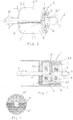
Fig. 1 eine schaubildliche Ansicht einer Magnetkupplung zur Übertragung eines Drehmoments mit einem rückseitig kegelstumpfförmig abgeschrägten Umleitelement; -
Fig. 2 einen Längsschnitt durch eine Magnetkupplung gemäßFig. 1 , wobei die beiden Kupplungsteile durch ein Gehäuse getrennt sind; -
Fig. 3 eine Seitenansicht auf eine Rückseite des antriebsseitigen Kupplungsteils gemäßFig. 1 und Fig. 2 , jedoch ohne Gehäuse; -
Fig. 4 einen Längsschnitt durch eine Variante der Magnetkupplung gemäßFig. 2 mit einem diamagnetischen Abschirmelement an einer Vorderseite des antriebsseitigen Kupplungsteils; -
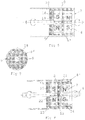
Fig. 5 eine schaubildliche Ansicht einer Variante einer Magnetkupplung zur Übertragung eines Drehmoments mit einem Umleitelement ohne eine rückseitige kegelstumpfförmige Abschrägung des Umleitelements; -
Fig. 6 einen Längsschnitt durch eine Magnetkupplung gemäßFig. 5 , wobei die beiden Kupplungsteile durch ein Gehäuse getrennt sind und mit einem diamagnetischen Abschirmelement an einer Rückseite des antriebsseitigen Kupplungsteils; -
Fig. 7 eine Seitenansicht auf eine Rückseite des antriebsseitigen Kupplungsteils gemäßFig. 5 undFig. 6 ohne Gehäuse; -
Fig. 8 einen Längsschnitt durch eine Magnetkupplung gemäßFig. 5 , wobei das Umleitelement einen Zwischenboden aufweist, welcher an einer Vorderseite des antriebsseitigen Kupplungsteils angeordnet ist und mit einer diamagnetischen Abschirmung an dessen Rückseite; -
Fig. 9 eine Seitenansicht auf eine Rückseite des antriebsseitigen Kupplungsteils gemäßFig. 5 undFig. 8 ohne Gehäuse; -
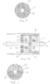
Fig. 10 einen Längsschnitt durch eine Magnetkupplung gemäßFig. 8 , wobei die diamagnetische Abschirmung durch einen ferromagnetischen Boden ersetzt ist; und -
Fig. 11 eine Seitenansicht auf eine Rückseite des antriebsseitigen Kupplungsteils gemäßFig. 5 undFig. 10 ohne Gehäuse. - In
Fig. 1 ist eine Magnetkupplung 1 dargestellt, welche eine Antriebswelle 2 mit einer Abtriebswelle 3 zur berührungslosen Übertragung eines Drehmoments M, M' verbindet. Die beiden Wellen 2, 3 liegen auf einer gemeinsamen Drehachse 4, sodass ein antriebsseitiger Kupplungsteil 5 relativ zu einem abtriebsseitigen Kupplungsteil 6 drehbar gelagert ist. Der abtriebsseitige Kupplungsteil 6 umfasst einen abtriebsseitigen zweipoligen Dauermagnet 7, welcher drehfest mit der Abtriebswelle 3 verbunden ist, insbesondere auf die Abtriebswelle 3 aufgesteckt ist (vgl.Fig. 2 ). Der abtriebsseitige Dauermagnet 7 ist umfangseitig von einem im Wesentlichen topfförmigen Umleitelement 8 mit einem hohlzylinderförmigen Mantel 8' und einem den Mantel 8' an einem Ende abschließenden, scheibenförmigen, im Wesentlichen flachen Boden 8" (vgl.Fig. 2 ) umgeben. Dabei ist zwischen dem abtriebsseitigen Dauermagnet 7 und dem Umleitelement 8 ein Abstand bzw. Spalt vorgesehen, sodass der abtriebsseitige Kupplungsteil 6 berührungslos mit dem antriebsseitigen Kupplungsteil 5 gekoppelt ist. Das Umleitelement 8 besteht größtenteils aus ferromagnetischem Material. Der Mantel 8' des Umleitelements 8 ist lediglich in einem schmalen Winkelbereich durch eine diamagnetische Trennung 9 unterbrochen und die Trennung 9 erstreckt sich außerdem quer über den Boden 8''. Die Trennung 9 teilt das Umleitelement 8 im Wesentlichen in zwei ferromagnetische Hälften bzw. Halbschalen. Eine durch die Trennung 9 verlaufende Schnittebene steht somit senkrecht auf eine Magnetisierungsrichtung des mit dem Umleitelement 8 verbundenen antriebsseitigen zweipoligen Dauermagnets 10 (vgl.Fig. 2 ). Die ferromagnetischen Abschnitte 11, 12 des Umleitelements 8 sind daher entsprechend dem antriebsseitigen Dauermagnet 10 magnetisiert. Im Fall von mehrpoligen Dauermagneten 7, 10 wären entsprechende zusätzliche Trennungen im Umleitelement 8 erforderlich, um eine optimale Magnetisierung des Umleitelements 8 zu ermöglichen. Mit der antriebsseitig kegelstumpfförmigen Abschrägung 13 des Umleitelements 8 wird ein möglichst homogener Magnetfeldgradient im Umleitelement 8 erzielt, bzw. werden etwaige durch Inhomogenitäten an den Kanten hervorgerufene Magnetisierungsverluste reduziert. - In
Fig. 2 ist die inFig. 1 gezeigte Magnetkupplung 1 im Längsschnitt dargestellt, wobei zusätzlich der antriebsseitige Kupplungsteil 5 durch ein Gehäuse 14 vom abtriebsseitigen Kupplungsteil 6 getrennt ist. Das Gehäuse 14 bildet dabei eine hermetische Trennung zwischen den Funktionsbereichen der beiden Kupplungsteile 5, 6. Das antriebsseitige Kupplungsteil 5 mit dem antriebsseitigen Dauermagnet 10 und dem Umleitelement 8 ist drehbar im Gehäuse 14 aufgenommen, wobei das Gehäuse 14 der topfförmigen Ausnehmung im Umleitelement 8 annähernd bis zu einer Vorderseite 15 des antriebsseitigen Dauermagnets 10 folgt und selbst eine entsprechend kleinere topfförmige Ausnehmung 16 zur Aufnahme des abtriebsseitigen Kupplungsteils 6 bildet. Da der Innendurchmesser des Mantels 8' des Umleitelements 8 naturgemäß größer als der Außendurchmesser des darin drehbar angeordneten gegenüberliegenden Kupplungsteils 6 bzw. dessen Dauermagnets 7 ist und zugleich der Dauermagnet 10 des mit dem Umleitelement 8 verbundenen Kupplungsteils 5 den Mantel 8' vorteilhafter Weise radial vollständig ausfüllt, ist dessen Außendurchmesser im Allgemeinen größer als jener des gegenüberliegenden Dauermagnets 7. Durch den Boden 8" des Umleitelements 8 aus ferromagnetischem Material werden etwaige zur Rückseite des Dauermagnets 10 austretende Feldlinien über das Umleitelement 8 zur Vorderseite umgelenkt und tragen somit zur Drehmomentübertragung bei. Wie weiters inFig. 2 ersichtlich, sind die beiden Dauermagnete 7, 10 auf die jeweils zugeordneten Wellen 3, 2 aufgesteckt bzw. entlang der Drehachse 4 von den Wellen 3, 2 durchsetzt. - In
Fig. 3 ist die Magnetkupplung 1 mit Blick auf den Boden 8" des Umleitelements 8 dargestellt, wobei die quer über den Boden 8" verlaufende diamagnetische Trennung 9, welche den Boden 8" in zwei halbkreisförmige Hälften teilt, ersichtlich ist. -
Fig. 4 zeigt eine gegenüberFig. 2 erweiterte Variante der Magnetkupplung 1, wobei die Vorderseite 15 des mit dem Umleitelement 8 verbundenen Dauermagnets 10 mit einem diamagnetischen Abschirmelement 17 versehen ist. Durch das Abschirmelement 17 wird einem Schluss der magnetischen Feldlinien zwischen den beiden Dauermagneten 7, 10 bei geringen Radien, d.h. in der Nähe der Drehachse 4, entgegengewirkt. - Dadurch wird eine Verschiebung der wirkenden Magnetkraft zu größeren Radien, insbesondere zum Umleitelement 8, und somit eine effizientere Drehmomentübertragung erzielt.
- Bei den im Folgenden beschriebenen Varianten der Magnetkupplung 1, welche der in
Fig. 5 gezeigten schaubildlichen Ansicht entsprechen, ist im Unterschied zuFig. 1 konstruktionsbedingt an der Rückseite des Umleitelements 8 keine kegelstumpfförmige Abschrägung vorgesehen. Ansonsten ist der grundsätzliche Aufbau identisch mit der inFig. 1 gezeigten Magnetkupplung 1. - In
Fig. 6 und 7 ist eine Variante der Magnetkupplung 1 gezeigt, bei der der ferromagnetische Boden 8" des Umleitelements 8 (vgl.Fig. 2 und4 ) durch ein diamagnetisches Abschirmelement 18 an der Rückseite 19 des mit dem Umleitelement 8 verbundenen Dauermagnets 10 ersetzt ist. Durch das Abschirmelement 18 werden rückseitig austretende Feldlinien des Magnetfelds zwischen den Dauermagneten 7, 10 der beiden Kupplungsteile 5, 6 vermieden, sodass an der Außen- und Vorderseite ein entsprechend höheres Magnetfeld erzielt wird. Eine Trennung 9 wie beim ferromagnetischen Boden 8" (vgl.Fig. 3 ) ist bei dem Abschirmelement 18 nicht erforderlich. Zur Befestigung des Abschirmelements 18 im Umleitelement 8 weist der Mantel 8' des Umleitelements 8 am geschlossenen Ende eine Verjüngung 20 auf, in welche das Abschirmelement 18 eingepasst ist. Der Mantel 8' umgibt demzufolge sowohl den damit drehfest verbundenen Dauermagnet 10 und den gegenüberliegenden Dauermagnet 7 als auch das Abschirmelement 18. - Eine weitere alternative Ausführungsform der Magnetkupplung 1 ist in
Fig. 8 und9 gezeigt, wobei das Umleitelement 8 hier anstelle des Bodens 8" einen Zwischenboden 21 etwa auf halber Höhe des Mantels 8' aufweist. Der Zwischenboden 21 weist - wie der Boden 8" (vgl.Fig. 3 ) - einen quer durch die Drehachse 4 verlaufenden Trennstreifen 22 auf. Beidseitig des Zwischenbodens 21 bildet das Umleitelement 8 somit topfförmige Ausnehmungen 23, 24 aus, wobei in die antriebsseitige Ausnehmung 23 der antriebsseitige Dauermagnet 10 und im Anschluss daran ein scheibenförmiges diamagnetisches Abschirmelement 25 aufgenommen und drehfest verbunden ist. Die abtriebsseitige Ausnehmung 24 umgibt dementsprechend den abtriebsseitigen Dauermagnet 7. Gegenüber der inFig. 6 gezeigten Variante der Magnetkupplung 1 bietet die Variante gemäßFig. 8 eine bessere Formstabilität des Umleitelements 8 und somit eine höhere mechanische Belastbarkeit der Magnetkupplung 1 im Sinne der Fertigung. - Die in
Fig. 10 und 11 gezeigte Variante der Magnetkupplung 1 entspricht im Wesentlichen der inFig. 8 und9 gezeigten Ausführungsform, wobei lediglich anstelle des diamagnetischen Abschirmelements 25 ein ferromagnetischer Boden 26 vergleichbar dem Boden 8" des Umleitelements 8 gemäßFig. 2 und 3 in die antriebsseitige Ausnehmung 23 eingesetzt ist. Der eingesetzte Boden 26 weist dabei zweckmäßig ebenfalls einen diamagnetischen Trennstreifen 27 auf, welcher den Boden 26 in zwei halbkreisförmige Hälften teilt und so einen Schluss des magnetischen Kreises zwischen den beiden Polen des Dauermagnets 10 über die Rückseite des Kupplungsteils 5 verhindert.
Claims (10)
- Magnetkupplung (1) zur Drehmomentübertragung entlang einer Drehachse (4), mit zwei relativ zueinander drehbaren Kupplungsteilen (5, 6), wobei ein antriebsseitiger Kupplungsteil (5) einen antriebsseitigen Dauermagnet (10) aufweist und ein abtriebsseitiger Kupplungsteil (6) einen dem antriebsseitigen Dauermagnet (10) entlang der Drehachse (4) gegenüberliegenden und im Abstand davon angeordneten abtriebsseitigen Dauermagnet (7) aufweist, wobei einer der Kupplungsteile (5; 6) ein zumindest teilweise ferromagnetisches Umleitelement (8) umfasst, welches mit dem Dauermagnet (10; 7) des Kupplungsteils (5; 6) drehfest verbunden ist, wobei ein Teil des Umleitelements (8) radial außerhalb des gegenüberliegenden Dauermagnets (7; 10) angeordnet ist, dadurch gekennzeichnet, dass das Umleitelement (8) zumindest eine diamagnetische Trennung (9) aufweist, welche das Umleitelement (8) in zumindest zwei ferromagnetische Abschnitte (11, 12) unterteilt.
- Magnetkupplung (1) nach Anspruch 1, dadurch gekennzeichnet, dass die beiden Dauermagnete (10, 7) jeweils 2-, 4-, oder 6-polige Dauermagnete sind.
- Magnetkupplung (1) nach Anspruch 1 oder 2, dadurch gekennzeichnet, dass sich das Umleitelement (8) an eine dem gegenüberliegenden Dauermagnet (7; 10) abgewandten Rückseite (19) des drehfest verbundenen Dauermagnets (10; 7) erstreckt.
- Magnetkupplung (1) nach einem der Ansprüche 1 bis 3, dadurch gekennzeichnet, dass das Umleitelement (8) einen hohlzylinderförmigen Mantel (8') aufweist und vorzugsweise mit einem auf im Wesentlichen halber Höhe des Mantels (8') angeordneten Zwischenboden (21) ausgebildet ist.
- Magnetkupplung (1) nach einem der Ansprüche 1 bis 4, dadurch gekennzeichnet, dass an einer dem gegenüberliegenden Dauermagnet (7) abgewandten Rückseite (19) des drehfest mit dem Umleitelement (8) verbundenen Dauermagnets (10) ein diamagnetisches Abschirmelement (18, 25) angeordnet ist.
- Magnetkupplung (1) nach einem der Ansprüche 1 bis 5, dadurch gekennzeichnet, dass an einer dem gegenüberliegenden Dauermagnet (7) zugewandten Vorderseite (15) des drehfest mit dem Umleitelement (8) verbundenen Dauermagnets (10), insbesondere in einem um die Drehachse (4) zentrierten Bereich, ein diamagnetisches Abschirmelement (17) angeordnet ist, welches vorzugsweise umfangseitig an das Umleitelement (8) anschließt.
- Magnetkupplung (1) nach einem der Ansprüche 1 bis 6, dadurch gekennzeichnet, dass die beiden Kupplungsteilen (5, 6) hermetisch getrennt sind.
- Magnetkupplung (1) nach Anspruch 7, dadurch gekennzeichnet, dass zur hermetischen Trennung der beiden Kupplungsteile zumindest einer der Kupplungsteile (5, 6) in einem im Wesentlichen nichtmagnetischen und nicht elektrisch leitenden Gehäuse (14) untergebracht ist.
- Pumpe mit einem Antrieb und einem Pumpenläufer, wobei der Pumpenläufer über eine Magnetkupplung (1) nach einem der Ansprüche 1 bis 8 mit dem Antrieb verbunden ist.
- Verwendung einer Pumpe nach Anspruch 9 als Medizingerät, insbesondere als implantierte Blutpumpe, vorzugsweise als Herzblutpumpe.
Applications Claiming Priority (2)
| Application Number | Priority Date | Filing Date | Title |
|---|---|---|---|
| ATA50343/2014A AT515555B1 (de) | 2014-05-15 | 2014-05-15 | Magnetkupplung |
| PCT/AT2015/050122 WO2015172173A2 (de) | 2014-05-15 | 2015-05-13 | Magnetkupplung |
Publications (2)
| Publication Number | Publication Date |
|---|---|
| EP3143682A2 EP3143682A2 (de) | 2017-03-22 |
| EP3143682B1 true EP3143682B1 (de) | 2018-01-31 |
Family
ID=53385410
Family Applications (1)
| Application Number | Title | Priority Date | Filing Date |
|---|---|---|---|
| EP15728385.4A Active EP3143682B1 (de) | 2014-05-15 | 2015-05-13 | Magnetkupplung |
Country Status (6)
| Country | Link |
|---|---|
| US (1) | US10704553B2 (de) |
| EP (1) | EP3143682B1 (de) |
| JP (1) | JP6584015B2 (de) |
| AT (1) | AT515555B1 (de) |
| ES (1) | ES2660427T3 (de) |
| WO (1) | WO2015172173A2 (de) |
Families Citing this family (44)
| Publication number | Priority date | Publication date | Assignee | Title |
|---|---|---|---|---|
| US10709827B2 (en) | 2015-10-14 | 2020-07-14 | Technische Universität Wien | Membrane catheter |
| US10905813B2 (en) * | 2015-10-14 | 2021-02-02 | CCORE Technology GmbH | Membrane catheter |
| ITUB20160172A1 (it) * | 2016-02-03 | 2017-08-03 | Ima Spa | Apparato di dosaggio per prodotti in polvere. |
| EP3615102B1 (de) * | 2017-04-28 | 2023-10-25 | Nuheart AS | Intrakorporale vorrichtung zur unterstützung der herzfunktion |
| EP4732889A2 (de) | 2017-06-07 | 2026-04-29 | Supira Medical, Inc. | Vorrichtungen, systeme und verfahren zur bewegung intravaskulärer flüssigkeiten |
| US11511103B2 (en) | 2017-11-13 | 2022-11-29 | Shifamed Holdings, Llc | Intravascular fluid movement devices, systems, and methods of use |
| DE102018201030B4 (de) | 2018-01-24 | 2025-10-16 | Kardion Gmbh | Magnetkuppelelement mit magnetischer Lagerungsfunktion |
| JP7410034B2 (ja) | 2018-02-01 | 2024-01-09 | シファメド・ホールディングス・エルエルシー | 血管内血液ポンプならびに使用および製造の方法 |
| DE102018207575A1 (de) | 2018-05-16 | 2019-11-21 | Kardion Gmbh | Magnetische Stirndreh-Kupplung zur Übertragung von Drehmomenten |
| DE102018207611A1 (de) | 2018-05-16 | 2019-11-21 | Kardion Gmbh | Rotorlagerungssystem |
| DE102018207594A1 (de) | 2018-05-16 | 2019-11-21 | Kardion Gmbh | Rotor, Magnetkupplungsvorrichtung, Elektromotor für ein Herzunterstützungssystem, Pumpeneinheit für ein Herzunterstützungssystem sowie Verfahren zum Herstellen eines Rotors |
| DE102018207622A1 (de) * | 2018-05-16 | 2019-11-21 | Kardion Gmbh | Permanentmagnetische Radialdrehkupplung sowie Mikropumpe mit einer solchen Radialdrehkupplung |
| DE102018208541A1 (de) | 2018-05-30 | 2019-12-05 | Kardion Gmbh | Axialpumpe für ein Herzunterstützungssystem und Verfahren zum Herstellen einer Axialpumpe für ein Herzunterstützungssystem |
| DE102018208549A1 (de) | 2018-05-30 | 2019-12-05 | Kardion Gmbh | Elektronikmodul für ein Herzunterstützungssystem und Verfahren zum Herstellen eines Elektronikmoduls für ein Herzunterstützungssystem |
| DE102018208539A1 (de) | 2018-05-30 | 2019-12-05 | Kardion Gmbh | Motorgehäusemodul zum Abdichten eines Motorraums eines Motors eines Herzunterstützungssystems und Herzunterstützungssystem und Verfahren zum Montieren eines Herzunterstützungssystems |
| DE102018208550A1 (de) | 2018-05-30 | 2019-12-05 | Kardion Gmbh | Leitungsvorrichtung zum Leiten eines Blutstroms für ein Herzunterstützungssystem, Herzunterstützungssystem und Verfahren zum Herstellen einer Leitungsvorrichtung |
| DE102018208538A1 (de) | 2018-05-30 | 2019-12-05 | Kardion Gmbh | Intravasale Blutpumpe und Verfahren zur Herstellung von elektrischen Leiterbahnen |
| DE102018210076A1 (de) | 2018-06-21 | 2019-12-24 | Kardion Gmbh | Verfahren und Vorrichtung zum Erkennen eines Verschleißzustands eines Herzunterstützungssystems, Verfahren und Vorrichtung zum Betreiben eines Herzunterstützungssystems und Herzunterstützungssystem |
| DE102018210058A1 (de) | 2018-06-21 | 2019-12-24 | Kardion Gmbh | Statorschaufelvorrichtung zur Strömungsführung eines aus einer Austrittsöffnung eines Herzunterstützungssystems ausströmenden Fluids, Herzunterstützungssystem mit Statorschaufelvorrichtung, Verfahren zum Betreiben einer Statorschaufelvorrichtung und Herstellverfahren |
| DE102018211297A1 (de) | 2018-07-09 | 2020-01-09 | Kardion Gmbh | Herzunterstützungssystem und Verfahren zur Überwachung der Integrität einer Haltestruktur eines Herzunterstützungssystems |
| DE102018211328A1 (de) | 2018-07-10 | 2020-01-16 | Kardion Gmbh | Laufradgehäuse für ein implantierbares, vaskuläres Unterstützungssystem |
| DE102018211327A1 (de) | 2018-07-10 | 2020-01-16 | Kardion Gmbh | Laufrad für ein implantierbares, vaskuläres Unterstützungssystem |
| DE102018212153A1 (de) | 2018-07-20 | 2020-01-23 | Kardion Gmbh | Zulaufleitung für eine Pumpeneinheit eines Herzunterstützungssystems, Herzunterstützungssystem und Verfahren zum Herstellen einer Zulaufleitung für eine Pumpeneinheit eines Herzunterstützungssystems |
| WO2020028537A1 (en) | 2018-07-31 | 2020-02-06 | Shifamed Holdings, Llc | Intravascaular blood pumps and methods of use |
| AU2019320533B2 (en) | 2018-08-07 | 2024-11-21 | Kardion Gmbh | Bearing device for a cardiac support system, and method for flushing an intermediate space in a bearing device for a cardiac support system |
| WO2020073047A1 (en) | 2018-10-05 | 2020-04-09 | Shifamed Holdings, Llc | Intravascular blood pumps and methods of use |
| WO2021011473A1 (en) | 2019-07-12 | 2021-01-21 | Shifamed Holdings, Llc | Intravascular blood pumps and methods of manufacture and use |
| US11654275B2 (en) | 2019-07-22 | 2023-05-23 | Shifamed Holdings, Llc | Intravascular blood pumps with struts and methods of use and manufacture |
| EP4010046A4 (de) | 2019-08-07 | 2023-08-30 | Calomeni, Michael | Katheterblutpumpen und zusammenklappbare pumpengehäuse |
| EP4034221B1 (de) | 2019-09-25 | 2024-11-13 | Shifamed Holdings, LLC | Katheterblutpumpen und zusammenklappbare pumpengehäuse |
| EP4034192B1 (de) | 2019-09-25 | 2025-12-24 | Supira Medical, Inc. | Intravaskuläre blutpumpensysteme und verfahren zur verwendung und steuerung davon |
| WO2021062260A1 (en) | 2019-09-25 | 2021-04-01 | Shifamed Holdings, Llc | Catheter blood pumps and collapsible blood conduits |
| EP4072650A4 (de) | 2019-12-11 | 2024-01-10 | Shifamed Holdings, LLC | Absteigende aorten- und hohlvenenblutpumpen |
| US12599758B2 (en) | 2019-12-19 | 2026-04-14 | Shifamed Holdings, Llc | Intravascular blood pumps, motors, and fluid control |
| US12029890B2 (en) | 2020-01-21 | 2024-07-09 | Boston Scientific Scimed, Inc. | Magnetic drives having flux enhancers for blood pumps |
| DE102020102474A1 (de) | 2020-01-31 | 2021-08-05 | Kardion Gmbh | Pumpe zum Fördern eines Fluids und Verfahren zum Herstellen einer Pumpe |
| CA3192451A1 (en) | 2020-09-14 | 2022-03-17 | Johannes Bette | Cardiovascular support pump having an impeller with a variable flow area |
| JP2023550938A (ja) | 2020-11-20 | 2023-12-06 | カルディオン ゲーエムベーハー | ガイドワイヤ補助具付き機械的循環支持システム |
| EP4016808A1 (de) * | 2020-12-18 | 2022-06-22 | Accuride International GmbH | Lineares führungssystem |
| KR102276578B1 (ko) | 2020-12-24 | 2021-07-13 | 주식회사 태영팬가드 | 다중 출력구조를 갖는 가변속 동력전달 클러치 시스템 |
| CN117157122A (zh) | 2021-02-10 | 2023-12-01 | 波士顿科学国际有限公司 | 用于血液动力学支持泵的磁性推进器和轴承 |
| GB2607870A (en) * | 2021-06-07 | 2022-12-21 | Magnomatics Ltd | Magnetically geared apparatus and rotor |
| CN118215524A (zh) | 2021-11-16 | 2024-06-18 | 波士顿科学国际有限公司 | 有利于减少溶血的经皮循环支持系统 |
| US12133976B2 (en) | 2021-11-23 | 2024-11-05 | Boston Scientific Scimed, Inc. | Percutaneous circulatory support device facilitating reduced hemolysis class |
Family Cites Families (12)
| Publication number | Priority date | Publication date | Assignee | Title |
|---|---|---|---|---|
| US4065234A (en) * | 1975-12-22 | 1977-12-27 | Nihon Kagaku Kizai Kabushiki Kaisha | Magnetically driven rotary pumps |
| DE3018186A1 (de) * | 1980-05-13 | 1981-11-19 | Thyssen Edelstahlwerke AG, 4000 Düsseldorf | Synchronkupplung |
| JPS63277464A (ja) * | 1987-05-06 | 1988-11-15 | Ishikawajima Harima Heavy Ind Co Ltd | 無段変速装置 |
| JPH05501194A (ja) * | 1989-07-27 | 1993-03-04 | アライド・シグナル・インコーポレーテツド | トルク連結装置 |
| DE19613564C1 (de) * | 1996-04-04 | 1998-01-08 | Guenter Prof Dr Rau | Intravasale Blutpumpe |
| JPH09303254A (ja) * | 1996-05-16 | 1997-11-25 | Mitsubishi Automob Eng Co Ltd | 燃料ポンプ構造 |
| US6863124B2 (en) * | 2001-12-21 | 2005-03-08 | Schlumberger Technology Corporation | Sealed ESP motor system |
| AU2003273612A1 (en) * | 2002-06-11 | 2003-12-22 | Walid Aboul-Hosn | Percutaneously introduced blood pump and related methods |
| WO2008127487A1 (en) * | 2007-01-09 | 2008-10-23 | Magnetic Torque International, Ltd. | Torque transfer system and method of using the same |
| JP2009121676A (ja) * | 2007-10-26 | 2009-06-04 | Denso Corp | 動力伝達装置 |
| EP3248628B1 (de) * | 2010-08-20 | 2019-01-02 | Tc1 Llc | Implantierbare blutpumpe |
| US9362812B2 (en) | 2012-09-18 | 2016-06-07 | Honeywell International Inc. | Shaft coupling apparatus, rotary fluid damper, and deployable device with magnetic coupling mechanism |
-
2014
- 2014-05-15 AT ATA50343/2014A patent/AT515555B1/de active
-
2015
- 2015-05-13 ES ES15728385.4T patent/ES2660427T3/es active Active
- 2015-05-13 EP EP15728385.4A patent/EP3143682B1/de active Active
- 2015-05-13 JP JP2016564123A patent/JP6584015B2/ja active Active
- 2015-05-13 US US15/311,300 patent/US10704553B2/en active Active
- 2015-05-13 WO PCT/AT2015/050122 patent/WO2015172173A2/de not_active Ceased
Also Published As
| Publication number | Publication date |
|---|---|
| WO2015172173A2 (de) | 2015-11-19 |
| WO2015172173A3 (de) | 2015-12-30 |
| US10704553B2 (en) | 2020-07-07 |
| US20170080136A1 (en) | 2017-03-23 |
| AT515555B1 (de) | 2015-10-15 |
| EP3143682A2 (de) | 2017-03-22 |
| ES2660427T3 (es) | 2018-03-22 |
| AT515555A4 (de) | 2015-10-15 |
| JP2017515552A (ja) | 2017-06-15 |
| JP6584015B2 (ja) | 2019-10-02 |
Similar Documents
| Publication | Publication Date | Title |
|---|---|---|
| EP3143682B1 (de) | Magnetkupplung | |
| WO2019219881A1 (de) | Permanentmagnetische radialdrehkupplung | |
| EP0900572B1 (de) | Zentrifugalpumpe | |
| WO2019219874A1 (de) | Permanentmagnetische radialdrehkupplung sowie mikropumpe mit einer solchen radialdrehkupplung | |
| DE102018207608A1 (de) | Permanentmagnetische Radialdrehkupplung | |
| EP3256240A1 (de) | Mischsystem, mischvorrichtung, behälter und verfahren zum mischen eines fluids und/oder eines feststoffs | |
| DE19546336A1 (de) | Magnetkupplung für eine Kreiselpumpe | |
| DE2310927A1 (de) | Befestigungsvorrichtung fuer eingepasste bauteile | |
| DE102018212459B4 (de) | Sensormagnet und motor | |
| EP3469217A1 (de) | Verdichteranordnung | |
| DE1488473A1 (de) | Wechselstromgenerator | |
| EP2730686B1 (de) | Offenend-Spinnrotor | |
| DE1750194A1 (de) | Kreuzgelenkkupplung | |
| DE3620337A1 (de) | Kraftfahrzeug-elektroantrieb | |
| DE4029182C1 (de) | ||
| AT519916B1 (de) | Stoffaustauschvorrichtung | |
| EP0779699B1 (de) | Magnetkupplung für eine Kreiselpumpe | |
| EP3249085A2 (de) | Rotorschaft für einen in einer magnetlageranordnung berührlos gelagerten spinnrotor und spinnrotor | |
| WO2016177462A1 (de) | Magnetkupplung sowie rührvorrichtung mit magnetkupplung | |
| DE102015108625B4 (de) | Magnetisches Getriebe | |
| DE102013110998A1 (de) | Elektromotor in Form eines Außenläufermotors | |
| DE3048071C2 (de) | ||
| DE19715852B4 (de) | Vorrichtung zur Verbindung einer Welle mit einem Gleichlaufgelenk | |
| EP2147620B1 (de) | Überlastkupplung | |
| AT512841B1 (de) | Berührungslose Magnetkupplung |
Legal Events
| Date | Code | Title | Description |
|---|---|---|---|
| STAA | Information on the status of an ep patent application or granted ep patent |
Free format text: STATUS: THE INTERNATIONAL PUBLICATION HAS BEEN MADE |
|
| PUAI | Public reference made under article 153(3) epc to a published international application that has entered the european phase |
Free format text: ORIGINAL CODE: 0009012 |
|
| STAA | Information on the status of an ep patent application or granted ep patent |
Free format text: STATUS: REQUEST FOR EXAMINATION WAS MADE |
|
| 17P | Request for examination filed |
Effective date: 20161215 |
|
| AK | Designated contracting states |
Kind code of ref document: A2 Designated state(s): AL AT BE BG CH CY CZ DE DK EE ES FI FR GB GR HR HU IE IS IT LI LT LU LV MC MK MT NL NO PL PT RO RS SE SI SK SM TR |
|
| AX | Request for extension of the european patent |
Extension state: BA ME |
|
| DAV | Request for validation of the european patent (deleted) | ||
| DAX | Request for extension of the european patent (deleted) | ||
| GRAP | Despatch of communication of intention to grant a patent |
Free format text: ORIGINAL CODE: EPIDOSNIGR1 |
|
| STAA | Information on the status of an ep patent application or granted ep patent |
Free format text: STATUS: GRANT OF PATENT IS INTENDED |
|
| INTG | Intention to grant announced |
Effective date: 20170830 |
|
| GRAS | Grant fee paid |
Free format text: ORIGINAL CODE: EPIDOSNIGR3 |
|
| GRAA | (expected) grant |
Free format text: ORIGINAL CODE: 0009210 |
|
| STAA | Information on the status of an ep patent application or granted ep patent |
Free format text: STATUS: THE PATENT HAS BEEN GRANTED |
|
| AK | Designated contracting states |
Kind code of ref document: B1 Designated state(s): AL AT BE BG CH CY CZ DE DK EE ES FI FR GB GR HR HU IE IS IT LI LT LU LV MC MK MT NL NO PL PT RO RS SE SI SK SM TR |
|
| REG | Reference to a national code |
Ref country code: GB Ref legal event code: FG4D Free format text: NOT ENGLISH Ref country code: CH Ref legal event code: EP |
|
| REG | Reference to a national code |
Ref country code: AT Ref legal event code: REF Ref document number: 968205 Country of ref document: AT Kind code of ref document: T Effective date: 20180215 |
|
| REG | Reference to a national code |
Ref country code: IE Ref legal event code: FG4D Free format text: LANGUAGE OF EP DOCUMENT: GERMAN |
|
| REG | Reference to a national code |
Ref country code: CH Ref legal event code: NV Representative=s name: RENTSCH PARTNER AG, CH |
|
| REG | Reference to a national code |
Ref country code: DE Ref legal event code: R096 Ref document number: 502015003006 Country of ref document: DE |
|
| REG | Reference to a national code |
Ref country code: NL Ref legal event code: FP |
|
| REG | Reference to a national code |
Ref country code: ES Ref legal event code: FG2A Ref document number: 2660427 Country of ref document: ES Kind code of ref document: T3 Effective date: 20180322 |
|
| REG | Reference to a national code |
Ref country code: FR Ref legal event code: PLFP Year of fee payment: 4 |
|
| REG | Reference to a national code |
Ref country code: LT Ref legal event code: MG4D |
|
| PG25 | Lapsed in a contracting state [announced via postgrant information from national office to epo] |
Ref country code: NO Free format text: LAPSE BECAUSE OF FAILURE TO SUBMIT A TRANSLATION OF THE DESCRIPTION OR TO PAY THE FEE WITHIN THE PRESCRIBED TIME-LIMIT Effective date: 20180430 Ref country code: LT Free format text: LAPSE BECAUSE OF FAILURE TO SUBMIT A TRANSLATION OF THE DESCRIPTION OR TO PAY THE FEE WITHIN THE PRESCRIBED TIME-LIMIT Effective date: 20180131 Ref country code: HR Free format text: LAPSE BECAUSE OF FAILURE TO SUBMIT A TRANSLATION OF THE DESCRIPTION OR TO PAY THE FEE WITHIN THE PRESCRIBED TIME-LIMIT Effective date: 20180131 Ref country code: FI Free format text: LAPSE BECAUSE OF FAILURE TO SUBMIT A TRANSLATION OF THE DESCRIPTION OR TO PAY THE FEE WITHIN THE PRESCRIBED TIME-LIMIT Effective date: 20180131 |
|
| PG25 | Lapsed in a contracting state [announced via postgrant information from national office to epo] |
Ref country code: IS Free format text: LAPSE BECAUSE OF FAILURE TO SUBMIT A TRANSLATION OF THE DESCRIPTION OR TO PAY THE FEE WITHIN THE PRESCRIBED TIME-LIMIT Effective date: 20180531 Ref country code: GR Free format text: LAPSE BECAUSE OF FAILURE TO SUBMIT A TRANSLATION OF THE DESCRIPTION OR TO PAY THE FEE WITHIN THE PRESCRIBED TIME-LIMIT Effective date: 20180501 Ref country code: LV Free format text: LAPSE BECAUSE OF FAILURE TO SUBMIT A TRANSLATION OF THE DESCRIPTION OR TO PAY THE FEE WITHIN THE PRESCRIBED TIME-LIMIT Effective date: 20180131 Ref country code: RS Free format text: LAPSE BECAUSE OF FAILURE TO SUBMIT A TRANSLATION OF THE DESCRIPTION OR TO PAY THE FEE WITHIN THE PRESCRIBED TIME-LIMIT Effective date: 20180131 Ref country code: SE Free format text: LAPSE BECAUSE OF FAILURE TO SUBMIT A TRANSLATION OF THE DESCRIPTION OR TO PAY THE FEE WITHIN THE PRESCRIBED TIME-LIMIT Effective date: 20180131 Ref country code: PL Free format text: LAPSE BECAUSE OF FAILURE TO SUBMIT A TRANSLATION OF THE DESCRIPTION OR TO PAY THE FEE WITHIN THE PRESCRIBED TIME-LIMIT Effective date: 20180131 Ref country code: BG Free format text: LAPSE BECAUSE OF FAILURE TO SUBMIT A TRANSLATION OF THE DESCRIPTION OR TO PAY THE FEE WITHIN THE PRESCRIBED TIME-LIMIT Effective date: 20180430 |
|
| PG25 | Lapsed in a contracting state [announced via postgrant information from national office to epo] |
Ref country code: MT Free format text: LAPSE BECAUSE OF FAILURE TO SUBMIT A TRANSLATION OF THE DESCRIPTION OR TO PAY THE FEE WITHIN THE PRESCRIBED TIME-LIMIT Effective date: 20180131 |
|
| PG25 | Lapsed in a contracting state [announced via postgrant information from national office to epo] |
Ref country code: AL Free format text: LAPSE BECAUSE OF FAILURE TO SUBMIT A TRANSLATION OF THE DESCRIPTION OR TO PAY THE FEE WITHIN THE PRESCRIBED TIME-LIMIT Effective date: 20180131 Ref country code: RO Free format text: LAPSE BECAUSE OF FAILURE TO SUBMIT A TRANSLATION OF THE DESCRIPTION OR TO PAY THE FEE WITHIN THE PRESCRIBED TIME-LIMIT Effective date: 20180131 Ref country code: EE Free format text: LAPSE BECAUSE OF FAILURE TO SUBMIT A TRANSLATION OF THE DESCRIPTION OR TO PAY THE FEE WITHIN THE PRESCRIBED TIME-LIMIT Effective date: 20180131 |
|
| REG | Reference to a national code |
Ref country code: DE Ref legal event code: R097 Ref document number: 502015003006 Country of ref document: DE |
|
| PG25 | Lapsed in a contracting state [announced via postgrant information from national office to epo] |
Ref country code: DK Free format text: LAPSE BECAUSE OF FAILURE TO SUBMIT A TRANSLATION OF THE DESCRIPTION OR TO PAY THE FEE WITHIN THE PRESCRIBED TIME-LIMIT Effective date: 20180131 Ref country code: CZ Free format text: LAPSE BECAUSE OF FAILURE TO SUBMIT A TRANSLATION OF THE DESCRIPTION OR TO PAY THE FEE WITHIN THE PRESCRIBED TIME-LIMIT Effective date: 20180131 Ref country code: SM Free format text: LAPSE BECAUSE OF FAILURE TO SUBMIT A TRANSLATION OF THE DESCRIPTION OR TO PAY THE FEE WITHIN THE PRESCRIBED TIME-LIMIT Effective date: 20180131 Ref country code: SK Free format text: LAPSE BECAUSE OF FAILURE TO SUBMIT A TRANSLATION OF THE DESCRIPTION OR TO PAY THE FEE WITHIN THE PRESCRIBED TIME-LIMIT Effective date: 20180131 |
|
| PLBE | No opposition filed within time limit |
Free format text: ORIGINAL CODE: 0009261 |
|
| STAA | Information on the status of an ep patent application or granted ep patent |
Free format text: STATUS: NO OPPOSITION FILED WITHIN TIME LIMIT |
|
| 26N | No opposition filed |
Effective date: 20181102 |
|
| REG | Reference to a national code |
Ref country code: BE Ref legal event code: MM Effective date: 20180531 |
|
| PG25 | Lapsed in a contracting state [announced via postgrant information from national office to epo] |
Ref country code: MC Free format text: LAPSE BECAUSE OF FAILURE TO SUBMIT A TRANSLATION OF THE DESCRIPTION OR TO PAY THE FEE WITHIN THE PRESCRIBED TIME-LIMIT Effective date: 20180131 |
|
| REG | Reference to a national code |
Ref country code: IE Ref legal event code: MM4A |
|
| PG25 | Lapsed in a contracting state [announced via postgrant information from national office to epo] |
Ref country code: SI Free format text: LAPSE BECAUSE OF FAILURE TO SUBMIT A TRANSLATION OF THE DESCRIPTION OR TO PAY THE FEE WITHIN THE PRESCRIBED TIME-LIMIT Effective date: 20180131 |
|
| PG25 | Lapsed in a contracting state [announced via postgrant information from national office to epo] |
Ref country code: LU Free format text: LAPSE BECAUSE OF NON-PAYMENT OF DUE FEES Effective date: 20180513 |
|
| PG25 | Lapsed in a contracting state [announced via postgrant information from national office to epo] |
Ref country code: IE Free format text: LAPSE BECAUSE OF NON-PAYMENT OF DUE FEES Effective date: 20180513 |
|
| PG25 | Lapsed in a contracting state [announced via postgrant information from national office to epo] |
Ref country code: BE Free format text: LAPSE BECAUSE OF NON-PAYMENT OF DUE FEES Effective date: 20180531 |
|
| PG25 | Lapsed in a contracting state [announced via postgrant information from national office to epo] |
Ref country code: TR Free format text: LAPSE BECAUSE OF FAILURE TO SUBMIT A TRANSLATION OF THE DESCRIPTION OR TO PAY THE FEE WITHIN THE PRESCRIBED TIME-LIMIT Effective date: 20180131 |
|
| PG25 | Lapsed in a contracting state [announced via postgrant information from national office to epo] |
Ref country code: PT Free format text: LAPSE BECAUSE OF FAILURE TO SUBMIT A TRANSLATION OF THE DESCRIPTION OR TO PAY THE FEE WITHIN THE PRESCRIBED TIME-LIMIT Effective date: 20180131 |
|
| PG25 | Lapsed in a contracting state [announced via postgrant information from national office to epo] |
Ref country code: CY Free format text: LAPSE BECAUSE OF FAILURE TO SUBMIT A TRANSLATION OF THE DESCRIPTION OR TO PAY THE FEE WITHIN THE PRESCRIBED TIME-LIMIT Effective date: 20180131 Ref country code: MK Free format text: LAPSE BECAUSE OF NON-PAYMENT OF DUE FEES Effective date: 20180131 Ref country code: HU Free format text: LAPSE BECAUSE OF FAILURE TO SUBMIT A TRANSLATION OF THE DESCRIPTION OR TO PAY THE FEE WITHIN THE PRESCRIBED TIME-LIMIT; INVALID AB INITIO Effective date: 20150513 |
|
| REG | Reference to a national code |
Ref country code: AT Ref legal event code: MM01 Ref document number: 968205 Country of ref document: AT Kind code of ref document: T Effective date: 20200513 |
|
| PG25 | Lapsed in a contracting state [announced via postgrant information from national office to epo] |
Ref country code: AT Free format text: LAPSE BECAUSE OF NON-PAYMENT OF DUE FEES Effective date: 20200513 |
|
| P01 | Opt-out of the competence of the unified patent court (upc) registered |
Effective date: 20230630 |
|
| PGFP | Annual fee paid to national office [announced via postgrant information from national office to epo] |
Ref country code: NL Payment date: 20250522 Year of fee payment: 11 |
|
| PGFP | Annual fee paid to national office [announced via postgrant information from national office to epo] |
Ref country code: DE Payment date: 20250519 Year of fee payment: 11 |
|
| PGFP | Annual fee paid to national office [announced via postgrant information from national office to epo] |
Ref country code: GB Payment date: 20250522 Year of fee payment: 11 Ref country code: ES Payment date: 20250616 Year of fee payment: 11 |
|
| PGFP | Annual fee paid to national office [announced via postgrant information from national office to epo] |
Ref country code: IT Payment date: 20250530 Year of fee payment: 11 |
|
| PGFP | Annual fee paid to national office [announced via postgrant information from national office to epo] |
Ref country code: FR Payment date: 20250521 Year of fee payment: 11 |
|
| PGFP | Annual fee paid to national office [announced via postgrant information from national office to epo] |
Ref country code: CH Payment date: 20250601 Year of fee payment: 11 |