EP3143682B1 - Embrayage électromagnétique - Google Patents
Embrayage électromagnétique Download PDFInfo
- Publication number
- EP3143682B1 EP3143682B1 EP15728385.4A EP15728385A EP3143682B1 EP 3143682 B1 EP3143682 B1 EP 3143682B1 EP 15728385 A EP15728385 A EP 15728385A EP 3143682 B1 EP3143682 B1 EP 3143682B1
- Authority
- EP
- European Patent Office
- Prior art keywords
- permanent magnet
- coupling
- magnetic coupling
- diverting element
- magnetic
- Prior art date
- Legal status (The legal status is an assumption and is not a legal conclusion. Google has not performed a legal analysis and makes no representation as to the accuracy of the status listed.)
- Active
Links
Images

Classifications
-
- F—MECHANICAL ENGINEERING; LIGHTING; HEATING; WEAPONS; BLASTING
- F04—POSITIVE - DISPLACEMENT MACHINES FOR LIQUIDS; PUMPS FOR LIQUIDS OR ELASTIC FLUIDS
- F04D—NON-POSITIVE-DISPLACEMENT PUMPS
- F04D13/00—Pumping installations or systems
- F04D13/02—Units comprising pumps and their driving means
- F04D13/06—Units comprising pumps and their driving means the pump being electrically driven
- F04D13/0606—Canned motor pumps
- F04D13/0613—Special connection between the rotor compartments
-
- A—HUMAN NECESSITIES
- A61—MEDICAL OR VETERINARY SCIENCE; HYGIENE
- A61M—DEVICES FOR INTRODUCING MEDIA INTO, OR ONTO, THE BODY; DEVICES FOR TRANSDUCING BODY MEDIA OR FOR TAKING MEDIA FROM THE BODY; DEVICES FOR PRODUCING OR ENDING SLEEP OR STUPOR
- A61M60/00—Blood pumps; Devices for mechanical circulatory actuation; Balloon pumps for circulatory assistance
- A61M60/10—Location thereof with respect to the patient's body
- A61M60/122—Implantable pumps or pumping devices, i.e. the blood being pumped inside the patient's body
-
- A—HUMAN NECESSITIES
- A61—MEDICAL OR VETERINARY SCIENCE; HYGIENE
- A61M—DEVICES FOR INTRODUCING MEDIA INTO, OR ONTO, THE BODY; DEVICES FOR TRANSDUCING BODY MEDIA OR FOR TAKING MEDIA FROM THE BODY; DEVICES FOR PRODUCING OR ENDING SLEEP OR STUPOR
- A61M60/00—Blood pumps; Devices for mechanical circulatory actuation; Balloon pumps for circulatory assistance
- A61M60/20—Type thereof
- A61M60/205—Non-positive displacement blood pumps
-
- A—HUMAN NECESSITIES
- A61—MEDICAL OR VETERINARY SCIENCE; HYGIENE
- A61M—DEVICES FOR INTRODUCING MEDIA INTO, OR ONTO, THE BODY; DEVICES FOR TRANSDUCING BODY MEDIA OR FOR TAKING MEDIA FROM THE BODY; DEVICES FOR PRODUCING OR ENDING SLEEP OR STUPOR
- A61M60/00—Blood pumps; Devices for mechanical circulatory actuation; Balloon pumps for circulatory assistance
- A61M60/40—Details relating to driving
- A61M60/403—Details relating to driving for non-positive displacement blood pumps
- A61M60/419—Details relating to driving for non-positive displacement blood pumps the force acting on the blood contacting member being permanent magnetic, e.g. from a rotating magnetic coupling between driving and driven magnets
-
- A—HUMAN NECESSITIES
- A61—MEDICAL OR VETERINARY SCIENCE; HYGIENE
- A61M—DEVICES FOR INTRODUCING MEDIA INTO, OR ONTO, THE BODY; DEVICES FOR TRANSDUCING BODY MEDIA OR FOR TAKING MEDIA FROM THE BODY; DEVICES FOR PRODUCING OR ENDING SLEEP OR STUPOR
- A61M60/00—Blood pumps; Devices for mechanical circulatory actuation; Balloon pumps for circulatory assistance
- A61M60/80—Constructional details other than related to driving
- A61M60/802—Constructional details other than related to driving of non-positive displacement blood pumps
- A61M60/827—Sealings between moving parts
-
- H—ELECTRICITY
- H02—GENERATION; CONVERSION OR DISTRIBUTION OF ELECTRIC POWER
- H02K—DYNAMO-ELECTRIC MACHINES
- H02K49/00—Dynamo-electric clutches; Dynamo-electric brakes
- H02K49/10—Dynamo-electric clutches; Dynamo-electric brakes of the permanent-magnet type
- H02K49/104—Magnetic couplings consisting of only two coaxial rotary elements, i.e. the driving element and the driven element
- H02K49/108—Magnetic couplings consisting of only two coaxial rotary elements, i.e. the driving element and the driven element with an axial air gap
-
- H—ELECTRICITY
- H02—GENERATION; CONVERSION OR DISTRIBUTION OF ELECTRIC POWER
- H02K—DYNAMO-ELECTRIC MACHINES
- H02K7/00—Arrangements for handling mechanical energy structurally associated with dynamo-electric machines, e.g. structural association with mechanical driving motors or auxiliary dynamo-electric machines
- H02K7/003—Couplings; Details of shafts
-
- F—MECHANICAL ENGINEERING; LIGHTING; HEATING; WEAPONS; BLASTING
- F16—ENGINEERING ELEMENTS AND UNITS; GENERAL MEASURES FOR PRODUCING AND MAINTAINING EFFECTIVE FUNCTIONING OF MACHINES OR INSTALLATIONS; THERMAL INSULATION IN GENERAL
- F16D—COUPLINGS FOR TRANSMITTING ROTATION; CLUTCHES; BRAKES
- F16D27/00—Magnetically- or electrically- actuated clutches; Control or electric circuits therefor
- F16D27/01—Magnetically- or electrically- actuated clutches; Control or electric circuits therefor with permanent magnets
-
- H—ELECTRICITY
- H02—GENERATION; CONVERSION OR DISTRIBUTION OF ELECTRIC POWER
- H02K—DYNAMO-ELECTRIC MACHINES
- H02K5/00—Casings; Enclosures; Supports
- H02K5/04—Casings or enclosures characterised by the shape, form or construction thereof
- H02K5/12—Casings or enclosures characterised by the shape, form or construction thereof specially adapted for operating in liquid or gas
- H02K5/128—Casings or enclosures characterised by the shape, form or construction thereof specially adapted for operating in liquid or gas using air-gap sleeves or air-gap discs
Definitions
- the invention relates to a magnetic coupling for transmitting torque along an axis of rotation, with two relatively rotatable coupling parts, wherein a drive-side coupling part has a drive-side permanent magnet and an output side coupling part has a drive side permanent magnet along the axis of rotation opposite and spaced therefrom disposed output side permanent magnet, wherein one of Clutch parts comprises an at least partially ferromagnetic Umleitelement which is rotatably connected to the permanent magnet of the coupling part, wherein a part of the Umleitelements is arranged radially outside of the opposite permanent magnet.
- the invention relates to a compact magnetic coupling between separate functional areas without housing feedthrough.
- This structure essentially corresponds to the type of magnetic coupling generally known as a front-end rotary coupling.
- Characteristic of this type of coupling are the axially adjacent, often mirror-inverted, permanent magnets of the two coupling parts. As a rule, the two coupling parts are separated by a plane separating surface, which is perpendicular to the axis of rotation.
- a known alternative to this type of coupling is the central rotary coupling, which has two coaxial with each other arranged hollow cylindrical coupling parts.
- the basic structure of both types of coupling for example, the EP 0 039 777 A2 be removed.
- Central swivel couplings have the advantage of better torque transmission, but are difficult and costly to produce with increasing miniaturization due to the necessary thin-walled hollow cylindrical coupling parts and corresponding flat permanent magnets.
- face rotary couplings show a disproportionate deterioration of the torque transmission when the size is reduced, ie with smaller coupling dimensions not only the available magnetized volume but also the radius decisive for the transmitted torque decreases.
- One possible field of application of the magnetic coupling according to the invention, in which small dimensions of the coupling are particularly desirable, is in particular the use as an implanted medical device, in particular as a blood pump, preferably as a cardiac blood pump or as a cardiac catheter pump.
- a blood pump is already out of the EP 0 904 117 B1 known, wherein the magnetic coupling shown there between the drive and the pump rotor is designed in known manner as a front-end rotary coupling.
- the DE 11 2008 002854 T5 shows a power transmission device for transmitting a rotational driving force.
- this power transmission device comprises a roller with a drive-side permanent magnet and an opposite hub with a driven-side permanent magnet.
- the permanent magnets are arranged opposite one another along an axis of rotation about the drive shaft.
- the roller has an outer ring which surrounds the hub radially on the outside and consists of a magnetic material, for example iron.
- the diverting element has at least one diamagnetic separation which divides the diverting element into at least two ferromagnetic sections. With such a separation, a magnetic short circuit in the bypass element can be avoided.
- the diverting element can - like the outer coupling part of a central rotary coupling - pot-shaped or hollow cylinder-shaped and the other one Surrounding the coupling part circumferentially, ie it preferably extends radially outside of both permanent magnets.
- the diverting element may be formed, for example, as a thin-walled hollow cylinder, so that the magnetized volume of the face rotary coupling remains largely the same while at the same time a transferable torque comparable to a central rotary coupling can be achieved between the diverting element and the permanent magnet located at a distance therefrom.
- the magnetization direction of the permanent magnets is preferably aligned perpendicular to the axis of rotation, ie the magnetic poles are in the circumferential direction from south to north and are - at least in a two-pole design - with respect to the axis of rotation diametrically opposite.
- the diverting element radially bundles magnetic field lines emanating from the permanent magnets and additionally strengthens the magnetic force between the coupling parts because of the ferromagnetic material of the diverting element.
- the compression of the magnetic field lines in the ferromagnetic material increases the magnetic force for transmitting the torque.
- the respective number of poles are set for both magnets.
- the permanent magnets each have two semi-cylindrical magnetic poles.
- the separation may be carried out as a diamagnetic separating strip along a plane intersecting the permanent magnet centrally and transverse to the direction of magnetization, i. the separating strip divides the diverting element into two halves.
- the diverting element When the diverting element extends to a rear side of the permanent magnet, which is remote from the permanent magnet, the magnetization of the diverting element and thus the transmittable torque can be additionally increased.
- the diverting element has a hollow cylindrical shell and is preferably formed with a arranged at substantially half the height of the shell intermediate bottom.
- the diverting element has a substantially H-shaped longitudinal section, wherein the intermediate bottom forms the transverse web lying perpendicular to the axis of rotation, so that cup-shaped recesses are formed on both sides of the intermediate bottom.
- a permanent magnet is added and connected in a rotationally fixed manner.
- a particularly high concentration of magnetic field lines in the diverting element can be achieved if a diamagnetic shielding element is arranged on a rear side of the permanent magnet, which is remote from the opposite permanent magnet and is permanently connected to the diverting element. As a result, field lines extending outside the coupling parts can be avoided and associated losses can be reduced.
- a diamagnetic shielding element is arranged on a front side of the permanent magnet facing the front of the non-rotatably connected to the diverting permanent magnet, in particular in an area centered about the axis of rotation, which connects preferably peripherally or radially outside to the diverting ,
- a deflection of the magnetic field can be achieved in regions located radially at a greater distance from the axis of rotation, so that the torque transmitted at a given magnetic force is increased.
- the two coupling parts are hermetically separated.
- a hermetic separation can be achieved, for example, by a hermetic wall between the two coupling parts, which wall should be neither magnetic nor electrically conductive. This must not necessarily be part of a housing of the coupling, but can for example connect to a housing.
- the present magnetic coupling can also be used without hermetic separation, for example for safety clutches, ie for limiting the transmitted torque.
- At least one of the coupling parts is housed in a substantially non-magnetic and electrically non-conductive housing for the hermetic separation of the two coupling parts. With such a housing losses due to a re-magnetization of the housing or induced eddy currents in the housing can be avoided.
- the present magnetic coupling can be used particularly advantageously in a pump with a drive and a pump rotor, wherein the pump rotor is connected via the magnetic coupling to the drive.
- the pump thus obtained can be designed to be particularly compact, at the same time relatively high torque transmitted with a correspondingly advantageous pump power.
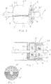
- a magnetic coupling 1 is shown, which connects a drive shaft 2 with an output shaft 3 for non-contact transmission of torque M, M '.
- the two waves 2, 3 lie on a common axis of rotation 4, so that a drive-side coupling part 5 is rotatably mounted relative to a driven-side coupling part 6.
- the output-side coupling part 6 comprises a driven-side two-pole permanent magnet 7, which is rotatably connected to the output shaft 3, in particular to the output shaft 3 is attached (see. Fig. 2 ).
- the driven-side permanent magnet 7 is circumferentially of a substantially cup-shaped Umleitelement 8 with a hollow cylindrical shell 8 'and the shell 8' at one end final, disc-shaped, substantially flat bottom 8 "(see.
- Fig. 2 surround.
- a distance or gap is provided between the output-side permanent magnet 7 and the diverting element 8, so that the output-side coupling part 6 is coupled without contact with the drive-side coupling part 5.
- the diverting element 8 consists largely of ferromagnetic material.
- the jacket 8 'of the diverting element 8 is interrupted only in a narrow angular range by a diamagnetic separation 9 and the separation 9 also extends across the bottom 8''.
- the separation 9 divides the diverting element 8 essentially into two ferromagnetic halves or half shells. A cutting plane running through the separation 9 is thus perpendicular to a magnetization direction of the drive-side two-pole permanent magnet 10 connected to the bypass element 8 (cf. Fig. 2 ).
- the ferromagnetic portions 11, 12 of the bypass 8 are therefore magnetized according to the drive-side permanent magnet 10.
- the drive-side frusto-conical bevel 13 of the diverting element 8 With the drive-side frusto-conical bevel 13 of the diverting element 8, a magnetic field gradient which is as homogeneous as possible is achieved in the diverting element 8, or any magnetization losses caused by inhomogeneities at the edges are reduced.
- Fig. 2 is the in Fig. 1 shown magnetic coupling 1 shown in longitudinal section, wherein additionally the drive side Coupling part 5 is separated by a housing 14 from the output side coupling part 6.
- the housing 14 forms a hermetic separation between the functional areas of the two coupling parts 5, 6.
- the drive-side coupling part 5 with the drive-side permanent magnet 10 and the Umleitelement 8 is rotatably received in the housing 14, the housing 14 of the cup-shaped recess in the diverter 8 approximately to a front side 15 of the drive-side permanent magnet 10 follows and even a correspondingly smaller cup-shaped recess 16 for receiving the driven-side coupling part 6 forms.
- the jacket 8'of the diverting 8 advantageously radially completely fills Through the bottom 8 "of the redirecting element 8 of ferromagnetic material, any field lines emerging to the back of the permanent magnet 10 are deflected via the diverting element 8 to the front side and thus contribute to the transmission of torque in Fig. 2 can be seen, the two permanent magnets 7, 10 attached to the respectively associated shafts 3, 2 or along the axis of rotation 4 of the shafts 3, 2 passes.
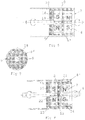
- FIG. 3 the magnetic coupling 1 is shown with respect to the bottom 8 "of the diverting element 8, the diamagnetic separation 9 extending across the bottom 8" dividing the bottom 8 "into two semicircular halves.
- Fig. 4 shows one opposite Fig. 2 extended variant of the magnetic coupling 1, wherein the front side 15 of the associated with the diverting 8 permanent magnet 10 is provided with a diamagnetic shield 17.
- the shielding 17 is a conclusion of the magnetic field lines between the two permanent magnets 7, 10 counteracted at low radii, ie in the vicinity of the axis of rotation 4.
- FIG. 6 and 7 a variant of the magnetic coupling 1 is shown, in which the ferromagnetic bottom 8 "of the diverting 8 (see. Fig. 2 and 4 ) is replaced by a diamagnetic shielding element 18 on the rear side 19 of the permanent magnet 10 connected to the diverting element 8.
- the shielding element 18 back exiting field lines of the magnetic field between the permanent magnets 7, 10 of the two coupling parts 5, 6 are avoided, so that at the outside and front, a correspondingly higher magnetic field is achieved.
- a separation 9 as in the ferromagnetic floor 8 "(see. Fig. 3 ) is not required in the shielding element 18.
- the jacket 8 'of the diverting element 8 has a taper 20 at the closed end, into which the shielding element 18 is fitted.
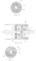
- FIG Fig. 8 and 9 Another alternative embodiment of the magnetic coupling 1 is shown in FIG Fig. 8 and 9
- the diverting element 8 here has, instead of the base 8 ", an intermediate bottom 21 approximately halfway up the jacket 8 '.
- the intermediate bottom 21 has - like the bottom 8" (cf. Fig. 3 ) - a transverse to the axis of rotation 4 extending separating strip 22.
- the diverting element 8 thus forms cup-shaped recesses 23, 24, wherein in the drive-side recess 23 of the drive-side permanent magnet 10 and subsequently thereto disc-shaped diamagnetic shielding member 25 is received and rotatably connected.
- the output side recess 24 accordingly surrounds the output side permanent magnet 7.
- the in Fig. 6 shown variant of the magnetic coupling 1 offers the variant according to Fig. 8 a better dimensional stability of the Umleitelements 8 and thus a higher mechanical strength of the magnetic coupling 1 in terms of manufacturing.
- a ferromagnetic bottom 26 comparable to the bottom 8 "of the diverting 8 according to FIGS. 2 and 3 is inserted into the drive-side recess 23.
- the inserted base 26 expediently also has a diamagnetic separating strip 27, which divides the bottom 26 into two semicircular halves and thus prevents a closure of the magnetic circuit between the two poles of the permanent magnet 10 via the rear side of the coupling part 5.
Landscapes
- Health & Medical Sciences (AREA)
- Engineering & Computer Science (AREA)
- Heart & Thoracic Surgery (AREA)
- Mechanical Engineering (AREA)
- Biomedical Technology (AREA)
- Cardiology (AREA)
- Anesthesiology (AREA)
- Hematology (AREA)
- Life Sciences & Earth Sciences (AREA)
- Animal Behavior & Ethology (AREA)
- General Health & Medical Sciences (AREA)
- Public Health (AREA)
- Veterinary Medicine (AREA)
- Power Engineering (AREA)
- General Engineering & Computer Science (AREA)
- Dynamo-Electric Clutches, Dynamo-Electric Brakes (AREA)
- External Artificial Organs (AREA)
Claims (10)
- Embrayage magnétique (1) pour la transmission d'un couple le long d'un axe de rotation (4), avec deux parties d'embrayage (5, 6) tournant l'une par rapport à l'autre, une partie d'embrayage côté entrée (5) comprenant un aimant permanent côté entrée (10) et une partie d'embrayage côté sortie (6) comprenant un aimant permanent côté sortie (7), qui fait face à l'aimant permanent (10) le long de l'axe de rotation (4) et disposé à une certaine distance de celui-ci, une des parties d'embrayage (5 ; 6) comprenant au moins un élément de renvoi (8) au moins partiellement ferromagnétique, qui est relié de manière solidaire en rotation avec l'aiment permanent (10 ; 7) de la partie d'embrayage (5 ; 6), une partie de l'élément de renvoi (8) étant disposée radialement à l'extérieur de l'aimant permanent opposé (7 ; 10), caractérisé en ce que l'élément de renvoi (8) comprend au moins une séparation diamagnétique (9) qui divise l'élément de renvoi (8) en au moins deux portions ferromagnétiques (11, 12).
- Embrayage magnétique (1) selon la revendication 1, caractérisé en ce que les deux aimants permanents (10, 7) sont chacun des aimants permanents à 2, 4 ou 6 pôles.
- Embrayage magnétique (1) selon la revendication 1 ou 2, caractérisé en ce que l'élément de renvoi (8) s'étend sur un côté arrière (19), opposé à l'aimant permanent opposé (7 ; 10), de l'aimant permanent relié de manière solidaire en rotation (10 ; 7).
- Embrayage magnétique (1) selon l'une des revendications 1 à 3, caractérisé en ce que l'élément de renvoi (8) comprend une enveloppe de forme cylindrique creuse (8') et de préférence est réalisé avec un fond intermédiaire (21) disposé globalement à mi-hauteur de l'enveloppe (8').
- Embrayage magnétique (1) selon l'une des revendications 1 à 4, caractérisé en ce que, sur un côté arrière (19), opposé à l'aimant permanent opposé (7), de l'aimant permanent (10) relié de manière solidaire en rotation avec l'élément de renvoi, est disposé un élément de blindage diamagnétique (18, 25).
- Embrayage magnétique (1) selon l'une des revendications 1 à 5, caractérisé en ce que, sur un côté avant (15), orienté vers l'aimant permanent opposé (7), de l'aimant permanent (10) relié de manière solidaire en rotation avec l'élément de renvoi (8), plus particulièrement dans une zone centrée autour de l'axe de rotation (4), un élément de blindage diamagnétique (17), qui se raccorde, de préférence sur la circonférence, à l'élément de renvoi (8).
- Embrayage magnétique (1) selon l'une des revendications 1 à 6, caractérisé en ce que les deux parties de l'embrayage (5, 6) sont séparées de manière hermétique.
- Embrayage magnétique (1) selon la revendication 7, caractérisé en ce que, pour la séparation hermétique des deux parties de l'embrayage, au moins une des parties de l'embrayage (5, 6) est logée dans un boîtier (14) globalement non magnétique et non électro-conducteur.
- Pompe avec un dispositif d'entraînement et un rotor de pompe, le rotor de pompe étant relié avec le dispositif d'entraînement par l'intermédiaire d'un embrayage magnétique (1) selon l'une des revendications 1 à 8.
- Utilisation d'une pompe selon la revendication 9 en tant qu'appareil médical, plus particulièrement en tant que pompe à sang implantée, de préférence en tant que pompe à sang cardiaque.
Applications Claiming Priority (2)
| Application Number | Priority Date | Filing Date | Title |
|---|---|---|---|
| ATA50343/2014A AT515555B1 (de) | 2014-05-15 | 2014-05-15 | Magnetkupplung |
| PCT/AT2015/050122 WO2015172173A2 (fr) | 2014-05-15 | 2015-05-13 | Embrayage électromagnétique |
Publications (2)
| Publication Number | Publication Date |
|---|---|
| EP3143682A2 EP3143682A2 (fr) | 2017-03-22 |
| EP3143682B1 true EP3143682B1 (fr) | 2018-01-31 |
Family
ID=53385410
Family Applications (1)
| Application Number | Title | Priority Date | Filing Date |
|---|---|---|---|
| EP15728385.4A Active EP3143682B1 (fr) | 2014-05-15 | 2015-05-13 | Embrayage électromagnétique |
Country Status (6)
| Country | Link |
|---|---|
| US (1) | US10704553B2 (fr) |
| EP (1) | EP3143682B1 (fr) |
| JP (1) | JP6584015B2 (fr) |
| AT (1) | AT515555B1 (fr) |
| ES (1) | ES2660427T3 (fr) |
| WO (1) | WO2015172173A2 (fr) |
Families Citing this family (44)
| Publication number | Priority date | Publication date | Assignee | Title |
|---|---|---|---|---|
| US10709827B2 (en) | 2015-10-14 | 2020-07-14 | Technische Universität Wien | Membrane catheter |
| US10905813B2 (en) * | 2015-10-14 | 2021-02-02 | CCORE Technology GmbH | Membrane catheter |
| ITUB20160172A1 (it) * | 2016-02-03 | 2017-08-03 | Ima Spa | Apparato di dosaggio per prodotti in polvere. |
| EP3615102B1 (fr) * | 2017-04-28 | 2023-10-25 | Nuheart AS | Dispositif intracorporel pour soutenir la fonction cardiaque |
| EP4732889A2 (fr) | 2017-06-07 | 2026-04-29 | Supira Medical, Inc. | Dispositifs de déplacement de fluide intravasculaire, systèmes et procédés d'utilisation |
| US11511103B2 (en) | 2017-11-13 | 2022-11-29 | Shifamed Holdings, Llc | Intravascular fluid movement devices, systems, and methods of use |
| DE102018201030B4 (de) | 2018-01-24 | 2025-10-16 | Kardion Gmbh | Magnetkuppelelement mit magnetischer Lagerungsfunktion |
| JP7410034B2 (ja) | 2018-02-01 | 2024-01-09 | シファメド・ホールディングス・エルエルシー | 血管内血液ポンプならびに使用および製造の方法 |
| DE102018207575A1 (de) | 2018-05-16 | 2019-11-21 | Kardion Gmbh | Magnetische Stirndreh-Kupplung zur Übertragung von Drehmomenten |
| DE102018207611A1 (de) | 2018-05-16 | 2019-11-21 | Kardion Gmbh | Rotorlagerungssystem |
| DE102018207594A1 (de) | 2018-05-16 | 2019-11-21 | Kardion Gmbh | Rotor, Magnetkupplungsvorrichtung, Elektromotor für ein Herzunterstützungssystem, Pumpeneinheit für ein Herzunterstützungssystem sowie Verfahren zum Herstellen eines Rotors |
| DE102018207622A1 (de) * | 2018-05-16 | 2019-11-21 | Kardion Gmbh | Permanentmagnetische Radialdrehkupplung sowie Mikropumpe mit einer solchen Radialdrehkupplung |
| DE102018208541A1 (de) | 2018-05-30 | 2019-12-05 | Kardion Gmbh | Axialpumpe für ein Herzunterstützungssystem und Verfahren zum Herstellen einer Axialpumpe für ein Herzunterstützungssystem |
| DE102018208549A1 (de) | 2018-05-30 | 2019-12-05 | Kardion Gmbh | Elektronikmodul für ein Herzunterstützungssystem und Verfahren zum Herstellen eines Elektronikmoduls für ein Herzunterstützungssystem |
| DE102018208539A1 (de) | 2018-05-30 | 2019-12-05 | Kardion Gmbh | Motorgehäusemodul zum Abdichten eines Motorraums eines Motors eines Herzunterstützungssystems und Herzunterstützungssystem und Verfahren zum Montieren eines Herzunterstützungssystems |
| DE102018208550A1 (de) | 2018-05-30 | 2019-12-05 | Kardion Gmbh | Leitungsvorrichtung zum Leiten eines Blutstroms für ein Herzunterstützungssystem, Herzunterstützungssystem und Verfahren zum Herstellen einer Leitungsvorrichtung |
| DE102018208538A1 (de) | 2018-05-30 | 2019-12-05 | Kardion Gmbh | Intravasale Blutpumpe und Verfahren zur Herstellung von elektrischen Leiterbahnen |
| DE102018210076A1 (de) | 2018-06-21 | 2019-12-24 | Kardion Gmbh | Verfahren und Vorrichtung zum Erkennen eines Verschleißzustands eines Herzunterstützungssystems, Verfahren und Vorrichtung zum Betreiben eines Herzunterstützungssystems und Herzunterstützungssystem |
| DE102018210058A1 (de) | 2018-06-21 | 2019-12-24 | Kardion Gmbh | Statorschaufelvorrichtung zur Strömungsführung eines aus einer Austrittsöffnung eines Herzunterstützungssystems ausströmenden Fluids, Herzunterstützungssystem mit Statorschaufelvorrichtung, Verfahren zum Betreiben einer Statorschaufelvorrichtung und Herstellverfahren |
| DE102018211297A1 (de) | 2018-07-09 | 2020-01-09 | Kardion Gmbh | Herzunterstützungssystem und Verfahren zur Überwachung der Integrität einer Haltestruktur eines Herzunterstützungssystems |
| DE102018211328A1 (de) | 2018-07-10 | 2020-01-16 | Kardion Gmbh | Laufradgehäuse für ein implantierbares, vaskuläres Unterstützungssystem |
| DE102018211327A1 (de) | 2018-07-10 | 2020-01-16 | Kardion Gmbh | Laufrad für ein implantierbares, vaskuläres Unterstützungssystem |
| DE102018212153A1 (de) | 2018-07-20 | 2020-01-23 | Kardion Gmbh | Zulaufleitung für eine Pumpeneinheit eines Herzunterstützungssystems, Herzunterstützungssystem und Verfahren zum Herstellen einer Zulaufleitung für eine Pumpeneinheit eines Herzunterstützungssystems |
| WO2020028537A1 (fr) | 2018-07-31 | 2020-02-06 | Shifamed Holdings, Llc | Pompes sanguines intravasculaires et procédés d'utilisation |
| AU2019320533B2 (en) | 2018-08-07 | 2024-11-21 | Kardion Gmbh | Bearing device for a cardiac support system, and method for flushing an intermediate space in a bearing device for a cardiac support system |
| WO2020073047A1 (fr) | 2018-10-05 | 2020-04-09 | Shifamed Holdings, Llc | Pompes à sang intravasculaires et procédés d'utilisation |
| WO2021011473A1 (fr) | 2019-07-12 | 2021-01-21 | Shifamed Holdings, Llc | Pompes à sang intravasculaires et méthode d'utilisation et procédé de fabrication |
| US11654275B2 (en) | 2019-07-22 | 2023-05-23 | Shifamed Holdings, Llc | Intravascular blood pumps with struts and methods of use and manufacture |
| EP4010046A4 (fr) | 2019-08-07 | 2023-08-30 | Calomeni, Michael | Pompes sanguines à cathéter et boîtiers de pompe pliants |
| EP4034221B1 (fr) | 2019-09-25 | 2024-11-13 | Shifamed Holdings, LLC | Pompes à sang de cathéter et boîtiers de pompe pliables |
| EP4034192B1 (fr) | 2019-09-25 | 2025-12-24 | Supira Medical, Inc. | Dispositifs et systèmes de pompes à sang intravasculaires et leurs procédés d'utilisation et de commande |
| WO2021062260A1 (fr) | 2019-09-25 | 2021-04-01 | Shifamed Holdings, Llc | Pompes à sang de cathéter et conduits sanguins pliables |
| EP4072650A4 (fr) | 2019-12-11 | 2024-01-10 | Shifamed Holdings, LLC | Pompes à sang d'aorte descendante et de veine cave |
| US12599758B2 (en) | 2019-12-19 | 2026-04-14 | Shifamed Holdings, Llc | Intravascular blood pumps, motors, and fluid control |
| US12029890B2 (en) | 2020-01-21 | 2024-07-09 | Boston Scientific Scimed, Inc. | Magnetic drives having flux enhancers for blood pumps |
| DE102020102474A1 (de) | 2020-01-31 | 2021-08-05 | Kardion Gmbh | Pumpe zum Fördern eines Fluids und Verfahren zum Herstellen einer Pumpe |
| CA3192451A1 (fr) | 2020-09-14 | 2022-03-17 | Johannes Bette | Pompe de support cardiovasculaire dotee d'un impulseur a zone d'ecoulement variable |
| JP2023550938A (ja) | 2020-11-20 | 2023-12-06 | カルディオン ゲーエムベーハー | ガイドワイヤ補助具付き機械的循環支持システム |
| EP4016808A1 (fr) * | 2020-12-18 | 2022-06-22 | Accuride International GmbH | Système de guidage linéaire |
| KR102276578B1 (ko) | 2020-12-24 | 2021-07-13 | 주식회사 태영팬가드 | 다중 출력구조를 갖는 가변속 동력전달 클러치 시스템 |
| CN117157122A (zh) | 2021-02-10 | 2023-12-01 | 波士顿科学国际有限公司 | 用于血液动力学支持泵的磁性推进器和轴承 |
| GB2607870A (en) * | 2021-06-07 | 2022-12-21 | Magnomatics Ltd | Magnetically geared apparatus and rotor |
| CN118215524A (zh) | 2021-11-16 | 2024-06-18 | 波士顿科学国际有限公司 | 有利于减少溶血的经皮循环支持系统 |
| US12133976B2 (en) | 2021-11-23 | 2024-11-05 | Boston Scientific Scimed, Inc. | Percutaneous circulatory support device facilitating reduced hemolysis class |
Family Cites Families (12)
| Publication number | Priority date | Publication date | Assignee | Title |
|---|---|---|---|---|
| US4065234A (en) * | 1975-12-22 | 1977-12-27 | Nihon Kagaku Kizai Kabushiki Kaisha | Magnetically driven rotary pumps |
| DE3018186A1 (de) * | 1980-05-13 | 1981-11-19 | Thyssen Edelstahlwerke AG, 4000 Düsseldorf | Synchronkupplung |
| JPS63277464A (ja) * | 1987-05-06 | 1988-11-15 | Ishikawajima Harima Heavy Ind Co Ltd | 無段変速装置 |
| JPH05501194A (ja) * | 1989-07-27 | 1993-03-04 | アライド・シグナル・インコーポレーテツド | トルク連結装置 |
| DE19613564C1 (de) * | 1996-04-04 | 1998-01-08 | Guenter Prof Dr Rau | Intravasale Blutpumpe |
| JPH09303254A (ja) * | 1996-05-16 | 1997-11-25 | Mitsubishi Automob Eng Co Ltd | 燃料ポンプ構造 |
| US6863124B2 (en) * | 2001-12-21 | 2005-03-08 | Schlumberger Technology Corporation | Sealed ESP motor system |
| AU2003273612A1 (en) * | 2002-06-11 | 2003-12-22 | Walid Aboul-Hosn | Percutaneously introduced blood pump and related methods |
| WO2008127487A1 (fr) * | 2007-01-09 | 2008-10-23 | Magnetic Torque International, Ltd. | Système de transfert de couple et son procédé d'utilisation |
| JP2009121676A (ja) * | 2007-10-26 | 2009-06-04 | Denso Corp | 動力伝達装置 |
| EP3248628B1 (fr) * | 2010-08-20 | 2019-01-02 | Tc1 Llc | Pompe sanguine implantable |
| US9362812B2 (en) | 2012-09-18 | 2016-06-07 | Honeywell International Inc. | Shaft coupling apparatus, rotary fluid damper, and deployable device with magnetic coupling mechanism |
-
2014
- 2014-05-15 AT ATA50343/2014A patent/AT515555B1/de active
-
2015
- 2015-05-13 ES ES15728385.4T patent/ES2660427T3/es active Active
- 2015-05-13 EP EP15728385.4A patent/EP3143682B1/fr active Active
- 2015-05-13 JP JP2016564123A patent/JP6584015B2/ja active Active
- 2015-05-13 US US15/311,300 patent/US10704553B2/en active Active
- 2015-05-13 WO PCT/AT2015/050122 patent/WO2015172173A2/fr not_active Ceased
Also Published As
| Publication number | Publication date |
|---|---|
| WO2015172173A2 (fr) | 2015-11-19 |
| WO2015172173A3 (fr) | 2015-12-30 |
| US10704553B2 (en) | 2020-07-07 |
| US20170080136A1 (en) | 2017-03-23 |
| AT515555B1 (de) | 2015-10-15 |
| EP3143682A2 (fr) | 2017-03-22 |
| ES2660427T3 (es) | 2018-03-22 |
| AT515555A4 (de) | 2015-10-15 |
| JP2017515552A (ja) | 2017-06-15 |
| JP6584015B2 (ja) | 2019-10-02 |
Similar Documents
| Publication | Publication Date | Title |
|---|---|---|
| EP3143682B1 (fr) | Embrayage électromagnétique | |
| WO2019219881A1 (fr) | Accouplement rotatif radial à aimants permanents | |
| EP0900572B1 (fr) | Pompe centrifuge | |
| WO2019219874A1 (fr) | Joint tournant radial à aimants permanents ainsi que micropompe munie d'un joint tournant radial de ce genre | |
| DE102018207608A1 (de) | Permanentmagnetische Radialdrehkupplung | |
| EP3256240A1 (fr) | Système de mélange, dispositif de mélange, récipient et procédé de melange d'un fluide et/ou d'une matière solide | |
| DE19546336A1 (de) | Magnetkupplung für eine Kreiselpumpe | |
| DE2310927A1 (de) | Befestigungsvorrichtung fuer eingepasste bauteile | |
| DE102018212459B4 (de) | Sensormagnet und motor | |
| EP3469217A1 (fr) | Ensemble de compresseurs | |
| DE1488473A1 (de) | Wechselstromgenerator | |
| EP2730686B1 (fr) | Rotor de filage à extrémité ouverte | |
| DE1750194A1 (de) | Kreuzgelenkkupplung | |
| DE3620337A1 (de) | Kraftfahrzeug-elektroantrieb | |
| DE4029182C1 (fr) | ||
| AT519916B1 (de) | Stoffaustauschvorrichtung | |
| EP0779699B1 (fr) | Accouplement magnétique pour une pompe centrifuge | |
| EP3249085A2 (fr) | Arbre de rotor pour un rotor de filage monté sans contact dans un système de paliers magnétiques et rotor de filage | |
| WO2016177462A1 (fr) | Accouplement magnétique et dispositif d'agitation comprenant un accouplement magnétique | |
| DE102015108625B4 (de) | Magnetisches Getriebe | |
| DE102013110998A1 (de) | Elektromotor in Form eines Außenläufermotors | |
| DE3048071C2 (fr) | ||
| DE19715852B4 (de) | Vorrichtung zur Verbindung einer Welle mit einem Gleichlaufgelenk | |
| EP2147620B1 (fr) | Couple anti-surcharge | |
| AT512841B1 (de) | Berührungslose Magnetkupplung |
Legal Events
| Date | Code | Title | Description |
|---|---|---|---|
| STAA | Information on the status of an ep patent application or granted ep patent |
Free format text: STATUS: THE INTERNATIONAL PUBLICATION HAS BEEN MADE |
|
| PUAI | Public reference made under article 153(3) epc to a published international application that has entered the european phase |
Free format text: ORIGINAL CODE: 0009012 |
|
| STAA | Information on the status of an ep patent application or granted ep patent |
Free format text: STATUS: REQUEST FOR EXAMINATION WAS MADE |
|
| 17P | Request for examination filed |
Effective date: 20161215 |
|
| AK | Designated contracting states |
Kind code of ref document: A2 Designated state(s): AL AT BE BG CH CY CZ DE DK EE ES FI FR GB GR HR HU IE IS IT LI LT LU LV MC MK MT NL NO PL PT RO RS SE SI SK SM TR |
|
| AX | Request for extension of the european patent |
Extension state: BA ME |
|
| DAV | Request for validation of the european patent (deleted) | ||
| DAX | Request for extension of the european patent (deleted) | ||
| GRAP | Despatch of communication of intention to grant a patent |
Free format text: ORIGINAL CODE: EPIDOSNIGR1 |
|
| STAA | Information on the status of an ep patent application or granted ep patent |
Free format text: STATUS: GRANT OF PATENT IS INTENDED |
|
| INTG | Intention to grant announced |
Effective date: 20170830 |
|
| GRAS | Grant fee paid |
Free format text: ORIGINAL CODE: EPIDOSNIGR3 |
|
| GRAA | (expected) grant |
Free format text: ORIGINAL CODE: 0009210 |
|
| STAA | Information on the status of an ep patent application or granted ep patent |
Free format text: STATUS: THE PATENT HAS BEEN GRANTED |
|
| AK | Designated contracting states |
Kind code of ref document: B1 Designated state(s): AL AT BE BG CH CY CZ DE DK EE ES FI FR GB GR HR HU IE IS IT LI LT LU LV MC MK MT NL NO PL PT RO RS SE SI SK SM TR |
|
| REG | Reference to a national code |
Ref country code: GB Ref legal event code: FG4D Free format text: NOT ENGLISH Ref country code: CH Ref legal event code: EP |
|
| REG | Reference to a national code |
Ref country code: AT Ref legal event code: REF Ref document number: 968205 Country of ref document: AT Kind code of ref document: T Effective date: 20180215 |
|
| REG | Reference to a national code |
Ref country code: IE Ref legal event code: FG4D Free format text: LANGUAGE OF EP DOCUMENT: GERMAN |
|
| REG | Reference to a national code |
Ref country code: CH Ref legal event code: NV Representative=s name: RENTSCH PARTNER AG, CH |
|
| REG | Reference to a national code |
Ref country code: DE Ref legal event code: R096 Ref document number: 502015003006 Country of ref document: DE |
|
| REG | Reference to a national code |
Ref country code: NL Ref legal event code: FP |
|
| REG | Reference to a national code |
Ref country code: ES Ref legal event code: FG2A Ref document number: 2660427 Country of ref document: ES Kind code of ref document: T3 Effective date: 20180322 |
|
| REG | Reference to a national code |
Ref country code: FR Ref legal event code: PLFP Year of fee payment: 4 |
|
| REG | Reference to a national code |
Ref country code: LT Ref legal event code: MG4D |
|
| PG25 | Lapsed in a contracting state [announced via postgrant information from national office to epo] |
Ref country code: NO Free format text: LAPSE BECAUSE OF FAILURE TO SUBMIT A TRANSLATION OF THE DESCRIPTION OR TO PAY THE FEE WITHIN THE PRESCRIBED TIME-LIMIT Effective date: 20180430 Ref country code: LT Free format text: LAPSE BECAUSE OF FAILURE TO SUBMIT A TRANSLATION OF THE DESCRIPTION OR TO PAY THE FEE WITHIN THE PRESCRIBED TIME-LIMIT Effective date: 20180131 Ref country code: HR Free format text: LAPSE BECAUSE OF FAILURE TO SUBMIT A TRANSLATION OF THE DESCRIPTION OR TO PAY THE FEE WITHIN THE PRESCRIBED TIME-LIMIT Effective date: 20180131 Ref country code: FI Free format text: LAPSE BECAUSE OF FAILURE TO SUBMIT A TRANSLATION OF THE DESCRIPTION OR TO PAY THE FEE WITHIN THE PRESCRIBED TIME-LIMIT Effective date: 20180131 |
|
| PG25 | Lapsed in a contracting state [announced via postgrant information from national office to epo] |
Ref country code: IS Free format text: LAPSE BECAUSE OF FAILURE TO SUBMIT A TRANSLATION OF THE DESCRIPTION OR TO PAY THE FEE WITHIN THE PRESCRIBED TIME-LIMIT Effective date: 20180531 Ref country code: GR Free format text: LAPSE BECAUSE OF FAILURE TO SUBMIT A TRANSLATION OF THE DESCRIPTION OR TO PAY THE FEE WITHIN THE PRESCRIBED TIME-LIMIT Effective date: 20180501 Ref country code: LV Free format text: LAPSE BECAUSE OF FAILURE TO SUBMIT A TRANSLATION OF THE DESCRIPTION OR TO PAY THE FEE WITHIN THE PRESCRIBED TIME-LIMIT Effective date: 20180131 Ref country code: RS Free format text: LAPSE BECAUSE OF FAILURE TO SUBMIT A TRANSLATION OF THE DESCRIPTION OR TO PAY THE FEE WITHIN THE PRESCRIBED TIME-LIMIT Effective date: 20180131 Ref country code: SE Free format text: LAPSE BECAUSE OF FAILURE TO SUBMIT A TRANSLATION OF THE DESCRIPTION OR TO PAY THE FEE WITHIN THE PRESCRIBED TIME-LIMIT Effective date: 20180131 Ref country code: PL Free format text: LAPSE BECAUSE OF FAILURE TO SUBMIT A TRANSLATION OF THE DESCRIPTION OR TO PAY THE FEE WITHIN THE PRESCRIBED TIME-LIMIT Effective date: 20180131 Ref country code: BG Free format text: LAPSE BECAUSE OF FAILURE TO SUBMIT A TRANSLATION OF THE DESCRIPTION OR TO PAY THE FEE WITHIN THE PRESCRIBED TIME-LIMIT Effective date: 20180430 |
|
| PG25 | Lapsed in a contracting state [announced via postgrant information from national office to epo] |
Ref country code: MT Free format text: LAPSE BECAUSE OF FAILURE TO SUBMIT A TRANSLATION OF THE DESCRIPTION OR TO PAY THE FEE WITHIN THE PRESCRIBED TIME-LIMIT Effective date: 20180131 |
|
| PG25 | Lapsed in a contracting state [announced via postgrant information from national office to epo] |
Ref country code: AL Free format text: LAPSE BECAUSE OF FAILURE TO SUBMIT A TRANSLATION OF THE DESCRIPTION OR TO PAY THE FEE WITHIN THE PRESCRIBED TIME-LIMIT Effective date: 20180131 Ref country code: RO Free format text: LAPSE BECAUSE OF FAILURE TO SUBMIT A TRANSLATION OF THE DESCRIPTION OR TO PAY THE FEE WITHIN THE PRESCRIBED TIME-LIMIT Effective date: 20180131 Ref country code: EE Free format text: LAPSE BECAUSE OF FAILURE TO SUBMIT A TRANSLATION OF THE DESCRIPTION OR TO PAY THE FEE WITHIN THE PRESCRIBED TIME-LIMIT Effective date: 20180131 |
|
| REG | Reference to a national code |
Ref country code: DE Ref legal event code: R097 Ref document number: 502015003006 Country of ref document: DE |
|
| PG25 | Lapsed in a contracting state [announced via postgrant information from national office to epo] |
Ref country code: DK Free format text: LAPSE BECAUSE OF FAILURE TO SUBMIT A TRANSLATION OF THE DESCRIPTION OR TO PAY THE FEE WITHIN THE PRESCRIBED TIME-LIMIT Effective date: 20180131 Ref country code: CZ Free format text: LAPSE BECAUSE OF FAILURE TO SUBMIT A TRANSLATION OF THE DESCRIPTION OR TO PAY THE FEE WITHIN THE PRESCRIBED TIME-LIMIT Effective date: 20180131 Ref country code: SM Free format text: LAPSE BECAUSE OF FAILURE TO SUBMIT A TRANSLATION OF THE DESCRIPTION OR TO PAY THE FEE WITHIN THE PRESCRIBED TIME-LIMIT Effective date: 20180131 Ref country code: SK Free format text: LAPSE BECAUSE OF FAILURE TO SUBMIT A TRANSLATION OF THE DESCRIPTION OR TO PAY THE FEE WITHIN THE PRESCRIBED TIME-LIMIT Effective date: 20180131 |
|
| PLBE | No opposition filed within time limit |
Free format text: ORIGINAL CODE: 0009261 |
|
| STAA | Information on the status of an ep patent application or granted ep patent |
Free format text: STATUS: NO OPPOSITION FILED WITHIN TIME LIMIT |
|
| 26N | No opposition filed |
Effective date: 20181102 |
|
| REG | Reference to a national code |
Ref country code: BE Ref legal event code: MM Effective date: 20180531 |
|
| PG25 | Lapsed in a contracting state [announced via postgrant information from national office to epo] |
Ref country code: MC Free format text: LAPSE BECAUSE OF FAILURE TO SUBMIT A TRANSLATION OF THE DESCRIPTION OR TO PAY THE FEE WITHIN THE PRESCRIBED TIME-LIMIT Effective date: 20180131 |
|
| REG | Reference to a national code |
Ref country code: IE Ref legal event code: MM4A |
|
| PG25 | Lapsed in a contracting state [announced via postgrant information from national office to epo] |
Ref country code: SI Free format text: LAPSE BECAUSE OF FAILURE TO SUBMIT A TRANSLATION OF THE DESCRIPTION OR TO PAY THE FEE WITHIN THE PRESCRIBED TIME-LIMIT Effective date: 20180131 |
|
| PG25 | Lapsed in a contracting state [announced via postgrant information from national office to epo] |
Ref country code: LU Free format text: LAPSE BECAUSE OF NON-PAYMENT OF DUE FEES Effective date: 20180513 |
|
| PG25 | Lapsed in a contracting state [announced via postgrant information from national office to epo] |
Ref country code: IE Free format text: LAPSE BECAUSE OF NON-PAYMENT OF DUE FEES Effective date: 20180513 |
|
| PG25 | Lapsed in a contracting state [announced via postgrant information from national office to epo] |
Ref country code: BE Free format text: LAPSE BECAUSE OF NON-PAYMENT OF DUE FEES Effective date: 20180531 |
|
| PG25 | Lapsed in a contracting state [announced via postgrant information from national office to epo] |
Ref country code: TR Free format text: LAPSE BECAUSE OF FAILURE TO SUBMIT A TRANSLATION OF THE DESCRIPTION OR TO PAY THE FEE WITHIN THE PRESCRIBED TIME-LIMIT Effective date: 20180131 |
|
| PG25 | Lapsed in a contracting state [announced via postgrant information from national office to epo] |
Ref country code: PT Free format text: LAPSE BECAUSE OF FAILURE TO SUBMIT A TRANSLATION OF THE DESCRIPTION OR TO PAY THE FEE WITHIN THE PRESCRIBED TIME-LIMIT Effective date: 20180131 |
|
| PG25 | Lapsed in a contracting state [announced via postgrant information from national office to epo] |
Ref country code: CY Free format text: LAPSE BECAUSE OF FAILURE TO SUBMIT A TRANSLATION OF THE DESCRIPTION OR TO PAY THE FEE WITHIN THE PRESCRIBED TIME-LIMIT Effective date: 20180131 Ref country code: MK Free format text: LAPSE BECAUSE OF NON-PAYMENT OF DUE FEES Effective date: 20180131 Ref country code: HU Free format text: LAPSE BECAUSE OF FAILURE TO SUBMIT A TRANSLATION OF THE DESCRIPTION OR TO PAY THE FEE WITHIN THE PRESCRIBED TIME-LIMIT; INVALID AB INITIO Effective date: 20150513 |
|
| REG | Reference to a national code |
Ref country code: AT Ref legal event code: MM01 Ref document number: 968205 Country of ref document: AT Kind code of ref document: T Effective date: 20200513 |
|
| PG25 | Lapsed in a contracting state [announced via postgrant information from national office to epo] |
Ref country code: AT Free format text: LAPSE BECAUSE OF NON-PAYMENT OF DUE FEES Effective date: 20200513 |
|
| P01 | Opt-out of the competence of the unified patent court (upc) registered |
Effective date: 20230630 |
|
| PGFP | Annual fee paid to national office [announced via postgrant information from national office to epo] |
Ref country code: NL Payment date: 20250522 Year of fee payment: 11 |
|
| PGFP | Annual fee paid to national office [announced via postgrant information from national office to epo] |
Ref country code: DE Payment date: 20250519 Year of fee payment: 11 |
|
| PGFP | Annual fee paid to national office [announced via postgrant information from national office to epo] |
Ref country code: GB Payment date: 20250522 Year of fee payment: 11 Ref country code: ES Payment date: 20250616 Year of fee payment: 11 |
|
| PGFP | Annual fee paid to national office [announced via postgrant information from national office to epo] |
Ref country code: IT Payment date: 20250530 Year of fee payment: 11 |
|
| PGFP | Annual fee paid to national office [announced via postgrant information from national office to epo] |
Ref country code: FR Payment date: 20250521 Year of fee payment: 11 |
|
| PGFP | Annual fee paid to national office [announced via postgrant information from national office to epo] |
Ref country code: CH Payment date: 20250601 Year of fee payment: 11 |