EP3143763B1 - Lichtprojektor und verfahren zur bildanzeige - Google Patents
Lichtprojektor und verfahren zur bildanzeige Download PDFInfo
- Publication number
- EP3143763B1 EP3143763B1 EP15792616.3A EP15792616A EP3143763B1 EP 3143763 B1 EP3143763 B1 EP 3143763B1 EP 15792616 A EP15792616 A EP 15792616A EP 3143763 B1 EP3143763 B1 EP 3143763B1
- Authority
- EP
- European Patent Office
- Prior art keywords
- light
- image
- boost
- light source
- imaging element
- Prior art date
- Legal status (The legal status is an assumption and is not a legal conclusion. Google has not performed a legal analysis and makes no representation as to the accuracy of the status listed.)
- Active
Links
Images












Classifications
-
- H—ELECTRICITY
- H04—ELECTRIC COMMUNICATION TECHNIQUE
- H04N—PICTORIAL COMMUNICATION, e.g. TELEVISION
- H04N9/00—Details of colour television systems
- H04N9/12—Picture reproducers
- H04N9/31—Projection devices for colour picture display, e.g. using electronic spatial light modulators [ESLM]
- H04N9/3141—Constructional details thereof
- H04N9/3147—Multi-projection systems
-
- G—PHYSICS
- G02—OPTICS
- G02B—OPTICAL ELEMENTS, SYSTEMS OR APPARATUS
- G02B27/00—Optical systems or apparatus not provided for by any of the groups G02B1/00 - G02B26/00, G02B30/00
- G02B27/48—Laser speckle optics
-
- G—PHYSICS
- G03—PHOTOGRAPHY; CINEMATOGRAPHY; ANALOGOUS TECHNIQUES USING WAVES OTHER THAN OPTICAL WAVES; ELECTROGRAPHY; HOLOGRAPHY
- G03B—APPARATUS OR ARRANGEMENTS FOR TAKING PHOTOGRAPHS OR FOR PROJECTING OR VIEWING THEM; APPARATUS OR ARRANGEMENTS EMPLOYING ANALOGOUS TECHNIQUES USING WAVES OTHER THAN OPTICAL WAVES; ACCESSORIES THEREFOR
- G03B21/00—Projectors or projection-type viewers; Accessories therefor
- G03B21/14—Details
- G03B21/26—Projecting separately subsidiary matter simultaneously with main image
-
- G—PHYSICS
- G03—PHOTOGRAPHY; CINEMATOGRAPHY; ANALOGOUS TECHNIQUES USING WAVES OTHER THAN OPTICAL WAVES; ELECTROGRAPHY; HOLOGRAPHY
- G03B—APPARATUS OR ARRANGEMENTS FOR TAKING PHOTOGRAPHS OR FOR PROJECTING OR VIEWING THEM; APPARATUS OR ARRANGEMENTS EMPLOYING ANALOGOUS TECHNIQUES USING WAVES OTHER THAN OPTICAL WAVES; ACCESSORIES THEREFOR
- G03B35/00—Stereoscopic photography
- G03B35/18—Stereoscopic photography by simultaneous viewing
- G03B35/20—Stereoscopic photography by simultaneous viewing using two or more projectors
-
- H—ELECTRICITY
- H04—ELECTRIC COMMUNICATION TECHNIQUE
- H04N—PICTORIAL COMMUNICATION, e.g. TELEVISION
- H04N13/00—Stereoscopic video systems; Multi-view video systems; Details thereof
- H04N13/30—Image reproducers
- H04N13/332—Displays for viewing with the aid of special glasses or head-mounted displays [HMD]
-
- H—ELECTRICITY
- H04—ELECTRIC COMMUNICATION TECHNIQUE
- H04N—PICTORIAL COMMUNICATION, e.g. TELEVISION
- H04N13/00—Stereoscopic video systems; Multi-view video systems; Details thereof
- H04N13/30—Image reproducers
- H04N13/363—Image reproducers using image projection screens
-
- H—ELECTRICITY
- H04—ELECTRIC COMMUNICATION TECHNIQUE
- H04N—PICTORIAL COMMUNICATION, e.g. TELEVISION
- H04N9/00—Details of colour television systems
- H04N9/12—Picture reproducers
- H04N9/31—Projection devices for colour picture display, e.g. using electronic spatial light modulators [ESLM]
- H04N9/3102—Projection devices for colour picture display, e.g. using electronic spatial light modulators [ESLM] using two-dimensional electronic spatial light modulators
- H04N9/312—Driving therefor
- H04N9/3126—Driving therefor for spatial light modulators in series
-
- H—ELECTRICITY
- H04—ELECTRIC COMMUNICATION TECHNIQUE
- H04N—PICTORIAL COMMUNICATION, e.g. TELEVISION
- H04N9/00—Details of colour television systems
- H04N9/12—Picture reproducers
- H04N9/31—Projection devices for colour picture display, e.g. using electronic spatial light modulators [ESLM]
- H04N9/3141—Constructional details thereof
- H04N9/315—Modulator illumination systems
- H04N9/3155—Modulator illumination systems for controlling the light source
-
- H—ELECTRICITY
- H04—ELECTRIC COMMUNICATION TECHNIQUE
- H04N—PICTORIAL COMMUNICATION, e.g. TELEVISION
- H04N9/00—Details of colour television systems
- H04N9/12—Picture reproducers
- H04N9/31—Projection devices for colour picture display, e.g. using electronic spatial light modulators [ESLM]
- H04N9/3141—Constructional details thereof
- H04N9/315—Modulator illumination systems
- H04N9/3161—Modulator illumination systems using laser light sources
-
- H—ELECTRICITY
- H04—ELECTRIC COMMUNICATION TECHNIQUE
- H04N—PICTORIAL COMMUNICATION, e.g. TELEVISION
- H04N9/00—Details of colour television systems
- H04N9/12—Picture reproducers
- H04N9/31—Projection devices for colour picture display, e.g. using electronic spatial light modulators [ESLM]
- H04N9/3141—Constructional details thereof
- H04N9/315—Modulator illumination systems
- H04N9/3164—Modulator illumination systems using multiple light sources
-
- H—ELECTRICITY
- H04—ELECTRIC COMMUNICATION TECHNIQUE
- H04N—PICTORIAL COMMUNICATION, e.g. TELEVISION
- H04N9/00—Details of colour television systems
- H04N9/12—Picture reproducers
- H04N9/31—Projection devices for colour picture display, e.g. using electronic spatial light modulators [ESLM]
- H04N9/3179—Video signal processing therefor
- H04N9/3182—Colour adjustment, e.g. white balance, shading or gamut
-
- H—ELECTRICITY
- H04—ELECTRIC COMMUNICATION TECHNIQUE
- H04N—PICTORIAL COMMUNICATION, e.g. TELEVISION
- H04N9/00—Details of colour television systems
- H04N9/12—Picture reproducers
- H04N9/31—Projection devices for colour picture display, e.g. using electronic spatial light modulators [ESLM]
- H04N9/3179—Video signal processing therefor
- H04N9/3188—Scale or resolution adjustment
-
- H—ELECTRICITY
- H04—ELECTRIC COMMUNICATION TECHNIQUE
- H04N—PICTORIAL COMMUNICATION, e.g. TELEVISION
- H04N9/00—Details of colour television systems
- H04N9/12—Picture reproducers
- H04N9/31—Projection devices for colour picture display, e.g. using electronic spatial light modulators [ESLM]
- H04N9/3191—Testing thereof
- H04N9/3194—Testing thereof including sensor feedback
-
- G—PHYSICS
- G03—PHOTOGRAPHY; CINEMATOGRAPHY; ANALOGOUS TECHNIQUES USING WAVES OTHER THAN OPTICAL WAVES; ELECTROGRAPHY; HOLOGRAPHY
- G03B—APPARATUS OR ARRANGEMENTS FOR TAKING PHOTOGRAPHS OR FOR PROJECTING OR VIEWING THEM; APPARATUS OR ARRANGEMENTS EMPLOYING ANALOGOUS TECHNIQUES USING WAVES OTHER THAN OPTICAL WAVES; ACCESSORIES THEREFOR
- G03B21/00—Projectors or projection-type viewers; Accessories therefor
- G03B21/005—Projectors using an electronic spatial light modulator but not peculiar thereto
-
- G—PHYSICS
- G03—PHOTOGRAPHY; CINEMATOGRAPHY; ANALOGOUS TECHNIQUES USING WAVES OTHER THAN OPTICAL WAVES; ELECTROGRAPHY; HOLOGRAPHY
- G03B—APPARATUS OR ARRANGEMENTS FOR TAKING PHOTOGRAPHS OR FOR PROJECTING OR VIEWING THEM; APPARATUS OR ARRANGEMENTS EMPLOYING ANALOGOUS TECHNIQUES USING WAVES OTHER THAN OPTICAL WAVES; ACCESSORIES THEREFOR
- G03B2206/00—Systems for exchange of information between different pieces of apparatus, e.g. for exchanging trimming information, for photo finishing
Definitions
- the invention relates to image projectors and methods for projecting images.
- the invention has applications, for example, in cinema projection, projection television, advertising displays, general illumination such as spatially adaptive automotive headlights and the like.
- Many light projectors have a light source that uniformly illuminates an image formation chip, such as a DMD, LCoS, LCD or reflective LCD (or film) that subtractively modulates the incoming light in order to create a target image.
- an image formation chip such as a DMD, LCoS, LCD or reflective LCD (or film) that subtractively modulates the incoming light in order to create a target image.
- Such projectors typically 1) cannot exceed a peak luminance set by the optical power of the light source, the projected image size, and the reflectivity of the image screen, and 2) have a dynamic range or contrast that is limited by the image formation device, for example film, or digital devices like LCD, LCOs or DMD imaging chips.
- Light projectors vary in their capability to produce target images with specified luminance and chromaticity values.
- the range of capabilities stem from technological limitations related to maximum peak luminance (optical output of the light source) to lowest black-level and hence contrast (contrast of the included image formation technology), to chromatic purity and colour gamut (governed either by the filters applied to a broadband source or to the wavelength of, for example, a laser light source), as well as uniformity and noise specifications.
- Some projectors can produce light output with limited contrast, for example reaching a peak luminance of 100cd/m 2 and a black level of 1 cd/m 2 , and hence a contrast of 100:1.
- Other projectors can reach brighter highlights (by increasing the light source power), and/or deeper black levels (using higher contrast image formation technology).
- very deep black levels can be achieved by modulating the image twice ("dual modulation").
- the contrast or dynamic range of a projector can be dynamically adjusted by inserting an iris or aperture in the light path, whose light blocking may be driven in response to image content.
- the type of and requirements of image or video content to be reproduced on a projector can vary significantly in time over the course of a presentation of image or video content.
- the presentation could, for example, comprise presentation of a movie in a cinema, a live performance that uses projectors, or projection of light by adaptive (image-) projector headlights while driving in different conditions in a vehicle.
- a movie might begin with a dark, high contrast, black and white scene, and later contain bright and low contrast scenes with pure colors.
- an adaptive car headlight might be required to project a uniform, and low contrast light field on an empty road outside the city, but within the city be required to produce a very high contrast, bright image to highlight stop signs, avoid illuminating upcoming cars (casting a shadow in that region) or signaling information on the road.
- High brightness, high dynamic range projectors are often more expensive than standard lower dynamic range projectors for similar average light (power) outputs.
- One reason for this is that achieving better black levels often requires more elements within the system (for example dual modulation designs that use cascaded, light attenuating elements).
- Another reason is that achieving higher peak luminance on the same screen requires more light-source power in the projector.
- US 2008/0036872 A1 describes an image processing system that calculates a maximal luminance value, an average picture level (APL) and a luminance histogram of one frame based on an image signal.
- a luminance expansion ratio is calculated based on the maximal luminance level and the APL.
- a luminance expansion processing unit performs a luminance expansion process on the image signal based on the luminance expansion ratio.
- a light intensity is calculated based on the maximal luminance value and the APL or the luminance expansion rate the light intensity is corrected based on the luminance histogram.
- US 2007/0103768 A1 , US 2007/0046898 A1 and US 2006/0215130 A1 show projectors using light modulation and combining light of two light sources in a projection.
- Projection displays of US 2014/0043352 A1 include a highlight projector and a main projector so that highlights projected by the highlight projector boost luminance in highlight areas of a base image projected by the main projector.
- the projectors may have performance characteristics different from one another.
- the projectors may be separate devices or share certain components, such as control electronic or certain optical elements.
- Control hardware devices may be used for coordinating the operation of two or more projectors to display an image.
- Each device has a set of operating specifications (which may include, for example, specifications such as peak luminance, resolution, black level, contrast, chromatic extent or gamut).
- specifications which may include, for example, specifications such as peak luminance, resolution, black level, contrast, chromatic extent or gamut.
- defined mathematical functions provide image quality and cost metrics in a mathematical framework that permits optimization to achieve goals such as improved image quality or lower cost. The results of the optimization yield separate image data for each image generating device.
- This concept can be applied to projectors, where two or more systems with similar or different capabilities produce a combined image in accordance with image data.
- Fig. 1 schematically illustrates a projector system comprising an image storage 10, control hardware 12, an image processing algorithm 14, a plurality of projectors 16, 18, and an iris 20 to create a projected image 22.
- All of the plurality of projectors contribute light to the same viewing area (e.g. boundaries of the fields of view of the projectors may be the same).
- Each of the plurality of projectors 16, 18 may deliver light to any part of the viewing area. Viewers perceive the combined output of the projectors.
- Each of the projectors 16, 18 projects e.g. onto the full display area of the viewing screen.
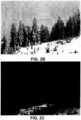
- the image ( Fig. 2A ) has a high black level. Darker details are surrounded closely by white features. In this example case the desired brightness of the image exceeds the capability of the LDR projector 16.
- the LDR projector 16 may be controlled to output as much light as it can (see Fig. 2B ) and the HDR projector 18 may be controlled to supplement some of the brighter features to simply increase the overall brightness of the image as shown in Fig. 2C .
- This image does not have very high dynamic range.
- the LDR projector 16 is sufficiently bright to produce the image at the desired level. In this case the LDR projector 16 may simply show the input image "as is" ( Fig. 3B ) and the HDR projector 18 may output nothing or be off ( Fig. 3C ).
- This image ( Fig. 4A ) shows some detail in the darker areas so the image does not have a very low black level. Brighter parts of the image exceed the brightness capability of the LDR projector 16.
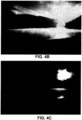
- the LDR projector 16 may display an image as shown in Fig. 4B and the HDR projector 18 may display an image as shown in Fig. 4C .
- This image ( Fig. 5A ) has very low back levels with complete absence of detail in the darks. Due to the high expected brightness of the candle flame, the LDR projector 16 may be turned off altogether, or dimmed down by the use of an iris ( Fig. 5B ), and the HDR projector 18 may produce the entire image ( Fig. 5C ).
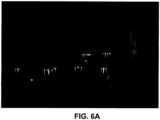
- Fig. 6A shows the peak brightness of the image.
- Fig. 6B shows the image output by the LDR projector 16 with an iris partially closed.
- Fig. 6C shows the (black/null) output of the HDR projector 18.
- Low dynamic range projectors often produce a dark grey image when attempting to show black due to limitations of light-modulator technology.
- the brightest areas have luminances lower than the peak luminance of the projector.
- better contrast can be achieved by dimming the light source.
- the amount of detail in dark areas of a target image can be determined to be of higher perceptual importance to the viewer.
- bright content may be sacrificed by dimming the projector to regain deeper black levels.
- Most low dynamic range projectors are lamp based and cannot easily be dimmed or turned on and off (to create pure black) on a per scene basis due to warm-up issues.
- an iris can be placed in the optical path (e.g. over the lens). The iris may then be made smaller to improve the black level of the projected image. Also note that the iris is not binary; an iris may be opened to a size dictated by the desired image black level. It is assumed that the iris can change size with sufficient speed as to not create a noticeable lag when changing scenes.
- the iris function may also be implemented by some other electrical or mechanical means such as an LCD plate (electrically dimmable) or a high speed shutter rapidly closing and opening.
- the LDR projector 16 has a solid state light source that has a light output that can be controlled, an iris may not be needed and the light source may be dimmed in an amount such that its light output is equivalent to the light that would have been available through a constricted iris.
- a high dynamic range projector may optionally include a globally dimmable solid state light source and/or an iris.
- HDR projector 18 shows poorer image quality due to field non-uniformity or other artifacts, having at least a base amount of light from the LDR projector can help to perceptually mitigate the artifacts.
- the HDR projector 18 may be used to correct for the non-uniformity of the light field.
- P e.g. pixel values
- S source illumination
- O F(P,S)
- Displays in a network can be connected either in series to form a single optical path, or in parallel to combine multiple optical paths, or in a combination of serial and parallel designs.
- FIG. 8 An example of a serial connection for two displays is shown in Fig. 8 for a system comprising two amplitude modulators connected in series. Such an arrangement is used in some Extended Dynamic Range (EDR) projectors which compensate for limited contrast ratios of individual amplitude modulators by cascading the modulators. The output contrast is consequently the product of the contrast ratios of the two modulators.
- EDR Extended Dynamic Range
- FIG. 9 An example of a parallel arrangement is found in projector super-resolution applications, in which the output images from multiple projectors are overlapped with a slight deregistration in order to generate higher spatial frequency features than are present in an image from a single projector. This arrangement is shown in Fig. 9 .
- the optical paths of two amplitude modulating projectors are combined (by the projection screen) to produce an output image.
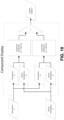
- Compound displays can consequently be represented as specific types of abstract displays, which can in turn be arranged into networks and/or grouped to form higher level compound displays.
- component display image formation models, Fi are known a mathematical image formation model of the overall display system can be expressed via combinations of the serial and parallel formulas. Such an image formation model may be applied to optimize the operation of a display system.
- a display system as an abstract (possibly compound) display that takes parameters, P, and source illumination, S, to produce an output image can allow the parameters to be jointly optimized.
- Such a system is depicted in Fig 11 , in which display parameter optimization is performed to determine the parameters, P, and illumination, S, required to reproduce an input target image, T, for an abstract (possibly compound) display.
- the simulated (or measured) output of this display is then fed back through the system to several modules: an image fidelity model, a system constraint model and a quality heuristics model.
- the models used by the system implicitly have access to target image, source illumination and current parameter selection.
- a camera located to acquire images showing the output of the display may also be incorporated into the feedback loop. Optimization may be performed using a cost function that includes differences between images acquired by the camera and the desired output of the display system (a target image).
- Each of the models attempts to correct for deviations of the output image or parameter selection from desirable properties.
- One common model is image fidelity: it is desirable that the image produced by the system closely approximate the target image, T, or a modified version of the target image, perhaps one where perceptual factors are taken into account. Errors between the output image and target image are used by the model to compute parameter adjustments. Optimization may proceed until either convergence of the parameters is achieved or a time budget is exhausted.
- the system constraints model ensures that the parameter selection result in physically realizable (and desirable configurations). Such criteria can include requiring that source illumination profiles are within the available power or that parameters for modulators vary between opaque and transmissive, i.e. do not produce light. Desirable configurations may include choosing parameters that have spatial or temporal coherence, that are within a certain range (see e.g. the LCoS linearity discussion earlier), or parameters that minimize power usage and/or maximize component lifetime.
- Image quality heuristics may be used to compensate for behaviors that are not easily modeled or which are costly to model for the image formation models.
- Image quality heuristics may include moiré, diffraction, temporal behavior and color fringing, among other artifacts.
- the heuristics models are intended to help compensate for these using empirical image-quality criteria.
- Image quality heuristics can also be provided to adjust parameters to optimize for properties of human perception, such as veiling luminance, adaptation levels, mean picture levels, metamerism and variations in sensitivity to chroma/luma errors. Sensitivity to these properties can be exploited in content generation.
- Figure 12 shows HDR+LDR projector systems depicted in the above-described abstract display framework.
- the LDR and HDR projectors may themselves be compound displays, wherein an example not according to the invention having desirable properties for commercial applications has a relatively high power LDR projector that can achieve a full-screen white suitable for typical average picture levels combined with a lower-power HDR projector that can achieve much higher peak brightness but does not have the power to do so over the entire screen.
- Such a system can be vastly more efficient and less costly than building a single projector capable of increased full-screen white values due to distributions of luminance in typical images.
- Some example ways to provide such global dimming use an iris, a controllable shutter, and/or a variable output light source.
- the iris is a very simple display that modulates the intensity of the LDR projector, which could be replaced, in principle by a source, S1, for the LDR projector that can be dynamically modulated.
- the display parameter optimization searches for LDR parameters P1, Iris/drive level parameters P2 and HDR parameters P3 causing the output image O to best match the target image T.
- the image fidelity model is the function, C, which weights errors between the image produced by the system, F(P,S), to produce a scalar indicating how preferable the current set of parameters are.
- C Common examples for C are the mean squared error (MSE) or the mean absolute error (MAE).
- the functions Qi represent image quality heuristics/models which also produce scalar values indicating how preferable the current parameters are in terms of unmodeled artifacts, e.g. moiré, color fringing, or diffractions artifacts.
- the constants ⁇ and ⁇ i control the relative importance given to the various terms (which may be contradictory), providing a way for the content generation to favour one objective over another.
- the HDR projector is necessary for high luminance regions, it may be desirable, from an image quality perspective, to also make use of the HDR projector in regions below the full-screen white level of the LDR projector. This requires portioning content between the two projectors.
- One straightforward way of approaching this is to blur or diffuse the mask used by the HDR projector, for example by blurring a dilated binary mask of pixels above the LDR projector full-screen white.
- a more sophisticated approach could compute approximations of the veiling luminance at each pixel in order to adjust blending parameters dynamically.
- the blending factors may be dynamically adjusted spatially within a scene to achieve desired local behaviour. For instance, low luminance content adjacent to high-luminance regions may be obscured by veiling luminance of highlights. In this case, neither of the LDR and HDR projectors need to display content for those regions. Alternatively, some scenes may have large bright regions and large dim regions. The adjustments discussed above can then be made, taking into account the scattering behavior of the projectors.
- the primary colours used in the HDR and LDR projectors differ, perhaps by design, it may be possible to extend the color gamut of the combined system. This can be achieved by mapping the target image to the appropriate color-space and determining what mixture of the two available sets of primaries best represents the target color, for instance choosing as broad a set of primaries as possible to improve metamerism.
- the process here is similar in principle to that used in extending the dynamic luminance range, as has been discussed throughout this document.
- HDR and LDR projectors are deregistered, it may be possible to increase the apparent resolution of the combined system to decrease aliasing near edges. This can be achieved by optimizing for a high resolution target image, which will cause the projector contributions between HDR and LDR to automatically adjust in order to best approximate the high spatial frequency features.
- R is a function modeling scatter from the viewing environment and F' is the image formation model for the system in a non-scattering viewing environment. Parameters for the displays optimized using this image formation model automatically attempt to compensate for the resulting scatter.
- a similar approach can use actual measurements of scattered light in place of the function R in order to dynamically compensate for light scattering from the viewing environment.
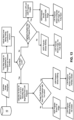
- Fig. 13 details one approach to determining what image will be shown by what projector, and how they are computed.
- the decision boxes depicted in Fig. 13 may incorporate a small amount of temporal hysteresis such that the LDR and HDR projectors will not bounce back and forth about a threshold from image to image.
- the "Tone Map Image” operation examines the luminance levels (if available) in the incoming image from image storage 10 and maps them to the capabilities of the combined LDR and HDR projector. This operation also takes in account the ambient light level when mapping the darker areas of the image, and the maximum overall luminance the observer would be comfortable with.
- the "Adjust Black Level" operation will increase the black level of the mapped image in cases where the observer will not be able to perceive the lower black level.
- An example of this would be black text in a white field where veiling luminance would not allow an observer to distinguish a very low black level from a slightly elevated one.
- a forward model of the projectors may be used (to predict halo from brightness).
- an iris size (the amount of light attenuated by the iris or by dimming a light source) may be calculated to compensate for the elevated native black level of the LDR projector. Shrinking the iris will also lower the peak brightness available from the LDR projector. The reduced peak brightness may be computed as well.
- the HDR projector may be used to generate the entire image. Note that as explained in the iris section above, it may be desired to never completely block all light from the LDR projector.
- threshold banding would be in the small pixel areas surrounding a bright feature. Here both projectors would contribute light and sum together to create the pixels. The size of this area can be calculated from the veiling luminance effect or simply a fixed number of pixels when there is a fairly soft transition between the highlight and the adjacent features (bright spot on a gradient).
- Fig. 14 schematically shows a projection system with two imaging elements 28, 30, in which an auxiliary booster light source 26 is used when required to reproduce certain high brightness and/or low contrast images.
- High dynamic range projectors use two or more imaging stages to lower black levels when generating images. Each one of these image stages has a loss associated with it so when creating very bright images there is far more light loss in a multi stage projector as compared with a single stage projector. Light can be added when required before the final imaging stage to boost the efficiency of the system when low black levels are not required.
- Image forming elements used in the light path of projection systems are non-ideal in nature. When forming an image they allow light to leak through in dark areas and absorb some light in bright areas at the expense of overall contrast. To address this, projector manufacturers have made systems with multiple imaging elements to decrease the amount of light leaking through the system in dark areas. This in turn has required a much brighter light source to compensate for the transmission losses through two (or more) imaging elements in bright areas. These projectors show dramatically lower operational efficiency when showing bright images as compared with single stage projectors.
- a projection system examines the nature of the image being projected and in the case of a low contrast high brightness image will add a calculated amount of uniform light before the final imaging stage. The added light will then only have to travel through a single imaging stage and thus incur far lower transmission losses. Thus, the operational efficiency of the system when producing bright images will be substantially increased. When producing images that require far less light and higher contrast, little or no light will be added before the last imaging elements to preserve the low black levels expected of a multiple stage system.
- boost light delivered to the second imaging stage be uniform or even.
- the booster light is non-uniform.
- An example application of this is in the case where a first imaging stage provides a light output that includes undesired light patches or other artifacts.
- the first stage is a light steering stage the first stage may provide static artifacts that are not steerable (for example a global roll-off of intensity towards the edges, or visible patches and stripes from different laser diodes that for one reason or another are not corrected for).
- the booster light may be structured in such a way that the sum of the booster light and the artifacts is uniform or near uniform illumination. This may be done by providing a non-uniform pattern of booster light inverse to the pattern of artifacts from the first stage.
- Fig 14 shows a "main light source” 24 and a “boost light source” 26.
- the light output of both light sources 24, 26 may be controlled in an independent fashion.
- the "main light source” 24 is expected to illuminate the first imaging element 28 in an even, or otherwise defined manner.
- the "boost light source” 26 is expected to illuminate the last imaging element 30.
- the purpose of the first imaging element 28 is to block light or steer light away from darker parts of the image such that the last imaging element 30 will not have to block much light from darker parts of the image being projected, leading to a high contrast image when desired.
- the first imaging element may, for example, modulate the phase and/or intensity of light from the main light source 24.
- the "last imaging element" 30 can be paired such that the boost light source has its own independent light path to the screen. This may be desirable in a very high power system when a single final stage imaging element may not be able to handle the thermal stress or intensity associated with both light paths being summed on its surface.
- the methods can be implemented separately for each color primary in the system or operated in a color field sequential manner on one or more example implementations.
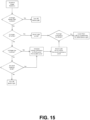
- Fig. 15 is a flow chart illustrating an intensity control method for the light sources in such a projection system.
- Such a method may be implemented in a controller for a display.
- the method is implemented in an image processing system that provides output image data accompanied by control signals for light sources.
- the boost light will be active when displaying low contrast imagery or when veiling luminance in the observer's eye or other optical scatter in the system or environment masks surrounding dark areas such that elevating the intensity of those dark areas does not result in noticeable degradation of the displayed image.
- Image statistics for example a histogram of the luminance distribution within an image, or other methods may be employed to determine the overall contrast requirements of the image.
- the boost light source may be used whenever possible as it is a more efficient light path than from the main light source and may always be used to provide brightness up to the darkest level present in an image.
- the main light source may be dimmed to compensate for light being added to the image by the boost light source.
- Fig 16 illustrates example images with different characteristics such as peak luminance, mean luminance and black level as well as sensible intensity levels for a auxiliary (boost) light source.
- Cases A and H show an image that is uniformly white at full intensity.
- the boost light can drive higher than the lowest level due to veiling luminance effects.
- Cases P and Q are also affected by veiling luminance and allow some light to come from the boost light.
- the boost light drives to the lowest brightness level present in the image.
- the boost light may be provided at a level determined by multiplying the lowest luminance level in the image by a factor. The factor may be based on the contrast capability of the second modulator.
- the booster light may be provided with a luminance sufficient to achieve 2000cd/m 2 with a fully open modulator C2 while allowing the light level to be reduced to 1cd/m 2 by setting the second modulator to its least light-transmitting state.
- a dark patch exceeds a threshold size such that it will not be masked by a veiling luminance effect, the boost light will be completely turned off and the non-black area of the screen will be illuminated through two image forming elements in series - drastically reducing the amount of light leaking through into the dark areas.
- a threshold size such that it will not be masked by a veiling luminance effect
- the boost light will be completely turned off and the non-black area of the screen will be illuminated through two image forming elements in series - drastically reducing the amount of light leaking through into the dark areas.
- E, F, G, R, S, T, and U there is enough dark content that the boost light is powered off to preserve the black levels.
- boost light and the main light source are distinct from one another.
- an optical system is provided that can direct some or all light from a main light source directly onto the last imaging element bypassing the first imaging element.
- a variable beam splitter may be applied to divert some light from a main light source onto the last imaging element.
- Some embodiments have both a separate boost light source and a provision for diverting light from the main light source onto the last imaging element.
- an optical element or elements are provided to combine light from the boost light source with light that has been modulated by the first imaging element and to direct the combined light onto the last imaging element.
- the optical element or elements comprises a prism in some embodiments.
- the boost light source comprises a plurality of light sources such as a plurality of light-emitting diodes (LEDs).
- the boost light source is arranged around an outer perimeter of the first imaging element.
- the boost light source may comprise a ring of LEDs. Suitable reflectors, diffusers, spaces and/or other optical elements may be provided to cause light from the boost light source to be evenly distributed on the last imaging element.
- Figures 2A to 6A show example images in five cases with different characteristics which are discussed above. The following explains by way of example how an auxiliary (booster) light source may be controlled for each of these 5 cases.
- the projector system used in the following examples may include a high efficient projector with steerable light source (main light source and first imaging element), a secondary imager and a booster stage that illuminates only the secondary imager.
- the secondary imager may, for example, comprise a reflective or transmissive spatial light modulator such as a LCD panel, LCOS, DMD, reflective LCD, or the like.
- the boost stage is used to illuminate most of the image.
- the first, steering and high contrast stage is used to add minimal highlights to the image. Little steering is required.
- the boost stage is used to illuminate the entire image.
- the steering stage is not used.
- the boost stage is full on.
- the steering stage is also full on providing maximum steering.
- the boost stage is off.
- the image is created using the steering stage only.
- the boost stage in on, but at reduced intensity to preserve some of the black level in the image.
- the steering stage is off as no highlights are needed.
- Stereoscopic image pairs comprise an image intended for viewing with the right eye and an image intended for viewing with the left eye.
- the disparity of the images creates a depth effect. No disparity will render images perceived to be in the plane of the projection screen.
- a disparity between left and right eye images will render objects to be perceived away from the projection screen plane, either closer to the viewer (audience) or, if inverted further away (perceived to be behind the screen plane).
- One characteristic of cinematic and other stereoscopic image content is that a pleasant viewing experience is more likely to be achieved if the disparity between left and right eye views is not too great (for example, depicted objects are not perceived as being too close to the viewer).
- the differences between the left and right eye views in stereoscopic image pairs are therefore typically kept small. Even in image pairs with depicted content that is perceived as being very close to the viewer (or very far away), many image areas in the left and right eye views will typically be the same because in almost all cases only some objects will be rendered as being close or far relative to the viewer.
- Projection systems are set up to produce different images for the left and right eyes which have different corresponding (to the filter at right and left eye) light properties, for example narrow band primaries different for left and right eye view, or clockwise and counterclockwise circularly polarized light, or light with orthogonal linear polarization states, or temporal light fields matching the temporal shutter at the eye or the polarization of the polarization switch.
- light properties for example narrow band primaries different for left and right eye view, or clockwise and counterclockwise circularly polarized light, or light with orthogonal linear polarization states, or temporal light fields matching the temporal shutter at the eye or the polarization of the polarization switch.
- one projector in a non-stereoscopic mode with a light source that is compatible with both the left and the right eye filters (for example a broadband light source in the case of a system based on color notch filters, or a randomly polarized system in the case of either the circular or linearly polarized filter system or a permanently ON light source in case of any temporal shutter filtering system).
- the non-stereoscopic projector will create those parts of an image that are common to both the left and the right eye view.
- a second projector may then be used to display the parts of the images that differ between the left and right eye views.
- the second projector projects light having the properties required for the left and the right eye filters (wavelength, or polarization, or temporal image fields).
- the power requirements for the second projector can be lower as the image regions with disparity between left and right are typically not large relative to all pixels of the image.
- Light steering may be used to steer light to the display areas corresponding to depicted objects perceived as being out of the plane of the display screen.
- a low power secondary projector can cost effectively be added to upgrade and enable an existing non-stereoscopic projection system to display stereoscopic images.
- Embodiments of the invention may be implemented using specifically designed hardware, configurable hardware, programmable data processors configured by the provision of software (which may optionally comprise "firmware") capable of executing on the data processors, special purpose computers or data processors that are specifically programmed, configured, or constructed to perform one or more steps in the method of the invention.
- specifically designed hardware are: logic circuits, application-specific integrated circuits ("ASICs"), large scale integrated circuits ("LSIs”), very large scale integrated circuits (“VLSIs”), and the like.
- ASICs application-specific integrated circuits
- LSIs large scale integrated circuits
- VLSIs very large scale integrated circuits
- configurable hardware are: one or more programmable logic devices such as programmable array logic (“PALs”), programmable logic arrays (“PLAs”), and field programmable gate arrays (“FPGAs”)).
- PALs programmable array logic
- PLAs programmable logic arrays
- FPGAs field programmable gate arrays
- programmable data processors are: microprocessors, digital signal processors ("DSPs"), embedded processors, graphics processors, math co-processors, general purpose computers, server computers, cloud computers, mainframe computers, computer workstations, and the like.
- DSPs digital signal processors
- embedded processors graphics processors
- math co-processors general purpose computers
- server computers cloud computers
- mainframe computers mainframe computers
- computer workstations and the like.
- one or more data processors in a control circuit for a device may implement methods as described herein by executing software instructions in a program memory accessible to the processors.
- processes or blocks are presented in a given order, alternative examples may perform routines having steps, or employ systems having blocks, in a different order, and some processes or blocks may be deleted, moved, added, subdivided, combined, and/or modified to provide alternative or subcombinations. Each of these processes or blocks may be implemented in a variety of different ways. Also, while processes or blocks are at times shown as being performed in series, these processes or blocks may instead be performed in parallel, or may be performed at different times.
- the invention's method may also be provided when executing its steps based on steps of a program product.
- the program product may comprise any non-transitory medium which carries a set of computer-readable instructions which, when executed by a data processor, cause the data processor to execute a method of the invention.
- Program products may be in any of a wide variety of forms.
- the program product may comprise, for example, non-transitory media such as magnetic data storage media including floppy diskettes, hard disk drives, optical data storage media including CD ROMs, DVDs, electronic data storage media including ROMs, flash RAM, EPROMs, hardwired or preprogrammed chips (e.g., EEPROM semiconductor chips), nanotechnology memory, or the like.
- the computer-readable signals on the program product may optionally be compressed or encrypted.
- the invention's method may be implemented using software.
- "software” includes any instructions executed on a processor, and may include (but is not limited to) firmware, resident software, microcode, and the like. Both processing hardware and software may be centralized or distributed (or a combination thereof), in whole or in part, as known to those skilled in the art. For example, software and other modules may be accessible via local memory, via a network, via a browser or other application in a distributed computing context, or via other means suitable for the purposes described above.
Landscapes
- Engineering & Computer Science (AREA)
- Multimedia (AREA)
- Signal Processing (AREA)
- Physics & Mathematics (AREA)
- General Physics & Mathematics (AREA)
- Optics & Photonics (AREA)
- Transforming Electric Information Into Light Information (AREA)
- Projection Apparatus (AREA)
- Control Of Indicators Other Than Cathode Ray Tubes (AREA)
- Controls And Circuits For Display Device (AREA)
- Liquid Crystal (AREA)
- Liquid Crystal Display Device Control (AREA)
Claims (15)
- Lichtprojektor zum Anzeigen eines durch Bilddaten definierten Bildes, wobei der Lichtprojektor umfasst:- eine Hauptlichtquelle (24),- ein erstes Abbildungselement (28), das dazu konfiguriert ist, sichtbares Licht von der Hauptlichtquelle (24) zu modulieren,- ein zweites Abbildungselement (30), das dazu konfiguriert ist, das von dem ersten Abbildungselement (28) erzeugte modulierte sichtbare Licht weiter zu modulieren,- eine Verstärkungslichtquelle (26), die dazu konfiguriert ist, dem zweiten Abbildungselement sichtbares Verstärkungslicht zur Modulation durch das zweite Abbildungselement zuzuführen, wobei das sichtbare Verstärkungslicht von dem ersten Abbildungselement (28) nicht moduliert wird, und- ein Steuergerät, das dazu konfiguriert ist,die Bilddaten zu verarbeiten undSteuersignale für das erste Abbildungselement (28), das zweite Abbildungselement (30), die Hauptlichtquelle (24) und die Verstärkungslichtquelle (26) auszugeben,dadurch gekennzeichnet, dass
das Steuergerät dazu konfiguriert ist, einen niedrigsten Luminanzpegel in dem Bild zu bestimmen und, wenn niedrige Schwarzpegel nicht erforderlich sind, das Steuersignal für die Verstärkungslichtquelle (26) so ausgeben, dass das sichtbare Verstärkungslicht mit einem Pegel hinzugefügt wird, der größer oder gleich dem niedrigsten Luminanzpegel in dem Bild ist. - Lichtprojektor nach Anspruch 1, wobei das Steuergerät ferner dazu konfiguriert ist, die Hauptlichtquelle (24) zu dimmen, wenn keine niedrigen Schwarzpegel erforderlich sind, um das sichtbare Verstärkungslicht zu kompensieren, das dem Bild durch die Verstärkungslichtquelle (26) hinzugefügt wird.
- Lichtprojektor nach Anspruch 1 oder 2, wobei das erste Abbildungselement (28) dazu konfiguriert ist, eine oder beide von der Phase und der Amplitude des Lichts von der Hauptlichtquelle (24) zu modulieren.
- Lichtprojektor nach einem der Ansprüche 1 bis 3,wobei die Verstärkungslichtquelle (26) von der Hauptlichtquelle (24) getrennt ist und mehrere Lichtquellen umfasst undwobei die mehreren Lichtquellen vorzugsweise um einen äußeren Umfang des ersten Abbildungselements (28) angeordnet sind.
- Lichtprojektor nach einem der Ansprüche 1 bis 4,wobei die Verstärkungslichtquelle (26) von der Hauptlichtquelle (24) getrennt ist und mehrere Lichtquellen umfasst undwobei die mehreren Lichtquellen einzeln steuerbar ist, um ein gewünschtes Muster von sichtbarem Verstärkungslicht auf dem zweiten Abbildungselement (30) zu erzeugen.
- Lichtprojektor nach einem der Ansprüche 1 bis 5, wobei das Steuergerät ferner dazu konfiguriert ist,- einen Kontrast des Bildes zu bestimmen,- eine Schleierluminanz zu simulieren, wenn der Kontrast unter einem Schwellenwert liegt,- wenn der Kontrast unter einem Schwellenwert liegt, einen niedrigsten wahrnehmbaren Luminanzpegel in dem Bild basierend auf der Schleierluminanz zu bestimmen und- wenn der Kontrast unter einem Schwellenwert liegt, das sichtbare Verstärkungslicht mit einem Pegel hinzuzufügen, der dem niedrigsten wahrnehmbaren Luminanzpegel entspricht.
- Lichtprojektor nach Anspruch 6, wobei das Steuergerät ferner dazu konfiguriert ist:- dunkle Merkmale in dem Bild zu identifizieren, wenn der Kontrast nicht unter einem Schwellenwert liegt, und- wenn alle dunklen Merkmale kleiner als eine Schwellengröße sind, das sichtbare Verstärkungslicht mit dem dem niedrigsten wahrnehmbaren Luminanzpegel entsprechenden Pegel hinzuzufügen.
- Lichtprojektor nach Anspruch 7, wobei das Steuergerät ferner dazu konfiguriert ist:
die Verstärkungslichtquelle (26) auszuschalten, wenn eines der dunklen Merkmale größer als die Schwellengröße ist, und/oder- die Verstärkungslichtquelle (26) auszuschalten, wenn das Bild überwiegend dunkel ist. - Lichtprojektor nach einem der Ansprüche 1 bis 8, wobei das zweite Abbildungselement (30) einen räumlichen Lichtmodulator, vorzugsweise ein LCD-Panel, LCOS, reflektierendes LCD-Panel oder DMD, umfasst.
- Verfahren zum Anzeigen eines durch Bilddaten definierten Bildes, wobei das Verfahren umfasst:- Modulieren von einer Hauptlichtquelle (24) gelieferten sichtbaren Lichts unter Verwendung eines ersten Abbildungselements (28),- Bereitstellen von sichtbarem Verstärkungslicht für ein zweites Abbildungselement (39) unter Verwendung einer Verstärkungslichtquelle (26), wobei das sichtbare Verstärkungslicht nicht durch das erste Abbildungselement (28) moduliert wird,- Kombinieren des sichtbaren Verstärkungslichts und des modulierten sichtbaren Lichts durch Beleuchten einer Oberfläche des zweiten Abbildungselements (30) sowohl mit dem sichtbaren Verstärkungslicht als auch mit dem modulierten sichtbaren Licht,- weiteres Modulieren des kombinierten Lichts unter Verwendung des zweiten Abbildungselements (30),- Verarbeiten der Bilddaten und- Ausgeben von Steuersignalen für das erste Abbildungselement (28), das zweite Abbildungselement (30), die Hauptlichtquelle (24) und die Verstärkungslichtquelle (26),
dadurch gekennzeichnet, dass es ferner umfasstBestimmen des niedrigsten Luminanzpegels in dem Bild,Ausgeben des Steuersignals für die Verstärkungslichtquelle (26), wenn keine niedrigen Schwarzpegel erforderlich sind, so dass das sichtbare Verstärkungslicht mit einem Pegel hinzugefügt wird, der größer oder gleich dem niedrigsten Luminanzpegel in dem Bild ist. - Verfahren nach Anspruch 10, das ferner umfassend Dimmen der Hauptlichtquelle (24), wenn keine niedrigen Schwarzpegel erforderlich sind, um das sichtbare Verstärkungslicht zu kompensieren, das dem Bild durch die Verstärkungslichtquelle (26) hinzugefügt wird.
- Verfahren nach Anspruch 10 oder 11, wobei das sichtbare Verstärkungslicht eine strukturierte Beleuchtung umfasst, die dazu ausgelegt ist, die Oberfläche des zweiten Abbildungselements (30) gemäß einem gewünschten Luminanzprofil zu beleuchten.
- Verfahren nach Anspruch 12,wobei die strukturierte Beleuchtung auf einigen Teilen der Oberfläche des zweiten Abbildungselements (30) eine höhere Luminanz aufweist als in anderen Teilen der Oberfläche des zweiten Abbildungselements, undwobei die Luminanz des Teils mit der höchsten Luminanz der strukturierten Beleuchtung mindestens doppelt so hoch ist wie die Luminanz der Teile mit der niedrigsten Luminanz der strukturierten Beleuchtung.
- Verfahren nach einem der Ansprüche 10 bis 13, ferner umfassend:Bestimmen eines Kontrasts des Bildes,Identifizieren von dunklen Merkmalen in dem Bild, die eine Schwellengröße überschreiten, wenn der Kontrast nicht unter einem Schwellenwert liegt, und,Ausschalten der Verstärkungslichtquelle (26), wenn eines der dunklen Merkmale größer als die Schwellengröße ist.
- Verfahren nach einem der Ansprüche 10 bis 14, umfassendBestimmen eines Kontrasts des Bildes,Simulieren einer Schleierluminanz, wenn der Kontrast unter einem Schwellenwert liegt,Bestimmen, wenn der Kontrast niedriger als ein Schwellenwert ist, eines niedrigsten wahrnehmbaren Luminanzpegels in dem Bild auf der Grundlage der Schleierluminanz und,wenn der Kontrast unter einem Schwellenwert liegt, Hinzufügen des sichtbaren Verstärkungslichts mit einem Pegel, der dem niedrigsten wahrnehmbaren Luminanzpegel entspricht.
Applications Claiming Priority (3)
| Application Number | Priority Date | Filing Date | Title |
|---|---|---|---|
| US201461994002P | 2014-05-15 | 2014-05-15 | |
| US201562148041P | 2015-04-15 | 2015-04-15 | |
| PCT/CA2015/000324 WO2015172236A1 (en) | 2014-05-15 | 2015-05-15 | Optimizing drive schemes for multiple projector systems |
Related Child Applications (2)
| Application Number | Title | Priority Date | Filing Date |
|---|---|---|---|
| EP23211290.4 Division-Into | 2023-11-21 | ||
| EP23211338.1 Division-Into | 2023-11-21 |
Publications (4)
| Publication Number | Publication Date |
|---|---|
| EP3143763A1 EP3143763A1 (de) | 2017-03-22 |
| EP3143763A4 EP3143763A4 (de) | 2018-01-10 |
| EP3143763B1 true EP3143763B1 (de) | 2023-11-22 |
| EP3143763B8 EP3143763B8 (de) | 2023-12-27 |
Family
ID=54479080
Family Applications (1)
| Application Number | Title | Priority Date | Filing Date |
|---|---|---|---|
| EP15792616.3A Active EP3143763B8 (de) | 2014-05-15 | 2015-05-15 | Lichtprojektor und verfahren zur bildanzeige |
Country Status (6)
| Country | Link |
|---|---|
| US (6) | US20170150107A1 (de) |
| EP (1) | EP3143763B8 (de) |
| JP (3) | JP6788504B2 (de) |
| CN (2) | CN114554123B (de) |
| CA (1) | CA2917585C (de) |
| WO (1) | WO2015172236A1 (de) |
Families Citing this family (31)
| Publication number | Priority date | Publication date | Assignee | Title |
|---|---|---|---|---|
| JP3020476B2 (ja) | 1997-03-31 | 2000-03-15 | 倉敷紡績株式会社 | 加飾性多層成形体 |
| EP3697085B1 (de) * | 2013-10-10 | 2022-07-27 | Dolby Laboratories Licensing Corporation | Anzeige von dci und anderen inhalten auf einem projektor mit erweitertem dynamikbereich |
| CA3148330C (en) | 2013-10-20 | 2026-05-19 | Barco Visual Solutions, Inc. | Light field projectors and methods |
| CN114554123B (zh) * | 2014-05-15 | 2024-06-25 | Mtt创新公司 | 用于显示通过图像数据限定的图像的方法 |
| JP6791840B2 (ja) | 2014-08-14 | 2020-11-25 | エムティティ イノベーション インコーポレイテッドMtt Innovation Incorporated | 光源 |
| JP2017138350A (ja) * | 2016-02-01 | 2017-08-10 | アルプス電気株式会社 | 画像表示装置 |
| TWI764898B (zh) * | 2016-08-03 | 2022-05-21 | 日商新力股份有限公司 | 資訊處理裝置、資訊處理方法及程式 |
| EP3840370B1 (de) | 2016-09-30 | 2022-08-10 | Dolby Laboratories Licensing Corporation | Strahlkombination zur lichtreichen projektion |
| CN110383145B (zh) | 2017-02-03 | 2022-02-08 | 巴科股份有限公司 | 用于增强的图像投影的系统和方法 |
| CN114401389B (zh) * | 2017-05-12 | 2024-03-22 | Mtt创新公司 | 图像投影系统和方法 |
| CN107918802B (zh) * | 2017-09-30 | 2024-03-15 | 北京极智嘉科技股份有限公司 | 物品分拣方法、区域布局、分拣系统及路径优化方法 |
| US10488746B2 (en) | 2017-11-14 | 2019-11-26 | Dolby Laboratories Licensing Corporation | Aperture sharing for highlight projection |
| KR102516828B1 (ko) * | 2017-12-28 | 2023-03-31 | 삼성전자주식회사 | 영상 처리 장치, 영상 처리 방법 및 다중 스크린 디스플레이 |
| CN110275376B (zh) | 2018-03-16 | 2021-08-03 | 深圳光峰科技股份有限公司 | 显示设备及显示方法 |
| CN110278422B (zh) * | 2018-03-16 | 2022-01-11 | 深圳光峰科技股份有限公司 | 显示设备 |
| US10437120B1 (en) * | 2018-04-23 | 2019-10-08 | Omnivision Technologies, Inc. | Methods and systems for displaying high dynamic range images |
| GB201807461D0 (en) * | 2018-05-08 | 2018-06-20 | Barco Nv | Closed loop driving of a highlighter type projector |
| CN108600720B (zh) * | 2018-07-18 | 2024-02-20 | 中国电影器材有限责任公司 | 一种用于图像信号hdr投影的光源、装置、系统及方法 |
| US11297292B2 (en) * | 2018-07-19 | 2022-04-05 | Sharp Nec Display Solutions, Ltd. | Projector, stack display system, image display method, and program |
| CN112585532B (zh) * | 2018-08-31 | 2022-08-30 | 索尼公司 | 照明装置和显示设备 |
| CN110944161B (zh) * | 2018-09-21 | 2021-11-05 | 深圳光峰科技股份有限公司 | 投影系统及投影显示方法 |
| JP7309352B2 (ja) * | 2018-12-04 | 2023-07-18 | キヤノン株式会社 | 電子機器およびその制御方法 |
| CN110062184A (zh) * | 2019-04-09 | 2019-07-26 | 南昌航空大学 | 一种普遍适用的dmd集群控制系统及控制方法 |
| CN110430404B (zh) * | 2019-07-01 | 2022-07-01 | 中国电影器材有限责任公司 | 一种数字电影放映图像处理方法和数字电影放映系统 |
| JP7285481B2 (ja) * | 2019-07-30 | 2023-06-02 | パナソニックIpマネジメント株式会社 | 照明システム、及び、制御装置 |
| KR20230028303A (ko) * | 2020-06-23 | 2023-02-28 | 트리나미엑스 게엠베하 | 확산 조명 및 구조화 광을 위한 프로젝터 |
| CN112529794B (zh) * | 2020-11-30 | 2025-01-17 | 深圳市智能机器人研究院 | 高动态范围结构光三维测量方法、系统及介质 |
| KR20230026126A (ko) * | 2021-08-17 | 2023-02-24 | 삼성전자주식회사 | 전자 장치 및 이의 제어 방법 |
| CN118901095A (zh) | 2022-02-22 | 2024-11-05 | 巴科股份有限公司 | 用于调整数字图像的装置和方法 |
| JP2025048989A (ja) * | 2023-09-21 | 2025-04-03 | ソフトバンクグループ株式会社 | システム |
| WO2026015397A1 (en) * | 2024-07-12 | 2026-01-15 | Dolby Laboratories Licensing Corporation | High contrast imaging using multi-path projection systems |
Citations (1)
| Publication number | Priority date | Publication date | Assignee | Title |
|---|---|---|---|---|
| US20140043352A1 (en) * | 2011-04-19 | 2014-02-13 | Dolby Laboratories Licensing Corporation | High Luminance Projection Displays And Associated Methods |
Family Cites Families (168)
| Publication number | Priority date | Publication date | Assignee | Title |
|---|---|---|---|---|
| US956000A (en) | 1909-04-26 | 1910-04-26 | P & F Corbin | Lock. |
| US5287096A (en) | 1989-02-27 | 1994-02-15 | Texas Instruments Incorporated | Variable luminosity display system |
| JPH03280677A (ja) * | 1990-03-28 | 1991-12-11 | Toshiba Corp | マルチ映像表示装置の直流伝送量設定回路 |
| ES2142803T3 (es) | 1990-08-01 | 2000-05-01 | Diomed Ltd | Fuente luminosa de alta potencia. |
| US6392689B1 (en) | 1991-02-21 | 2002-05-21 | Eugene Dolgoff | System for displaying moving images pseudostereoscopically |
| JP3028891B2 (ja) | 1993-02-17 | 2000-04-04 | 株式会社日立製作所 | プロジェクタ装置のスクリーン |
| KR0163077B1 (ko) * | 1993-12-27 | 1999-01-15 | 사또오 후미오 | 표시장치 |
| US5490009A (en) | 1994-10-31 | 1996-02-06 | Texas Instruments Incorporated | Enhanced resolution for digital micro-mirror displays |
| FR2733062B1 (fr) | 1995-04-13 | 1997-06-27 | Thomson Multimedia Sa | Systeme de projection comportant un reflecteur et une lentille de champ a surface libre |
| US6417892B1 (en) * | 1995-05-23 | 2002-07-09 | Colorlink, Inc. | Color filters, sequencers and displays using color selective light modulators |
| US5886675A (en) * | 1995-07-05 | 1999-03-23 | Physical Optics Corporation | Autostereoscopic display system with fan-out multiplexer |
| JP3735158B2 (ja) | 1996-06-06 | 2006-01-18 | オリンパス株式会社 | 画像投影システム、画像処理装置 |
| GB2317290B (en) * | 1996-09-11 | 2000-12-06 | Seos Displays Ltd | Image display apparatus |
| US5715337A (en) | 1996-09-19 | 1998-02-03 | The Mirco Optical Corporation | Compact display system |
| US5953469A (en) | 1996-10-29 | 1999-09-14 | Xeotron Corporation | Optical device utilizing optical waveguides and mechanical light-switches |
| US6115022A (en) * | 1996-12-10 | 2000-09-05 | Metavision Corporation | Method and apparatus for adjusting multiple projected raster images |
| US5956000A (en) | 1997-05-12 | 1999-09-21 | Scitex Corporation Ltd. | Digital image display system and method |
| US6057537A (en) | 1997-09-29 | 2000-05-02 | Eastman Kodak Company | Optical scanner feedback system having a reflected cylinder lens |
| SE9800665D0 (sv) | 1998-03-02 | 1998-03-02 | Micronic Laser Systems Ab | Improved method for projection printing using a micromirror SLM |
| JP3832093B2 (ja) | 1998-05-26 | 2006-10-11 | セイコーエプソン株式会社 | 表示装置及び表示方法 |
| US6456339B1 (en) | 1998-07-31 | 2002-09-24 | Massachusetts Institute Of Technology | Super-resolution display |
| US6269175B1 (en) * | 1998-08-28 | 2001-07-31 | Sarnoff Corporation | Method and apparatus for enhancing regions of aligned images using flow estimation |
| US6590549B1 (en) | 1998-12-30 | 2003-07-08 | Texas Instruments Incorporated | Analog pulse width modulation of video data |
| US6406148B1 (en) | 1998-12-31 | 2002-06-18 | Texas Instruments Incorporated | Electronic color switching in field sequential video displays |
| US6570623B1 (en) | 1999-05-21 | 2003-05-27 | Princeton University | Optical blending for multi-projector display wall systems |
| GB9923428D0 (en) | 1999-10-04 | 1999-12-08 | Thomas Swan & Company Limited | Optical switch |
| DE60044840D1 (de) | 1999-11-05 | 2010-09-30 | Texas Instruments Inc | Sequentielle Fabrückgewinnung für Projektionssysteme |
| US7118226B2 (en) | 1999-11-05 | 2006-10-10 | Texas Instruments Incorporated | Sequential color recapture for image display systems |
| US6771272B2 (en) | 2000-03-17 | 2004-08-03 | Sun Microsystems, Inc. | Graphics system having a super-sampled sample buffer with hot spot correction |
| CA2412418C (en) | 2000-06-13 | 2006-08-08 | Panoram Technologies, Inc. | Method and apparatus for seamless integration of multiple video projectors |
| US6804406B1 (en) | 2000-08-30 | 2004-10-12 | Honeywell International Inc. | Electronic calibration for seamless tiled display using optical function generator |
| US6568816B2 (en) | 2000-10-04 | 2003-05-27 | Panoram Technologies, Inc. | Projection system and method for using a single light source to generate multiple images to be edge blended for arrayed or tiled display |
| JP2002116500A (ja) | 2000-10-05 | 2002-04-19 | Olympus Optical Co Ltd | 画像投影表示装置 |
| KR100938325B1 (ko) | 2001-06-13 | 2010-01-22 | 오르보테크 엘티디. | 에너지 전달 시스템 |
| JP2003107422A (ja) | 2001-07-26 | 2003-04-09 | Sony Corp | 液晶プロジェクタ装置 |
| US6733138B2 (en) | 2001-08-15 | 2004-05-11 | Mitsubishi Electric Research Laboratories, Inc. | Multi-projector mosaic with automatic registration |
| GB0121308D0 (en) | 2001-09-03 | 2001-10-24 | Thomas Swan & Company Ltd | Optical processing |
| JP2003125317A (ja) | 2001-10-11 | 2003-04-25 | Sony Corp | 映像投影システム、映像投影方法、映像信号処理装置、映像信号処理方法、映像投影装置、及び映像投影方法 |
| JP4348457B2 (ja) * | 2002-03-13 | 2009-10-21 | ドルビー ラボラトリーズ ライセンシング コーポレイション | 高ダイナミックレンジのディスプレイ、ディスプレイコントローラ及び画像表示方法 |
| JP3991764B2 (ja) | 2002-05-10 | 2007-10-17 | セイコーエプソン株式会社 | 照明装置および投射型表示装置 |
| US20030218590A1 (en) | 2002-05-23 | 2003-11-27 | Kiser David K. | Optics engine having multi-array spatial light modulating device and method of operation |
| KR100648904B1 (ko) | 2002-07-10 | 2006-11-24 | 후지 샤신 필름 가부시기가이샤 | 디스플레이장치 |
| US7440160B2 (en) | 2002-11-15 | 2008-10-21 | Merck Patent Gmbh | Electro-optical light modulating element, electro-optical display and modulating medium |
| GB0228089D0 (en) * | 2002-12-02 | 2003-01-08 | Seos Ltd | Dynamic range enhancement of image display apparatus |
| KR20050084248A (ko) * | 2002-12-11 | 2005-08-26 | 코닌클리케 필립스 일렉트로닉스 엔.브이. | 콘트라스트 균일성 보정을 구비한 프로젝션 시스템 |
| GB2398130A (en) | 2003-02-05 | 2004-08-11 | Ocuity Ltd | Switchable active lens for display apparatus |
| US7097311B2 (en) | 2003-04-19 | 2006-08-29 | University Of Kentucky Research Foundation | Super-resolution overlay in multi-projector displays |
| TWI261723B (en) | 2003-05-09 | 2006-09-11 | Benq Corp | Projector for adjusting a screen size and brightness depending on various environment and a method thereof |
| US7206133B2 (en) | 2003-05-22 | 2007-04-17 | Optical Research Associates | Light distribution apparatus and methods for illuminating optical systems |
| US7521651B2 (en) | 2003-09-12 | 2009-04-21 | Orbotech Ltd | Multiple beam micro-machining system and method |
| US6870682B1 (en) | 2003-09-30 | 2005-03-22 | Institut National D'optique | Apparatus for reshaping an optical beam bundle |
| EP1711854A4 (de) * | 2003-10-17 | 2009-08-19 | Explay Ltd | Optisches system und verfahren zur verwendung in projektionssystemen |
| JP2005181965A (ja) * | 2003-11-25 | 2005-07-07 | Ricoh Co Ltd | 空間光変調器及び表示装置及び投射表示装置 |
| GB2408646B (en) * | 2003-11-28 | 2008-11-26 | Seos Ltd | Image Display Apparatus with Night Vision Goggle Compatibility |
| JP2005242165A (ja) * | 2004-02-27 | 2005-09-08 | Seiko Epson Corp | 光変調装置および投射型表示装置、並びに光変調方法および画像表示方法 |
| JP2005250235A (ja) * | 2004-03-05 | 2005-09-15 | Seiko Epson Corp | 光変調装置、光学表示装置、光変調制御プログラム及び光学表示装置制御プログラム、並びに光変調制御方法及び光学表示装置制御方法 |
| JP2005258214A (ja) | 2004-03-12 | 2005-09-22 | Goto Optical Mfg Co | プラネタリウム施設における投映方法 |
| US7307704B2 (en) | 2004-04-19 | 2007-12-11 | Carrier Corporation | Light delivery control system and method |
| DE102004020996A1 (de) | 2004-04-19 | 2005-11-03 | Carl Zeiss Industrielle Messtechnik Gmbh | Koordinatenmessgerät zum messtechnischen Bestimmen einer Koordinate an einem Messobjekt |
| CA2567040C (en) * | 2004-05-05 | 2013-08-06 | Imax Corporation | Multiple source high performance stereographic projection system |
| JP4740857B2 (ja) | 2004-07-28 | 2011-08-03 | パナソニック株式会社 | 映像表示装置及び映像表示システム |
| US7471300B2 (en) | 2005-01-18 | 2008-12-30 | Intel Corporation | Progressive data delivery to spatial light modulators |
| JP4285425B2 (ja) | 2005-03-09 | 2009-06-24 | セイコーエプソン株式会社 | 画像表示装置及びプロジェクタ |
| JP4893004B2 (ja) * | 2005-03-24 | 2012-03-07 | セイコーエプソン株式会社 | プロジェクタ |
| US8567953B2 (en) | 2005-04-26 | 2013-10-29 | Imax Corporation | Systems and methods for projecting composite images |
| DE102005021155B3 (de) | 2005-04-29 | 2006-11-23 | Seereal Technologies Gmbh | Steuerbare Beleuchtungseinrichtung |
| EP1734771A1 (de) | 2005-06-14 | 2006-12-20 | SONY DEUTSCHLAND GmbH | Beleuchtungsoptik, Beleuchtungseinheit und Bilderzeugungseinheit |
| GB0512179D0 (en) | 2005-06-15 | 2005-07-20 | Light Blue Optics Ltd | Holographic dispaly devices |
| JP4407585B2 (ja) | 2005-07-22 | 2010-02-03 | セイコーエプソン株式会社 | 照明装置及び画像表示装置、並びにプロジェクタ |
| JP4821204B2 (ja) | 2005-07-22 | 2011-11-24 | セイコーエプソン株式会社 | 照明装置及び画像表示装置、並びにプロジェクタ |
| US7438423B2 (en) * | 2005-08-29 | 2008-10-21 | 3M Innovative Properties Company | Illumination system and projection system incorporating same |
| US20070091277A1 (en) * | 2005-10-26 | 2007-04-26 | Niranjan Damera-Venkata | Luminance based multiple projector system |
| JP2007192919A (ja) | 2006-01-17 | 2007-08-02 | Olympus Corp | 画像表示装置 |
| JP2007206343A (ja) | 2006-02-01 | 2007-08-16 | Seiko Epson Corp | 光学表示装置及びその方法 |
| JP2007240931A (ja) * | 2006-03-09 | 2007-09-20 | Seiko Epson Corp | 画像表示装置及びプロジェクタ |
| GB2438026A (en) | 2006-05-11 | 2007-11-14 | Univ Cambridge Tech | Phase retrevial in hologram generation using amplitude and phase feedback |
| JP2008026879A (ja) * | 2006-06-19 | 2008-02-07 | Seiko Epson Corp | 表示システムおよび表示方法 |
| JP2008015064A (ja) | 2006-07-04 | 2008-01-24 | Seiko Epson Corp | 照明装置及びプロジェクタ |
| JP4210863B2 (ja) * | 2006-07-06 | 2009-01-21 | セイコーエプソン株式会社 | 画像処理システム、表示装置、プログラムおよび情報記憶媒体 |
| KR100815440B1 (ko) | 2006-07-28 | 2008-03-20 | 주식회사 나노브릭 | 마이크로-전자기계 시스템 기반의 광 프로젝션 엔진과 그제조 방법 |
| JP5011919B2 (ja) | 2006-09-29 | 2012-08-29 | セイコーエプソン株式会社 | 照明装置及びプロジェクタ |
| WO2008049917A1 (en) | 2006-10-26 | 2008-05-02 | Seereal Technologies S.A. | Holographic display device comprising magneto-optical spatial light modulator |
| GB0624092D0 (en) | 2006-12-01 | 2007-01-10 | Seos Ltd | Image display apparatus |
| GB2445164A (en) | 2006-12-21 | 2008-07-02 | Light Blue Optics Ltd | Holographic image display systems |
| US8749463B2 (en) | 2007-01-19 | 2014-06-10 | Hamamatsu Photonics K.K. | Phase-modulating apparatus |
| JP4998002B2 (ja) | 2007-02-13 | 2012-08-15 | セイコーエプソン株式会社 | プロジェクタ |
| CN101295123B (zh) * | 2007-04-25 | 2012-07-25 | 中国科学院光电研究院 | 一种基于闪耀光栅光调制器的显示系统 |
| US7936361B2 (en) * | 2007-04-30 | 2011-05-03 | Hewlett-Packard Development Company, L.P. | System and method for masking and overlaying images in multiple projector system |
| DE102007023785B4 (de) | 2007-05-16 | 2014-06-18 | Seereal Technologies S.A. | Analytisches Verfahren zu Berechnung von Videohologrammen in Echtzeit und holographische Wiedergabeeinrichtung |
| DE102007025069B4 (de) | 2007-05-21 | 2018-05-24 | Seereal Technologies S.A. | Holographisches Rekonstruktionssystem |
| US7878657B2 (en) | 2007-06-27 | 2011-02-01 | Prysm, Inc. | Servo feedback control based on invisible scanning servo beam in scanning beam display systems with light-emitting screens |
| EP2174176A1 (de) | 2007-07-17 | 2010-04-14 | Explay Ltd. | Kohärentes abbildungsverfahren der laserprojektion und vorrichtung dafür |
| JP4475302B2 (ja) | 2007-08-07 | 2010-06-09 | セイコーエプソン株式会社 | プロジェクタ及び投射装置 |
| US8319699B2 (en) * | 2007-08-09 | 2012-11-27 | Barco N.V. | Multiple display channel system with high dynamic range |
| EP2193657A2 (de) | 2007-09-25 | 2010-06-09 | Explay Ltd. | Mikro-projektor |
| US7862183B2 (en) | 2007-10-16 | 2011-01-04 | Alcatel-Lucent Usa Inc. | Speckle reduction using a tunable liquid lens |
| JP5042781B2 (ja) | 2007-11-06 | 2012-10-03 | 株式会社ミツトヨ | 周波数安定化レーザ装置及びレーザ周波数安定化方法 |
| US7871165B2 (en) | 2007-11-30 | 2011-01-18 | Eastman Kodak Company | Stereo projection apparatus using polarized solid state light sources |
| DK2240924T3 (en) * | 2008-01-09 | 2016-07-04 | Dolby Laboratories Licensing Corp | REDUCING LCD flicker |
| US7551341B1 (en) | 2008-01-28 | 2009-06-23 | Dolby Laboratories Licensing Corporation | Serial modulation display having binary light modulation stage |
| JP2009180821A (ja) | 2008-01-29 | 2009-08-13 | Funai Electric Co Ltd | レーザプロジェクタ |
| US7944604B2 (en) | 2008-03-07 | 2011-05-17 | Qualcomm Mems Technologies, Inc. | Interferometric modulator in transmission mode |
| DE102008000906A1 (de) * | 2008-04-01 | 2009-10-15 | Bauhaus-Universität Weimar | Verfahren und Vorrichtung zur Erhöhung des Kontrastsverhältnisses bei der Darstellung eines Bildes |
| EP2266199A4 (de) | 2008-04-08 | 2017-01-11 | Cornell University | Mehrachsiges mikrospiegel-array auf wafer-ebene mit grossem kippwinkel für grossmassstäbliche strahllenkungsanwendungen |
| US20110122467A1 (en) | 2008-07-21 | 2011-05-26 | Gerald Futterer | Light modulating device |
| JP5287121B2 (ja) | 2008-10-14 | 2013-09-11 | 株式会社豊田中央研究所 | 車両用照明装置 |
| CA2684513A1 (en) * | 2008-11-17 | 2010-05-17 | X6D Limited | Improved performance 3d glasses |
| KR101674910B1 (ko) | 2009-04-15 | 2016-11-10 | 돌비 레버러토리즈 라이쎈싱 코오포레이션 | 공간 가변 백라이트들을 갖는 박형 디스플레이들 |
| GB0907297D0 (en) | 2009-04-29 | 2009-06-10 | Light Blue Optics Ltd | Dynamic backlighting |
| CN102804042A (zh) | 2009-06-12 | 2012-11-28 | Tp视觉控股有限公司 | 光发射体阵列 |
| DE102009028626A1 (de) | 2009-06-23 | 2011-01-05 | Seereal Technologies S.A. | Lichtmodulationvorrichtung für ein Display zur Darstellung zwei- und/oder dreidimensionaler Bildinhalte |
| JP5852956B2 (ja) | 2009-06-23 | 2016-02-03 | シーリアル テクノロジーズ ソシエテ アノニムSeereal Technologies S.A. | 2次元及び3次元の少なくともいずれかの画像コンテンツ提示用ディスプレイに用いられる光変調デバイス |
| JP2011033805A (ja) | 2009-07-31 | 2011-02-17 | Sanyo Electric Co Ltd | 映像制御装置、投写型映像表示装置および映像表示システム |
| US8780096B2 (en) | 2009-11-19 | 2014-07-15 | Panasonic Corporation | Scanning image display apparatus |
| US8330870B2 (en) | 2009-12-08 | 2012-12-11 | Eastman Kodak Company | Dynamic illumination control for laser projection display |
| EP2564374B1 (de) | 2010-04-18 | 2014-11-19 | Imax Corporation | Projektion mit überlagerten bildern |
| JP5556328B2 (ja) | 2010-04-21 | 2014-07-23 | パナソニック株式会社 | 映像表示装置 |
| US8579443B2 (en) | 2010-06-30 | 2013-11-12 | Microvision, Inc. | Scanned beam display having a redirected exit cone using a diffraction grating |
| GB201011829D0 (en) | 2010-07-14 | 2010-09-01 | Two Trees Photonics Ltd | Display system |
| GB201011830D0 (en) | 2010-07-14 | 2010-09-01 | Two Trees Photonics Ltd | Imaging |
| US8444275B2 (en) | 2010-08-12 | 2013-05-21 | Eastman Kodak Company | Light source control for projector with multiple pulse-width modulated light sources |
| WO2012033174A1 (ja) | 2010-09-08 | 2012-03-15 | 大日本印刷株式会社 | 照明装置、投射装置および投写型映像表示装置 |
| US8547641B2 (en) | 2010-11-09 | 2013-10-01 | Cohernet, Inc. | Line-projection apparatus for arrays of diode-laser bar stacks |
| GB2485609B (en) | 2010-11-22 | 2018-02-14 | Daqri Holographics Ltd | Holographic systems |
| US20130162952A1 (en) * | 2010-12-07 | 2013-06-27 | Laser Light Engines, Inc. | Multiple Laser Projection System |
| CN102053371A (zh) | 2010-12-14 | 2011-05-11 | 中国科学院安徽光学精密机械研究所 | 钛宝石可调谐激光器光束准直、整形系统 |
| US8716677B2 (en) | 2011-01-19 | 2014-05-06 | Howard Hughes Medical Institute | Wavefront correction of light beam |
| JP2012163705A (ja) | 2011-02-04 | 2012-08-30 | Denso Corp | ヘッドアップディスプレイ装置 |
| US9224320B2 (en) | 2011-03-09 | 2015-12-29 | Dolby Laboratories Licensing Corporation | Projection display providing additional modulation and related methods |
| CN103430553B (zh) | 2011-03-14 | 2016-08-31 | 杜比实验室特许公司 | 显示装置和产生图像的方法 |
| CA2830226A1 (en) | 2011-03-14 | 2012-09-20 | Sio2 Medical Products, Inc. | Detection of mechanical stress on coated articles |
| WO2012139634A1 (en) * | 2011-04-12 | 2012-10-18 | Barco N.V. | Laser projector with reduced speckle |
| WO2012151262A2 (en) | 2011-05-02 | 2012-11-08 | Research Foundation Of The City University Of New York | Laser based projection display system |
| JP5541462B2 (ja) | 2011-05-10 | 2014-07-09 | 大日本印刷株式会社 | 投射型映像表示装置 |
| WO2012166536A1 (en) | 2011-06-03 | 2012-12-06 | Thomson Licensing | Variable and serrated scanning in laser projectors |
| US9261764B2 (en) | 2011-06-03 | 2016-02-16 | Texas Instruments Incorporated | Optically efficient polarized projector |
| US9007532B2 (en) | 2011-06-03 | 2015-04-14 | Thomson Licensing | Variable and interleaved scanning in laser projectors |
| JP2013015599A (ja) | 2011-07-01 | 2013-01-24 | Sanyo Electric Co Ltd | 投写型表示装置 |
| WO2013029667A1 (en) | 2011-08-31 | 2013-03-07 | Lemoptix Sa | A device and method for projecting an image |
| US8905578B2 (en) | 2011-09-26 | 2014-12-09 | Projectdesign AG | Laser array illumination for bright projectors |
| WO2013063546A1 (en) * | 2011-10-28 | 2013-05-02 | U.S. Coatings Ip Co. Llc | System for displaying and designing colors |
| US10768449B2 (en) | 2012-01-17 | 2020-09-08 | Imax Theatres International Limited | Stereoscopic glasses using tilted filters |
| GB201201190D0 (en) | 2012-01-25 | 2012-03-07 | Cambridge Entpr Ltd | Optical device and methods |
| WO2013119692A2 (en) | 2012-02-06 | 2013-08-15 | Avery Dennison Corporation | Direction active projection |
| GB2499579B (en) | 2012-02-07 | 2014-11-26 | Two Trees Photonics Ltd | Lighting device |
| US20130215394A1 (en) | 2012-02-18 | 2013-08-22 | Rakesh Reddy | Underwater Image Projection Display System and Lighting Control System And Device |
| EP2820847B1 (de) | 2012-02-27 | 2020-02-26 | Dolby Laboratories Licensing Corporation | Mehrsegmentaler bildgeber |
| JP6061958B2 (ja) | 2012-02-29 | 2017-01-18 | アジレント・テクノロジーズ・インクAgilent Technologies, Inc. | ソフトウェア定義式顕微鏡 |
| CN103325129B (zh) | 2012-03-19 | 2016-04-20 | 无锡奥普顿光电子有限公司 | 一种利用相位调制器件输出图像的方法 |
| JP6140987B2 (ja) | 2012-03-27 | 2017-06-07 | キヤノン株式会社 | 画像処理装置および画像処理方法 |
| CN104272728B (zh) | 2012-04-13 | 2017-12-01 | Red.Com有限责任公司 | 视频投影器系统 |
| US8860640B2 (en) * | 2012-05-30 | 2014-10-14 | Christie Digital Systems Usa, Inc. | Zonal illumination for high dynamic range projection |
| US9363492B2 (en) * | 2012-07-01 | 2016-06-07 | Barco N.V. | Projector optics |
| US20140029858A1 (en) | 2012-07-30 | 2014-01-30 | Qualcomm Mems Technologies, Inc. | Interferometric modulators as dual function electro-optic and electro-acoustic devices |
| US9183771B2 (en) * | 2012-08-03 | 2015-11-10 | The Regents Of The University Of California | Projector with enhanced resolution via optical pixel sharing |
| JP2014056028A (ja) * | 2012-09-11 | 2014-03-27 | Seiko Epson Corp | プロジェクター及び画像表示システム |
| US9110294B2 (en) * | 2013-03-15 | 2015-08-18 | Christie Digital Systems Usa, Inc. | Imaging with shaped highlight beam |
| CN103491329B (zh) * | 2013-09-24 | 2017-09-01 | 西安邮电大学 | 投影机阵列高动态范围显示系统构建方法 |
| CA3148330C (en) | 2013-10-20 | 2026-05-19 | Barco Visual Solutions, Inc. | Light field projectors and methods |
| CN114554123B (zh) | 2014-05-15 | 2024-06-25 | Mtt创新公司 | 用于显示通过图像数据限定的图像的方法 |
| WO2015184549A1 (en) | 2014-06-03 | 2015-12-10 | Mtt Innovation Incorporated | Efficient, dynamic, high contrast lensing with applications to imaging, illumination and projection |
| CA2916836C (en) | 2014-07-31 | 2017-12-12 | Mtt Innovation Incorporated | Numerical approaches for free-form lensing: area parameterization free-form lensing |
| JP6791840B2 (ja) | 2014-08-14 | 2020-11-25 | エムティティ イノベーション インコーポレイテッドMtt Innovation Incorporated | 光源 |
| JP6506580B2 (ja) | 2015-03-23 | 2019-04-24 | キヤノン株式会社 | 画像処理装置およびその方法、並びに、画像表示装置 |
| US10670859B2 (en) | 2015-12-30 | 2020-06-02 | Infineon Technologies Ag | High efficiency digital light processing engine |
| EP3840370B1 (de) | 2016-09-30 | 2022-08-10 | Dolby Laboratories Licensing Corporation | Strahlkombination zur lichtreichen projektion |
| US10742941B2 (en) | 2016-11-30 | 2020-08-11 | Nec Corporation | Projection device, projection method, and program recording medium |
| US10416539B2 (en) | 2017-06-21 | 2019-09-17 | Dolby Laboratories Licensing Corporation | Spatial light modulator for reduction of certain order light |
-
2015
- 2015-05-15 CN CN202210003848.4A patent/CN114554123B/zh active Active
- 2015-05-15 US US15/312,165 patent/US20170150107A1/en not_active Abandoned
- 2015-05-15 WO PCT/CA2015/000324 patent/WO2015172236A1/en not_active Ceased
- 2015-05-15 EP EP15792616.3A patent/EP3143763B8/de active Active
- 2015-05-15 JP JP2016567724A patent/JP6788504B2/ja active Active
- 2015-05-15 CA CA2917585A patent/CA2917585C/en active Active
- 2015-05-15 CN CN201580037946.8A patent/CN106537899B/zh active Active
-
2016
- 2016-11-22 US US15/359,427 patent/US10171779B2/en active Active
-
2018
- 2018-12-20 US US16/228,669 patent/US11363242B2/en active Active
-
2020
- 2020-10-30 JP JP2020183141A patent/JP7119047B2/ja active Active
-
2022
- 2022-06-13 US US17/839,418 patent/US12160689B2/en active Active
- 2022-08-03 JP JP2022123956A patent/JP7618942B6/ja active Active
-
2023
- 2023-12-22 US US18/394,932 patent/US12526390B2/en active Active
-
2025
- 2025-12-11 US US19/416,051 patent/US20260101022A1/en active Pending
Patent Citations (1)
| Publication number | Priority date | Publication date | Assignee | Title |
|---|---|---|---|---|
| US20140043352A1 (en) * | 2011-04-19 | 2014-02-13 | Dolby Laboratories Licensing Corporation | High Luminance Projection Displays And Associated Methods |
Also Published As
| Publication number | Publication date |
|---|---|
| CN114554123B (zh) | 2024-06-25 |
| US11363242B2 (en) | 2022-06-14 |
| CA2917585A1 (en) | 2015-11-19 |
| CN106537899A (zh) | 2017-03-22 |
| JP2021061591A (ja) | 2021-04-15 |
| JP7119047B2 (ja) | 2022-08-16 |
| US12160689B2 (en) | 2024-12-03 |
| US12526390B2 (en) | 2026-01-13 |
| JP7618942B2 (ja) | 2025-01-27 |
| US20170150107A1 (en) | 2017-05-25 |
| JP6788504B2 (ja) | 2020-11-25 |
| CA2917585C (en) | 2016-09-27 |
| JP2017518695A (ja) | 2017-07-06 |
| US20230027499A1 (en) | 2023-01-26 |
| JP7618942B6 (ja) | 2025-02-04 |
| US20240244163A1 (en) | 2024-07-18 |
| EP3143763B8 (de) | 2023-12-27 |
| EP3143763A1 (de) | 2017-03-22 |
| JP2022169568A (ja) | 2022-11-09 |
| US20190124304A1 (en) | 2019-04-25 |
| US20260101022A1 (en) | 2026-04-09 |
| US20170078629A1 (en) | 2017-03-16 |
| CN106537899B (zh) | 2022-01-18 |
| US10171779B2 (en) | 2019-01-01 |
| EP3143763A4 (de) | 2018-01-10 |
| WO2015172236A1 (en) | 2015-11-19 |
| CN114554123A (zh) | 2022-05-27 |
Similar Documents
| Publication | Publication Date | Title |
|---|---|---|
| US12526390B2 (en) | Optimizing drive schemes for multiple projector systems | |
| US10775688B2 (en) | Single and multi-modulator projector systems with global dimming | |
| US11122244B2 (en) | Displaying DCI and other content on an enhanced dynamic range projector | |
| RU2559724C2 (ru) | Проекционные дисплеи с высокой светимостью и связанные способы | |
| US9462215B2 (en) | Enhanced global dimming for projector display systems | |
| JP2009031341A (ja) | 表示装置 | |
| US20180247601A1 (en) | Image display apparatus, image display method, information processing apparatus, information processing method, and program | |
| WO2006102411A2 (en) | Projection systems and processes for generating images with increased brightness unformity | |
| Seetzen | High dynamic range display andprojection systems |
Legal Events
| Date | Code | Title | Description |
|---|---|---|---|
| STAA | Information on the status of an ep patent application or granted ep patent |
Free format text: STATUS: THE INTERNATIONAL PUBLICATION HAS BEEN MADE |
|
| PUAI | Public reference made under article 153(3) epc to a published international application that has entered the european phase |
Free format text: ORIGINAL CODE: 0009012 |
|
| STAA | Information on the status of an ep patent application or granted ep patent |
Free format text: STATUS: REQUEST FOR EXAMINATION WAS MADE |
|
| 17P | Request for examination filed |
Effective date: 20161118 |
|
| AK | Designated contracting states |
Kind code of ref document: A1 Designated state(s): AL AT BE BG CH CY CZ DE DK EE ES FI FR GB GR HR HU IE IS IT LI LT LU LV MC MK MT NL NO PL PT RO RS SE SI SK SM TR |
|
| AX | Request for extension of the european patent |
Extension state: BA ME |
|
| DAV | Request for validation of the european patent (deleted) | ||
| DAX | Request for extension of the european patent (deleted) | ||
| A4 | Supplementary search report drawn up and despatched |
Effective date: 20171207 |
|
| RIC1 | Information provided on ipc code assigned before grant |
Ipc: H04N 9/31 20060101AFI20171201BHEP Ipc: G03B 35/20 20060101ALN20171201BHEP Ipc: H04N 13/04 00000000ALN20171201BHEP |
|
| RIC1 | Information provided on ipc code assigned before grant |
Ipc: H04N 13/04 20060101ALN20171201BHEP Ipc: G03B 35/20 20060101ALN20171201BHEP Ipc: H04N 9/31 20060101AFI20171201BHEP |
|
| STAA | Information on the status of an ep patent application or granted ep patent |
Free format text: STATUS: EXAMINATION IS IN PROGRESS |
|
| 17Q | First examination report despatched |
Effective date: 20210202 |
|
| RIC1 | Information provided on ipc code assigned before grant |
Ipc: H04N 13/363 20180101ALN20230414BHEP Ipc: G03B 35/20 20060101ALN20230414BHEP Ipc: H04N 9/31 20060101AFI20230414BHEP |
|
| GRAP | Despatch of communication of intention to grant a patent |
Free format text: ORIGINAL CODE: EPIDOSNIGR1 |
|
| STAA | Information on the status of an ep patent application or granted ep patent |
Free format text: STATUS: GRANT OF PATENT IS INTENDED |
|
| RIC1 | Information provided on ipc code assigned before grant |
Ipc: H04N 13/363 20180101ALN20230508BHEP Ipc: G03B 35/20 20060101ALN20230508BHEP Ipc: H04N 9/31 20060101AFI20230508BHEP |
|
| INTG | Intention to grant announced |
Effective date: 20230605 |
|
| GRAS | Grant fee paid |
Free format text: ORIGINAL CODE: EPIDOSNIGR3 |
|
| GRAA | (expected) grant |
Free format text: ORIGINAL CODE: 0009210 |
|
| STAA | Information on the status of an ep patent application or granted ep patent |
Free format text: STATUS: THE PATENT HAS BEEN GRANTED |
|
| AK | Designated contracting states |
Kind code of ref document: B1 Designated state(s): AL AT BE BG CH CY CZ DE DK EE ES FI FR GB GR HR HU IE IS IT LI LT LU LV MC MK MT NL NO PL PT RO RS SE SI SK SM TR |
|
| RAP3 | Party data changed (applicant data changed or rights of an application transferred) |
Owner name: MTT INNOVATION INCORPORATED |
|
| REG | Reference to a national code |
Ref country code: GB Ref legal event code: FG4D |
|
| REG | Reference to a national code |
Ref country code: DE Ref legal event code: R081 Ref document number: 602015086651 Country of ref document: DE Owner name: MTT INNOVATION INC., VANCOUVER, CA Free format text: FORMER OWNER: MTT INNOVATION INC., VANCOUVER, BC, CA Ref country code: DE Ref legal event code: R081 Ref document number: 602015086651 Country of ref document: DE Owner name: BARCO N.V., BE Free format text: FORMER OWNER: MTT INNOVATION INC., VANCOUVER, BC, CA Ref country code: DE Ref legal event code: R081 Ref document number: 602015086651 Country of ref document: DE Owner name: BARCO VISUAL SOLUTIONS, INC., VANCOUVER, CA Free format text: FORMER OWNER: MTT INNOVATION INC., VANCOUVER, BC, CA |
|
| REG | Reference to a national code |
Ref country code: CH Ref legal event code: PK Free format text: BERICHTIGUNG B8 Ref country code: CH Ref legal event code: EP |
|
| REG | Reference to a national code |
Ref country code: DE Ref legal event code: R096 Ref document number: 602015086651 Country of ref document: DE |
|
| RAP2 | Party data changed (patent owner data changed or rights of a patent transferred) |
Owner name: BARCO N.V. Owner name: MTT INNOVATION INCORPORATED |
|
| REG | Reference to a national code |
Ref country code: IE Ref legal event code: FG4D |
|
| P01 | Opt-out of the competence of the unified patent court (upc) registered |
Effective date: 20231128 |
|
| REG | Reference to a national code |
Ref country code: LT Ref legal event code: MG9D |
|
| REG | Reference to a national code |
Ref country code: NL Ref legal event code: MP Effective date: 20231122 |
|
| PG25 | Lapsed in a contracting state [announced via postgrant information from national office to epo] |
Ref country code: GR Free format text: LAPSE BECAUSE OF FAILURE TO SUBMIT A TRANSLATION OF THE DESCRIPTION OR TO PAY THE FEE WITHIN THE PRESCRIBED TIME-LIMIT Effective date: 20240223 |
|
| PG25 | Lapsed in a contracting state [announced via postgrant information from national office to epo] |
Ref country code: IS Free format text: LAPSE BECAUSE OF FAILURE TO SUBMIT A TRANSLATION OF THE DESCRIPTION OR TO PAY THE FEE WITHIN THE PRESCRIBED TIME-LIMIT Effective date: 20240322 |
|
| PG25 | Lapsed in a contracting state [announced via postgrant information from national office to epo] |
Ref country code: LT Free format text: LAPSE BECAUSE OF FAILURE TO SUBMIT A TRANSLATION OF THE DESCRIPTION OR TO PAY THE FEE WITHIN THE PRESCRIBED TIME-LIMIT Effective date: 20231122 |
|
| REG | Reference to a national code |
Ref country code: AT Ref legal event code: MK05 Ref document number: 1634938 Country of ref document: AT Kind code of ref document: T Effective date: 20231122 |
|
| PG25 | Lapsed in a contracting state [announced via postgrant information from national office to epo] |
Ref country code: NL Free format text: LAPSE BECAUSE OF FAILURE TO SUBMIT A TRANSLATION OF THE DESCRIPTION OR TO PAY THE FEE WITHIN THE PRESCRIBED TIME-LIMIT Effective date: 20231122 |
|
| PG25 | Lapsed in a contracting state [announced via postgrant information from national office to epo] |
Ref country code: AT Free format text: LAPSE BECAUSE OF FAILURE TO SUBMIT A TRANSLATION OF THE DESCRIPTION OR TO PAY THE FEE WITHIN THE PRESCRIBED TIME-LIMIT Effective date: 20231122 |
|
| PG25 | Lapsed in a contracting state [announced via postgrant information from national office to epo] |
Ref country code: ES Free format text: LAPSE BECAUSE OF FAILURE TO SUBMIT A TRANSLATION OF THE DESCRIPTION OR TO PAY THE FEE WITHIN THE PRESCRIBED TIME-LIMIT Effective date: 20231122 |
|
| PG25 | Lapsed in a contracting state [announced via postgrant information from national office to epo] |
Ref country code: NL Free format text: LAPSE BECAUSE OF FAILURE TO SUBMIT A TRANSLATION OF THE DESCRIPTION OR TO PAY THE FEE WITHIN THE PRESCRIBED TIME-LIMIT Effective date: 20231122 Ref country code: LT Free format text: LAPSE BECAUSE OF FAILURE TO SUBMIT A TRANSLATION OF THE DESCRIPTION OR TO PAY THE FEE WITHIN THE PRESCRIBED TIME-LIMIT Effective date: 20231122 Ref country code: IS Free format text: LAPSE BECAUSE OF FAILURE TO SUBMIT A TRANSLATION OF THE DESCRIPTION OR TO PAY THE FEE WITHIN THE PRESCRIBED TIME-LIMIT Effective date: 20240322 Ref country code: GR Free format text: LAPSE BECAUSE OF FAILURE TO SUBMIT A TRANSLATION OF THE DESCRIPTION OR TO PAY THE FEE WITHIN THE PRESCRIBED TIME-LIMIT Effective date: 20240223 Ref country code: ES Free format text: LAPSE BECAUSE OF FAILURE TO SUBMIT A TRANSLATION OF THE DESCRIPTION OR TO PAY THE FEE WITHIN THE PRESCRIBED TIME-LIMIT Effective date: 20231122 Ref country code: BG Free format text: LAPSE BECAUSE OF FAILURE TO SUBMIT A TRANSLATION OF THE DESCRIPTION OR TO PAY THE FEE WITHIN THE PRESCRIBED TIME-LIMIT Effective date: 20240222 Ref country code: AT Free format text: LAPSE BECAUSE OF FAILURE TO SUBMIT A TRANSLATION OF THE DESCRIPTION OR TO PAY THE FEE WITHIN THE PRESCRIBED TIME-LIMIT Effective date: 20231122 Ref country code: PT Free format text: LAPSE BECAUSE OF FAILURE TO SUBMIT A TRANSLATION OF THE DESCRIPTION OR TO PAY THE FEE WITHIN THE PRESCRIBED TIME-LIMIT Effective date: 20240322 |
|
| PG25 | Lapsed in a contracting state [announced via postgrant information from national office to epo] |
Ref country code: SE Free format text: LAPSE BECAUSE OF FAILURE TO SUBMIT A TRANSLATION OF THE DESCRIPTION OR TO PAY THE FEE WITHIN THE PRESCRIBED TIME-LIMIT Effective date: 20231122 Ref country code: RS Free format text: LAPSE BECAUSE OF FAILURE TO SUBMIT A TRANSLATION OF THE DESCRIPTION OR TO PAY THE FEE WITHIN THE PRESCRIBED TIME-LIMIT Effective date: 20231122 Ref country code: PL Free format text: LAPSE BECAUSE OF FAILURE TO SUBMIT A TRANSLATION OF THE DESCRIPTION OR TO PAY THE FEE WITHIN THE PRESCRIBED TIME-LIMIT Effective date: 20231122 Ref country code: LV Free format text: LAPSE BECAUSE OF FAILURE TO SUBMIT A TRANSLATION OF THE DESCRIPTION OR TO PAY THE FEE WITHIN THE PRESCRIBED TIME-LIMIT Effective date: 20231122 Ref country code: HR Free format text: LAPSE BECAUSE OF FAILURE TO SUBMIT A TRANSLATION OF THE DESCRIPTION OR TO PAY THE FEE WITHIN THE PRESCRIBED TIME-LIMIT Effective date: 20231122 |
|
| PG25 | Lapsed in a contracting state [announced via postgrant information from national office to epo] |
Ref country code: DK Free format text: LAPSE BECAUSE OF FAILURE TO SUBMIT A TRANSLATION OF THE DESCRIPTION OR TO PAY THE FEE WITHIN THE PRESCRIBED TIME-LIMIT Effective date: 20231122 |
|
| PG25 | Lapsed in a contracting state [announced via postgrant information from national office to epo] |
Ref country code: CZ Free format text: LAPSE BECAUSE OF FAILURE TO SUBMIT A TRANSLATION OF THE DESCRIPTION OR TO PAY THE FEE WITHIN THE PRESCRIBED TIME-LIMIT Effective date: 20231122 |
|
| PG25 | Lapsed in a contracting state [announced via postgrant information from national office to epo] |
Ref country code: SK Free format text: LAPSE BECAUSE OF FAILURE TO SUBMIT A TRANSLATION OF THE DESCRIPTION OR TO PAY THE FEE WITHIN THE PRESCRIBED TIME-LIMIT Effective date: 20231122 |
|
| PG25 | Lapsed in a contracting state [announced via postgrant information from national office to epo] |
Ref country code: SM Free format text: LAPSE BECAUSE OF FAILURE TO SUBMIT A TRANSLATION OF THE DESCRIPTION OR TO PAY THE FEE WITHIN THE PRESCRIBED TIME-LIMIT Effective date: 20231122 Ref country code: SK Free format text: LAPSE BECAUSE OF FAILURE TO SUBMIT A TRANSLATION OF THE DESCRIPTION OR TO PAY THE FEE WITHIN THE PRESCRIBED TIME-LIMIT Effective date: 20231122 Ref country code: RO Free format text: LAPSE BECAUSE OF FAILURE TO SUBMIT A TRANSLATION OF THE DESCRIPTION OR TO PAY THE FEE WITHIN THE PRESCRIBED TIME-LIMIT Effective date: 20231122 Ref country code: IT Free format text: LAPSE BECAUSE OF FAILURE TO SUBMIT A TRANSLATION OF THE DESCRIPTION OR TO PAY THE FEE WITHIN THE PRESCRIBED TIME-LIMIT Effective date: 20231122 Ref country code: EE Free format text: LAPSE BECAUSE OF FAILURE TO SUBMIT A TRANSLATION OF THE DESCRIPTION OR TO PAY THE FEE WITHIN THE PRESCRIBED TIME-LIMIT Effective date: 20231122 Ref country code: DK Free format text: LAPSE BECAUSE OF FAILURE TO SUBMIT A TRANSLATION OF THE DESCRIPTION OR TO PAY THE FEE WITHIN THE PRESCRIBED TIME-LIMIT Effective date: 20231122 Ref country code: CZ Free format text: LAPSE BECAUSE OF FAILURE TO SUBMIT A TRANSLATION OF THE DESCRIPTION OR TO PAY THE FEE WITHIN THE PRESCRIBED TIME-LIMIT Effective date: 20231122 |
|
| REG | Reference to a national code |
Ref country code: DE Ref legal event code: R097 Ref document number: 602015086651 Country of ref document: DE |
|
| PLBE | No opposition filed within time limit |
Free format text: ORIGINAL CODE: 0009261 |
|
| STAA | Information on the status of an ep patent application or granted ep patent |
Free format text: STATUS: NO OPPOSITION FILED WITHIN TIME LIMIT |
|
| PG25 | Lapsed in a contracting state [announced via postgrant information from national office to epo] |
Ref country code: SI Free format text: LAPSE BECAUSE OF FAILURE TO SUBMIT A TRANSLATION OF THE DESCRIPTION OR TO PAY THE FEE WITHIN THE PRESCRIBED TIME-LIMIT Effective date: 20231122 |
|
| 26N | No opposition filed |
Effective date: 20240823 |
|
| PG25 | Lapsed in a contracting state [announced via postgrant information from national office to epo] |
Ref country code: SI Free format text: LAPSE BECAUSE OF FAILURE TO SUBMIT A TRANSLATION OF THE DESCRIPTION OR TO PAY THE FEE WITHIN THE PRESCRIBED TIME-LIMIT Effective date: 20231122 |
|
| REG | Reference to a national code |
Ref country code: CH Ref legal event code: PL |
|
| PG25 | Lapsed in a contracting state [announced via postgrant information from national office to epo] |
Ref country code: MC Free format text: LAPSE BECAUSE OF FAILURE TO SUBMIT A TRANSLATION OF THE DESCRIPTION OR TO PAY THE FEE WITHIN THE PRESCRIBED TIME-LIMIT Effective date: 20231122 |
|
| PG25 | Lapsed in a contracting state [announced via postgrant information from national office to epo] |
Ref country code: LU Free format text: LAPSE BECAUSE OF NON-PAYMENT OF DUE FEES Effective date: 20240515 |
|
| PG25 | Lapsed in a contracting state [announced via postgrant information from national office to epo] |
Ref country code: MC Free format text: LAPSE BECAUSE OF FAILURE TO SUBMIT A TRANSLATION OF THE DESCRIPTION OR TO PAY THE FEE WITHIN THE PRESCRIBED TIME-LIMIT Effective date: 20231122 Ref country code: LU Free format text: LAPSE BECAUSE OF NON-PAYMENT OF DUE FEES Effective date: 20240515 Ref country code: CH Free format text: LAPSE BECAUSE OF NON-PAYMENT OF DUE FEES Effective date: 20240531 |
|
| PG25 | Lapsed in a contracting state [announced via postgrant information from national office to epo] |
Ref country code: IE Free format text: LAPSE BECAUSE OF NON-PAYMENT OF DUE FEES Effective date: 20240515 |
|
| PG25 | Lapsed in a contracting state [announced via postgrant information from national office to epo] |
Ref country code: CY Free format text: LAPSE BECAUSE OF FAILURE TO SUBMIT A TRANSLATION OF THE DESCRIPTION OR TO PAY THE FEE WITHIN THE PRESCRIBED TIME-LIMIT; INVALID AB INITIO Effective date: 20150515 |
|
| PG25 | Lapsed in a contracting state [announced via postgrant information from national office to epo] |
Ref country code: HU Free format text: LAPSE BECAUSE OF FAILURE TO SUBMIT A TRANSLATION OF THE DESCRIPTION OR TO PAY THE FEE WITHIN THE PRESCRIBED TIME-LIMIT; INVALID AB INITIO Effective date: 20150515 |
|
| PG25 | Lapsed in a contracting state [announced via postgrant information from national office to epo] |
Ref country code: FI Free format text: LAPSE BECAUSE OF FAILURE TO SUBMIT A TRANSLATION OF THE DESCRIPTION OR TO PAY THE FEE WITHIN THE PRESCRIBED TIME-LIMIT Effective date: 20231122 |
|
| REG | Reference to a national code |
Ref country code: DE Ref legal event code: R081 Ref document number: 602015086651 Country of ref document: DE Owner name: BARCO N.V., BE Free format text: FORMER OWNERS: BARCO N.V., KORTRIJK, BE; MTT INNOVATION INC., VANCOUVER, BC, CA Ref country code: DE Ref legal event code: R081 Ref document number: 602015086651 Country of ref document: DE Owner name: BARCO VISUAL SOLUTIONS, INC., VANCOUVER, CA Free format text: FORMER OWNERS: BARCO N.V., KORTRIJK, BE; MTT INNOVATION INC., VANCOUVER, BC, CA |
|
| REG | Reference to a national code |
Ref country code: BE Ref legal event code: HC Owner name: BARCO VISUAL SOLUTIONS, INC.; CA Free format text: DETAILS ASSIGNMENT: CHANGE OF OWNER(S), CHANGE OF OWNER(S) NAME; FORMER OWNER NAME: MTT INNOVATION INCORPORATED Effective date: 20251205 |
|
| PGFP | Annual fee paid to national office [announced via postgrant information from national office to epo] |
Ref country code: GB Payment date: 20260324 Year of fee payment: 12 |
|
| PG25 | Lapsed in a contracting state [announced via postgrant information from national office to epo] |
Ref country code: TR Free format text: LAPSE BECAUSE OF FAILURE TO SUBMIT A TRANSLATION OF THE DESCRIPTION OR TO PAY THE FEE WITHIN THE PRESCRIBED TIME-LIMIT Effective date: 20231122 |
|
| PGFP | Annual fee paid to national office [announced via postgrant information from national office to epo] |
Ref country code: DE Payment date: 20260520 Year of fee payment: 12 |
|
| PGFP | Annual fee paid to national office [announced via postgrant information from national office to epo] |
Ref country code: NO Payment date: 20260519 Year of fee payment: 12 |
|
| PGFP | Annual fee paid to national office [announced via postgrant information from national office to epo] |
Ref country code: BE Payment date: 20260521 Year of fee payment: 12 |
|
| PGFP | Annual fee paid to national office [announced via postgrant information from national office to epo] |
Ref country code: FR Payment date: 20260522 Year of fee payment: 12 |