EP3144083A1 - Poröser aluminiumsinterkörper und verfahren zur herstellung eines porösen aluminiumsinterkörpers - Google Patents
Poröser aluminiumsinterkörper und verfahren zur herstellung eines porösen aluminiumsinterkörpers Download PDFInfo
- Publication number
- EP3144083A1 EP3144083A1 EP15792389.7A EP15792389A EP3144083A1 EP 3144083 A1 EP3144083 A1 EP 3144083A1 EP 15792389 A EP15792389 A EP 15792389A EP 3144083 A1 EP3144083 A1 EP 3144083A1
- Authority
- EP
- European Patent Office
- Prior art keywords
- aluminum
- sintered compact
- sintering
- powder
- porous
- Prior art date
- Legal status (The legal status is an assumption and is not a legal conclusion. Google has not performed a legal analysis and makes no representation as to the accuracy of the status listed.)
- Granted
Links
Images


Classifications
-
- C—CHEMISTRY; METALLURGY
- C22—METALLURGY; FERROUS OR NON-FERROUS ALLOYS; TREATMENT OF ALLOYS OR NON-FERROUS METALS
- C22C—ALLOYS
- C22C1/00—Making non-ferrous alloys
- C22C1/08—Alloys with open or closed pores
-
- B—PERFORMING OPERATIONS; TRANSPORTING
- B22—CASTING; POWDER METALLURGY
- B22F—WORKING METALLIC POWDER; MANUFACTURE OF ARTICLES FROM METALLIC POWDER; MAKING METALLIC POWDER; APPARATUS OR DEVICES SPECIALLY ADAPTED FOR METALLIC POWDER
- B22F1/00—Metallic powder; Treatment of metallic powder, e.g. to facilitate working or to improve properties
- B22F1/17—Metallic particles coated with metal
-
- B—PERFORMING OPERATIONS; TRANSPORTING
- B22—CASTING; POWDER METALLURGY
- B22F—WORKING METALLIC POWDER; MANUFACTURE OF ARTICLES FROM METALLIC POWDER; MAKING METALLIC POWDER; APPARATUS OR DEVICES SPECIALLY ADAPTED FOR METALLIC POWDER
- B22F3/00—Manufacture of workpieces or articles from metallic powder characterised by the manner of compacting or sintering; Apparatus specially adapted therefor ; Presses and furnaces
- B22F3/10—Sintering only
- B22F3/11—Making porous workpieces or articles
- B22F3/1103—Making porous workpieces or articles with particular physical characteristics
- B22F3/1109—Inhomogenous pore distribution
-
- C—CHEMISTRY; METALLURGY
- C22—METALLURGY; FERROUS OR NON-FERROUS ALLOYS; TREATMENT OF ALLOYS OR NON-FERROUS METALS
- C22C—ALLOYS
- C22C21/00—Alloys based on aluminium
-
- C—CHEMISTRY; METALLURGY
- C22—METALLURGY; FERROUS OR NON-FERROUS ALLOYS; TREATMENT OF ALLOYS OR NON-FERROUS METALS
- C22C—ALLOYS
- C22C32/00—Non-ferrous alloys containing at least 5% by weight but less than 50% by weight of oxides, carbides, borides, nitrides, silicides or other metal compounds, e.g. oxynitrides, sulfides, whether added as such or formed in situ
- C22C32/001—Non-ferrous alloys containing at least 5% by weight but less than 50% by weight of oxides, carbides, borides, nitrides, silicides or other metal compounds, e.g. oxynitrides, sulfides, whether added as such or formed in situ with only oxides
- C22C32/0015—Non-ferrous alloys containing at least 5% by weight but less than 50% by weight of oxides, carbides, borides, nitrides, silicides or other metal compounds, e.g. oxynitrides, sulfides, whether added as such or formed in situ with only oxides with only single oxides as main non-metallic constituents
- C22C32/0036—Matrix based on Al, Mg, Be or alloys thereof
-
- C—CHEMISTRY; METALLURGY
- C22—METALLURGY; FERROUS OR NON-FERROUS ALLOYS; TREATMENT OF ALLOYS OR NON-FERROUS METALS
- C22C—ALLOYS
- C22C47/00—Making alloys containing metallic or non-metallic fibres or filaments
- C22C47/14—Making alloys containing metallic or non-metallic fibres or filaments by powder metallurgy, i.e. by processing mixtures of metal powder and fibres or filaments
-
- B—PERFORMING OPERATIONS; TRANSPORTING
- B22—CASTING; POWDER METALLURGY
- B22F—WORKING METALLIC POWDER; MANUFACTURE OF ARTICLES FROM METALLIC POWDER; MAKING METALLIC POWDER; APPARATUS OR DEVICES SPECIALLY ADAPTED FOR METALLIC POWDER
- B22F2998/00—Supplementary information concerning processes or compositions relating to powder metallurgy
- B22F2998/10—Processes characterised by the sequence of their steps
Definitions
- the present invention relates to a porous aluminum sintered compact, in which aluminum substrates are sintered each other, and a method of producing a porous aluminum sintered compact.
- porous aluminum sintered compact is used as electrodes and current collectors in various batteries; parts of heat exchangers; sound deadening parts; filters; shock-absorbing parts; and the like, for example.
- these porous aluminum sintered compacts are produced by methods disclosed in Patent Literatures 1 to 5 (PTLs 1 to 5), for example.
- a porous aluminum sintered compact is produced as explained below.
- a mixture formed by mixing an aluminum powder; paraffin wax grains; and a binder is shaped into a sheet-shaped form and then, subjected to natural drying.
- the wax grains are removed by dipping the dried sheet in an organic solvent.
- the sheet is subjected to drying, defatting, and sintering to obtain the porous aluminum sintered compact.
- porous aluminum sintered compacts are produced by forming viscous compositions by mixing aluminum powders, sintering additives including titanium, binders, plasticizers, and organic solvents; foaming after shaping the viscous compositions; and then heat-sintering under a non-oxidizing atmosphere.
- a porous aluminum sintered compact is produced by mixing a base powder made of aluminum, an Al alloy powder including a eutectic element for forming bridging, and the like; and heat-sintering the obtained mixture under a hydrogen atmosphere or in a mixed atmosphere of hydrogen and nitrogen.
- the porous aluminum sintered compact has a structure in which grains of the base powder made of aluminum are connected each other by bridge parts made of a hypereutectic organization.
- porous aluminum sintered compacts In the porous aluminum sintered compacts and the methods of producing the porous aluminum sintered compact described in PTLs 2-4, there is a problem that the porous aluminum sintered compacts cannot be produced efficiently since the viscous compositions are subjected to shaping and foaming. In addition, there are problems that it takes a long time for the binder removal process since the viscous compositions contain large amounts of binders; the shrinkage ratios of the compacts increase during sintering; and a porous aluminum sintered compact having excellent dimensional accuracy cannot be obtained.
- the porous aluminum sintered compact has the structure in which grains of the base powder made of aluminum are connected each other by bridge parts made of a hypereutectic organization.
- the low-melting temperature Al alloy powder having a eutectic composition is melted and a liquid phase is formed; and the bridge part is formed by this liquid phase being solidified between grains of the base powder. Therefore, it is hard to obtain one with high porosity.
- the present invention is made under the circumstances explained above.
- the purpose of the present invention is to provide a high-quality porous aluminum sintered compact, which can be produced efficiently at a low cost; has an excellent dimensional accuracy with a low shrinkage ratio during sintering; and has sufficient strength, and a method of producing a porous aluminum sintered compact.
- An aspect of the present invention is a porous aluminum sintered compact including a plurality of aluminum substrates sintered each other, wherein a junction, in which the plurality of aluminum substrates are bonded each other, includes a Ti-Al compound and a Mg oxide.
- porous aluminum sintered compact configured as described above, which is an aspect of the present invention, diffusion migration of aluminum is suppressed since the junction of the aluminum substrates includes the Ti-Al compound. Therefore, voids can be maintained between the aluminum substrate; and a porous aluminum sintered compact having high porosity can be obtained.
- the junction includes the Mg oxide. It is understood that this Mg oxide is formed by a part of oxide films formed on the aluminum substrates being reduced by Mg. Accordingly, because of reduction of oxide films on the surfaces of the aluminum substrates by Mg, a large number of junctions between the aluminum substrates become easier to be formed. As a result, strength of the porous aluminum sintered compact can be improved.
- a plurality of pillar-shaped protrusions projecting toward an outside may be formed on outer surfaces of the aluminum substrates, and the pillar-shaped protrusions may include the junction.
- the porous aluminum sintered compact has a structure in which the aluminum substrates are bonded each other through the pillar-shaped protrusions formed on the outer surfaces of the aluminum substrates.
- a porous aluminum sintered compact having high porosity can be obtained without performing the step of foaming or the like separately. Therefore, the porous aluminum sintered compact can be produced efficiently at low cost.
- porous aluminum sintered compact which has an excellent dimensional accuracy with a low shrinkage ratio during sintering and sufficient strength, can be obtained, since there is a less amount of binders between the aluminum substrate unlike the viscous compositions.
- the aluminum substrates may be made of any one of or both of aluminum fibers and an aluminum powder.
- the porosity of the porous aluminum sintered compact can be controlled by: using the aluminum fibers and the aluminum powder as the aluminum substrates; and adjusting their mixing ratios.
- a porosity of the porous aluminum sintered compact may be in a range of 30% or more and 90% or less.
- porous aluminum sintered compact configures as described above, it is possible to provide a porous aluminum sintered compact having an optimal porosity depending on the application since the porosity is controlled in the range of 30% or more and 90% or less.
- Other aspect of the present invention is a method of producing a porous aluminum sintered compact including a plurality of aluminum substrates sintered each other, the method including the steps of: forming an aluminum raw material for sintering by adhering a titanium powder, which is made of any one of or both of a titanium metal powder and a titanium hydride powder, and a magnesium powder on outer surfaces of the aluminum substrates; spreading the aluminum raw material for sintering on a holder; and sintering the aluminum raw material held on the holder by heating, wherein the plurality of the aluminum substrates are bonded through a junction including a Ti-Al compound and the a Mg oxide.
- the porous aluminum sintered compact is produced by sintering the aluminum raw material for sintering in which a titanium powder, which is made of any one of or both of a titanium metal powder and a titanium hydride powder, and a magnesium powder are adhered on the outer surfaces of the aluminum substrates.
- the aluminum substrates are melted.
- oxide films are formed on the surfaces of the aluminum substrates; and the melted aluminum is held by the oxide films.
- the shapes of the aluminum substrates are maintained.
- diffusion migration of aluminum is suppressed since the aluminum substrates are bonded each other through the junctions including the Ti-Al compounds. Accordingly, voids between the aluminum substrate can be maintained; and a porous aluminum sintered compact having high porosity can be obtained.
- the junction includes the Mg oxide. It is understood that this Mg oxide is formed by a part of oxide films formed on the aluminum substrates being reduced by Mg. Accordingly, because of reduction of oxide films on the surfaces of the aluminum substrates by Mg, a large number of junctions between aluminum substrates become easier to be formed. As a result, strength of the porous aluminum sintered compact can be improved.
- the junction may formed on a plurality of pillar-shaped protrusions projecting toward an outside from outer surfaces of the aluminum substrates.
- the oxide files are destroyed by the reaction with titanium; the melted aluminum inside spouts out; and the spouted out melted aluminum forms a high-melting point compound by reacting with titanium to be solidified. Because of this, the pillar-shaped protrusions projecting toward the outside are formed on the outer surfaces of the aluminum substrates.
- porous aluminum sintered compact having high porosity can be obtained without performing the step of foaming or the like separately. Therefore, the porous aluminum sintered compact can be produced efficiently at low cost.
- the magnesium powder is adhered on the surfaces of the aluminum substrates, a part of the oxide films on the surfaces of the aluminum substrates is reduced by magnesium, a large number of the pillar-shaped protrusions become easier to be formed. As a result, strength of the porous aluminum sintered compact can be significantly improved.
- porous aluminum sintered compact which has an excellent dimensional accuracy with a low shrinkage ratio during sintering and sufficient strength, can be obtained, since there is a less amount of binders between the aluminum substrate unlike the viscous compositions.
- a content amount of the titanium powder in the aluminum raw material for sintering may be set in a range of 0.01 mass% or more and 20 mass% or less, and a content amount of the magnesium powder in the aluminum raw material for sintering may be set in a range of 0.01 mass% or more and 5 mass% or less step of forming an aluminum raw material for sintering.
- the content amount of the titanium powder is set to 0.01 mass% or more and the content amount of the magnesium powder is set to 0.01 mass% or more, the aluminum substrates can be bonded each other reliably; and a porous aluminum sintered compact having sufficient strength can be obtained.
- the content amount of the titanium powder is set to 20 mass% or less, and the content amount of the magnesium powder is set to 5 mass% or less, the filling up of the voids between the aluminum substrate by the melted aluminum can be prevented; and a porous aluminum sintered compact having high porosity can be obtained.
- the step of forming an aluminum raw material for sintering may include the steps of: mixing the aluminum substrates; and the titanium powder and the magnesium powder, in a presence of a binder; and drying a mixture obtained in the step of mixing.
- the step of forming an aluminum raw material for sintering includes the steps of: mixing the aluminum substrates; and the titanium powder and the magnesium powder, in a presence of a binder; and drying a mixture obtained in the step of mixing.
- the titanium powder and the magnesium powder are dispersedly adhered on the surfaces of the aluminum substrates to produce the above-described aluminum raw material for sintering.
- a high-quality porous aluminum sintered compact which can be produced efficiently at a low cost; has an excellent dimensional accuracy with a low shrinkage ratio during sintering; and has sufficient strength, and a method of producing the porous aluminum sintered compact are provided.
- porous aluminum sintered compact 10 which is an embodiment of the present invention, is explained below in reference to the attached drawings.
- the porous aluminum sintered compact 10 which is an embodiment of the present invention, is shown in FIG. 1 .
- the porous aluminum sintered compact 10 of the present embodiment is what the aluminum substrates 11 are integrally combined by sintering; and the porosity of the porous aluminum sintered compact 10 is set to the range of 10% or more and 90% or less.
- the aluminum fibers 11a and the aluminum powder 11b are used as the aluminum substrates 11 as shown in FIG. 1 .
- the porous aluminum sintered compact 10 has the structure, in which the pillar-shaped protrusions 12 projecting toward the outside are formed on the outer surfaces of the aluminum substrates 11 (the aluminum fibers 11a and the aluminum powder 11b); and the aluminum substrates 11 (the aluminum fibers 11a and the aluminum powder 11b) are bonded each other through the pillar-shaped protrusions 12.
- the junctions 15 between the aluminum substrates 11, 11 include: a part in which the pillar-shaped protrusions 12, 12 are bonded each other; a part in which the pillar-shaped protrusion 12 and the side surface of the aluminum substrate 11 are bonded each other; and a part in which the side surfaces of the aluminum substrates 11, 11 are bonded each other.
- the junction 15 of the aluminum substrates 11, 11 bonded each other through the pillar-shaped protrusion 12, includes the Ti-Al compound 16 and the Mg oxide 17 as shown FIG. 2 .
- the Ti-Al compound 16 is a compound of Ti and Al in the present embodiment as shown in the analysis results of FIG. 2 . More specifically, it is Al 3 Ti intermetallic compound.
- the Mg oxide 17 locates at the surface layer of the junction 15 and the aluminum substrate 11. In other words, the aluminum substrates 11, 11 are bonded each other in the part where the Ti-Al compound 16 and the Mg oxide 17 exist in the present embodiment.
- the aluminum raw material for sintering 20 which is the raw material of the porous aluminum sintered compact 10 of the present embodiment, is explained.
- the aluminum raw material for sintering 20 includes: the aluminum substrate 11; and the titanium powder grains 22 and the magnesium powder grains 23, both of which are adhered on the outer surface of the aluminum substrate 11, as shown in FIG. 4 .
- the titanium powder grains 22 any one or both of the metal titanium powder grains and the titanium hydride powder grains can be used.
- the magnesium oxide grain 23 the metal magnesium powder grains are used.
- the content amount of the titanium powder grains 22 is set to the range of 0.01 mass% or more and 20 mass% or less. In the present embodiment, it is set to 5 mass%.
- the grain size of the titanium powder grains 22 is set to the range of 1 ⁇ m or more and 50 ⁇ m or less. Preferably, it is set to 5 ⁇ m or more and 30 ⁇ m or less.
- the titanium hydride powder grains can be set to a value finer than that of the metal titanium powder grains. Thus, in the case where the grain size of the titanium powder grains 22 adhered on the outer surface of the aluminum substrate 11 is set to a fine value, it is preferable that the titanium hydride powder grains are used.
- the distance between the titanium powder grains 22, 22 adhered on the outer surface of the aluminum substrate 11 is set to the range of 5 ⁇ m or more and 100 ⁇ m or less.
- the content amount of the magnesium powder grains 23 is set to the range of 0.01 mass% or more and 5 mass% or less. In the present embodiment, it is set to 1.0 mass%.
- the grain size of the magnesium powder grains 23 is set to the range of 20 ⁇ m or more and 200 ⁇ m or less. Preferably, it is set to the range of 20 ⁇ m or more and 80 ⁇ m or less.
- the aluminum fibers 11a and the aluminum powder 11b are used as described above.
- the aluminum powder 11b an atomized powder can be used.
- the fiber diameter of the aluminum fiber 11a is set to the range of 40 ⁇ m or more and 1000 ⁇ m or less. Preferably, it is set to the range of 50 ⁇ m or more and 500 ⁇ m or less.
- the fiber length of the aluminum fiber 11a is set to the range of 0.2 mm or more and 100 mm or less. Preferably, it is set to the range of 1 mm or more and 50 mm or less.
- the aluminum fiber 11a is made of pure aluminum or an aluminum alloy, for example; and the ratio L/R of the length L to the fiber diameter R may be set to the range of 4 or more and 2500 or less.
- the aluminum fiber 11a can be obtained by the step of forming the aluminum raw material for sintering, in which any one or both of the Mg powder and the Mg alloy powder are adhered on its outer surface and the aluminum raw material for sintering is formed, for example.
- the aluminum raw material for sintering can be sintered at the temperature range of 590°C to 665°C under an inert gas atmosphere.
- the fiber diameter R of the aluminum fiber 11a is less than 20 ⁇ m, sufficient sintered strength might not be obtained due to too small junction area of the aluminum fibers.
- the fiber diameter R of the aluminum fiber 11a is more than 1000 ⁇ m, sufficient sintered strength might not be obtained due to lack of contact points of the aluminum fibers.
- the fiber diameter R of the aluminum fiber 11a is set to the range of 20 ⁇ m or more and 1000 ⁇ m or less. In the case where more improved sintered strength is needed, it is preferable that the fiber diameter of the aluminum fiber 11 a is set to 50 ⁇ m or more; and the fiber diameter of the aluminum fiber 11a is set to 500 ⁇ m or less.
- the ratio L/R of the length L of the aluminum fiber 11a to the fiber diameter R is less than 4, it becomes harder to keep the bulk density DP in a stacking arrangement at 50% of the true density DT of the aluminum fiber or less in the method of producing the porous aluminum sintered compact. Thus, obtaining the porous aluminum sintered compact 10 having high porosity could be difficult.
- the ratio L/R of the length L of the aluminum fiber 11a to the fiber diameter R is more than 2500, it becomes impossible to disperse the aluminum fibers 11a evenly. Thus, obtaining the porous aluminum sintered compact 10 having uniform porosity could be difficult.
- the ratio L/R of the length L of the aluminum fiber 11a to the fiber diameter R is set to the range of 4 or more and 2500 or less. In the case where more improved porosity is needed, it is preferable that the ratio L/R of the length L to the fiber diameter R is set to 10 or more. In addition, in order to obtain the porous aluminum sintered compact 10 having more uniform porosity, it is preferable that the ratio L/R of the length L to the fiber diameter R is set to 500 or more.
- the grain size of the aluminum powder 11b is set to the range of 20 ⁇ m or more and 300 ⁇ m or less. Preferably, it is set to the range of 20 ⁇ m or more and 100 ⁇ m or less.
- any one of the pure aluminum and the general aluminum alloys can be suitably used.
- the A3003 alloy Al-0.6mass%Si-0.7mass%Fe-0.1mass%Cu-1.5mass%Mn-0.1mass%Zn alloy
- the A5052 alloy Al-0.25mass%Si-0.40mass%Fe-0.10mass%Cu-0.10mass%Mn-2.5mass%Mg-0.2mass% Cr-0.1mass%Zn alloy
- JIS JIS
- the pure aluminum powder and/or an aluminum alloy powder may be used.
- the powder made of JIS A3003 alloy or the like can be used.
- the shape of the aluminum fiber 11a can be selected arbitrary, such as a liner shape, a curved shape, and the like. However, if ones subjected to a predetermined shape-added processing, such as torsion processing, bending processing, and like, on at least a part of the aluminum fiber s 11a were used, the shapes of void between the aluminum fibers 11a would be formed three-dimensionally and isotopically. As a result, isotropy of various characteristics of the porous aluminum sintered compact, such as the heat-transfer property and the like, is improved. Thus, it is preferable.
- the porosity can be controlled by adjusting the mixing rate of the aluminum fibers 11a and the aluminum powder 11b. More specifically, the porosity of the porous aluminum sintered compact can be improved by increasing the ratio of the aluminum fiber 11a. Because of this, it is preferable that the aluminum fibers 11a are used as the aluminum substrates 11. In the case where the aluminum powder 11b is mixed in, it is preferable that the ratio of the aluminum powder 11b in the aluminum substrates is set to 15 mass% or less.
- the aluminum raw material for sintering 20 which is the raw material of the porous aluminum sintered compact 10 of the present embodiment, is produced as shown in FIG. 3 .
- the above-described aluminum substrates 11, the titanium powder, and the magnesium powder are mixed at room temperature (the mixing step S01).
- the binder solution is sprayed on.
- the binder what is burned and decomposed during heating at 500°C in the air is preferable. More specifically, using an acrylic resin or a cellulose-based polymer material is preferable.
- various solvents such as the water-based, alcohol-based, and organic-based solvents can be used as the solvent of the binder.
- the aluminum substrates 11, the titanium powder, and the magnesium powder are mixed by various mixing machine, such as an automatic mortar, a pan type rolling granulator, a shaker mixer, a pot mill, a high-speed mixer, a V-shaped mixer, and the like, while they are fluidized.
- various mixing machine such as an automatic mortar, a pan type rolling granulator, a shaker mixer, a pot mill, a high-speed mixer, a V-shaped mixer, and the like, while they are fluidized.
- the mixture obtained in the mixing step S01 is dried (the drying step S02).
- the mixing step S01 and the drying step S02 the titanium powder grains 22 and the magnesium powder grain 23 are dispersedly adhered on the surfaces of the aluminum substrates 11 as shown in FIG. 4 ; and the aluminum raw material for sintering 20 in the present embodiment is produced.
- the titanium powder grains 22 are dispersed in such a way that the distance between the titanium powder grains 22, 22 adhered on the outer surfaces of the aluminum substrates 11 is set to the range of 5 ⁇ m or more and 100 ⁇ m or less.
- porous aluminum sintered compact 10 is produced by using the aluminum raw material for sintering 20 obtained as described above.
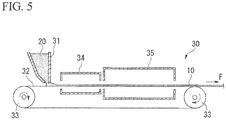
- the porous aluminum sintered compact 10 in the long sheet shape of: 300 mm of width; 1-5 mm of thickness; and 20 m of length is produced, for example, by using the continuous sintering apparatus 30 shown in FIG. 5 .
- This continuous sintering apparatus 30 has: the powder spreading device 31 spreading the aluminum raw material for sintering 20 evenly; the carbon sheet 32 holding the aluminum raw material for sintering 20 supplied from the powder spreading device 31; the transport roller 33 driving the carbon sheet 32; the degreasing furnace 34 removing the binder by heating the aluminum raw material for sintering 20 transported with the carbon sheet 32; and the sintering furnace 35 sintering the binder-free aluminum raw material for sintering 20 by heating.
- the aluminum raw material for sintering 20 is spread toward the upper surface of the carbon sheet 32 from the powder spreading device 31 (the raw material spreading step S03).
- a shape-added processing such as torsion processing, bending processing, and like, is performed on the aluminum fibers 11 in the aluminum substrates 11 used for the aluminum raw material for sintering 20.
- three dimensional and isotropic voids are maintained between the stacked aluminum raw materials for sintering 20.
- the aluminum raw material for sintering 20 which is shaped into a sheet-shape on the carbon sheet 32, is inserted in the degreasing furnace 34 with the carbon sheet 32; and the binder is removed by being heated at a predetermined temperature (the binder removing step S04).
- the binder removing step S04 the aluminum raw material for sintering 20 is maintained at 350°C to 500°C for 0.5 to 5 minutes in the air atmosphere; and the binder in the aluminum raw material for sintering 20 is removed.
- the binder is used only for adhering the titanium powder grains 22 and the magnesium powder grains 23 on the outer surfaces of the aluminum substrates 11 as described above.
- the content amount of the binder is extremely low compared to the viscous compositions; and the binder can be removed sufficiently in a short time.
- the aluminum raw material for sintering 20 free of the binder is inserted in the sintering furnace 35 with the carbon sheet 32 and sintered by being heated at a predetermined temperature (the sintering step S05).
- the sintering step S05 is performed by maintaining the aluminum raw material for sintering 20 at 590°C to 665°C for 0.5 to 60 minutes in an inert gas atmosphere.
- the optimum sintering temperature differs.
- the sintering temperature is set to 590°C, which is the liquidus-line temperature of Al-10mass%Mg, or more.
- the retention time is set to 1 to 20 minutes.
- the optimum temperature differs depending on the content amount of Mg in the aluminum raw material for sintering 20 as described above.
- sintering is performed by heating at the temperature of 590°C to 665°C, which is close to the melting point of the aluminum substrate 11, in any case.
- the aluminum substrates 11 in the aluminum raw material for sintering 20 are melted. Since the oxide films are formed on the surfaces of the aluminum substrates 11, the melted aluminum is held by the oxide film; and the shapes of the aluminum substrates 11 are maintained.
- the oxide files are destroyed by the reaction with titanium; and the melted aluminum inside spouts out.
- the spouted out melted aluminum forms a high-melting point compound by reacting with titanium to be solidified. Because of this, the pillar-shaped protrusions 12 projecting toward the outside are formed on the outer surfaces of the aluminum substrates 11 as shown in FIG. 6 .
- the Ti-Al compound 16 exists on the tip of the pillar-shaped protrusion 12. Growth of the pillar-shaped protrusion 12 is suppressed by the Ti-Al compound 16.
- titanium hydride is used as the titanium powder grains 22
- titanium hydride is decomposed near the temperature of 300°C to 400°C; and the produced titanium reacts with the oxide films on the surfaces of the aluminum substrates 11.
- a part of the oxide films formed on the surfaces of the aluminum substrates is reduced by the magnesium powder grains 23 adhered on the outer surfaces of the aluminum substrates 11; and a large number of the pillar-shaped protrusions 12 are formed. More specifically, it is understood that it is because of thinning of the oxide films by: the magnesium powder grains 23 being sublimed to be dispersed in the oxide films; and reducing the oxide films
- the adjacent the aluminum substrates 11, 11 are bonded each other by being combined integrally in a molten state or being sintered in a solid state through the pillar-shaped protrusions 12 of each. Accordingly, the porous aluminum sintered compact 10, in which the aluminum substrates 11, 11 are bonded each other through the pillar-shaped protrusions 12 as shown in FIG. 1 , is produced.
- the junction 15, in which the aluminum substrates 11, 11 are bonded each other through the pillar-shaped protrusion 12 includes the Ti-Al compound 16 (Al 3 Ti intermetallic compound in the present embodiment) and the Mg oxide 17.
- the junction 15 of the aluminum substrates 11, 11 includes the Ti-Al compound 16.
- the oxide films formed on the surfaces of the aluminum substrates 11 are removed by the Ti-Al compound 16; and the aluminum substrates 11, 11 are bonded properly each other. Therefore, the high-quality porous aluminum sintered compact 10 having sufficient strength can be obtained.
- the growth of the pillar-shaped protrusions 12 is suppressed by the Ti-Al compound 16, spouting out of the melted aluminum into the voids between the aluminum substrates 11, 11 can be suppressed; and the porous aluminum sintered compact 10 having high porosity can be obtained.
- Al 3 Ti exists as the Ti-Al compound 16 in the junction 15 of the aluminum substrates 11, 11 in the present embodiment.
- the oxide films formed on the surfaces of the aluminum substrates 11 are removed reliably; and the aluminum substrates 11, 11 are bonded properly each other. Therefore, strength of the porous aluminum sintered compact 10 can be ensured.
- the junction 15 includes the Mg oxide 17.
- a part of the oxide films formed on the surfaces of the aluminum substrates 11 is reduced; and a large number of the junctions 15 of the aluminum substrates 11, 11 each other can be formed. Accordingly, strength of the porous aluminum sintered compact 10 can be improved significantly.
- the porous aluminum sintered compact 10 has the structure in which the aluminum substrates 11, 11 are bonded each other through the pillar-shaped protrusions 12 formed on the outer surfaces of the aluminum substrates 11.
- the porous aluminum sintered compact 10 having high porosity can be obtained without performing the step of foaming or the like separately. Therefore, the porous aluminum sintered compact 10 of the present embodiment can be produced efficiently at low cost.
- the continuous sintering apparatus 30 is used in the present embodiment.
- the sheet-shaped porous aluminum sintered compact 10 can be produced continuously; and the production efficiency can be improved significantly.
- the content amount of the binder is extremely low compared to the viscous compositions in the present embodiment.
- the binder removing step S04 can be performed in a short time.
- the shrinkage rate during sintering becomes about 1%, for example; and the porous aluminum sintered compact 10 having excellent dimensional accuracy can be obtained.
- the aluminum fibers 11a and the aluminum powder 11b are used as the aluminum substrates 11 in the present embodiment.
- the porosity of the porous aluminum sintered compact 10 can be controlled by adjusting the mixing rates.
- the porosity is set to the range of 30% or more and 90% or less in the porous aluminum sintered compact 10 of the present embodiment.
- the porous aluminum sintered compact 10 having an optimal porosity depending on the application.
- the content amount of the titanium powder grains 22 in the aluminum raw material for sintering 20 is set to 0.01 mass% or more and 20 mass% or less in the present embodiment.
- the pillar-shaped protrusions 12 can be formed with an appropriate distance therebetween on the outer surfaces of the aluminum substrates 11. Accordingly, the porous aluminum sintered compact 10 having sufficient strength and high porosity can be obtained.
- the distance between the titanium powder grains 22, 22 each other adhered on the outer surfaces of the aluminum substrates 11 is set to the range of 5 ⁇ m or more and 100 ⁇ m or less in the present embodiment.
- the distance between the pillar-shaped protrusions 12 is set appropriately. Accordingly, the porous aluminum sintered compact 10 having sufficient strength and high porosity can be obtained.
- the content amount of the magnesium powder grains 23 in the aluminum raw material for sintering 20 is set to 0.01 mass% or more and 5 mass% or less in the present embodiment.
- the oxide films on the surfaces of the aluminum substrates 11 at an appropriate extent a large number of the pillar-shaped protrusions 12 can be formed with an appropriate distance therebetween. Accordingly, the porous aluminum sintered compact 10 having sufficient strength and high porosity can be obtained.
- the fiber diameter of the aluminum fiber 11a which is the aluminum substrate 11, is set to the range of 40 ⁇ m or more and 500 ⁇ m or less; and the grain size of the aluminum powder 11b is set to the range of 20 ⁇ m or more and 300 ⁇ m or less in the present embodiment.
- the grain size of the titanium powder grains 22 is set to the range of 1 ⁇ m or more and 50 ⁇ m or less; and the grain size of the magnesium powder grains 23 is set to the range of 20 ⁇ m or more and 150 ⁇ m or less. Therefore, the titanium powder grains 22 and the magnesium powder grains 23 are dispersedly adhered on the outer surfaces of the aluminum substrates 11 (the aluminum fibers 11a and the aluminum powder 11b) reliably.
- the aluminum fibers 11a and the aluminum powder 11b are used as the aluminum substrates 11; and the ratio of the aluminum powder 11b relative to the aluminum substrates 11 is set to 15 mass% or less in the present embodiment.
- the porous aluminum sintered compact 10 with high porosity can be obtained.
- the aluminum fibers 11a; and any one or both of the Mg powder and Mg alloy powder 23, are mixed at room temperature.
- a binder solution is sprayed on.
- the binder what is burned and decomposed during heating at 500°C in the air is preferable. More specifically, using an acrylic resin or a cellulose-based polymer material is preferable.
- various solvents such as the water-based, alcohol-based, and organic-based solvents can be used as the solvent of the binder.
- the aluminum fibers 11a and the Mg powder 23 are mixed by various mixing machine, such as an automatic mortar, a pan type rolling granulator, a shaker mixer, a pot mill, a high-speed mixer, a V-shaped mixer, and the like, while they are fluidized.
- various mixing machine such as an automatic mortar, a pan type rolling granulator, a shaker mixer, a pot mill, a high-speed mixer, a V-shaped mixer, and the like, while they are fluidized.
- the Mg powder and the Mg alloy powder 23 are dispersedly adhered on the outer surfaces of the aluminum fibers 11a; and the aluminum raw material for sintering 20 in the present embodiment is produced.
- the porous aluminum sintered compact 10 in the long sheet shape of: 300 mm of width; 1-5 mm of thickness; and 20 m of length is produced, for example, by using a continuous sintering apparatus or the like for example.
- the aluminum raw material for sintering 20 is spread toward the upper surface of the carbon sheet from a raw material spreading apparatus; the aluminum raw material for sintering 20 is stacked; and the aluminum raw material for sintering 20 stacked on the carbon sheet is shaped into a sheet-shape. At this time, voids are formed between the aluminum fibers 11a in the aluminum raw material for sintering 20.
- the aluminum fibers 11a are stacked in such a way that the bulk density after filling becomes 50% of the true density of the aluminum fibers to maintain three-dimensional and isotropic voids between the aluminum fibers 11a in stacking.
- the aluminum raw material for sintering 20 which is shaped into the sheet-shape on the carbon sheet, is inserted in the degreasing furnace; and the binder is removed by being heated at a predetermined temperature.
- the aluminum raw material for sintering is maintained at 350°C to 500°C for 0.5 to 5 minutes in the air atmosphere; and the binder in the aluminum raw material for sintering is removed.
- the binder is used only for adhering the Mg powder and the Mg alloy powder 23 on the outer surfaces of the aluminum fibers 11a.
- the content amount of the binder is extremely low compared to the viscous compositions; and the binder can be removed sufficiently in a short time.
- the aluminum raw material for sintering 20 free of the binder is inserted in the sintering furnace with the carbon sheet and sintered by being heated at a predetermined temperature.
- the sintering is performed by maintaining the aluminum raw material for sintering at 590°C to 665°C for 0.5 to 60 minutes in an inert gas atmosphere, for example.
- the optimum sintering temperature differs.
- the sintering temperature is set to 590°C, which is the liquidus-line temperature of Al-10mass%Mg, or more.
- the retention time is set to 1 to 20 minutes.
- Mg functions as a reducing agent for the oxide films of Al 2 O 3 ; the oxide films are destroyed; and formation of sintered bonding is stimulated.
- Mg which is adhered on the surfaces of the aluminum fibers, reacting locally with the aluminum fibers, the melting point lowering effect is obtained locally in the vicinity of the adhering parts.
- the liquid phase is formed at an even lower temperature than the melting point of the pure aluminum fibers or the aluminum alloy fibers; and sintering is stimulated to improve strength compared to the case free of Mg addition.
- Mg diffuses into the aluminum fibers gradually with progression of sintering, Mg exists in solid solution or in the form of Mg oxide in the finally obtained porous aluminum sintered compact.
- porous aluminum sintered compact is continuously produced by using the continuous sintering apparatus shown in FIG. 5 .
- the present invention is not limited by the description, and the porous aluminum sintered compact may be produced by using other producing apparatus
- the sheet-shaped porous aluminum sintered compacts are explained in the present embodiment.
- the present invention is not particularly limited by the description, and it may be the bulk-shaped porous aluminum sintered compact produced by the production process shown in FIG. 7 , for example.
- the aluminum raw material for sintering 20 is spread to bulk fill (the raw material spreading step) on the carbon-made container 132 from the powder spreader 131 spreading the aluminum raw material for sintering 20. Then, the container 132 is inserted in the degreasing furnace 134; and the binder is removed by heating under air atmosphere (the binder removing step). Then, the container is inserted in the sintering furnace 135; and heated to and retained at 590°C to 665°C under an Ar atmosphere to obtain the bulk-shaped porous aluminum sintered compact 110.
- the bulk-shaped porous aluminum sintered compact 110 can be taken out from the carbon-made container 132 relatively easily, since a carbon-made container having excellent mold releasing characteristics is used as the carbon-made container 132; and the content is shrunk in the shrinkage rate about 1% during sintering.
- the aluminum raw materials for sintering were prepared.
- the porous aluminum sintered compacts having the dimension of: 30 mm of width; 200 mm of length; and 5 mm of thickness, were produced. More specifically, the sintering step was performed in the condition of: in the highly-pure argon atmosphere; at a sintering temperature appropriately selected based on each of aluminum raw materials between 590°C to 655°C; and the retention time of 15 minutes for each.
- the true density (g/cm 3 ) was measured by the water method with the precision balance.
- the tensile strength of the obtained porous aluminum sintered compacts was measured by the pulling method.
Landscapes
- Chemical & Material Sciences (AREA)
- Engineering & Computer Science (AREA)
- Mechanical Engineering (AREA)
- Materials Engineering (AREA)
- Metallurgy (AREA)
- Organic Chemistry (AREA)
- Manufacturing & Machinery (AREA)
- Powder Metallurgy (AREA)
- Manufacture Of Alloys Or Alloy Compounds (AREA)
Applications Claiming Priority (3)
| Application Number | Priority Date | Filing Date | Title |
|---|---|---|---|
| JP2014102834 | 2014-05-16 | ||
| JP2015099292A JP6488875B2 (ja) | 2014-05-16 | 2015-05-14 | 多孔質アルミニウム焼結体及び多孔質アルミニウム焼結体の製造方法 |
| PCT/JP2015/064179 WO2015174541A1 (ja) | 2014-05-16 | 2015-05-18 | 多孔質アルミニウム焼結体及び多孔質アルミニウム焼結体の製造方法 |
Publications (3)
| Publication Number | Publication Date |
|---|---|
| EP3144083A1 true EP3144083A1 (de) | 2017-03-22 |
| EP3144083A4 EP3144083A4 (de) | 2018-01-03 |
| EP3144083B1 EP3144083B1 (de) | 2020-01-15 |
Family
ID=54480075
Family Applications (1)
| Application Number | Title | Priority Date | Filing Date |
|---|---|---|---|
| EP15792389.7A Active EP3144083B1 (de) | 2014-05-16 | 2015-05-18 | Poröser aluminiumsinterkörper und verfahren zur herstellung eines porösen aluminiumsinterkörpers |
Country Status (5)
| Country | Link |
|---|---|
| US (1) | US10981228B2 (de) |
| EP (1) | EP3144083B1 (de) |
| JP (1) | JP6488875B2 (de) |
| CN (1) | CN106132598B (de) |
| WO (1) | WO2015174541A1 (de) |
Families Citing this family (7)
| Publication number | Priority date | Publication date | Assignee | Title |
|---|---|---|---|---|
| JP6477254B2 (ja) | 2014-05-30 | 2019-03-06 | 三菱マテリアル株式会社 | 多孔質アルミニウム複合体及び多孔質アルミニウム複合体の製造方法 |
| JP6237500B2 (ja) * | 2014-07-02 | 2017-11-29 | 三菱マテリアル株式会社 | 多孔質アルミニウム熱交換部材 |
| JP6593875B2 (ja) * | 2014-11-28 | 2019-10-23 | 国立大学法人信州大学 | 多孔質材料及びその製造方法 |
| US11420071B2 (en) | 2017-04-11 | 2022-08-23 | Peaklogic, Inc. | Minimum neuronal activation threshold transcranial magnetic stimulation at personalized resonant frequency |
| JP2021143366A (ja) * | 2020-03-11 | 2021-09-24 | 三菱マテリアル株式会社 | 熱交換用パイプ及びその製造方法 |
| CN111774574B (zh) * | 2020-07-20 | 2022-08-30 | 桂林电子科技大学 | Al-含Bi化合物多孔块体制氢材料的制备及应用 |
| CN114613945B (zh) * | 2022-04-02 | 2023-06-23 | 北京师范大学 | 一种锂离子电池正极的制备方法 |
Family Cites Families (42)
| Publication number | Priority date | Publication date | Assignee | Title |
|---|---|---|---|---|
| US3301671A (en) | 1964-03-03 | 1967-01-31 | Alloys Res & Mfg Corp | Aluminous sintered parts and techniques for fabricating same |
| BE788786A (fr) * | 1971-09-13 | 1973-03-13 | Eastman Kodak Co | Procede de polymerisation en emulsion et compositions obtenues |
| JPS5677301A (en) * | 1979-11-27 | 1981-06-25 | N D C Kk | Sintering method of al or its alloy powder |
| JPS56149363A (en) * | 1980-04-15 | 1981-11-19 | Nippon Dia Clevite Co | Manufacture of porous sintered body such as aluminum |
| JPH03110045A (ja) | 1989-09-21 | 1991-05-10 | Toyobo Co Ltd | ふくらみ部を有する金属繊維およびその製造方法 |
| US5098469A (en) | 1991-09-12 | 1992-03-24 | General Motors Corporation | Powder metal process for producing multiphase NI-AL-TI intermetallic alloys |
| JPH06330215A (ja) | 1993-05-25 | 1994-11-29 | Nippon Haiburitsudo Technol Kk | 低密度多孔質アルミニウム合金焼結体とその製造方法 |
| JP3568052B2 (ja) * | 1994-12-15 | 2004-09-22 | 住友電気工業株式会社 | 金属多孔体、その製造方法及びそれを用いた電池用極板 |
| JPH08325661A (ja) | 1995-05-31 | 1996-12-10 | Ndc Co Ltd | 多孔質アルミニウム焼結材 |
| JPH08325662A (ja) | 1995-05-31 | 1996-12-10 | Ndc Co Ltd | 多孔質アルミニウム焼結材 |
| JPH08325660A (ja) | 1995-05-31 | 1996-12-10 | Ndc Co Ltd | 多孔質アルミニウム焼結材 |
| CN1373233A (zh) * | 2001-02-28 | 2002-10-09 | Ndc工程技术株式会社 | 多孔质a1烧结材料的制造方法 |
| US6823928B2 (en) | 2002-09-27 | 2004-11-30 | University Of Queensland | Infiltrated aluminum preforms |
| JP4303649B2 (ja) | 2004-06-24 | 2009-07-29 | 日立粉末冶金株式会社 | 焼結アルミニウム部材の原料用粉末混合物 |
| JP2006028616A (ja) | 2004-07-20 | 2006-02-02 | Toho Titanium Co Ltd | 多孔質焼結体およびその製造方法 |
| JP2008020864A (ja) | 2006-07-14 | 2008-01-31 | Central Glass Co Ltd | 吸音性不織布シート |
| AU2007283448A1 (en) * | 2006-08-07 | 2008-02-14 | The University Of Queensland | Metal injection moulding method |
| WO2009055452A2 (en) * | 2007-10-24 | 2009-04-30 | Mott Corporation | Sintered fiber filter |
| JP5182648B2 (ja) * | 2008-03-18 | 2013-04-17 | 日立金属株式会社 | 多孔質アルミニウム焼結体の製造方法 |
| JP2009228025A (ja) * | 2008-03-19 | 2009-10-08 | Ykk Corp | 前駆体及び発泡金属成形体、並びにそれらの製造方法 |
| JP2010116623A (ja) | 2008-11-14 | 2010-05-27 | Toyota Industries Corp | 金属発泡体および金属発泡体の製造方法 |
| JP5402380B2 (ja) | 2009-03-30 | 2014-01-29 | 三菱マテリアル株式会社 | アルミニウム多孔質焼結体の製造方法 |
| CN102438778B (zh) | 2009-03-30 | 2014-10-29 | 三菱综合材料株式会社 | 铝多孔烧结体的制造方法和铝多孔烧结体 |
| JP5428546B2 (ja) | 2009-06-04 | 2014-02-26 | 三菱マテリアル株式会社 | アルミニウム多孔質焼結体を有するアルミニウム複合体の製造方法 |
| JP5338533B2 (ja) | 2009-07-13 | 2013-11-13 | 三菱マテリアル株式会社 | 電気二重層型キャパシタ用電極およびその製造方法 |
| JP5407663B2 (ja) * | 2009-08-27 | 2014-02-05 | 三菱マテリアル株式会社 | 非水電解質二次電池用電極およびその製造方法 |
| JP5310450B2 (ja) | 2009-09-30 | 2013-10-09 | 三菱マテリアル株式会社 | 非水系電気化学セルの集電体およびそれを用いた電極 |
| JP5526941B2 (ja) | 2010-03-31 | 2014-06-18 | 三菱マテリアル株式会社 | アルミニウム多孔質焼結体の製造方法 |
| JP5560492B2 (ja) | 2010-05-31 | 2014-07-30 | 三菱マテリアル株式会社 | 非水電解質二次電池用集電体およびこれを用いた電極 |
| JP5974424B2 (ja) * | 2010-11-30 | 2016-08-23 | 三菱マテリアル株式会社 | 電気二重層キャパシタ用電極およびこれを用いた電気二重層キャパシタ |
| EP2670508B1 (de) | 2011-02-04 | 2021-08-25 | Entegris, Inc. | Metallischer porösen körper aus gesinterten metallpulvern und metallfasern |
| CN102162052A (zh) * | 2011-03-24 | 2011-08-24 | 中国兵器工业第五二研究所 | 一种高阻尼金属多孔材料及其制备方法 |
| CN102776418B (zh) | 2012-07-24 | 2014-12-17 | 东莞市闻誉实业有限公司 | 增强型泡沫铝合金的制备方法 |
| JP5673707B2 (ja) | 2012-12-27 | 2015-02-18 | 三菱マテリアル株式会社 | アルミニウム多孔体およびその製造方法 |
| JP5594445B1 (ja) | 2013-03-01 | 2014-09-24 | 三菱マテリアル株式会社 | 焼結用アルミニウム原料、焼結用アルミニウム原料の製造方法及び多孔質アルミニウム焼結体の製造方法 |
| JP5633658B2 (ja) | 2013-03-01 | 2014-12-03 | 三菱マテリアル株式会社 | 多孔質アルミニウム焼結体 |
| JP5825311B2 (ja) | 2013-09-06 | 2015-12-02 | 三菱マテリアル株式会社 | アルミニウム多孔質焼結体 |
| CN103667762B (zh) * | 2013-11-26 | 2016-09-14 | 西南科技大学 | 一种低密度多孔金属材料的制备方法 |
| JP6488876B2 (ja) | 2014-05-16 | 2019-03-27 | 三菱マテリアル株式会社 | 多孔質アルミニウム焼結体及び多孔質アルミニウム焼結体の製造方法 |
| JP6477254B2 (ja) | 2014-05-30 | 2019-03-06 | 三菱マテリアル株式会社 | 多孔質アルミニウム複合体及び多孔質アルミニウム複合体の製造方法 |
| JP6237500B2 (ja) | 2014-07-02 | 2017-11-29 | 三菱マテリアル株式会社 | 多孔質アルミニウム熱交換部材 |
| JP6405892B2 (ja) | 2014-10-30 | 2018-10-17 | 三菱マテリアル株式会社 | 多孔質アルミニウム焼結体及び多孔質アルミニウム焼結体の製造方法 |
-
2015
- 2015-05-14 JP JP2015099292A patent/JP6488875B2/ja not_active Expired - Fee Related
- 2015-05-18 EP EP15792389.7A patent/EP3144083B1/de active Active
- 2015-05-18 CN CN201580013707.9A patent/CN106132598B/zh not_active Expired - Fee Related
- 2015-05-18 US US15/306,388 patent/US10981228B2/en not_active Expired - Fee Related
- 2015-05-18 WO PCT/JP2015/064179 patent/WO2015174541A1/ja not_active Ceased
Also Published As
| Publication number | Publication date |
|---|---|
| US20170043398A1 (en) | 2017-02-16 |
| JP6488875B2 (ja) | 2019-03-27 |
| JP2015232173A (ja) | 2015-12-24 |
| CN106132598B (zh) | 2019-04-19 |
| WO2015174541A1 (ja) | 2015-11-19 |
| EP3144083B1 (de) | 2020-01-15 |
| US10981228B2 (en) | 2021-04-20 |
| CN106132598A (zh) | 2016-11-16 |
| EP3144083A4 (de) | 2018-01-03 |
Similar Documents
| Publication | Publication Date | Title |
|---|---|---|
| EP3144083B1 (de) | Poröser aluminiumsinterkörper und verfahren zur herstellung eines porösen aluminiumsinterkörpers | |
| EP3144082A1 (de) | Poröser aluminiumsinterkörper und verfahren zur herstellung eines porösen aluminiumsinterkörpers | |
| EP3150305B1 (de) | Poröser aluminiumverbundwerkstoff und verfahren zur herstellung des porösen aluminiumverbundwerkstoffs | |
| Kotadia et al. | Intermetallic compound growth suppression at high temperature in SAC solders with Zn addition on Cu and Ni–P substrates | |
| US9669462B2 (en) | Porous aluminum sintered compact | |
| US10035187B2 (en) | Aluminum material for sintering, method for producing aluminum material for sintering, and method for producing porous aluminum sintered compact | |
| US20130068365A1 (en) | Dispersion, method for producing same, and use thereof | |
| JP6459726B2 (ja) | 多孔質アルミニウム焼結体、多孔質アルミニウム複合部材、多孔質アルミニウム焼結体の製造方法、多孔質アルミニウム複合部材の製造方法 | |
| US20140238191A1 (en) | Magnesium-based alloy powder and magnesium-based alloy molded article | |
| EP3213839B1 (de) | Poröser aluminiumsinterkörper und verfahren zur herstellung eines porösen aluminiumsinterkörpers | |
| JP4651335B2 (ja) | チタンインゴットの製造方法 | |
| JP2019090065A (ja) | アルミニウム系多孔質部材及びその製造方法 | |
| JP6459725B2 (ja) | 多孔質アルミニウム焼結体、多孔質アルミニウム複合部材、多孔質アルミニウム焼結体の製造方法、多孔質アルミニウム複合部材の製造方法 | |
| JP6439550B2 (ja) | 多孔質アルミニウム焼結体、多孔質アルミニウム複合部材、多孔質アルミニウム焼結体の製造方法、多孔質アルミニウム複合部材の製造方法 | |
| HK1184746A (en) | Dispersion, method for producing same, and use thereof |
Legal Events
| Date | Code | Title | Description |
|---|---|---|---|
| STAA | Information on the status of an ep patent application or granted ep patent |
Free format text: STATUS: THE INTERNATIONAL PUBLICATION HAS BEEN MADE |
|
| PUAI | Public reference made under article 153(3) epc to a published international application that has entered the european phase |
Free format text: ORIGINAL CODE: 0009012 |
|
| STAA | Information on the status of an ep patent application or granted ep patent |
Free format text: STATUS: REQUEST FOR EXAMINATION WAS MADE |
|
| 17P | Request for examination filed |
Effective date: 20161020 |
|
| AK | Designated contracting states |
Kind code of ref document: A1 Designated state(s): AL AT BE BG CH CY CZ DE DK EE ES FI FR GB GR HR HU IE IS IT LI LT LU LV MC MK MT NL NO PL PT RO RS SE SI SK SM TR |
|
| AX | Request for extension of the european patent |
Extension state: BA ME |
|
| DAV | Request for validation of the european patent (deleted) | ||
| DAX | Request for extension of the european patent (deleted) | ||
| A4 | Supplementary search report drawn up and despatched |
Effective date: 20171204 |
|
| RIC1 | Information provided on ipc code assigned before grant |
Ipc: C22C 32/00 20060101ALI20171124BHEP Ipc: C22C 1/04 20060101ALI20171124BHEP Ipc: C22C 1/08 20060101ALI20171124BHEP Ipc: B22F 3/11 20060101AFI20171124BHEP Ipc: C22C 47/14 20060101ALI20171124BHEP |
|
| STAA | Information on the status of an ep patent application or granted ep patent |
Free format text: STATUS: EXAMINATION IS IN PROGRESS |
|
| 17Q | First examination report despatched |
Effective date: 20181130 |
|
| RAP1 | Party data changed (applicant data changed or rights of an application transferred) |
Owner name: MITSUBISHI MATERIALS CORPORATION |
|
| GRAP | Despatch of communication of intention to grant a patent |
Free format text: ORIGINAL CODE: EPIDOSNIGR1 |
|
| STAA | Information on the status of an ep patent application or granted ep patent |
Free format text: STATUS: GRANT OF PATENT IS INTENDED |
|
| INTG | Intention to grant announced |
Effective date: 20190828 |
|
| GRAS | Grant fee paid |
Free format text: ORIGINAL CODE: EPIDOSNIGR3 |
|
| GRAA | (expected) grant |
Free format text: ORIGINAL CODE: 0009210 |
|
| STAA | Information on the status of an ep patent application or granted ep patent |
Free format text: STATUS: THE PATENT HAS BEEN GRANTED |
|
| AK | Designated contracting states |
Kind code of ref document: B1 Designated state(s): AL AT BE BG CH CY CZ DE DK EE ES FI FR GB GR HR HU IE IS IT LI LT LU LV MC MK MT NL NO PL PT RO RS SE SI SK SM TR |
|
| REG | Reference to a national code |
Ref country code: CH Ref legal event code: EP Ref country code: GB Ref legal event code: FG4D |
|
| REG | Reference to a national code |
Ref country code: IE Ref legal event code: FG4D |
|
| REG | Reference to a national code |
Ref country code: DE Ref legal event code: R096 Ref document number: 602015045691 Country of ref document: DE |
|
| REG | Reference to a national code |
Ref country code: AT Ref legal event code: REF Ref document number: 1224715 Country of ref document: AT Kind code of ref document: T Effective date: 20200215 |
|
| REG | Reference to a national code |
Ref country code: NL Ref legal event code: MP Effective date: 20200115 |
|
| REG | Reference to a national code |
Ref country code: LT Ref legal event code: MG4D |
|
| PG25 | Lapsed in a contracting state [announced via postgrant information from national office to epo] |
Ref country code: NL Free format text: LAPSE BECAUSE OF FAILURE TO SUBMIT A TRANSLATION OF THE DESCRIPTION OR TO PAY THE FEE WITHIN THE PRESCRIBED TIME-LIMIT Effective date: 20200115 Ref country code: PT Free format text: LAPSE BECAUSE OF FAILURE TO SUBMIT A TRANSLATION OF THE DESCRIPTION OR TO PAY THE FEE WITHIN THE PRESCRIBED TIME-LIMIT Effective date: 20200607 Ref country code: NO Free format text: LAPSE BECAUSE OF FAILURE TO SUBMIT A TRANSLATION OF THE DESCRIPTION OR TO PAY THE FEE WITHIN THE PRESCRIBED TIME-LIMIT Effective date: 20200415 Ref country code: RS Free format text: LAPSE BECAUSE OF FAILURE TO SUBMIT A TRANSLATION OF THE DESCRIPTION OR TO PAY THE FEE WITHIN THE PRESCRIBED TIME-LIMIT Effective date: 20200115 Ref country code: FI Free format text: LAPSE BECAUSE OF FAILURE TO SUBMIT A TRANSLATION OF THE DESCRIPTION OR TO PAY THE FEE WITHIN THE PRESCRIBED TIME-LIMIT Effective date: 20200115 |
|
| PG25 | Lapsed in a contracting state [announced via postgrant information from national office to epo] |
Ref country code: LV Free format text: LAPSE BECAUSE OF FAILURE TO SUBMIT A TRANSLATION OF THE DESCRIPTION OR TO PAY THE FEE WITHIN THE PRESCRIBED TIME-LIMIT Effective date: 20200115 Ref country code: SE Free format text: LAPSE BECAUSE OF FAILURE TO SUBMIT A TRANSLATION OF THE DESCRIPTION OR TO PAY THE FEE WITHIN THE PRESCRIBED TIME-LIMIT Effective date: 20200115 Ref country code: HR Free format text: LAPSE BECAUSE OF FAILURE TO SUBMIT A TRANSLATION OF THE DESCRIPTION OR TO PAY THE FEE WITHIN THE PRESCRIBED TIME-LIMIT Effective date: 20200115 Ref country code: BG Free format text: LAPSE BECAUSE OF FAILURE TO SUBMIT A TRANSLATION OF THE DESCRIPTION OR TO PAY THE FEE WITHIN THE PRESCRIBED TIME-LIMIT Effective date: 20200415 Ref country code: IS Free format text: LAPSE BECAUSE OF FAILURE TO SUBMIT A TRANSLATION OF THE DESCRIPTION OR TO PAY THE FEE WITHIN THE PRESCRIBED TIME-LIMIT Effective date: 20200515 Ref country code: GR Free format text: LAPSE BECAUSE OF FAILURE TO SUBMIT A TRANSLATION OF THE DESCRIPTION OR TO PAY THE FEE WITHIN THE PRESCRIBED TIME-LIMIT Effective date: 20200416 |
|
| REG | Reference to a national code |
Ref country code: DE Ref legal event code: R097 Ref document number: 602015045691 Country of ref document: DE |
|
| PG25 | Lapsed in a contracting state [announced via postgrant information from national office to epo] |
Ref country code: LT Free format text: LAPSE BECAUSE OF FAILURE TO SUBMIT A TRANSLATION OF THE DESCRIPTION OR TO PAY THE FEE WITHIN THE PRESCRIBED TIME-LIMIT Effective date: 20200115 Ref country code: CZ Free format text: LAPSE BECAUSE OF FAILURE TO SUBMIT A TRANSLATION OF THE DESCRIPTION OR TO PAY THE FEE WITHIN THE PRESCRIBED TIME-LIMIT Effective date: 20200115 Ref country code: DK Free format text: LAPSE BECAUSE OF FAILURE TO SUBMIT A TRANSLATION OF THE DESCRIPTION OR TO PAY THE FEE WITHIN THE PRESCRIBED TIME-LIMIT Effective date: 20200115 Ref country code: RO Free format text: LAPSE BECAUSE OF FAILURE TO SUBMIT A TRANSLATION OF THE DESCRIPTION OR TO PAY THE FEE WITHIN THE PRESCRIBED TIME-LIMIT Effective date: 20200115 Ref country code: SM Free format text: LAPSE BECAUSE OF FAILURE TO SUBMIT A TRANSLATION OF THE DESCRIPTION OR TO PAY THE FEE WITHIN THE PRESCRIBED TIME-LIMIT Effective date: 20200115 Ref country code: EE Free format text: LAPSE BECAUSE OF FAILURE TO SUBMIT A TRANSLATION OF THE DESCRIPTION OR TO PAY THE FEE WITHIN THE PRESCRIBED TIME-LIMIT Effective date: 20200115 Ref country code: ES Free format text: LAPSE BECAUSE OF FAILURE TO SUBMIT A TRANSLATION OF THE DESCRIPTION OR TO PAY THE FEE WITHIN THE PRESCRIBED TIME-LIMIT Effective date: 20200115 Ref country code: SK Free format text: LAPSE BECAUSE OF FAILURE TO SUBMIT A TRANSLATION OF THE DESCRIPTION OR TO PAY THE FEE WITHIN THE PRESCRIBED TIME-LIMIT Effective date: 20200115 |
|
| REG | Reference to a national code |
Ref country code: AT Ref legal event code: MK05 Ref document number: 1224715 Country of ref document: AT Kind code of ref document: T Effective date: 20200115 |
|
| PLBE | No opposition filed within time limit |
Free format text: ORIGINAL CODE: 0009261 |
|
| STAA | Information on the status of an ep patent application or granted ep patent |
Free format text: STATUS: NO OPPOSITION FILED WITHIN TIME LIMIT |
|
| 26N | No opposition filed |
Effective date: 20201016 |
|
| PG25 | Lapsed in a contracting state [announced via postgrant information from national office to epo] |
Ref country code: MC Free format text: LAPSE BECAUSE OF FAILURE TO SUBMIT A TRANSLATION OF THE DESCRIPTION OR TO PAY THE FEE WITHIN THE PRESCRIBED TIME-LIMIT Effective date: 20200115 Ref country code: AT Free format text: LAPSE BECAUSE OF FAILURE TO SUBMIT A TRANSLATION OF THE DESCRIPTION OR TO PAY THE FEE WITHIN THE PRESCRIBED TIME-LIMIT Effective date: 20200115 Ref country code: IT Free format text: LAPSE BECAUSE OF FAILURE TO SUBMIT A TRANSLATION OF THE DESCRIPTION OR TO PAY THE FEE WITHIN THE PRESCRIBED TIME-LIMIT Effective date: 20200115 Ref country code: LI Free format text: LAPSE BECAUSE OF NON-PAYMENT OF DUE FEES Effective date: 20200531 Ref country code: CH Free format text: LAPSE BECAUSE OF NON-PAYMENT OF DUE FEES Effective date: 20200531 |
|
| PG25 | Lapsed in a contracting state [announced via postgrant information from national office to epo] |
Ref country code: PL Free format text: LAPSE BECAUSE OF FAILURE TO SUBMIT A TRANSLATION OF THE DESCRIPTION OR TO PAY THE FEE WITHIN THE PRESCRIBED TIME-LIMIT Effective date: 20200115 Ref country code: SI Free format text: LAPSE BECAUSE OF FAILURE TO SUBMIT A TRANSLATION OF THE DESCRIPTION OR TO PAY THE FEE WITHIN THE PRESCRIBED TIME-LIMIT Effective date: 20200115 |
|
| REG | Reference to a national code |
Ref country code: BE Ref legal event code: MM Effective date: 20200531 |
|
| PG25 | Lapsed in a contracting state [announced via postgrant information from national office to epo] |
Ref country code: LU Free format text: LAPSE BECAUSE OF NON-PAYMENT OF DUE FEES Effective date: 20200518 |
|
| PG25 | Lapsed in a contracting state [announced via postgrant information from national office to epo] |
Ref country code: IE Free format text: LAPSE BECAUSE OF NON-PAYMENT OF DUE FEES Effective date: 20200518 |
|
| PG25 | Lapsed in a contracting state [announced via postgrant information from national office to epo] |
Ref country code: BE Free format text: LAPSE BECAUSE OF NON-PAYMENT OF DUE FEES Effective date: 20200531 |
|
| PG25 | Lapsed in a contracting state [announced via postgrant information from national office to epo] |
Ref country code: TR Free format text: LAPSE BECAUSE OF FAILURE TO SUBMIT A TRANSLATION OF THE DESCRIPTION OR TO PAY THE FEE WITHIN THE PRESCRIBED TIME-LIMIT Effective date: 20200115 Ref country code: MT Free format text: LAPSE BECAUSE OF FAILURE TO SUBMIT A TRANSLATION OF THE DESCRIPTION OR TO PAY THE FEE WITHIN THE PRESCRIBED TIME-LIMIT Effective date: 20200115 Ref country code: CY Free format text: LAPSE BECAUSE OF FAILURE TO SUBMIT A TRANSLATION OF THE DESCRIPTION OR TO PAY THE FEE WITHIN THE PRESCRIBED TIME-LIMIT Effective date: 20200115 |
|
| PG25 | Lapsed in a contracting state [announced via postgrant information from national office to epo] |
Ref country code: MK Free format text: LAPSE BECAUSE OF FAILURE TO SUBMIT A TRANSLATION OF THE DESCRIPTION OR TO PAY THE FEE WITHIN THE PRESCRIBED TIME-LIMIT Effective date: 20200115 Ref country code: AL Free format text: LAPSE BECAUSE OF FAILURE TO SUBMIT A TRANSLATION OF THE DESCRIPTION OR TO PAY THE FEE WITHIN THE PRESCRIBED TIME-LIMIT Effective date: 20200115 |
|
| PGFP | Annual fee paid to national office [announced via postgrant information from national office to epo] |
Ref country code: FR Payment date: 20230526 Year of fee payment: 9 Ref country code: DE Payment date: 20230519 Year of fee payment: 9 |
|
| PGFP | Annual fee paid to national office [announced via postgrant information from national office to epo] |
Ref country code: GB Payment date: 20230524 Year of fee payment: 9 |
|
| REG | Reference to a national code |
Ref country code: DE Ref legal event code: R119 Ref document number: 602015045691 Country of ref document: DE |
|
| GBPC | Gb: european patent ceased through non-payment of renewal fee |
Effective date: 20240518 |
|
| PG25 | Lapsed in a contracting state [announced via postgrant information from national office to epo] |
Ref country code: DE Free format text: LAPSE BECAUSE OF NON-PAYMENT OF DUE FEES Effective date: 20241203 |
|
| PG25 | Lapsed in a contracting state [announced via postgrant information from national office to epo] |
Ref country code: FR Free format text: LAPSE BECAUSE OF NON-PAYMENT OF DUE FEES Effective date: 20240531 |
|
| PG25 | Lapsed in a contracting state [announced via postgrant information from national office to epo] |
Ref country code: GB Free format text: LAPSE BECAUSE OF NON-PAYMENT OF DUE FEES Effective date: 20240518 |