EP3144098A2 - Système de couplage pour utiliser sur une broche d'une machine-outil - Google Patents
Système de couplage pour utiliser sur une broche d'une machine-outil Download PDFInfo
- Publication number
- EP3144098A2 EP3144098A2 EP16187808.7A EP16187808A EP3144098A2 EP 3144098 A2 EP3144098 A2 EP 3144098A2 EP 16187808 A EP16187808 A EP 16187808A EP 3144098 A2 EP3144098 A2 EP 3144098A2
- Authority
- EP
- European Patent Office
- Prior art keywords
- tool
- coupling
- coupling element
- unit
- interface unit
- Prior art date
- Legal status (The legal status is an assumption and is not a legal conclusion. Google has not performed a legal analysis and makes no representation as to the accuracy of the status listed.)
- Granted
Links
Images


Classifications
-
- B—PERFORMING OPERATIONS; TRANSPORTING
- B23—MACHINE TOOLS; METAL-WORKING NOT OTHERWISE PROVIDED FOR
- B23Q—DETAILS, COMPONENTS, OR ACCESSORIES FOR MACHINE TOOLS, e.g. ARRANGEMENTS FOR COPYING OR CONTROLLING; MACHINE TOOLS IN GENERAL CHARACTERISED BY THE CONSTRUCTION OF PARTICULAR DETAILS OR COMPONENTS; COMBINATIONS OR ASSOCIATIONS OF METAL-WORKING MACHINES, NOT DIRECTED TO A PARTICULAR RESULT
- B23Q1/00—Members which are comprised in the general build-up of a form of machine, particularly relatively large fixed members
- B23Q1/0009—Energy-transferring means or control lines for movable machine parts; Control panels or boxes; Control parts
-
- B—PERFORMING OPERATIONS; TRANSPORTING
- B23—MACHINE TOOLS; METAL-WORKING NOT OTHERWISE PROVIDED FOR
- B23B—TURNING; BORING
- B23B31/00—Chucks; Expansion mandrels; Adaptations thereof for remote control
- B23B31/02—Chucks
- B23B31/24—Chucks characterised by features relating primarily to remote control of the gripping means
- B23B31/28—Chucks characterised by features relating primarily to remote control of the gripping means using electric or magnetic means in the chuck
-
- B—PERFORMING OPERATIONS; TRANSPORTING
- B23—MACHINE TOOLS; METAL-WORKING NOT OTHERWISE PROVIDED FOR
- B23B—TURNING; BORING
- B23B37/00—Boring by making use of vibrations of ultrasonic frequency
-
- B—PERFORMING OPERATIONS; TRANSPORTING
- B23—MACHINE TOOLS; METAL-WORKING NOT OTHERWISE PROVIDED FOR
- B23K—SOLDERING OR UNSOLDERING; WELDING; CLADDING OR PLATING BY SOLDERING OR WELDING; CUTTING BY APPLYING HEAT LOCALLY, e.g. FLAME CUTTING; WORKING BY LASER BEAM
- B23K26/00—Working by laser beam, e.g. welding, cutting or boring
- B23K26/0093—Working by laser beam, e.g. welding, cutting or boring combined with mechanical machining or metal-working covered by other subclasses than B23K
-
- B—PERFORMING OPERATIONS; TRANSPORTING
- B23—MACHINE TOOLS; METAL-WORKING NOT OTHERWISE PROVIDED FOR
- B23K—SOLDERING OR UNSOLDERING; WELDING; CLADDING OR PLATING BY SOLDERING OR WELDING; CUTTING BY APPLYING HEAT LOCALLY, e.g. FLAME CUTTING; WORKING BY LASER BEAM
- B23K26/00—Working by laser beam, e.g. welding, cutting or boring
- B23K26/14—Working by laser beam, e.g. welding, cutting or boring using a fluid stream, e.g. a jet of gas, in conjunction with the laser beam; Nozzles therefor
- B23K26/1462—Nozzles; Features related to nozzles
-
- B—PERFORMING OPERATIONS; TRANSPORTING
- B23—MACHINE TOOLS; METAL-WORKING NOT OTHERWISE PROVIDED FOR
- B23K—SOLDERING OR UNSOLDERING; WELDING; CLADDING OR PLATING BY SOLDERING OR WELDING; CUTTING BY APPLYING HEAT LOCALLY, e.g. FLAME CUTTING; WORKING BY LASER BEAM
- B23K26/00—Working by laser beam, e.g. welding, cutting or boring
- B23K26/34—Laser welding for purposes other than joining
- B23K26/342—Build-up welding
-
- B—PERFORMING OPERATIONS; TRANSPORTING
- B23—MACHINE TOOLS; METAL-WORKING NOT OTHERWISE PROVIDED FOR
- B23P—METAL-WORKING NOT OTHERWISE PROVIDED FOR; COMBINED OPERATIONS; UNIVERSAL MACHINE TOOLS
- B23P23/00—Machines or arrangements of machines for performing specified combinations of different metal-working operations not covered by a single other subclass
- B23P23/04—Machines or arrangements of machines for performing specified combinations of different metal-working operations not covered by a single other subclass for both machining and other metal-working operations
-
- B—PERFORMING OPERATIONS; TRANSPORTING
- B23—MACHINE TOOLS; METAL-WORKING NOT OTHERWISE PROVIDED FOR
- B23Q—DETAILS, COMPONENTS, OR ACCESSORIES FOR MACHINE TOOLS, e.g. ARRANGEMENTS FOR COPYING OR CONTROLLING; MACHINE TOOLS IN GENERAL CHARACTERISED BY THE CONSTRUCTION OF PARTICULAR DETAILS OR COMPONENTS; COMBINATIONS OR ASSOCIATIONS OF METAL-WORKING MACHINES, NOT DIRECTED TO A PARTICULAR RESULT
- B23Q1/00—Members which are comprised in the general build-up of a form of machine, particularly relatively large fixed members
- B23Q1/70—Stationary or movable members for carrying working-spindles for attachment of tools or work
-
- B—PERFORMING OPERATIONS; TRANSPORTING
- B23—MACHINE TOOLS; METAL-WORKING NOT OTHERWISE PROVIDED FOR
- B23Q—DETAILS, COMPONENTS, OR ACCESSORIES FOR MACHINE TOOLS, e.g. ARRANGEMENTS FOR COPYING OR CONTROLLING; MACHINE TOOLS IN GENERAL CHARACTERISED BY THE CONSTRUCTION OF PARTICULAR DETAILS OR COMPONENTS; COMBINATIONS OR ASSOCIATIONS OF METAL-WORKING MACHINES, NOT DIRECTED TO A PARTICULAR RESULT
- B23Q11/00—Accessories fitted to machine tools for keeping tools or parts of the machine in good working condition or for cooling work; Safety devices specially combined with or arranged in, or specially adapted for use in connection with, machine tools
-
- B—PERFORMING OPERATIONS; TRANSPORTING
- B23—MACHINE TOOLS; METAL-WORKING NOT OTHERWISE PROVIDED FOR
- B23Q—DETAILS, COMPONENTS, OR ACCESSORIES FOR MACHINE TOOLS, e.g. ARRANGEMENTS FOR COPYING OR CONTROLLING; MACHINE TOOLS IN GENERAL CHARACTERISED BY THE CONSTRUCTION OF PARTICULAR DETAILS OR COMPONENTS; COMBINATIONS OR ASSOCIATIONS OF METAL-WORKING MACHINES, NOT DIRECTED TO A PARTICULAR RESULT
- B23Q5/00—Driving or feeding mechanisms; Control arrangements therefor
- B23Q5/02—Driving main working members
- B23Q5/04—Driving main working members rotary shafts, e.g. working-spindles
- B23Q5/043—Accessories for spindle drives
-
- B—PERFORMING OPERATIONS; TRANSPORTING
- B23—MACHINE TOOLS; METAL-WORKING NOT OTHERWISE PROVIDED FOR
- B23Q—DETAILS, COMPONENTS, OR ACCESSORIES FOR MACHINE TOOLS, e.g. ARRANGEMENTS FOR COPYING OR CONTROLLING; MACHINE TOOLS IN GENERAL CHARACTERISED BY THE CONSTRUCTION OF PARTICULAR DETAILS OR COMPONENTS; COMBINATIONS OR ASSOCIATIONS OF METAL-WORKING MACHINES, NOT DIRECTED TO A PARTICULAR RESULT
- B23Q5/00—Driving or feeding mechanisms; Control arrangements therefor
- B23Q5/54—Arrangements or details not restricted to group B23Q5/02 or group B23Q5/22 respectively, e.g. control handles
-
- H—ELECTRICITY
- H02—GENERATION; CONVERSION OR DISTRIBUTION OF ELECTRIC POWER
- H02J—ELECTRIC POWER NETWORKS; CIRCUIT ARRANGEMENTS OR SYSTEMS FOR SUPPLYING OR DISTRIBUTING ELECTRIC POWER; SYSTEMS FOR STORING ELECTRIC ENERGY
- H02J50/00—Circuit arrangements or systems for wireless supply or distribution of electric power
- H02J50/10—Circuit arrangements or systems for wireless supply or distribution of electric power using inductive coupling
-
- B—PERFORMING OPERATIONS; TRANSPORTING
- B23—MACHINE TOOLS; METAL-WORKING NOT OTHERWISE PROVIDED FOR
- B23Q—DETAILS, COMPONENTS, OR ACCESSORIES FOR MACHINE TOOLS, e.g. ARRANGEMENTS FOR COPYING OR CONTROLLING; MACHINE TOOLS IN GENERAL CHARACTERISED BY THE CONSTRUCTION OF PARTICULAR DETAILS OR COMPONENTS; COMBINATIONS OR ASSOCIATIONS OF METAL-WORKING MACHINES, NOT DIRECTED TO A PARTICULAR RESULT
- B23Q2220/00—Machine tool components
- B23Q2220/008—Rotatable tool holders coupled in parallel to a non rotating accessory
-
- B—PERFORMING OPERATIONS; TRANSPORTING
- B23—MACHINE TOOLS; METAL-WORKING NOT OTHERWISE PROVIDED FOR
- B23Q—DETAILS, COMPONENTS, OR ACCESSORIES FOR MACHINE TOOLS, e.g. ARRANGEMENTS FOR COPYING OR CONTROLLING; MACHINE TOOLS IN GENERAL CHARACTERISED BY THE CONSTRUCTION OF PARTICULAR DETAILS OR COMPONENTS; COMBINATIONS OR ASSOCIATIONS OF METAL-WORKING MACHINES, NOT DIRECTED TO A PARTICULAR RESULT
- B23Q3/00—Devices holding, supporting, or positioning work or tools, of a kind normally removable from the machine
- B23Q3/155—Arrangements for automatic insertion or removal of tools, e.g. combined with manual handling
-
- G—PHYSICS
- G05—CONTROLLING; REGULATING
- G05B—CONTROL OR REGULATING SYSTEMS IN GENERAL; FUNCTIONAL ELEMENTS OF SUCH SYSTEMS; MONITORING OR TESTING ARRANGEMENTS FOR SUCH SYSTEMS OR ELEMENTS
- G05B2219/00—Program-control systems
- G05B2219/30—Nc systems
- G05B2219/50—Machine tool, machine tool null till machine tool work handling
- G05B2219/50245—Change tools, like laser head and drill having different driving needs
-
- Y—GENERAL TAGGING OF NEW TECHNOLOGICAL DEVELOPMENTS; GENERAL TAGGING OF CROSS-SECTIONAL TECHNOLOGIES SPANNING OVER SEVERAL SECTIONS OF THE IPC; TECHNICAL SUBJECTS COVERED BY FORMER USPC CROSS-REFERENCE ART COLLECTIONS [XRACs] AND DIGESTS
- Y10—TECHNICAL SUBJECTS COVERED BY FORMER USPC
- Y10T—TECHNICAL SUBJECTS COVERED BY FORMER US CLASSIFICATION
- Y10T29/00—Metal working
- Y10T29/51—Plural diverse manufacturing apparatus including means for metal shaping or assembling
- Y10T29/5104—Type of machine
- Y10T29/5105—Drill press
- Y10T29/5107—Drilling and other
-
- Y—GENERAL TAGGING OF NEW TECHNOLOGICAL DEVELOPMENTS; GENERAL TAGGING OF CROSS-SECTIONAL TECHNOLOGIES SPANNING OVER SEVERAL SECTIONS OF THE IPC; TECHNICAL SUBJECTS COVERED BY FORMER USPC CROSS-REFERENCE ART COLLECTIONS [XRACs] AND DIGESTS
- Y10—TECHNICAL SUBJECTS COVERED BY FORMER USPC
- Y10T—TECHNICAL SUBJECTS COVERED BY FORMER US CLASSIFICATION
- Y10T409/00—Gear cutting, milling, or planing
- Y10T409/30—Milling
- Y10T409/309296—Detachable or repositionable tool head
-
- Y—GENERAL TAGGING OF NEW TECHNOLOGICAL DEVELOPMENTS; GENERAL TAGGING OF CROSS-SECTIONAL TECHNOLOGIES SPANNING OVER SEVERAL SECTIONS OF THE IPC; TECHNICAL SUBJECTS COVERED BY FORMER USPC CROSS-REFERENCE ART COLLECTIONS [XRACs] AND DIGESTS
- Y10—TECHNICAL SUBJECTS COVERED BY FORMER USPC
- Y10T—TECHNICAL SUBJECTS COVERED BY FORMER US CLASSIFICATION
- Y10T483/00—Tool changing
- Y10T483/17—Tool changing including machine tool or component
Definitions
- the present invention relates to a system or coupling system for use on a spindle device of a machine tool.
- DE 10 2013 224 649 A1 describes a machine tool with a machine control, a machine frame, a workpiece table, a preferably trained according to a standard tool holder, a plurality of translational and / or rotary axes for adjusting a relative position between the workpiece table and tool holder, a tool magazine for one or more material-removing, in particular cutting tools a tool changing mechanism for automatically transferring tools between the tool holder and the tool magazine, an application welding head insertable into the tool holder, and a bearing device for supporting the deposition welding head beyond the tool holder.
- WO 2014/013247 A2 describes a machine tool configured to direct an energy source to a workpiece through a machining head, the machine tool having a clamping mechanism for temporarily receiving the machining head or other machining head to machine a workpiece.
- the machining head includes one or more directing mechanisms adapted to direct the power source to a workpiece and a machining head receiving means to which one or more media may be supplied to the machining head in use to facilitate machining of the workpiece wherein the machining head receiving means allows the medium or media to be carried by the machining head feed when the machining head is connected to the clamping mechanism.
- the machine tool further comprises at least one mechanism configured to connect a supply receiving device to the processing head receiving device such that when both receiving devices are connected, the medium is supplied to the processing head.
- the machining head used for this processing is additionally supplied with energy on its outside. Due to the different dimensions of the various machining heads, the problem arises that when replacing a machining head for machining by a machining head for build-up welding, the device for the power supply for the machining head, but not for the machining head for build-up welding is required, the machining head for build-up welding in the way and thus prevents an exchange of the two processing heads.
- electrical load tool interface units e.g. find application in ultrasonic processing, and / or in conjunction with material application processing heads for applying material to the conventional material-removing machine tool.
- a further object of the present invention is therefore to provide a coupling system for a machine tool, by means of which different tool interfaces or machining heads can alternately be accommodated on the same machining head receptacle, so that both a material-removing and a machining workpiece machining as well as a MaterialMapende workpiece machining, for example, hardfacing efficient, cost-saving, space-saving and can be performed without restrictions.
- a system for use on a spindle device of a machine tool according to claim 1 or a coupling interface unit for use in such a system according to claim 13 and a power transmission unit for use in such a system according to claim 14 are proposed for achieving the above-mentioned objects .
- the dependent claims or combinations of the dependent claims relate to preferred embodiments.
- a system for use on a spindle device of a machine tool is proposed.
- the system may include an energy transfer unit having a transmit coil unit for non-contact transmission of electrical energy to a receiver coil unit of a tool interface unit.
- the tool interface unit may comprise the receiver coil unit, an electrical load and / or a tool interface section for receiving the tool interface unit on a tool holder of a work spindle of the spindle device.
- a plurality of energy transmission units of different dimensions can be provided for a plurality of tool interface units of different dimensions, wherein preferably a respective coupling element of the energy transmission units is in each case of the same design, for coupling to a single coupling interface unit.
- the system may include a coupling interface unit having an interface body member attachable to the spindle apparatus and a second coupling member, the second coupling member preferably being adapted to be coupled by a releasable connection to a first coupling member of the power transmission unit (s).
- the first and second coupling elements may preferably each comprise one or more plug-in connection elements, preferably such that one or the other a plurality of plug-in connection elements of the first coupling element with the one or more plug-in connection elements of the second coupling element are adapted to produce a releasable plug connection for releasably securing the first coupling element to the second coupling element.
- the first and second coupling elements may preferably each comprise interconnectable electrical contact portions, preferably for establishing an electrical connection between the first and second coupling elements, when the first coupling element is releasably secured to the second coupling element.
- the first coupling element can preferably have electrical line guides which connect the transmitting coil unit of the energy transmission unit, preferably with the electrical contact portions of the first coupling element electrically.
- the second coupling element can preferably have electrical line guides, which electrically connect the electrical contact sections of the second coupling element to electrical connection elements for connecting external electrical line guides arranged on the interface body element of the coupling interface unit.
- the coupling interface unit may preferably comprise an electrically, hydraulically and / or pneumatically controllable locking mechanism for unlocking and / or locking the releasable attachment between the first and second coupling elements.
- the coupling interface unit may preferably comprise electrical, hydraulic and / or pneumatic connection elements arranged on the interface body element for controlling the locking mechanism.
- the interface body element of the coupling interface unit can preferably be fastened to the spindle device by means of a screw connection.
- the system may additionally or alternatively be attached to the machine tool
- Coupling element holder comprising a coupling element receiving for holding the power transmission unit, when the first coupling element of the power transmission unit is decoupled from the second coupling element of the coupling interface unit.
- the system may additionally or alternatively comprise a coupling element adapter with a third coupling element, which is preferably adapted to be coupled to the second coupling element of the coupling interface unit by means of a releasable connection, preferably analogously to the first coupling element of the energy transmission unit first coupling element of the power transmission unit is decoupled from the second coupling element of the coupling interface unit.
- the third and second coupling elements may preferably each comprise one or more plug connection elements, preferably such that the one or more plug connection elements of the third coupling element are preferably arranged with the one or more plug connection elements of the second coupling element for releasable attachment the third coupling element on the second coupling element to produce a releasable plug connection.
- the third coupling element may preferably have a fastening element on the side opposite the plug connection elements for the plug connection with the second coupling element, for releasable attachment to a further fastening element, which can preferably be fastened to a material application processing device that can be received on the tool receptacle of the work spindle of the spindle device ,
- the system may additionally or alternatively comprise the tool interface unit with the receiver coil unit.
- the tool interface unit may continue on a tool interface portion opposite side have a tool receiving portion for receiving a tool.
- the tool interface unit can preferably have as an electrical load a vibration drive, which is preferably designed to drive a vibration of the tool interface unit, in particular preferably in the ultrasonic frequency range.
- a coupling interface unit for use in a system as described above for use on a spindle device of a machine tool.
- the coupling interface unit preferably comprises an interface body member attachable to the spindle apparatus and a second coupling member configured to be coupled by means of a releasable connection to a first coupling element of a power transmission unit of the system.
- an energy transfer unit for use in a system described above for use on a spindle device of a machine tool.
- the energy transmission unit preferably comprises a transmitting coil unit for non-contact transmission of electrical energy to a receiver coil unit of a tool cutting unit having the receiver coil unit, an electrical load and a tool interface section for receiving the tool interface unit on a tool holder of a work spindle of the spindle device, and / or a first coupling element adapted to be coupled by means of a releasable connection to a second coupling element of a coupling interface unit of the system.
- a spindle device for use on a machine tool to which a coupling interface unit according to the aspect described above or a coupling interface unit of a system described above is attached, and a machine tool having such a spindle device.
- a versatile and space-saving and cost-saving tool interface system or coupling interface system for machine tools is provided, in particular space and cost-saving with advantageous synergistic effects in terms of advantageous energy and signal transmission or supply and on advantageously efficient, time-saving and versatile tool change options and Precise tool and processing head alignment can be advantageously used, in particular when used on hybrid machine tools, where, if necessary, in addition to a conventional machining machining further processing options can be combined, such as electrical load tool interface units, e.g. find application in ultrasonic processing, and / or in conjunction with material application processing heads for applying material to the conventional material-removing machine tool.
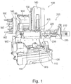
- Fig. 1 shows an exemplary perspective view of a machine tool 100 according to an embodiment of the invention.
- the machine tool 100 includes, by way of example, a machine bed 110 on which, by way of example, a swivel table 120 is arranged with a turntable 130 rotatably mounted on the swivel table 120, on which a workpiece WS is clamped for machining on the machine tool 100.
- the machine tool 100 thus comprises two rotatably controllable axes for rotation of the workpiece WS clamped on the turntable 130, for example a pivot axis oriented horizontally with respect to the machine bed 110 about which the pivot table 120 is pivotable on the machine bed 110, and an in With respect to the pivot table 120 vertically aligned axis of rotation about which the turntable 130 is rotatable on the pivot table 120.
- the rotational axis of the turntable 130 is not absolutely fixed with respect to the machine bed 110, but pivots with the pivoting of the turntable 120 with.
- the machine tool 100 further includes, by way of example, an axle slide assembly having a first axle slide 140 disposed on a rear machine stand of the machine bed 110 and guided on longitudinal axis slide guides fixed to the machine stand. On the longitudinal axis slide guides, the first axis slide 140 can be moved horizontally linearly in the direction of an X-axis of the machine tool 100 by way of example (in FIG Fig. 1 in a horizontal direction from the front to the rear).
- horizontally oriented transverse axis slide guides are arranged on the front side of the first slide carriage 140 on which a second slide slide 150 exemplarily in the direction of a Y-axis of the machine tool 100 horizontally and transversely to the direction of the X-axis of the first slide carriage 140th linearly movable (in Fig. 1 in a horizontal left-to-right direction).
- a spindle head with a spindle head housing 160 is held.
- the spindle head is linearly linearly displaceable in the direction of a Z axis of the machine tool 100, for example. in particular, for example, respectively transversely or perpendicular to the directions of the X and Y axes.
- a work spindle of a spindle device 170 is arranged, whose spindle axis is oriented by way of example vertically and in particular parallel to the direction of the Z axis.
- a control device not shown, of a numerical machine tool control, possibly with CNC control unit and / or PLC control unit, possibly based on NC programs and / or manually on a control panel of the machine tool 100 entered control commands.
- all three linear axes can move independently of one another or simultaneously the tool received on the work spindle of the spindle device 170 actively with respect to the position of the workpiece WS clamped on the turntable 130.
- one, two or more than three independently movable linear axes can also be provided, or one, two, three or more linear axes can be provided for moving the workpiece or the turntable 130 and / or the pivoting table 120.
- the machine tool 100 comprises by way of example a tool magazine 180, which is set up to hold a plurality of tools, tool interfaces and / or tools with tool interfaces.
- the tool magazine 180 is formed as a chain magazine, but other types of tool magazines may be provided, such as shelf magazines or wheel magazines, etc.
- the machine tool 100 comprises, by way of example, a tool changing device 190 that can be moved linearly between a tool change position of the work spindle of the spindle device 170 and a tool removal or tool input position of the tool magazine 180.
- the tool changing device 190 is set up with a tool at the tool removal or tool input position of the tool magazine 180 to remove the tool magazine 180 to supply this in a tool change of the work spindle, and a tool removed from the work spindle of the spindle device 170 in the tool change tool supplied to the tool magazine 180.
- the tool changing device 190 preferably comprises a pivotable double gripper for holding or picking up two tools or tool interfaces, possibly with a gripper section for receiving a tool from the spindle or the tool magazine and another gripper section with one to be used in the work spindle or tool magazine Tool.
- a material application device 230 of a material application processing system 200 which can be inserted on the work spindle of the spindle device 170, can be clamped and / or received, wherein the material application device 230 is held by way of example on a third axis slide 220.
- the third axial slide 220 is guided, for example, horizontally linearly movable on a slide guide 210, and is adapted to be moved to the work spindle of the spindle device 170 in order to insert, clamp and / or receive the material application device 230 on the work spindle of the spindle device 170, in particular instead a tool WS or a tool interface from the tool magazine 180.
- the material order Processing system 200 While in the tool magazine 180 mainly material-removing or in particular chipping tools, such as milling or drilling tools, can be kept, which are used for removing or in particular chipping removal of material from the workpiece clamped on the turntable 130 WS, the material order Processing system 200, for example, configured to apply by means of a material application device 230 material on the clamped on the turntable 130 workpiece WS.
- the material application processing system 200 may preferably have a laser head processing unit as material application device 230.
- the material application device 230 is set up to apply material, for example by build-up welding, to the workpiece WS clamped on the turntable 130.
- An exemplary laser head processing unit as a more specific example of a material depositing apparatus 230 for build-up welding is described in, for example, US Pat DE 10 2013 224 649 A1 described.
- a flexible line feed to the material application processing system 200 or to the material application device 230 is in Fig. 1 ensured by the supply line 233, for example.
- the supply line 233 optionally comprises electrical supply lines for the supply of electrical energy to the material application device 230 (eg for energy supply of a deposition welding head or laser head, a process monitoring system comprising one or more sensors and / or measuring units and / or a camera for visual process monitoring) and / or electrical signal lines for transmitting control or regulating signals and / or for removing process data, in particular, for example, sensor signals, measuring signals and / or a video output signal.
- Figs. 2A to 2E 10 show exemplary embodiments of a spindle carrier carriage 171 of a spindle device 170 according to an exemplary embodiment of the invention (eg, according to an exemplary embodiment for use with the exemplary machine tool 100 according to FIG Fig. 1 under the spindle head housing 160).
- Fig. 2A shows by way of example a front view of the spindle carrier carriage 171
- Fig. 2B shows by way of example a rear view of the spindle carrier carriage 171
- Fig. 2C shows an example of a side view of the spindle carrier carriage 171
- Figs. 2D and 2E show exemplary perspective views of the spindle carrier carriage 171.
- the spindle carrier carriage 171 of the spindle device 170 holds a work spindle 172, which has a tool holder 173 (or tool interface holder 173) for receiving or clamping a tool or a tool interface to the work spindle 172.
- a tool holder 173 is in the Figs. 2A to 2E by way of example, a tool interface unit 310 is received or clamped in, which will be described in more detail later.
- the tool receptacle 173 is generally configured to receive or clamp a tool interface, such that the tool interface received or clamped on the tool receptacle 173 or a tool clamped or held thereto rotates on the work spindle 172 to produce a cutting movement can be driven.
- the spindle device 170 preferably comprises a spindle motor or spindle drive (not shown) for rotationally driving the work spindle 172, which is preferably arranged in or on the spindle carrier slide 171.
- spindle carrier carriage 171 On the back of the spindle carrier carriage 171 slide guides 174 are arranged by way of example.
- the spindle carrier carriage 171 can be mounted or held on the second tool carriage 150, for example vertically linearly movable on these carriage guides 174 (see FIG Fig. 1
- the spindle carrier carriage 174 may be arranged in the spindle head housing).
- a tool coupling system 300 is arranged, comprising a power transfer unit 320 and a coupling interface unit 330.
- the tool interface unit 310 is attributed to the tool coupling system 300.
- the tool holder 173 is configured, for example, to receive or clamp tool interfaces of the type of hollow shaft taper or hollow shaft taper interface.
- tool receptacle 173 may additionally or alternatively receive or otherwise mount differently configured tool interfaces, such as e.g. Steep taper and / or Morse taper.
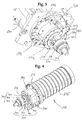
- Fig. 3 shows an exemplary perspective detail view of a tool holder 173 of a work spindle 172 according to an embodiment of the invention, for example according to Figs. 2A to 2E
- Fig. 4 shows an exemplary perspective view of a spindle device 170 according to an embodiment of the invention, for example, the spindle device 170 on the spindle carrier carriage 171 according to Figs. 2A to 2E can be installed.
- the spindle device 170 includes by way of example a spindle housing 175, in which, for example, the spindle drive or spindle motor can be arranged, and an example on the spindle housing 175 on the side of the tool holder 173 attached mounting frame 176, which is exemplified as an annular mounting frame on which the spindle device 170 can be attached or attached to the spindle carrier slide 171, for example.
- the coupling interface unit 330 of the tool coupling system 300 is preferably fixed in a positionally and rotationally fixed manner, e.g. through a fixed screw connection.
- the energy transfer unit 320 of the tool coupling system 300 is preferably detachable and preferably fixed in place and rotationally fixed, e.g. via a detachable locking connection.
- the power transmission unit 320 of the tool coupling system 300 according to FIG Figs. 3 and 4 includes, for example, a coupling element 321, which is attached to the coupling interface unit 330 preferably releasably and preferably fixed in place and rotationally fixed.
- a coil holder element 322 is arranged, which for example holds a transmitting coil unit 323, in which a transmitting coil or a transmitting coil segment 324 is arranged.
- the tool interface unit 310 includes, by way of example, a tool interface body 311, which is accommodated by way of example in the tool receptacle 173 of the work spindle 172 and is configured, for example, as a hollow shaft taper or hollow shaft taper section. Further, on the side opposite to the tool interface body 311, the tool interface unit 310 further comprises, by way of example, a tool receiving portion 313 for receiving a tool such as a tool. a milling or drilling tool. Between the tool receiving portion 313 and the tool interface body 311, the tool interface unit 310 includes, for example, a receiver coil unit 312 in which a receiver coil 314 may be disposed.
- Figs. 5A and 5B show exemplary perspective detailed representations of the spindle device 170 according to Fig. 4 with tool interface unit 310 inserted therein.
- the tool coupling system 300 with the coupling interface unit 330 and the power transmission unit 320 is arranged on or next to the work spindle 172 or the tool holder 173 such that the transmission coil segment 324 of the transmitting coil unit 323 is viewed in the axial direction with respect to the spindle axis over or at least partially over the receiver coil 324 of the receiver coil unit 312 the tool interface unit 310 is arranged.
- receiver coil 324 of the receiver coil unit 312 and the transmitter coil or transmitter coil segment 324 of the transmitter coil unit 323 overlap or partially overlap in the axial direction with respect to the spindle axis), if they are received on the tool holder 173 of the work spindle 172 is clamped.
- the receiver coil unit 312 and the transmitting coil unit 323 are arranged to each other in this state to each other that a thin air gap between the receiver coil unit 312 and the transmitting coil unit 323 is provided, such that when being driven by the work spindle 172 recorded in the tool holder 173 or clamped Tool interface unit 310 can rotate freely around the spindle axis, without coming into contact with the fixed power transmission unit 320 or to grind at this, while still using a magnetic energy transfer analogous to a transformer electrical energy or electrical signals without contact via the air gap between the receiver coil unit 312 and the transmitting coil unit 323 can be transmitted.
- the tool interface unit 310 has one or more electrical consumers which are or must be supplied with electrical energy during the machining of the workpiece WS or, in particular, during the spindle-driven rotational movement of the tool interface unit 310.
- the tool interface unit 310 preferably includes one or more controllable actuators and / or one or more readable sensors (eg, temperature sensors, vibration sensors, or electrical, optical, or inductive collision sensors) connected via the non-contact electro-magnetic connection between the receiver coil unit 312 of the tool interface unit 310 and the transmitting coil unit 323 of the power transmission unit 320 can be supplied with electrical energy and / or controlled by electrical control signals or by the non-contact electromagnetic connection between the receiver coil unit 312 of the tool interface unit 310 and the transmitting coil unit 323 the power transmission unit 320 electrical sensor or Regel- or other feedback signals from the tool interface unit 310 can be transmitted back.
- one or more controllable actuators and / or one or more readable sensors eg, temperature sensors, vibration sensors, or electrical, optical, or inductive collision sensors
- the tool interface unit 310 includes one or more vibration actuators for generating a vibration in the axial and / or radial direction with respect to the spindle axis or tool interface axis, particularly preferably in the ultrasonic frequency range, eg for ultrasonic processing the machining rotation of the tool is superimposed with a vibration in the ultrasonic range.
- vibration actuators or piezoelectric elements can be used for the controllable or controllable generation of the vibration or oscillation.
- DE 10 2012 219 254 A1 and DE 10 2013 210 199 A1 referenced tools, tooling devices and machining methods are examples of the vibration actuators.
- Figs. 6A and 6B show exemplary perspective detailed representations of the spindle device 170 according to Fig. 4 without inserted tool interface unit 310.
- the transmitting coil unit 323 of the energy transmission unit 320 with the transmitting coil segment 324 does not form a complete circular shape, but is designed as a partial circle segment which is arranged or placed only on one side of the tool holder 173 of the work spindle 172.
- the energy transfer unit 320 with the transmitting coil segment 324 can be provided in a space-saving and cost-effective manner, and, moreover, the space around the tool holder 173 can be kept largely free despite the energy transfer unit 320 with the transmitting coil segment 324.
- the work spindle 172 and the tool holder 173 are clearly visible, and moreover, the replacement of a tool interface is facilitated even when the power transmission unit 320 with the transmitting coil segment 324 is positioned on the work spindle 172.
- Figs. 7A to 7C show exemplary detailed perspective views of a tool coupling system 300 according to an embodiment of the invention. This includes, by way of example, the previously described units including the tool interface unit 310, the power transfer unit 320, and the docking interface unit 330.
- FIGS. 8A and 8B 11 show exemplary detailed perspective views of the tool interface unit 310 of the tool coupling system 300 according to FIG Figs. 7A to 7C and Figs. 9A and 9B show exemplary perspective detailed representations of the tool coupling system 300 according to FIG Figs. 7A to 7C without tool interface unit 310.
- the underside of the receiver coil unit 312 of the tool interface unit 310 can be seen, on which the section of the receiver coil 314 can be seen, which extends by way of example annularly and exemplarily completely around the tool interface axis or in the housing of the receiver coil unit 312.
- the receiver coil unit 312 can continuously hold the non-contact contact with the transmitting coil unit 323 of the energy transmission unit 320, which is formed only in a segment-shaped or partial circle segment, during the spindle-driven rotation of the tool interface unit 310.
- the tool interface unit 310 forms a gripper groove 311a around a circumference of the tool interface body 311, against which a gripper portion of a tool changer or a gripper of the tool changer 190 according to FIG Fig. 1 for tool change on the work spindle 172, the tool interface unit 310 may engage, eg, to replace it with another tool or other tool interface unit 310.
- the coupling interface unit 330 comprises by way of example a coupling element 331 which can be coupled to the coupling element 321 of the energy transmission unit 320 or to which the coupling element 321 of the energy transmission unit 320 can preferably be attached releasably and preferably fixed in place and rotation.
- the coupling interface unit 330 further comprises, for example, an interface body element 332 arranged on the side opposite the coupling element 331 for attachment to the spindle device 170 or the spindle carrier slide 171, wherein fastening elements 333 for the stationary and rotationally fixed attachment are provided on the interface body element 332 on the side facing away from the coupling element 321 (For example, by screw) on the spindle device 170 and on the work spindle 172, to which the work spindle 172 adjacent portion of the spindle mounting frame 176 or on a working spindle 172 adjacent portion of the spindle carrier carriage 171 can be fastened.
- fastening elements 333 for the stationary and rotationally fixed attachment are provided on the interface body element 332 on the side facing away from the coupling element 321 (For example, by screw) on the spindle device 170 and on the work spindle 172, to which the work spindle 172 adjacent portion of the spindle mounting frame 176 or on a working spindle 172 adjacent portion of the
- connection elements 334 allow, e.g. an external connection of electrical signal and / or power lines via the connected coupling elements to the transmitting coil 324 of the transmitting coil unit 323 for the electrical power supply of the tool interface unit or for input and / or output of control, regulating, and / or sensor signals.
- hydraulic and / or pneumatic connections may be provided, e.g.
- the coupling of the coupling elements 321 and 331 of the power transmission unit 320 and the coupling interface unit 330 is e.g. can be switched pneumatically and / or hydraulically between a locked or latched connection state and an unlocked or disengaged connection state.
- Such a switchable unlocking and locking of the coupling elements can also be electrically controlled in further embodiments.
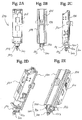
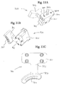
- Figs. 10A and 10B 11 each show exemplary detailed perspective views of the coupling interface unit 330 and the power transmission unit 320 of the tool coupling system according to FIG Figs. 7A to 7C , in decoupled or dissolved state.
- Fig. 10B 11 shows the power transmission unit 320 already described above with the coupling element 321 of the power transmission unit 320 (which can be coupled to the coupling element 331 of the coupling interface unit 330), the coil holder element 322, the transmitting coil unit 323 and the transmitting coil segment 324.
- Fig. 10A shows the coupling interface unit 330 already described above with the fasteners 333, the interface body member 332 and the coupling member 331 of the coupling interface unit 330 (which is coupled to or releasably attachable to the coupling member 321 of the power transmission unit 320).
- the coupling element 331 On the underside of the coupling element 331 of the coupling interface unit 330, the coupling element 331 has a coupling section 331a for coupling or releasable fastening to the coupling element 321 of the energy transmission unit 320.
- the coupling portion 331a includes, for example, a plurality of fixing portion openings 331b (eg, for receiving fasteners for coupling to the coupling member 321 of the power transmission unit 320) and, for example, contact receiving openings 331c (eg for electrical contact connections for electrical signal and / or power lines to the transmitting coil unit 323 of the energy transmission unit 323) arranged between the fastening section openings 331b.
- Figs. 11A and 11B show exemplary detailed perspective views of the power transmission unit 320 according to FIG Fig. 10B and Fig. 11C shows an exemplary bottom view of the power transmission unit 320 according to Fig. 10B ,
- the coupling element 322 is fastened to the coil holder element 322 by means of a screw connection with, for example, four screws (see FIG Figs. 11B and 11C ), and the transmitting coil unit 323 is fixed to the coil holder member 322 by means of a screw connection with, for example, a screw (see FIG Figs. 11A and 11B ).
- the coupling element 322 On the upper side of the coupling element 322 of the power transmission unit 320, the coupling element 322 has a coupling portion 321a for coupling or detachable attachment to the coupling element 331 of the coupling interface unit 330.
- the coupling portion 321a includes, by way of example, a plurality of fixing portion openings 321b (eg, for receiving fasteners for coupling to the coupling member 331 of the coupling interface unit 330), and contact receiving holes 321c (eg, for electrical contact connections for electrical connections) arranged between the fixing portion openings 321b Signal and / or power lines to the transmitter coil unit 323).
- the coupling sections 321a and 331a are each preferably designed as a plug-in connection system, the respective fastening section openings 321b and 331b preferably each having mechanical plug connection elements, and the contact receiving openings 321c and 331c preferably each having electrical contact plug connection elements
- the attachment portion openings 321b of the coupling member 321 of the power transmission unit 320 may include mechanically male connector elements, and the attachment portion openings 331b of the coupling member 331 of the coupling interface unit 330 may have corresponding mechanically female connector elements.
- the attachment portion openings 321b of the coupling member 321 may be the power transmission unit 320, e.g. mechanically female connector elements and the attachment portion openings 331b of the coupling element 331 of the coupling interface unit 330 may have corresponding mechanically male connector elements.
- the fixing portion openings 321b of the coupling member 321 of the power transmission unit 320 are e.g. mechanically female and mechanically male connector elements and the attachment portion openings 331b of the coupling element 331 of the coupling interface unit 330 corresponding mechanical male and female connector elements have.
- the contact receiving openings 321c may also have electrically male and / or female contact plug connection elements, and the contact receiving openings 331c may have corresponding electrically female and / or male contact plug connection elements.
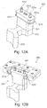
- Fig. 12A shows an exemplary perspective view of a power transmission unit 320 according to an embodiment of the invention
- Fig. 12B shows an exemplary perspective view of the power transmission unit 320 according to Fig. 12A in a coupling element receptacle 341 of a coupling element holder 340.
- the coupling portion 321a of the coupling member 321 of the power transmission unit 320 is equipped with mechanically male connector elements 321e in the attachment portion openings.
- These plug-in connection elements 321e (for example fixing bolts 321e) are designed, for example, as latching bolts for a detachable latching connection with the coupling element 331 of the coupling interface unit 330.
- the contact-receiving openings of the coupling element 321 of the power transmission unit 320 in FIG Figs. 12A and 12B provided by way of example electrically male contact plug-in elements.
- the coupling element 321 has laterally arranged holding sections 321f.
- the coupling member 321 may be held with the holding portions 321f on the coupling member receptacle 341 of the coupling member holder 340.
- such a coupling element holder 340 may be provided to the machine tool 100 to store or stock the power transfer unit 320 when not docked to the docking interface unit 330.
- the different power transmission units 320 all preferably have a like coupling element 331, e.g. can advantageously be docked or coupled to the same coupling interface unit 330. This advantageously makes it possible to optionally change the energy transfer unit 320 according to any desired exchanges of tool interface units 310.
- the power transfer unit 320 can advantageously be easily stored on the coupling element holder 340 if a normal tool is to be exchanged with the tool changer 190 on the work spindle 172 instead of a tool cutting unit 310, or even if any material applicator 230 of a material application processing system 200 to be used on the tool holder 173 of the work spindle 172.
- a controllable manipulator or handling robot can optionally be provided with a gripping device on a machine tool 100, which is set up to automatically remove or deposit an energy transfer unit 320 on a coupling element holder 340 and / or a docked to the coupling interface unit 330 or coupled and releasably mounted energy transfer unit 320, if necessary, automatically receive or an energy transfer unit 320 on the coupling interface unit 330, where appropriate, automatically releasably attached dock or dock.
- Figs. 13A to 13D show exemplary perspective detailed representations of the spindle device 170 according to Fig. 4 with inserted material application device 230 according to an embodiment of the invention.
- the material application device 230 comprises a processing head housing 231, on which a material application processing head 232 is held, which for example has a nozzle for applying material to a workpiece.
- the material application machining head 232 is formed as a laser head adapted to apply material to a surface of a workpiece by build-up welding, wherein a metallic powder is applied to the surface of the workpiece through the nozzle of the material application machining head 232 and by means of a laser beam the surface is welded.
- a processing head housing 231 on which a material application processing head 232 is held, which for example has a nozzle for applying material to a workpiece.
- the material application machining head 232 is formed as a laser head adapted to apply material to a surface of a workpiece by build-up welding, wherein a metallic powder is applied to the surface of the workpiece through the nozzle of the material application machining head 232 and by means of a laser beam the surface is welded.
- the supply line 233 is attached to the material application device 230 and connected to the material application processing head 232.
- the material application device 230 is received on the work spindle 172 of the spindle device 170 by way of example.
- the coupling interface unit 330 attached to the spindle device 170 according to the exemplary embodiments described above can be seen, on the coupling element of which a further coupling element of a coupling element adapter 350 for the material application device 230 is provided.
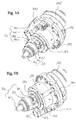
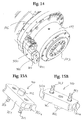
- Fig. 14 shows an exemplary perspective detailed representation of the spindle device 170 according to Fig. 4 without material applicator device 230 used.
- the coupling element adapter 350 for the material application device 230 can be recognized in the coupling element 333 of the above-described coupling interface unit 330 coupled or docked state of the releasable attachment of the coupling elements, wherein the coupling element adapter 350 a Coupling element 351 analogous to the coupling element 321 of the energy transfer unit 320 described above.
- Figs. 15A and 15B show exemplary detailed perspective views of the coupling element adapter 350 of the tool coupling system 300 according to an embodiment of the invention.
- the coupling element 351 of the coupling element adapter 350 has, analogously to the coupling element 321 of the energy transfer unit 320 described above, lateral holding sections 351 a, on which the coupling element adapter 350 is analogous to the energy transfer unit 320 according to FIG Fig. 12B can be received and held on the coupling element receptacle 341 of the coupling element holder 340. Furthermore, the coupling element 351 of the coupling element adapter 350 has an example analogous to the energy transmission unit 320 according to FIG Fig. 12A Fixing bolts 353 as plug-in connection elements. In this case, male and / or female plug connection elements can be provided in further embodiments according to the configuration of the coupling cut unit 330.
- the coupling element 351 of the coupling element adapter 350 has, for example, another fastening element 352 (designed as a mechanically male plug connection element, for example) for releasable connection to a corresponding fastening element 360 of the tool coupling system 300 (see FIG Fig. 16 ).
- the fasteners 352 and 360 are formed as corresponding mating connector elements.
- Fig. 16 shows an exemplary perspective view of the material application device 230 according to Figs. 13A to 13D , This includes, as exemplified above, the material application processing head 232 and the connected supply line 233 held on the processing head housing 231. Further, on the processing head housing 231, on the side opposite to the material application processing head 232, a tool interface body 234 is formed, which is exemplified as a hollow shaft taper Interface section is formed.
- the tool holder 173 of the work spindle 172 is configured analogously to the receiving of the tool interface body 311 of the tool interface unit 310, the tool interface body 234 of the material application device 230 absorb or clamp. Adjacent to and adjacent to the tool interface body 234, the fastener 360 of the tool coupling system 300 is attached to the machining head housing 231 on the opposite side of the material application machining head 232, and possibly fastened by screw connection.
- the fasteners 360 and 252 are connected together, for example by means of a transversely to the spindle axis fixed positive connection.
- the second connection of the fastening elements 360 and 252 advantageously stabilizes the orientation of the material application device 230 even with rapid movement of the spindle carrier 171 in the horizontal direction (ie, for example in the directions of the X and Y axes of the Achsschlitten assembly of the machine tool 100) and thus advantageously prevents a rotation of the material application device 230 with rapid movement of the spindle carrier 171 in the horizontal direction and any undesirable ringing of the material application device 230 about the spindle axis.
- a versatile and space-saving and cost-saving tool interface system or coupling interface system for machine tools is provided, in particular space and cost-saving with advantageous synergistic effects in terms of advantageous energy and signal transmission or supply and on advantageously efficient, time-saving and versatile tool change options and precise tooling and processing head alignment particularly advantageous when used on hybrid machine tools can be used, in which, if necessary, in addition to a conventional machining machining other processing options are combinable, such as with electrical consumers having tool interface units, for example, in the ultrasonic processing application, and / or in connection with material application processing heads for applying material the conventionally material-removing machine tool.
Landscapes
- Engineering & Computer Science (AREA)
- Mechanical Engineering (AREA)
- Physics & Mathematics (AREA)
- Optics & Photonics (AREA)
- Plasma & Fusion (AREA)
- Computer Networks & Wireless Communication (AREA)
- Power Engineering (AREA)
- Automatic Tool Replacement In Machine Tools (AREA)
- Jigs For Machine Tools (AREA)
- Turning (AREA)
Priority Applications (1)
| Application Number | Priority Date | Filing Date | Title |
|---|---|---|---|
| PL16187808T PL3144098T3 (pl) | 2015-09-18 | 2016-09-08 | Układ sprzęgający do stosowania na przyrządzie wrzecionowym obrabiarki |
Applications Claiming Priority (1)
| Application Number | Priority Date | Filing Date | Title |
|---|---|---|---|
| DE102015218030.1A DE102015218030A1 (de) | 2015-09-18 | 2015-09-18 | Kopplungssystem zur Verwendung an einer Spindelvorrichtung einer Werkzeugmaschine |
Publications (3)
| Publication Number | Publication Date |
|---|---|
| EP3144098A2 true EP3144098A2 (fr) | 2017-03-22 |
| EP3144098A3 EP3144098A3 (fr) | 2017-07-12 |
| EP3144098B1 EP3144098B1 (fr) | 2021-08-25 |
Family
ID=56889001
Family Applications (1)
| Application Number | Title | Priority Date | Filing Date |
|---|---|---|---|
| EP16187808.7A Active EP3144098B1 (fr) | 2015-09-18 | 2016-09-08 | Système de couplage pour utiliser sur une broche d'une machine-outil |
Country Status (11)
| Country | Link |
|---|---|
| US (1) | US10596666B2 (fr) |
| EP (1) | EP3144098B1 (fr) |
| JP (1) | JP6393300B2 (fr) |
| CN (1) | CN106825653B (fr) |
| CA (1) | CA2941939C (fr) |
| DE (1) | DE102015218030A1 (fr) |
| DK (1) | DK3144098T3 (fr) |
| ES (1) | ES2886027T3 (fr) |
| PL (1) | PL3144098T3 (fr) |
| RU (1) | RU2727624C2 (fr) |
| SG (1) | SG10201607591RA (fr) |
Cited By (2)
| Publication number | Priority date | Publication date | Assignee | Title |
|---|---|---|---|---|
| US20230166372A1 (en) * | 2020-03-11 | 2023-06-01 | Sales S.R.L. | Device for the automatic connection of a high speed spindle to a numerically controlled machine |
| CN116690303A (zh) * | 2023-06-30 | 2023-09-05 | 南通国盛智能科技集团股份有限公司 | 一种机床防撞刀控制方法、机床以及计算机可读存储介质 |
Families Citing this family (25)
| Publication number | Priority date | Publication date | Assignee | Title |
|---|---|---|---|---|
| US20170129180A1 (en) | 2014-06-09 | 2017-05-11 | Hybrid Manufacturing Technologies Limited | Material processing methods and related apparatus |
| CN107124042A (zh) * | 2017-06-30 | 2017-09-01 | 河南理工大学 | 适用于超声加工中心自动换刀的环压式无线电能传输系统 |
| DE102017213364A1 (de) * | 2017-08-02 | 2019-02-07 | Trumpf Werkzeugmaschinen Gmbh + Co. Kg | Funktionseinheit für einen Bearbeitungskopf, Bearbeitungskopf und Funktionselement |
| DE102017215840B4 (de) | 2017-09-07 | 2025-02-20 | Sauer Gmbh | Laserbearbeitungskopf |
| CN107717593A (zh) * | 2017-11-16 | 2018-02-23 | 贵州航帆精密机械制造有限公司 | 一种专用于加工有机玻璃的设备 |
| CN108788855A (zh) * | 2018-05-21 | 2018-11-13 | 广州汇专工具有限公司 | 电磁发射支架及电磁发射装置 |
| CN108381255A (zh) * | 2018-05-21 | 2018-08-10 | 广州汇专工具有限公司 | 电磁发射支架及电磁发射装置 |
| CN108526904B (zh) * | 2018-06-11 | 2023-09-29 | 乐清市三环精密机械有限公司 | 一种多工位滑块加工一体机构 |
| CN108942645B (zh) * | 2018-06-28 | 2024-02-20 | 厦门达科塔机械有限公司 | 精准控制感知量的磨头装置 |
| CN110091160B (zh) * | 2019-05-28 | 2021-02-23 | 江南大学 | 一种钢桶大螺纹盖装配流水线 |
| DE102019212302A1 (de) * | 2019-08-16 | 2021-02-18 | Robert Bosch Gmbh | Bearbeitungswerkzeug, insbesondere Oszillationsbearbeitungswerkzeug |
| TWI717067B (zh) * | 2019-10-23 | 2021-01-21 | 財團法人工業技術研究院 | 主軸電能及訊號傳輸裝置 |
| CN110802423B (zh) * | 2019-11-08 | 2021-07-20 | 深圳市特力威科技有限公司 | 超声波刀把总成 |
| JP7148157B2 (ja) * | 2020-06-04 | 2022-10-05 | 株式会社Rs-JAPAN | 加工装置および超音波ツールチャック |
| CN112317780B (zh) * | 2020-11-09 | 2022-07-08 | 汇专机床有限公司 | 超声波主轴、超声波刀柄及超声波机床 |
| CN112317781B (zh) * | 2020-11-09 | 2022-03-04 | 汇专机床有限公司 | 超声波主轴、超声波刀柄及超声波加工设备 |
| CN112720164A (zh) * | 2020-12-07 | 2021-04-30 | 昆山肯达欧曼燃油喷射系统有限公司 | 立式车床用电动打磨装置 |
| JP7126013B1 (ja) * | 2021-04-26 | 2022-08-25 | Dmg森精機株式会社 | 工作機械用装置および工作機械 |
| CN113829205A (zh) * | 2021-09-06 | 2021-12-24 | 戴杰磨床有限公司 | 一种高精加工的五轴磨床 |
| CN114029521B (zh) * | 2021-11-24 | 2024-06-07 | 太炫科技(南京)有限公司 | 一种医疗用弧形板精密定位打孔设备 |
| CN114453978A (zh) * | 2022-01-18 | 2022-05-10 | 东莞市银泽实业有限公司 | 一种钻头抖动分析及外径测量装置 |
| WO2024101459A1 (fr) * | 2022-11-07 | 2024-05-16 | エヌティーエンジニアリング株式会社 | Dispositif de fixation/séparation automatique d'unité de bobine de transmission dans un dispositif d'alimentation électrique sans contact |
| CN116586985B (zh) * | 2023-07-12 | 2024-01-30 | 杭州铭达五金有限公司 | 一种轴承座加工用切削装置 |
| KR102765605B1 (ko) * | 2023-11-20 | 2025-02-11 | 주식회사 팀스핀들 | 연삭장비용 스핀들의 진동센서 설치 구조 |
| DE102023135855A1 (de) | 2023-12-19 | 2025-06-26 | Dmg Mori Pfronten Gmbh | Auswechselbarer Erweiterungsadapter und Verfahren für eine Arbeitsspindel einer Werkzeugmaschine |
Citations (5)
| Publication number | Priority date | Publication date | Assignee | Title |
|---|---|---|---|---|
| DE102009008227A1 (de) | 2009-02-10 | 2010-08-26 | Sauer Ultrasonic Gmbh | Schnittstelle für einen Werkzeugaktor bzw. für ein Werkzeug, insbesondere zum Verbinden mit einer Werkzeugmaschine |
| WO2014013247A2 (fr) | 2012-07-16 | 2014-01-23 | Exscintilla Limited | Machine-outil |
| DE102012219254A1 (de) | 2012-10-22 | 2014-04-24 | Sauer Ultrasonic Gmbh | Verfahren zur Werkstückbearbeitung, Versorgungsschaltung, Versorgungssystem, Werkzeugaktor, Werkzeugaufbau |
| DE102013210199A1 (de) | 2013-05-31 | 2014-12-04 | Sauer Ultrasonic Gmbh | Werkzeug |
| DE102013224649A1 (de) | 2013-11-29 | 2015-06-03 | Sauer Gmbh Lasertec | Werkzeugmaschine, Messvorrichtung, Verfahren zum Erstellen von Arbeitsdaten, Auftragsschweißverfahren, Werkstücktemperiervorrichtung |
Family Cites Families (23)
| Publication number | Priority date | Publication date | Assignee | Title |
|---|---|---|---|---|
| JPS59501875A (ja) * | 1982-10-15 | 1984-11-08 | レニシヨウ パブリツク リミテツド カンパニ− | 位置検知装置 |
| SU1442380A1 (ru) * | 1987-04-02 | 1988-12-07 | В.Н.Пигулевский, Ю.В.Скорынин и М.А.Леванцевич | Шпиндель металлорежущего станка |
| JP2818937B2 (ja) * | 1988-01-06 | 1998-10-30 | エヌティーエンジニアリング株式会社 | 作業機械 |
| JPH05208349A (ja) * | 1992-01-29 | 1993-08-20 | Mitsubishi Heavy Ind Ltd | 主軸ユニット |
| DE4330820A1 (de) * | 1993-09-13 | 1995-03-16 | Komet Stahlhalter Werkzeug | Werkzeugkopf mit externer Stromversorgung |
| JPH0819903A (ja) * | 1994-07-05 | 1996-01-23 | Hitachi Seiki Co Ltd | ワーク把持及び主軸駆動装置 |
| TW499978U (en) * | 2001-10-19 | 2002-08-21 | Jin-Shiang Chen | Rope-pushing body-building apparatus |
| JP2004001107A (ja) | 2002-05-30 | 2004-01-08 | Orio Seiki Kk | 超音波振動工具を備えた工作機械 |
| RU2250814C1 (ru) * | 2003-10-02 | 2005-04-27 | Государственное образовательное учреждение высшего профессионального образования "Алтайский государственный технический университет им. И.И. Ползунова" | Ультразвуковая колебательная система для размерной обработки |
| DE102005011197B4 (de) * | 2005-03-09 | 2013-03-07 | Komet Group Gmbh | Drehübertrager und damit ausgerüstetes Maschinengestell |
| US7360976B2 (en) * | 2005-05-12 | 2008-04-22 | Bryan Steve M | Air valve coupling method and apparatus |
| DE102007024503C5 (de) * | 2007-05-25 | 2011-07-28 | MAPAL Fabrik für Präzisionswerkzeuge Dr. Kress KG, 73431 | Übertragungseinrichtung |
| DE102010003338A1 (de) * | 2010-03-26 | 2011-09-29 | Komet Group Gmbh | Werkzeugmaschine mit Drehübertrager für Daten |
| DE102011005339A1 (de) * | 2011-03-10 | 2012-09-13 | Komet Group Gmbh | Drehübertrager für Werkzeugmaschinen |
| DE102012222360A1 (de) * | 2012-12-05 | 2014-06-18 | Sauer Ultrasonic Gmbh | Werkzeug, Bearbeitungsverfahren |
| EP2796233A1 (fr) * | 2013-04-24 | 2014-10-29 | Karl Hiestand | Dispositif de couplage |
| RU2548344C2 (ru) * | 2013-06-27 | 2015-04-20 | Федеральное государственное бюджетное образовательное учреждение высшего профессионального образования "Саратовский государственный технический университет имени Гагарина Ю.А." (СГТУ имени Гагарина Ю.А.) | Устройство для ультразвуковой обработки |
| AT513629B1 (de) * | 2013-08-12 | 2014-06-15 | Wfl Millturn Tech Gmbh & Co Kg | Werkzeugmaschine mit einer Primärspule zur kontaktlosen Energie- und/oder Signalübertragung |
| EP2868410B1 (fr) * | 2013-10-30 | 2017-12-13 | MTH GbR Markus und Thomas Hiestand | Dispositif de serrage pour machines-outils |
| US20170129180A1 (en) * | 2014-06-09 | 2017-05-11 | Hybrid Manufacturing Technologies Limited | Material processing methods and related apparatus |
| TWM499978U (zh) | 2014-12-31 | 2015-05-01 | Tongtai Machine & Tool Co Ltd | 加工機具之供電刀把 |
| CN204658046U (zh) * | 2015-05-28 | 2015-09-23 | 天津大学 | 一种基于机床附件化的局部感应的旋转超声波头 |
| DE202019103076U1 (de) * | 2019-05-31 | 2019-06-11 | Ying Hsin Liang | Durch Ultraschall in Schwingung versetzbarer Werkzeuggriff eines Zerspanungswerkzeugs |
-
2015
- 2015-09-18 DE DE102015218030.1A patent/DE102015218030A1/de not_active Ceased
-
2016
- 2016-09-08 DK DK16187808.7T patent/DK3144098T3/da active
- 2016-09-08 EP EP16187808.7A patent/EP3144098B1/fr active Active
- 2016-09-08 PL PL16187808T patent/PL3144098T3/pl unknown
- 2016-09-08 ES ES16187808T patent/ES2886027T3/es active Active
- 2016-09-13 SG SG10201607591RA patent/SG10201607591RA/en unknown
- 2016-09-14 CN CN201610825224.5A patent/CN106825653B/zh active Active
- 2016-09-14 CA CA2941939A patent/CA2941939C/fr active Active
- 2016-09-16 JP JP2016181495A patent/JP6393300B2/ja active Active
- 2016-09-16 RU RU2016137128A patent/RU2727624C2/ru active
- 2016-09-16 US US15/267,933 patent/US10596666B2/en active Active
Patent Citations (5)
| Publication number | Priority date | Publication date | Assignee | Title |
|---|---|---|---|---|
| DE102009008227A1 (de) | 2009-02-10 | 2010-08-26 | Sauer Ultrasonic Gmbh | Schnittstelle für einen Werkzeugaktor bzw. für ein Werkzeug, insbesondere zum Verbinden mit einer Werkzeugmaschine |
| WO2014013247A2 (fr) | 2012-07-16 | 2014-01-23 | Exscintilla Limited | Machine-outil |
| DE102012219254A1 (de) | 2012-10-22 | 2014-04-24 | Sauer Ultrasonic Gmbh | Verfahren zur Werkstückbearbeitung, Versorgungsschaltung, Versorgungssystem, Werkzeugaktor, Werkzeugaufbau |
| DE102013210199A1 (de) | 2013-05-31 | 2014-12-04 | Sauer Ultrasonic Gmbh | Werkzeug |
| DE102013224649A1 (de) | 2013-11-29 | 2015-06-03 | Sauer Gmbh Lasertec | Werkzeugmaschine, Messvorrichtung, Verfahren zum Erstellen von Arbeitsdaten, Auftragsschweißverfahren, Werkstücktemperiervorrichtung |
Cited By (3)
| Publication number | Priority date | Publication date | Assignee | Title |
|---|---|---|---|---|
| US20230166372A1 (en) * | 2020-03-11 | 2023-06-01 | Sales S.R.L. | Device for the automatic connection of a high speed spindle to a numerically controlled machine |
| US12311488B2 (en) * | 2020-03-11 | 2025-05-27 | Sales S.R.L. | Device for the automatic connection of a high speed spindle to a numerically controlled machine |
| CN116690303A (zh) * | 2023-06-30 | 2023-09-05 | 南通国盛智能科技集团股份有限公司 | 一种机床防撞刀控制方法、机床以及计算机可读存储介质 |
Also Published As
| Publication number | Publication date |
|---|---|
| EP3144098A3 (fr) | 2017-07-12 |
| CN106825653A (zh) | 2017-06-13 |
| RU2016137128A (ru) | 2018-03-21 |
| EP3144098B1 (fr) | 2021-08-25 |
| CA2941939A1 (fr) | 2017-03-18 |
| DE102015218030A1 (de) | 2017-03-23 |
| CN106825653B (zh) | 2020-02-14 |
| US10596666B2 (en) | 2020-03-24 |
| RU2727624C2 (ru) | 2020-07-22 |
| RU2016137128A3 (fr) | 2020-02-10 |
| DK3144098T3 (da) | 2021-10-11 |
| PL3144098T3 (pl) | 2022-01-03 |
| ES2886027T3 (es) | 2021-12-16 |
| US20170080537A1 (en) | 2017-03-23 |
| JP6393300B2 (ja) | 2018-09-19 |
| CA2941939C (fr) | 2023-09-05 |
| JP2017056554A (ja) | 2017-03-23 |
| SG10201607591RA (en) | 2017-04-27 |
Similar Documents
| Publication | Publication Date | Title |
|---|---|---|
| EP3144098B1 (fr) | Système de couplage pour utiliser sur une broche d'une machine-outil | |
| EP3195977A1 (fr) | Machine-outil, en particulier fraiseuse multibroche | |
| DE102015000503A1 (de) | Bearbeitungsvorrichtung zur maschinengeschützten Herstellung und Bearbeitung von dentalen Werkstücken | |
| EP3525967B1 (fr) | Procédé d'usinage de pièces dans une machine-outil et machine-outil appropriée | |
| EP3412403B1 (fr) | Machine-outil destinée à l'usinage par enlèvement de copeaux d'une pièce à usiner | |
| DE19614641A1 (de) | Vorrichtung zur Bearbeitung und Montage von Werkstücken | |
| EP3195976A1 (fr) | Machine-outil, en particulier fraiseuse multibroche | |
| EP3475022B1 (fr) | Unité d'usinage pour usiner une pièce au moyen d'un faisceau d'usinage thermique, comprenant un dispositif d'accouplement | |
| DE102011082839A1 (de) | Handhabungsvorrichtung für eine Werkzeugmaschine | |
| DE102019122449A1 (de) | Energie/Signal-Übertragungsstruktur und Werkzeugmaschine | |
| DE102012107627A1 (de) | Modulare Werkzeugmaschine | |
| DE102009011676A1 (de) | Bearbeitungsmaschine | |
| DE3634018C2 (fr) | ||
| WO2025131551A1 (fr) | Adaptateur d'extension échangeable et procédé pour broche de travail de machine-outil | |
| EP2054198B1 (fr) | Système interchangeable d'appareils de soudage pour dispositif de manipulation | |
| DE102018104199A1 (de) | Werkzeugmaschine mit Arbeitsraum, Rüstplatz und Roboterarm und Verfahren zu deren Betrieb | |
| EP3616836B1 (fr) | Dispositif d'usinage destiné à l'usinage par enlèvement de copeaux d'une pièce à usiner | |
| EP1169158A1 (fr) | Procede et dispositif destines a l'usinage de pieces | |
| DE102015218032A1 (de) | Werkzeugmaschine | |
| DE102007043421A1 (de) | Werkzeugmaschine | |
| WO2023247056A1 (fr) | Procédé et appareil de positionnement d'une pièce à usiner entre deux étaux | |
| DE3418893A1 (de) | Verfahren und vorrichtung zum be- und entladen von werkstuecken an einer werkzeugmaschine | |
| DE20317590U1 (de) | Bearbeitungszentrum mit wenigstens einem an einer Transportvorrichtung gelagerten Werkstückträger mit wenigstens einer Schwenkachse | |
| DE102022113434A1 (de) | Werkzeuggegenhalter und Werkzeugmaschine | |
| DE102010023610A1 (de) | Roboter mit Präzisionsführung |
Legal Events
| Date | Code | Title | Description |
|---|---|---|---|
| PUAI | Public reference made under article 153(3) epc to a published international application that has entered the european phase |
Free format text: ORIGINAL CODE: 0009012 |
|
| STAA | Information on the status of an ep patent application or granted ep patent |
Free format text: STATUS: THE APPLICATION HAS BEEN PUBLISHED |
|
| AK | Designated contracting states |
Kind code of ref document: A2 Designated state(s): AL AT BE BG CH CY CZ DE DK EE ES FI FR GB GR HR HU IE IS IT LI LT LU LV MC MK MT NL NO PL PT RO RS SE SI SK SM TR |
|
| AX | Request for extension of the european patent |
Extension state: BA ME |
|
| PUAL | Search report despatched |
Free format text: ORIGINAL CODE: 0009013 |
|
| AK | Designated contracting states |
Kind code of ref document: A3 Designated state(s): AL AT BE BG CH CY CZ DE DK EE ES FI FR GB GR HR HU IE IS IT LI LT LU LV MC MK MT NL NO PL PT RO RS SE SI SK SM TR |
|
| AX | Request for extension of the european patent |
Extension state: BA ME |
|
| RIC1 | Information provided on ipc code assigned before grant |
Ipc: B23Q 3/155 20060101ALI20170608BHEP Ipc: B23Q 5/04 20060101ALI20170608BHEP Ipc: B23K 26/34 20140101ALI20170608BHEP Ipc: B23Q 1/00 20060101AFI20170608BHEP Ipc: B23K 26/00 20140101ALI20170608BHEP Ipc: H02J 50/10 20160101ALI20170608BHEP Ipc: B23K 26/14 20140101ALI20170608BHEP |
|
| STAA | Information on the status of an ep patent application or granted ep patent |
Free format text: STATUS: REQUEST FOR EXAMINATION WAS MADE |
|
| 17P | Request for examination filed |
Effective date: 20180112 |
|
| RBV | Designated contracting states (corrected) |
Designated state(s): AL AT BE BG CH CY CZ DE DK EE ES FI FR GB GR HR HU IE IS IT LI LT LU LV MC MK MT NL NO PL PT RO RS SE SI SK SM TR |
|
| STAA | Information on the status of an ep patent application or granted ep patent |
Free format text: STATUS: EXAMINATION IS IN PROGRESS |
|
| 17Q | First examination report despatched |
Effective date: 20200110 |
|
| GRAP | Despatch of communication of intention to grant a patent |
Free format text: ORIGINAL CODE: EPIDOSNIGR1 |
|
| STAA | Information on the status of an ep patent application or granted ep patent |
Free format text: STATUS: GRANT OF PATENT IS INTENDED |
|
| INTG | Intention to grant announced |
Effective date: 20201125 |
|
| GRAJ | Information related to disapproval of communication of intention to grant by the applicant or resumption of examination proceedings by the epo deleted |
Free format text: ORIGINAL CODE: EPIDOSDIGR1 |
|
| STAA | Information on the status of an ep patent application or granted ep patent |
Free format text: STATUS: EXAMINATION IS IN PROGRESS |
|
| GRAP | Despatch of communication of intention to grant a patent |
Free format text: ORIGINAL CODE: EPIDOSNIGR1 |
|
| STAA | Information on the status of an ep patent application or granted ep patent |
Free format text: STATUS: GRANT OF PATENT IS INTENDED |
|
| INTC | Intention to grant announced (deleted) | ||
| RAP3 | Party data changed (applicant data changed or rights of an application transferred) |
Owner name: DMG MORI ULTRASONIC LASERTEC GMBH |
|
| INTG | Intention to grant announced |
Effective date: 20210420 |
|
| GRAS | Grant fee paid |
Free format text: ORIGINAL CODE: EPIDOSNIGR3 |
|
| GRAA | (expected) grant |
Free format text: ORIGINAL CODE: 0009210 |
|
| STAA | Information on the status of an ep patent application or granted ep patent |
Free format text: STATUS: THE PATENT HAS BEEN GRANTED |
|
| AK | Designated contracting states |
Kind code of ref document: B1 Designated state(s): AL AT BE BG CH CY CZ DE DK EE ES FI FR GB GR HR HU IE IS IT LI LT LU LV MC MK MT NL NO PL PT RO RS SE SI SK SM TR |
|
| REG | Reference to a national code |
Ref country code: CH Ref legal event code: EP |
|
| REG | Reference to a national code |
Ref country code: DE Ref legal event code: R096 Ref document number: 502016013682 Country of ref document: DE |
|
| REG | Reference to a national code |
Ref country code: IE Ref legal event code: FG4D Free format text: LANGUAGE OF EP DOCUMENT: GERMAN Ref country code: AT Ref legal event code: REF Ref document number: 1423294 Country of ref document: AT Kind code of ref document: T Effective date: 20210915 |
|
| REG | Reference to a national code |
Ref country code: DK Ref legal event code: T3 Effective date: 20211004 |
|
| REG | Reference to a national code |
Ref country code: FI Ref legal event code: FGE Ref country code: SE Ref legal event code: TRGR |
|
| REG | Reference to a national code |
Ref country code: NL Ref legal event code: FP |
|
| REG | Reference to a national code |
Ref country code: LT Ref legal event code: MG9D |
|
| REG | Reference to a national code |
Ref country code: ES Ref legal event code: FG2A Ref document number: 2886027 Country of ref document: ES Kind code of ref document: T3 Effective date: 20211216 |
|
| PG25 | Lapsed in a contracting state [announced via postgrant information from national office to epo] |
Ref country code: NO Free format text: LAPSE BECAUSE OF FAILURE TO SUBMIT A TRANSLATION OF THE DESCRIPTION OR TO PAY THE FEE WITHIN THE PRESCRIBED TIME-LIMIT Effective date: 20211125 Ref country code: PT Free format text: LAPSE BECAUSE OF FAILURE TO SUBMIT A TRANSLATION OF THE DESCRIPTION OR TO PAY THE FEE WITHIN THE PRESCRIBED TIME-LIMIT Effective date: 20211227 Ref country code: LT Free format text: LAPSE BECAUSE OF FAILURE TO SUBMIT A TRANSLATION OF THE DESCRIPTION OR TO PAY THE FEE WITHIN THE PRESCRIBED TIME-LIMIT Effective date: 20210825 Ref country code: BG Free format text: LAPSE BECAUSE OF FAILURE TO SUBMIT A TRANSLATION OF THE DESCRIPTION OR TO PAY THE FEE WITHIN THE PRESCRIBED TIME-LIMIT Effective date: 20211125 Ref country code: RS Free format text: LAPSE BECAUSE OF FAILURE TO SUBMIT A TRANSLATION OF THE DESCRIPTION OR TO PAY THE FEE WITHIN THE PRESCRIBED TIME-LIMIT Effective date: 20210825 Ref country code: HR Free format text: LAPSE BECAUSE OF FAILURE TO SUBMIT A TRANSLATION OF THE DESCRIPTION OR TO PAY THE FEE WITHIN THE PRESCRIBED TIME-LIMIT Effective date: 20210825 |
|
| PG25 | Lapsed in a contracting state [announced via postgrant information from national office to epo] |
Ref country code: LV Free format text: LAPSE BECAUSE OF FAILURE TO SUBMIT A TRANSLATION OF THE DESCRIPTION OR TO PAY THE FEE WITHIN THE PRESCRIBED TIME-LIMIT Effective date: 20210825 Ref country code: GR Free format text: LAPSE BECAUSE OF FAILURE TO SUBMIT A TRANSLATION OF THE DESCRIPTION OR TO PAY THE FEE WITHIN THE PRESCRIBED TIME-LIMIT Effective date: 20211126 |
|
| REG | Reference to a national code |
Ref country code: DE Ref legal event code: R097 Ref document number: 502016013682 Country of ref document: DE |
|
| PG25 | Lapsed in a contracting state [announced via postgrant information from national office to epo] |
Ref country code: SM Free format text: LAPSE BECAUSE OF FAILURE TO SUBMIT A TRANSLATION OF THE DESCRIPTION OR TO PAY THE FEE WITHIN THE PRESCRIBED TIME-LIMIT Effective date: 20210825 Ref country code: SK Free format text: LAPSE BECAUSE OF FAILURE TO SUBMIT A TRANSLATION OF THE DESCRIPTION OR TO PAY THE FEE WITHIN THE PRESCRIBED TIME-LIMIT Effective date: 20210825 Ref country code: RO Free format text: LAPSE BECAUSE OF FAILURE TO SUBMIT A TRANSLATION OF THE DESCRIPTION OR TO PAY THE FEE WITHIN THE PRESCRIBED TIME-LIMIT Effective date: 20210825 Ref country code: MC Free format text: LAPSE BECAUSE OF FAILURE TO SUBMIT A TRANSLATION OF THE DESCRIPTION OR TO PAY THE FEE WITHIN THE PRESCRIBED TIME-LIMIT Effective date: 20210825 Ref country code: EE Free format text: LAPSE BECAUSE OF FAILURE TO SUBMIT A TRANSLATION OF THE DESCRIPTION OR TO PAY THE FEE WITHIN THE PRESCRIBED TIME-LIMIT Effective date: 20210825 Ref country code: CZ Free format text: LAPSE BECAUSE OF FAILURE TO SUBMIT A TRANSLATION OF THE DESCRIPTION OR TO PAY THE FEE WITHIN THE PRESCRIBED TIME-LIMIT Effective date: 20210825 Ref country code: AL Free format text: LAPSE BECAUSE OF FAILURE TO SUBMIT A TRANSLATION OF THE DESCRIPTION OR TO PAY THE FEE WITHIN THE PRESCRIBED TIME-LIMIT Effective date: 20210825 |
|
| PLBE | No opposition filed within time limit |
Free format text: ORIGINAL CODE: 0009261 |
|
| STAA | Information on the status of an ep patent application or granted ep patent |
Free format text: STATUS: NO OPPOSITION FILED WITHIN TIME LIMIT |
|
| PG25 | Lapsed in a contracting state [announced via postgrant information from national office to epo] |
Ref country code: IE Free format text: LAPSE BECAUSE OF NON-PAYMENT OF DUE FEES Effective date: 20210908 |
|
| 26N | No opposition filed |
Effective date: 20220527 |
|
| PG25 | Lapsed in a contracting state [announced via postgrant information from national office to epo] |
Ref country code: SI Free format text: LAPSE BECAUSE OF FAILURE TO SUBMIT A TRANSLATION OF THE DESCRIPTION OR TO PAY THE FEE WITHIN THE PRESCRIBED TIME-LIMIT Effective date: 20210825 |
|
| PG25 | Lapsed in a contracting state [announced via postgrant information from national office to epo] |
Ref country code: HU Free format text: LAPSE BECAUSE OF FAILURE TO SUBMIT A TRANSLATION OF THE DESCRIPTION OR TO PAY THE FEE WITHIN THE PRESCRIBED TIME-LIMIT; INVALID AB INITIO Effective date: 20160908 |
|
| PG25 | Lapsed in a contracting state [announced via postgrant information from national office to epo] |
Ref country code: CY Free format text: LAPSE BECAUSE OF FAILURE TO SUBMIT A TRANSLATION OF THE DESCRIPTION OR TO PAY THE FEE WITHIN THE PRESCRIBED TIME-LIMIT Effective date: 20210825 |
|
| PG25 | Lapsed in a contracting state [announced via postgrant information from national office to epo] |
Ref country code: MK Free format text: LAPSE BECAUSE OF FAILURE TO SUBMIT A TRANSLATION OF THE DESCRIPTION OR TO PAY THE FEE WITHIN THE PRESCRIBED TIME-LIMIT Effective date: 20210825 |
|
| PG25 | Lapsed in a contracting state [announced via postgrant information from national office to epo] |
Ref country code: MT Free format text: LAPSE BECAUSE OF FAILURE TO SUBMIT A TRANSLATION OF THE DESCRIPTION OR TO PAY THE FEE WITHIN THE PRESCRIBED TIME-LIMIT Effective date: 20210825 |
|
| REG | Reference to a national code |
Ref country code: CH Ref legal event code: U11 Free format text: ST27 STATUS EVENT CODE: U-0-0-U10-U11 (AS PROVIDED BY THE NATIONAL OFFICE) Effective date: 20251001 |
|
| PGFP | Annual fee paid to national office [announced via postgrant information from national office to epo] |
Ref country code: FI Payment date: 20250922 Year of fee payment: 10 |
|
| PGFP | Annual fee paid to national office [announced via postgrant information from national office to epo] |
Ref country code: DE Payment date: 20250930 Year of fee payment: 10 Ref country code: DK Payment date: 20250922 Year of fee payment: 10 |
|
| PGFP | Annual fee paid to national office [announced via postgrant information from national office to epo] |
Ref country code: LU Payment date: 20250922 Year of fee payment: 10 Ref country code: PL Payment date: 20250827 Year of fee payment: 10 Ref country code: NL Payment date: 20250922 Year of fee payment: 10 Ref country code: TR Payment date: 20250903 Year of fee payment: 10 |
|
| PGFP | Annual fee paid to national office [announced via postgrant information from national office to epo] |
Ref country code: BE Payment date: 20250919 Year of fee payment: 10 Ref country code: GB Payment date: 20250923 Year of fee payment: 10 |
|
| PGFP | Annual fee paid to national office [announced via postgrant information from national office to epo] |
Ref country code: FR Payment date: 20250924 Year of fee payment: 10 Ref country code: AT Payment date: 20250918 Year of fee payment: 10 |
|
| PGFP | Annual fee paid to national office [announced via postgrant information from national office to epo] |
Ref country code: SE Payment date: 20250922 Year of fee payment: 10 |
|
| PGFP | Annual fee paid to national office [announced via postgrant information from national office to epo] |
Ref country code: IT Payment date: 20250930 Year of fee payment: 10 |
|
| PGFP | Annual fee paid to national office [announced via postgrant information from national office to epo] |
Ref country code: CH Payment date: 20251001 Year of fee payment: 10 |
|
| PGFP | Annual fee paid to national office [announced via postgrant information from national office to epo] |
Ref country code: ES Payment date: 20251020 Year of fee payment: 10 |