EP3144182A1 - Composant d'habillage pour vehicule - Google Patents
Composant d'habillage pour vehicule Download PDFInfo
- Publication number
- EP3144182A1 EP3144182A1 EP15181728.5A EP15181728A EP3144182A1 EP 3144182 A1 EP3144182 A1 EP 3144182A1 EP 15181728 A EP15181728 A EP 15181728A EP 3144182 A1 EP3144182 A1 EP 3144182A1
- Authority
- EP
- European Patent Office
- Prior art keywords
- light
- vehicle
- light guide
- open position
- sleeve
- Prior art date
- Legal status (The legal status is an assumption and is not a legal conclusion. Google has not performed a legal analysis and makes no representation as to the accuracy of the status listed.)
- Granted
Links
Images


Classifications
-
- B—PERFORMING OPERATIONS; TRANSPORTING
- B60—VEHICLES IN GENERAL
- B60Q—ARRANGEMENT OF SIGNALLING OR LIGHTING DEVICES, THE MOUNTING OR SUPPORTING THEREOF OR CIRCUITS THEREFOR, FOR VEHICLES IN GENERAL
- B60Q1/00—Arrangement of optical signalling or lighting devices, the mounting or supporting thereof or circuits therefor
- B60Q1/26—Arrangement of optical signalling or lighting devices, the mounting or supporting thereof or circuits therefor the devices being primarily intended to indicate the vehicle, or parts thereof, or to give signals, to other traffic
- B60Q1/2619—Arrangement of optical signalling or lighting devices, the mounting or supporting thereof or circuits therefor the devices being primarily intended to indicate the vehicle, or parts thereof, or to give signals, to other traffic built in the vehicle body
-
- B—PERFORMING OPERATIONS; TRANSPORTING
- B60—VEHICLES IN GENERAL
- B60Q—ARRANGEMENT OF SIGNALLING OR LIGHTING DEVICES, THE MOUNTING OR SUPPORTING THEREOF OR CIRCUITS THEREFOR, FOR VEHICLES IN GENERAL
- B60Q1/00—Arrangement of optical signalling or lighting devices, the mounting or supporting thereof or circuits therefor
- B60Q1/02—Arrangement of optical signalling or lighting devices, the mounting or supporting thereof or circuits therefor the devices being primarily intended to illuminate the way ahead or to illuminate other areas of way or environments
- B60Q1/24—Arrangement of optical signalling or lighting devices, the mounting or supporting thereof or circuits therefor the devices being primarily intended to illuminate the way ahead or to illuminate other areas of way or environments for lighting other areas than only the way ahead
- B60Q1/247—Arrangement of optical signalling or lighting devices, the mounting or supporting thereof or circuits therefor the devices being primarily intended to illuminate the way ahead or to illuminate other areas of way or environments for lighting other areas than only the way ahead for illuminating the close surroundings of the vehicle, e.g. to facilitate entry or exit
-
- B—PERFORMING OPERATIONS; TRANSPORTING
- B60—VEHICLES IN GENERAL
- B60Q—ARRANGEMENT OF SIGNALLING OR LIGHTING DEVICES, THE MOUNTING OR SUPPORTING THEREOF OR CIRCUITS THEREFOR, FOR VEHICLES IN GENERAL
- B60Q1/00—Arrangement of optical signalling or lighting devices, the mounting or supporting thereof or circuits therefor
- B60Q1/26—Arrangement of optical signalling or lighting devices, the mounting or supporting thereof or circuits therefor the devices being primarily intended to indicate the vehicle, or parts thereof, or to give signals, to other traffic
- B60Q1/2692—Arrangement of optical signalling or lighting devices, the mounting or supporting thereof or circuits therefor the devices being primarily intended to indicate the vehicle, or parts thereof, or to give signals, to other traffic retractable lights
-
- B—PERFORMING OPERATIONS; TRANSPORTING
- B60—VEHICLES IN GENERAL
- B60Q—ARRANGEMENT OF SIGNALLING OR LIGHTING DEVICES, THE MOUNTING OR SUPPORTING THEREOF OR CIRCUITS THEREFOR, FOR VEHICLES IN GENERAL
- B60Q1/00—Arrangement of optical signalling or lighting devices, the mounting or supporting thereof or circuits therefor
- B60Q1/26—Arrangement of optical signalling or lighting devices, the mounting or supporting thereof or circuits therefor the devices being primarily intended to indicate the vehicle, or parts thereof, or to give signals, to other traffic
- B60Q1/32—Arrangement of optical signalling or lighting devices, the mounting or supporting thereof or circuits therefor the devices being primarily intended to indicate the vehicle, or parts thereof, or to give signals, to other traffic for indicating vehicle sides, e.g. clearance lights
- B60Q1/323—Arrangement of optical signalling or lighting devices, the mounting or supporting thereof or circuits therefor the devices being primarily intended to indicate the vehicle, or parts thereof, or to give signals, to other traffic for indicating vehicle sides, e.g. clearance lights on or for doors
-
- B—PERFORMING OPERATIONS; TRANSPORTING
- B60—VEHICLES IN GENERAL
- B60Q—ARRANGEMENT OF SIGNALLING OR LIGHTING DEVICES, THE MOUNTING OR SUPPORTING THEREOF OR CIRCUITS THEREFOR, FOR VEHICLES IN GENERAL
- B60Q3/00—Arrangement of lighting devices for vehicle interiors; Lighting devices specially adapted for vehicle interiors
- B60Q3/20—Arrangement of lighting devices for vehicle interiors; Lighting devices specially adapted for vehicle interiors for lighting specific fittings of passenger or driving compartments; mounted on specific fittings of passenger or driving compartments
- B60Q3/217—Doors, e.g. door sills; Steps
-
- B—PERFORMING OPERATIONS; TRANSPORTING
- B60—VEHICLES IN GENERAL
- B60Q—ARRANGEMENT OF SIGNALLING OR LIGHTING DEVICES, THE MOUNTING OR SUPPORTING THEREOF OR CIRCUITS THEREFOR, FOR VEHICLES IN GENERAL
- B60Q3/00—Arrangement of lighting devices for vehicle interiors; Lighting devices specially adapted for vehicle interiors
- B60Q3/50—Mounting arrangements
- B60Q3/54—Lighting devices embedded in interior trim, e.g. in roof liners
-
- B—PERFORMING OPERATIONS; TRANSPORTING
- B60—VEHICLES IN GENERAL
- B60Q—ARRANGEMENT OF SIGNALLING OR LIGHTING DEVICES, THE MOUNTING OR SUPPORTING THEREOF OR CIRCUITS THEREFOR, FOR VEHICLES IN GENERAL
- B60Q3/00—Arrangement of lighting devices for vehicle interiors; Lighting devices specially adapted for vehicle interiors
- B60Q3/60—Arrangement of lighting devices for vehicle interiors; Lighting devices specially adapted for vehicle interiors characterised by optical aspects
- B60Q3/62—Arrangement of lighting devices for vehicle interiors; Lighting devices specially adapted for vehicle interiors characterised by optical aspects using light guides
- B60Q3/64—Arrangement of lighting devices for vehicle interiors; Lighting devices specially adapted for vehicle interiors characterised by optical aspects using light guides for a single lighting device
-
- B—PERFORMING OPERATIONS; TRANSPORTING
- B60—VEHICLES IN GENERAL
- B60Q—ARRANGEMENT OF SIGNALLING OR LIGHTING DEVICES, THE MOUNTING OR SUPPORTING THEREOF OR CIRCUITS THEREFOR, FOR VEHICLES IN GENERAL
- B60Q2400/00—Special features or arrangements of exterior signal lamps for vehicles
- B60Q2400/40—Welcome lights, i.e. specific or existing exterior lamps to assist leaving or approaching the vehicle
Definitions
- the present invention relates to a trim component for a vehicle. Furthermore, the invention relates to a lighting device for the trim component and a vehicle with such a trim component.
- Fairing components of vehicles are especially side skirts and bumpers. These serve in addition to the fairing of the vehicle as a protection of the vehicle body from impact and rockfalls and especially in off-road vehicles and SUVs as a running board.
- apron lighting which is arranged for example in the side mirrors and / or the doors and / or the door openers and with which the immediate environment of the vehicle can be illuminated when the vehicle is parked and users want to get on or off.
- apron lights may only be activated when the vehicle is stationary. As soon as the vehicle is moved, the apron lighting must be switched off. The users of the vehicle in the dark, the opening of the door is simplified because the door handle is clearly visible. In addition, obstacles on the ground in the immediate vicinity of the door are visible through the apron lighting, such as stones or puddles.
- a disadvantage of such in the side mirrors and / or in the door openers or the doors mounted ramp lighting is that the illuminated apron is dependent on the position of the door. So when the door is opened and the user wants to get into the vehicle, the floor is between the opened door and the rest of the body is not illuminated, which can lead to the fact that the user no longer perceives illuminated obstacles when entering the door before opening the door and, for example, in a puddle.
- US Pat. No. 8,235,568 B2 To install a number of LEDs on the side sill to illuminate the immediate surroundings of the vehicle regardless of the position of the door.
- a disadvantage of this arrangement is that the LEDs illuminate the environment of the vehicle only at certain points.
- the LEDs protrude at least partially over the side panel to the outside, there is also the risk that they are damaged by stone chips or other influences or even destroyed.
- the LEDs projecting from the side panel create a visually disadvantageous sight.
- the LEDs are polluted more or less quickly during operation of the vehicle. This is particularly important in SUVs in particular, as they are suitable for off-road driving where the effects of dust and moisture are much greater than in normal road traffic. With increasing contamination of the LEDs, the illuminance of the light reaching the bottom of the illuminated environment decreases. At some point, the lighting is so weak that it no longer provides the above benefits.
- Object of the present invention is therefore to provide a trim component, with which the environment of a vehicle regardless of the position of the door can be uniformly illuminated, the risk of damage or destruction during operation of the vehicle should be largely reduced.
- the environment of the vehicle should be evenly lit regardless of the pollution of the vehicle.
- the trim component for a vehicle comprises a wall which delimits an interior of the trim component, one or more passage openings which penetrate the wall, an illumination device arranged in the interior of the trim component, which can be connected to a light source, and an adjusting device with which the illumination device is adjustable between an open position, in which light emitted by the illumination device can pass through the passage openings, and a closed position, in which the light emitted by the illumination device can not pass through the passage openings.
- the illumination device may further comprise coupling elements with which the light from the light source can be coupled into the light guides.
- the illumination device may include holders with which the light guide can be fastened in the cladding component.
- the illumination device When the vehicle is stationary but the vehicle and in particular the outer wall surface of the cladding component is not dirty or only to a very limited extent. Due to the inventive feature of the illumination device, between the open position in which the radiated light can pass through the through holes, and the closed position in which the radiated light can not pass through the through holes, to be moved, the illumination device is only brought into the open position, even if the environment is to be illuminated. As stated above, then the vehicle is at a standstill, so that the lighting device is not or only slightly contaminated in the open position. Once the vehicle is moved, the environment must not be illuminated, so that then the lighting device can be brought into the closed position.
- the impurities then occurring the lighting device are so far not of major disadvantage, as that in the closed position no light should be emitted anyway.
- it is proposed to illuminate the environment regardless of the pollution of the vehicle and in particular the outer wall surface of the cladding component with a sufficient illuminance.
- the illumination device comprises at least one light guide cooperating with the adjustment device, which has one or more outcoupling sections in which the light can emerge from the light guide, the adjustment device, in the open position, arranging the outcoupling sections in relation to the passage openings the light can pass through the passage openings.
- the light guides can for example consist of PMMA (polymethyl methacrylate), PC (polycarbonate) PU (polyurethane) or glass fibers or these components include.
- the light guide is rigid.
- the outcoupling sections may include a number of notches and / or bulges.
- optical fibers makes it possible to flexibly arrange the passage openings in the cladding component and to choose their dimensions flexibly. This makes it possible to realize a very uniform illumination of the environment of the vehicle, so that the risk that the user overlooks insufficient or insufficiently illuminated objects and obstacles in the immediate vicinity of the vehicle, is significantly reduced.
- the spatial proximity can be achieved by a corresponding movement of the optical waveguide with respect to the cladding component and in particular be made with respect to the through holes. If the coupling-out sections are located in this spatial proximity to the passage openings, they are located or the illumination device is in the open position in which the coupling-out sections are exposed to contamination. As mentioned above, this is not disadvantageous in that the environment of the vehicle may be illuminated only at a standstill, but in which the pollution occurs in comparison to the moving state of the vehicle to a much lesser extent. If the vehicle is set in motion and the environment of the vehicle is no longer illuminated, the coupling-out sections are set in the closed position, in which they no longer have to be arranged in a spatial proximity to the passage openings. In the closed position contamination of the coupling-out sections is prevented or at least significantly reduced.
- the light guide which has a longitudinal axis, can be rotatable by means of the adjusting device between the open position and the closed position about the longitudinal axis or along the longitudinal axis axially displaceable or between the open position and the closed position.
- the type of movement between the open position and the closed position plays no role in the technical implementation of the inventive idea.
- the inventive idea can be implemented flexibly. If the optical fibers are rotated, then the coupling-out sections can be brought into a position facing away from the passage openings. The notches or bulges are then formed so that they only cover a correspondingly small part of the surface, so that the coupling-out section is arranged protected in the closed position.
- the extraction sections can be moved into areas where there are no through holes.
- the decoupling sections are protected in the closed position from contamination, so that the environment of the vehicle can be illuminated regardless of the degree of contamination of the vehicle.
- the closure means may comprise a flap which is open in the open position and closed in the closed position.
- the light guide and in particular the coupling-out section can thus be protected against contamination and damage.
- the closure means can also be designed as an immovable transparent layer, which also ensures that the light guide and in particular the coupling-out section are protected from dirt and damage.
- contamination of the transparent layer may result in little or no light being able to pass through the through openings.
- a flap has the advantage that it forms a gap in the open state, which can pass through the light free of interfering contaminants, so that contamination does not cause no light or only a small part of the light can pass through holes.
- the closure means can be actuated with the adjusting device and the through openings can be opened in the open position and closed in the closed position. If, for example, the optical waveguide moves axially between the open position and the closed position, this can be coupled to a flap which can likewise be displaced in the same axial direction, with the result that the flap of the movement of the Optical fiber follows and thereby simultaneously opened and closed.
- the advantage of this embodiment is that no additional structural unit has to be provided for the opening and closing of the closure means. As a result, both the design effort, the assembly costs and the additional weight of the trim component according to the invention are kept low.
- the optical waveguide has a longitudinal axis and is rotatable about the longitudinal axis by means of the adjusting device between the open position and the closed position, the optical waveguide having one or more eccentric sections which cooperate with the closure means such that the through openings are rotated by turning the Fiber optic can be opened and closed.
- the eccentric portions act like cams, which act on the rotatably mounted in this case flaps and open or close them.
- the flaps can cooperate with torsion springs, with which the flaps are biased, for example in the closed position. The cams then open the flaps against the direction of action of the torsion springs when the optical fiber is rotated about its own longitudinal axis.
- the light guide simply has to be turned in the opposite direction.
- the torsion springs then close the flaps.
- the flaps may be connected to the light pipe so that the rotation of the light pipe about the longitudinal axis can be exploited to open or close the flaps, for example via a sliding, cable or gear connection. Also conceivable is a direct connection of the flaps with the adjustment, bypassing the light guide.
- the illumination device comprises a substantially tubular sleeve which encloses the light guide, wherein the sleeve has one or more translucent sections, in which the light can escape from the sleeve and the sleeve by means of the adjusting between the open position and the Closed position is adjustable.
- the use of a sleeve has the advantage that the light guide itself does not have to be rotated and can remain in its installed position.
- the light guide may alternatively be connected to the sleeve so that it follows the movements of the sleeve. As already explained above, one is limited in the choice of material of the light guide.
- the sleeve can be made of a material, such as steel, which is particularly well suited for the forces and moments occurring during the rotation.
- the translucent portion of the sleeve may be realized through an opening.
- the sleeve can be made entirely of an intransparent material.
- the nontransparent material may also be reflective, such that the light exiting the light guide is directed by the sleeve back into the light guide and thus relayed in the light guide.
- the translucent portion may be realized by being recessed from the coating.
- the sleeve may have a longitudinal axis and be rotatable about the longitudinal axis by means of the adjusting device between the open position and the closed position, wherein the sleeve has one or more eccentric sleeve sections which cooperate with the closure means such that the passage openings are opened and closed by rotation of the light guide can be.
- the eccentric sleeve sections act like cams, which act on the rotatably mounted in this case flaps and open or close them.
- the flaps may have torsion springs, with which the flaps are biased, for example in the closed position.
- the eccentric sleeve sections then open the flaps against the direction of action of the torsion springs as the sleeve is rotated.
- the sleeve simply has to be turned in the opposite direction. The torsion springs then close the flaps.
- the light guide, the closure means and / or the sleeve on a protective layer by means of which the illumination device is protected from damage.
- the protective layer can be designed to be particularly hard and / or dirt-repellent.
- the protective layer which may also be opaque, is designed for these loads, so that in particular the coupling-out section is protected against damage and soiling.
- the protective layer can be applied in the form of a lacquer on the light guide, on the closure means or the sleeve. Likewise, a two-component injection molding or metallization is possible. In many countries safety regulations apply, according to which white light may not be radiated from the side of a vehicle. However, since white light allows the best illumination of the environment of the vehicle, the lateral radiation when using white light must be avoided.
- the protective layer can be used as a kind of aperture which prevents the lateral leakage of white light.
- the passage openings and / or the illumination device and / or the adjusting device and / or the light source can be arranged on a separate wall section, which can be connected to the wall.
- the cladding components have a very angled and arched structure, whereby the mounting of the illumination device and / or the light source and the production of the through holes are made difficult.
- the passage openings are particularly easy with even Make wall sections, for example by punching, spraying or milling.
- the separate wall section even at the supplier itself can be connected to the cladding component and delivered as a unit to the band.
- Another aspect of the invention relates to a lighting device for a trim component according to one of the previously described embodiments, which is connectable to a light source and one or more optical fibers, which are arranged with respect to the through holes, that light emitted from the optical fiber can pass through the through holes ,
- the technical effects and advantages that can be achieved with this lighting device correspond to those that have been discussed for the corresponding embodiments of the trim components.
- the cladding components according to the invention it should be mentioned at this point that it is possible with the cladding components according to the invention to illuminate the environment of a vehicle regardless of the position of the door or doors evenly, with the probability that it comes to destruction or damage to the apron lighting during operation of the vehicle , is greatly reduced.
- the apron can be illuminated independently of the pollution of the vehicle and in particular the outer wall surface of the trim component.
- the invention relates to a vehicle which comprises a trim component and / or a lighting device according to one of the previously presented embodiments.
- the technical effects and benefits with this vehicle can be achieved correspond to those that have been discussed for the corresponding embodiments of the trim components.
- the cladding components according to the invention it should be mentioned at this point that it is possible with the cladding components according to the invention to illuminate the environment of a vehicle regardless of the position of the door or doors evenly, with the probability that it comes to destruction or damage to the apron lighting during operation of the vehicle , is greatly reduced.
- the apron can be illuminated independently of the pollution of the vehicle and in particular the outer wall surface of the trim component.
- the trim component may be mounted on the vehicle so that the light penetrating through the passage openings radiates to the ground during normal use of the vehicle.
- white light due to country-specific legislation, it is not allowed in some countries to emit white light from a vehicle at the side. Often only orange light may be emitted laterally.
- orange light has the disadvantage that it does not illuminate the sections illuminated by it particularly well visible.
- white light can be used, as a result of which the surroundings of the vehicle are illuminated particularly clearly.
- the passage openings for the user are not visible under normal circumstances, which is advantageous from an aesthetic point of view. Since users usually do not look directly at the passage openings, they are not dazzled by the exiting light.
- trim component is a side panel, a side skirts, a running board or a bumper of the vehicle.
- trim components do not change their position relative to the vehicle, unlike doors.
- the environment of the vehicle is illuminated regardless of the position of the doors or tailgates. This reduces the risk that the user of the vehicle despite initial illumination of the environment of the vehicle after opening the door but comes into contact with an object and thereby dirty or injured.
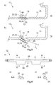
- FIG. 1a is a first embodiment of a proposed trim component 10 1 shown in principle with reference to a sectional view.
- the trim component 10 1 has a wall 12 which separates an interior space 14 from an exterior area 16.
- the wall 12 is penetrated by a passage opening 18.
- the cladding component 10 1 has a lighting device 20, which in the example shown comprises an approximately tubular, rigid optical waveguide 22.
- the lighting device 20 also has fixing means, not shown, with which the light guide 22 in the cladding component 10 1 is fastened.
- the illumination device 20 comprises coupling elements, not shown, with which the light generated by a light source, not shown, can be coupled into the light guide 22.
- the light guide 22 extends along the through hole 18 and partially protrudes into the through hole 18.
- the cladding component 10 1 has a seal 24, which fills the free space between the wall 12 and the light guide 22 and thus seals the passage opening 18.
- the light guide 22 has a coupling-out section 26 which, for example, comprises a number of notches 28 which, starting from a surface 30 of the light guide 22, project into the interior of the light guide 22.
- the coupling-out section 26 comprises a number of bulges.
- the notches 28 and the bulges cause a portion of the light which is coupled from the light source into the light guide 22 in the outcoupling section 26, which extends up to a portion of the surface 30 opposite the notches 28, to exit the light guide 22 radially
- the lateral boundaries of the outcoupling section 26 are indicated by the dashed lines L 1 and L 2 .
- the direction along which the light exits radially from the light guide 22 is indicated by the arrow P 1 .
- FIG. 1a is the lighting device 20 in the open position in which the light guide 22 assumes a rotational position in which the radially emerging light can pass through the through hole 18.
- the passage opening 18 is not vertical, but based on the in FIG. 1a Selected representation passes approximately at an angle of 45 ° to the bottom right. In this way, it is achieved that not only the surroundings of the vehicle located directly below the through-opening 18 are illuminated, but also that environment which is arranged laterally from the through-opening 18 and outside the vehicle is. Thus, the illuminated environment is increased, so that disturbing objects such as stones or puddles can be better identified laterally from or behind the vehicle.
- the light guide 22 has a protective layer 32, which is arranged in the example shown on the surface 30 of the light guide 22 and the surface 30 sweeps over partially.
- the protective layer 32 is arranged so that it extends into the outgoing coupling section 26 in the open position of the illumination device 20, but not beyond the seal 24 into the passage opening 18. As a result, the protective layer 32 does not disturb the radially outgoing light as it passes through the through-hole 18.
- the coupling-out portion 26 and the protective layer 32 may be arranged so that the protective layer 32 terminates at the lateral boundaries of the coupling-out portion 26.
- FIG. 1b is the lighting device 20 of in FIG. 1a illustrated embodiment of the trim component 10 1 in the closed position.
- the illumination device 20 is thereby brought into the closed position, that the light guide 22 with an adjusting device 34, not shown here (see. FIGS. 5a-c ) is rotated starting from the open position in the direction shown by the arrow P 2 direction.
- This ensures that the protective layer 32 is rotated in the through hole 18 and closes it.
- the light guide 22 in the closed position the light which emerges radially out of the light guide 22 in the coupling-out section 26, the through-hole 18 no longer happen.
- FIGS. 2a and 2b is a second embodiment of the proposed trim component 10 2 shown by a schematic sectional view.
- the structure of the trim component 10 2 according to the second embodiment corresponds in many parts to that of the first embodiment, but the light guide 22 is surrounded by a tubular sleeve 36.
- the sleeve 36 has a transparent section 38 and the protective layer 32 already explained above.
- the sleeve 36 is arranged so that the light which leaves the light guide 22 in the outcoupling section 26 radially, the light-transmissive portion 38 of the sleeve 36 and then the passage opening 18 can pass.
- the direction in which the light passes through the passage opening 18 is indicated by the arrow P 3 and corresponds to the direction in which the light leaves the lining component 10 1 according to the first embodiment.
- the sleeve 36 is rotated by means of the adjuster 34, also not shown, starting from the open position in the direction indicated by the arrow P 4 direction.
- the protective layer 32 closes in the closed position, the passage opening 18, so that the light while leaving the optical fiber 22 in the coupling-out section 26 radially, but can not pass through the sleeve 36. Accordingly, the optical fiber 22 itself need not be rotated, and it is quite possible to rotate the optical fiber 22 together with the sleeve 36.
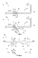
- FIG. 3a is a third embodiment of the cladding component 10 3 of the invention shown by a basic sectional view in the closed position.
- the passage opening 18 is closed by a closure means 40, which is designed as a flap 42.
- the flap 42 is rotatably mounted on the wall 12 of the trim component 10 3 and can in the in FIG. 3a shown closed position are biased, including a torsion spring, not shown, can be used.
- the light guide 22 on eccentric portions 44 which act similar to cams on the flap 42. If now the light guide 22 is rotated along the direction indicated by the arrow P 5 , the closure means 40 is opened against the biasing force of the torsion spring.
- the light which leaves the light guide 22 radially, can now leave the passage opening 18 through a gap 46 released by the flap 42.
- the flap 42 may have a reflective layer 48 on its side facing the interior 14.
- the beam path effected thereby is represented by the arrow P 6 .
- the flap 42 may have the protective layer 32 already explained above, which may for example be dirt-repellent or specially hardened, in order to protect the flap 42 itself against contamination or damage. In this way it can be ensured that the flap 42 can be moved from the closed position to the open position and back even in the case of greater contamination of the outer wall surface of the lining component 10 3 and is not blocked by the dirt.
- FIG. 4a is the light guide 22, which is used in the third embodiment of the trim component 10 3 , based a schematic representation shown. It can be seen that the eccentric sections 44 of the light guide 22 are arranged outside the outcoupling section 26. However, this does not necessarily have to be the case since the eccentric sections 44 can also be made transparent, so that the light which leaves the optical waveguide 22 radially in the outcoupling section 26 can also pass through the eccentric sections 44.
- FIG. 4b and 4c show the in FIG. 4a illustrated light guide 22 along the cutting planes AA and BB.
- the eccentric portion 44 of the light guide 22 is clearly visible while in Figure 4c the outcoupling portion 26 and the notches 28 or bulges can be seen.
- FIG. 5a is a fourth embodiment of the cladding component 10 5 according to the invention based on a basic sectional view in the closed position and in FIG. 5b shown in the open position, wherein the fourth embodiment which is similar in many parts to the third embodiment.
- the reflective layer 48 is not on the flap 42, but is disposed on the eccentric portions 44 and the light guide 22, the reflective layer being located particularly on the side of the eccentric portions 44 which engage the flap 42 comes into contact.
- the light leaves the optical fiber 22 via the eccentric portions 44.
- the beam path thereby effected is substantially the same as that obtained with the third embodiment.
- the extraction portions 26 and the notches 28 or the bulges must be disposed within the eccentric portions 44 so as to be the light can leave the light guide 22 via the eccentric portions 44.
- FIGS. 7a-c a fifth embodiment of the proposed trim component 10 5 is shown with reference to a plan view. It can be seen that the passage openings 18 have an approximately rectangular cross-section, with the longer edges extending approximately perpendicular to the light guide 22.
- the light guide 22 extends slightly above the shorter, in the FIGS. 7a-c Upper edges of the through holes 18 and is axially displaceable along the direction indicated by the arrow P 7 , including the adjusting device 34 shown here only in principle.
- the adjusting device 34 may have two cable winches 50, which are each connected via a cable 52 with the illumination device 20 and these can move along the direction indicated by the arrow P 7 back and forth.
- the light guide 22 has a number of protective layers 32, which are arranged spatially separated from each other on the surface 30 of the light guide 22 and sweep them more or less far. In the spaces between the protective layers 32, a number of the coupling-out portions 26 is arranged.
- the lighting device 20 is in the closed position. It can be seen that the protective layer 32 covers the passage openings 18. However, the light guide 22 is moved away from the closed position with the adjusting 34 in the open position, for example in the in the FIGS. 7b or in FIG. 7c shown positions, the through holes 18 are no longer covered by the protective layers 32. Rather, the passage openings 18 are now covered more by the coupling-out sections 26. Consequently, the light which the light guide 22 in the Departing section 26 radially leaves, now also pass through the through holes 18 and thus illuminate the environment of the vehicle.
- the passage openings 18 and the light guide 22 are arranged on a separate wall portion 54 which is connected in a manner not shown in detail with the remaining wall 12 of the trim component 10 5 .
- the dimensions of the trim component 10 need not be changed to provide it with the light source 34 and the illumination device 26. The additional design effort therefore remains very low.
- the additional weight caused by the light source 34 and the illumination device 26 is approximately 300 g, which is within reasonable limits.
- the illuminated area is approximately 1200 to 1400 mm in the longitudinal direction of the vehicle and approximately 400 to 600 mm in the transverse direction of the vehicle.
- the length of the through openings 18 can assume values of 10 to 300 mm and the distance between two adjacent through openings can be between 5 and 25 mm.
- the width of the through openings 18 can assume values between 5 and 25 mm.
- the illuminance is approximately between 4 and 50 lx (lux) on the floor.
- the power consumption of an LED board encompassed by the light source is preferably 16 W (watts).
- the light guide 22 may, for example, have a length of 650 to 900 mm and a diameter of 4 to 5.5 mm.
Landscapes
- Engineering & Computer Science (AREA)
- Mechanical Engineering (AREA)
- Arrangements Of Lighting Devices For Vehicle Interiors, Mounting And Supporting Thereof, Circuits Therefore (AREA)
Priority Applications (1)
| Application Number | Priority Date | Filing Date | Title |
|---|---|---|---|
| EP15181728.5A EP3144182B1 (fr) | 2015-08-20 | 2015-08-20 | Composant d'habillage pour véhicule et véhicule associé |
Applications Claiming Priority (1)
| Application Number | Priority Date | Filing Date | Title |
|---|---|---|---|
| EP15181728.5A EP3144182B1 (fr) | 2015-08-20 | 2015-08-20 | Composant d'habillage pour véhicule et véhicule associé |
Publications (2)
| Publication Number | Publication Date |
|---|---|
| EP3144182A1 true EP3144182A1 (fr) | 2017-03-22 |
| EP3144182B1 EP3144182B1 (fr) | 2021-04-28 |
Family
ID=53900775
Family Applications (1)
| Application Number | Title | Priority Date | Filing Date |
|---|---|---|---|
| EP15181728.5A Active EP3144182B1 (fr) | 2015-08-20 | 2015-08-20 | Composant d'habillage pour véhicule et véhicule associé |
Country Status (1)
| Country | Link |
|---|---|
| EP (1) | EP3144182B1 (fr) |
Cited By (6)
| Publication number | Priority date | Publication date | Assignee | Title |
|---|---|---|---|---|
| WO2019034493A1 (fr) * | 2017-08-18 | 2019-02-21 | Audi Ag | Dispositif d'éclairage d'un marchepied mobile pour un véhicule automobile |
| FR3075709A1 (fr) * | 2017-12-22 | 2019-06-28 | Psa Automobiles Sa | Vehicule automobile comportant un systeme de projection de motifs lumineux au sol |
| DE102018211996A1 (de) * | 2018-07-18 | 2020-01-23 | Röchling Automotive SE & Co. KG | Luftklappenvorrichtung mit integrierten Lichtleitern für ein Kraftfahrzeug |
| EP3770016A1 (fr) | 2019-07-24 | 2021-01-27 | Motherson Innovations Company Limited | Dispositif d'éclairage pour un moyen de transport des personnes et / ou des marchandises ou pour un composant de revêtement externe ou interne d'un moyen de transport des personnes et / ou des marchandises, composant de revêtement externe ou interne ainsi que moyen de transport des personnes et / ou des marchandises doté d'un tel dispositif d'éclairage |
| EP3770015A1 (fr) | 2019-07-24 | 2021-01-27 | Motherson Innovations Company Limited | Dispositif d'éclairage pour un moyen de transport des personnes et / ou des marchandises ou pour un composant de revêtement externe ou interne d'un moyen de transport des personnes et / ou des marchandises, composant de revêtement externe ou interne ainsi que moyen de transport des personnes et / ou des marchandises doté d'un tel dispositif d'éclairage |
| DE102019212552A1 (de) * | 2019-08-22 | 2021-02-25 | Volkswagen Aktiengesellschaft | Vorrichtung zum Freigeben, teilweise Freigeben und Verschließen einer Durchströmungsöffnung, Kühleinrichtung |
Families Citing this family (2)
| Publication number | Priority date | Publication date | Assignee | Title |
|---|---|---|---|---|
| DE102022209763A1 (de) * | 2022-09-16 | 2024-03-21 | Magna Exteriors Gmbh | Verkleidungsteil für ein Kraftfahrzeug |
| DE102023003233A1 (de) * | 2023-08-05 | 2025-02-06 | Mercedes-Benz Group AG | Beleuchtungsanordnung für ein Fahrzeug |
Citations (8)
| Publication number | Priority date | Publication date | Assignee | Title |
|---|---|---|---|---|
| DE4311359A1 (de) * | 1992-04-07 | 1993-10-14 | Bridgestone Corp Tokio Tokyo | Lichtleiterschlauch |
| FR2764852A1 (fr) * | 1997-06-19 | 1998-12-24 | Peugeot | Agencement pour feu de signalisation supplementaire de vehicule automobile |
| US6250785B1 (en) * | 1999-09-10 | 2001-06-26 | Algonquin Industries International, Inc. | Light tube running board lighting |
| DE102006014561B3 (de) * | 2006-03-29 | 2007-10-11 | Audi Ag | Kraftfahrzeug |
| DE102009039038A1 (de) * | 2009-08-28 | 2011-03-03 | Bayerische Motoren Werke Aktiengesellschaft | Kühlergrill und Hybridfahrzeug |
| US8235568B2 (en) | 2010-02-26 | 2012-08-07 | Nissan North America, Inc. | Security lighting for a vehicle |
| DE102011115208A1 (de) * | 2011-09-28 | 2013-03-28 | Daimler Ag | Kraftfahrzeugvorrichtung mit einer verdrehbaren Multifunktionskonsole |
| EP2703218A2 (fr) * | 2012-08-31 | 2014-03-05 | SL Corporation | Phare pour véhicule et son procédé de commande |
-
2015
- 2015-08-20 EP EP15181728.5A patent/EP3144182B1/fr active Active
Patent Citations (8)
| Publication number | Priority date | Publication date | Assignee | Title |
|---|---|---|---|---|
| DE4311359A1 (de) * | 1992-04-07 | 1993-10-14 | Bridgestone Corp Tokio Tokyo | Lichtleiterschlauch |
| FR2764852A1 (fr) * | 1997-06-19 | 1998-12-24 | Peugeot | Agencement pour feu de signalisation supplementaire de vehicule automobile |
| US6250785B1 (en) * | 1999-09-10 | 2001-06-26 | Algonquin Industries International, Inc. | Light tube running board lighting |
| DE102006014561B3 (de) * | 2006-03-29 | 2007-10-11 | Audi Ag | Kraftfahrzeug |
| DE102009039038A1 (de) * | 2009-08-28 | 2011-03-03 | Bayerische Motoren Werke Aktiengesellschaft | Kühlergrill und Hybridfahrzeug |
| US8235568B2 (en) | 2010-02-26 | 2012-08-07 | Nissan North America, Inc. | Security lighting for a vehicle |
| DE102011115208A1 (de) * | 2011-09-28 | 2013-03-28 | Daimler Ag | Kraftfahrzeugvorrichtung mit einer verdrehbaren Multifunktionskonsole |
| EP2703218A2 (fr) * | 2012-08-31 | 2014-03-05 | SL Corporation | Phare pour véhicule et son procédé de commande |
Cited By (7)
| Publication number | Priority date | Publication date | Assignee | Title |
|---|---|---|---|---|
| WO2019034493A1 (fr) * | 2017-08-18 | 2019-02-21 | Audi Ag | Dispositif d'éclairage d'un marchepied mobile pour un véhicule automobile |
| FR3075709A1 (fr) * | 2017-12-22 | 2019-06-28 | Psa Automobiles Sa | Vehicule automobile comportant un systeme de projection de motifs lumineux au sol |
| DE102018211996A1 (de) * | 2018-07-18 | 2020-01-23 | Röchling Automotive SE & Co. KG | Luftklappenvorrichtung mit integrierten Lichtleitern für ein Kraftfahrzeug |
| EP3770016A1 (fr) | 2019-07-24 | 2021-01-27 | Motherson Innovations Company Limited | Dispositif d'éclairage pour un moyen de transport des personnes et / ou des marchandises ou pour un composant de revêtement externe ou interne d'un moyen de transport des personnes et / ou des marchandises, composant de revêtement externe ou interne ainsi que moyen de transport des personnes et / ou des marchandises doté d'un tel dispositif d'éclairage |
| EP3770015A1 (fr) | 2019-07-24 | 2021-01-27 | Motherson Innovations Company Limited | Dispositif d'éclairage pour un moyen de transport des personnes et / ou des marchandises ou pour un composant de revêtement externe ou interne d'un moyen de transport des personnes et / ou des marchandises, composant de revêtement externe ou interne ainsi que moyen de transport des personnes et / ou des marchandises doté d'un tel dispositif d'éclairage |
| DE102019212552A1 (de) * | 2019-08-22 | 2021-02-25 | Volkswagen Aktiengesellschaft | Vorrichtung zum Freigeben, teilweise Freigeben und Verschließen einer Durchströmungsöffnung, Kühleinrichtung |
| DE102019212552B4 (de) | 2019-08-22 | 2022-08-11 | Volkswagen Aktiengesellschaft | Vorrichtung zum Freigeben, teilweise Freigeben und Verschließen einer Durchströmungsöffnung, Kühleinrichtung |
Also Published As
| Publication number | Publication date |
|---|---|
| EP3144182B1 (fr) | 2021-04-28 |
Similar Documents
| Publication | Publication Date | Title |
|---|---|---|
| EP3144182B1 (fr) | Composant d'habillage pour véhicule et véhicule associé | |
| EP3013642B1 (fr) | Véhicule automobile | |
| EP1914118B1 (fr) | Miroir extérieur avec moyen lumineux | |
| EP3368370B1 (fr) | Véhicule automobile et dispositif d'illumination de l'environnement d'un véhicule | |
| DE102017007847B4 (de) | Beleuchtungsvorrichtung für ein Fahrzeug | |
| EP3245084B1 (fr) | Baguette décorative éclairée | |
| DE10131735B4 (de) | Parksperre für Fahrzeuggetriebe | |
| EP2525029B1 (fr) | Dispositif d'actionnement pour une pièce mobile d'un véhicule automobile | |
| WO2017144247A1 (fr) | Véhicule à moteur doté d'un dispositif d'éclairage périphérique | |
| EP0493774B1 (fr) | Porte pour cabine de véhicule | |
| DE102010045070A1 (de) | Leuchtanordnung in einem Fahrzeug | |
| DE20021312U1 (de) | Leuchte für Fahrzeuge, vorzugsweise für Kraftfahrzeuge | |
| WO2016055467A1 (fr) | Élément rapporté extérieur, véhicule à moteur doté d'un élément rapporté extérieur ainsi que procédé de commande d'un élément rapporté extérieur | |
| DE102011112835A1 (de) | Beleuchtungsanordnung für einen Kraftwagen | |
| EP1923266A1 (fr) | Rétroviseur extérieur pour véhicules | |
| DE19929422A1 (de) | Kraftfahrzeug | |
| EP3132972B1 (fr) | Composant d'habillage pour véhicule | |
| EP4680493A1 (fr) | Agencement de phare pour un véhicule | |
| EP3616988A1 (fr) | Dispositif d'éclairage pour un moyen de transport de personnes et / ou marchandises, composant d'habillage pour un moyen de transport de personnes et / ou marchandises doté d'un tel dispositif d'éclairage ainsi que moyen de transport de personnes et / ou marchandises doté d'un tel composant d'habillage | |
| DE102006014561B3 (de) | Kraftfahrzeug | |
| DE102018005590A1 (de) | Vorrichtung zur Betätigung einer Fahrzeugtür | |
| DE10217490B4 (de) | Kraftfahrzeug mit wenigstens einer Bremsleuchte in einem oberen Heckscheiben-Randbereich | |
| EP1876047A2 (fr) | Porte de véhicule automobile dotée d'une poignée intérieure | |
| EP0829599B1 (fr) | Dispositif pour manoeuvrer des portes, hayons, couvercles de coffres ou similaires des voitures | |
| DE102018220102A1 (de) | Leseleuchte im Innenraum eines Kraftfahrzeugs |
Legal Events
| Date | Code | Title | Description |
|---|---|---|---|
| PUAI | Public reference made under article 153(3) epc to a published international application that has entered the european phase |
Free format text: ORIGINAL CODE: 0009012 |
|
| STAA | Information on the status of an ep patent application or granted ep patent |
Free format text: STATUS: THE APPLICATION HAS BEEN PUBLISHED |
|
| AK | Designated contracting states |
Kind code of ref document: A1 Designated state(s): AL AT BE BG CH CY CZ DE DK EE ES FI FR GB GR HR HU IE IS IT LI LT LU LV MC MK MT NL NO PL PT RO RS SE SI SK SM TR |
|
| AX | Request for extension of the european patent |
Extension state: BA ME |
|
| STAA | Information on the status of an ep patent application or granted ep patent |
Free format text: STATUS: REQUEST FOR EXAMINATION WAS MADE |
|
| 17P | Request for examination filed |
Effective date: 20170504 |
|
| RBV | Designated contracting states (corrected) |
Designated state(s): AL AT BE BG CH CY CZ DE DK EE ES FI FR GB GR HR HU IE IS IT LI LT LU LV MC MK MT NL NO PL PT RO RS SE SI SK SM TR |
|
| STAA | Information on the status of an ep patent application or granted ep patent |
Free format text: STATUS: EXAMINATION IS IN PROGRESS |
|
| 17Q | First examination report despatched |
Effective date: 20200422 |
|
| GRAP | Despatch of communication of intention to grant a patent |
Free format text: ORIGINAL CODE: EPIDOSNIGR1 |
|
| STAA | Information on the status of an ep patent application or granted ep patent |
Free format text: STATUS: GRANT OF PATENT IS INTENDED |
|
| RIC1 | Information provided on ipc code assigned before grant |
Ipc: B60Q 1/26 20060101ALI20201109BHEP Ipc: B60Q 1/24 20060101AFI20201109BHEP Ipc: B60Q 3/64 20170101ALI20201109BHEP Ipc: B60Q 3/217 20170101ALI20201109BHEP Ipc: B60Q 1/32 20060101ALI20201109BHEP |
|
| INTG | Intention to grant announced |
Effective date: 20201211 |
|
| GRAS | Grant fee paid |
Free format text: ORIGINAL CODE: EPIDOSNIGR3 |
|
| GRAA | (expected) grant |
Free format text: ORIGINAL CODE: 0009210 |
|
| STAA | Information on the status of an ep patent application or granted ep patent |
Free format text: STATUS: THE PATENT HAS BEEN GRANTED |
|
| AK | Designated contracting states |
Kind code of ref document: B1 Designated state(s): AL AT BE BG CH CY CZ DE DK EE ES FI FR GB GR HR HU IE IS IT LI LT LU LV MC MK MT NL NO PL PT RO RS SE SI SK SM TR |
|
| REG | Reference to a national code |
Ref country code: GB Ref legal event code: FG4D Free format text: NOT ENGLISH |
|
| REG | Reference to a national code |
Ref country code: CH Ref legal event code: EP |
|
| REG | Reference to a national code |
Ref country code: DE Ref legal event code: R096 Ref document number: 502015014620 Country of ref document: DE |
|
| REG | Reference to a national code |
Ref country code: AT Ref legal event code: REF Ref document number: 1386712 Country of ref document: AT Kind code of ref document: T Effective date: 20210515 |
|
| REG | Reference to a national code |
Ref country code: IE Ref legal event code: FG4D Free format text: LANGUAGE OF EP DOCUMENT: GERMAN |
|
| REG | Reference to a national code |
Ref country code: LT Ref legal event code: MG9D |
|
| PG25 | Lapsed in a contracting state [announced via postgrant information from national office to epo] |
Ref country code: HR Free format text: LAPSE BECAUSE OF FAILURE TO SUBMIT A TRANSLATION OF THE DESCRIPTION OR TO PAY THE FEE WITHIN THE PRESCRIBED TIME-LIMIT Effective date: 20210428 Ref country code: BG Free format text: LAPSE BECAUSE OF FAILURE TO SUBMIT A TRANSLATION OF THE DESCRIPTION OR TO PAY THE FEE WITHIN THE PRESCRIBED TIME-LIMIT Effective date: 20210728 Ref country code: FI Free format text: LAPSE BECAUSE OF FAILURE TO SUBMIT A TRANSLATION OF THE DESCRIPTION OR TO PAY THE FEE WITHIN THE PRESCRIBED TIME-LIMIT Effective date: 20210428 Ref country code: LT Free format text: LAPSE BECAUSE OF FAILURE TO SUBMIT A TRANSLATION OF THE DESCRIPTION OR TO PAY THE FEE WITHIN THE PRESCRIBED TIME-LIMIT Effective date: 20210428 Ref country code: NL Free format text: LAPSE BECAUSE OF FAILURE TO SUBMIT A TRANSLATION OF THE DESCRIPTION OR TO PAY THE FEE WITHIN THE PRESCRIBED TIME-LIMIT Effective date: 20210428 |
|
| PG25 | Lapsed in a contracting state [announced via postgrant information from national office to epo] |
Ref country code: NO Free format text: LAPSE BECAUSE OF FAILURE TO SUBMIT A TRANSLATION OF THE DESCRIPTION OR TO PAY THE FEE WITHIN THE PRESCRIBED TIME-LIMIT Effective date: 20210728 Ref country code: PL Free format text: LAPSE BECAUSE OF FAILURE TO SUBMIT A TRANSLATION OF THE DESCRIPTION OR TO PAY THE FEE WITHIN THE PRESCRIBED TIME-LIMIT Effective date: 20210428 Ref country code: PT Free format text: LAPSE BECAUSE OF FAILURE TO SUBMIT A TRANSLATION OF THE DESCRIPTION OR TO PAY THE FEE WITHIN THE PRESCRIBED TIME-LIMIT Effective date: 20210830 Ref country code: ES Free format text: LAPSE BECAUSE OF FAILURE TO SUBMIT A TRANSLATION OF THE DESCRIPTION OR TO PAY THE FEE WITHIN THE PRESCRIBED TIME-LIMIT Effective date: 20210428 Ref country code: RS Free format text: LAPSE BECAUSE OF FAILURE TO SUBMIT A TRANSLATION OF THE DESCRIPTION OR TO PAY THE FEE WITHIN THE PRESCRIBED TIME-LIMIT Effective date: 20210428 Ref country code: SE Free format text: LAPSE BECAUSE OF FAILURE TO SUBMIT A TRANSLATION OF THE DESCRIPTION OR TO PAY THE FEE WITHIN THE PRESCRIBED TIME-LIMIT Effective date: 20210428 Ref country code: IS Free format text: LAPSE BECAUSE OF FAILURE TO SUBMIT A TRANSLATION OF THE DESCRIPTION OR TO PAY THE FEE WITHIN THE PRESCRIBED TIME-LIMIT Effective date: 20210828 Ref country code: GR Free format text: LAPSE BECAUSE OF FAILURE TO SUBMIT A TRANSLATION OF THE DESCRIPTION OR TO PAY THE FEE WITHIN THE PRESCRIBED TIME-LIMIT Effective date: 20210729 Ref country code: LV Free format text: LAPSE BECAUSE OF FAILURE TO SUBMIT A TRANSLATION OF THE DESCRIPTION OR TO PAY THE FEE WITHIN THE PRESCRIBED TIME-LIMIT Effective date: 20210428 |
|
| REG | Reference to a national code |
Ref country code: NL Ref legal event code: MP Effective date: 20210428 |
|
| PG25 | Lapsed in a contracting state [announced via postgrant information from national office to epo] |
Ref country code: RO Free format text: LAPSE BECAUSE OF FAILURE TO SUBMIT A TRANSLATION OF THE DESCRIPTION OR TO PAY THE FEE WITHIN THE PRESCRIBED TIME-LIMIT Effective date: 20210428 Ref country code: DK Free format text: LAPSE BECAUSE OF FAILURE TO SUBMIT A TRANSLATION OF THE DESCRIPTION OR TO PAY THE FEE WITHIN THE PRESCRIBED TIME-LIMIT Effective date: 20210428 Ref country code: EE Free format text: LAPSE BECAUSE OF FAILURE TO SUBMIT A TRANSLATION OF THE DESCRIPTION OR TO PAY THE FEE WITHIN THE PRESCRIBED TIME-LIMIT Effective date: 20210428 Ref country code: CZ Free format text: LAPSE BECAUSE OF FAILURE TO SUBMIT A TRANSLATION OF THE DESCRIPTION OR TO PAY THE FEE WITHIN THE PRESCRIBED TIME-LIMIT Effective date: 20210428 Ref country code: SM Free format text: LAPSE BECAUSE OF FAILURE TO SUBMIT A TRANSLATION OF THE DESCRIPTION OR TO PAY THE FEE WITHIN THE PRESCRIBED TIME-LIMIT Effective date: 20210428 Ref country code: SK Free format text: LAPSE BECAUSE OF FAILURE TO SUBMIT A TRANSLATION OF THE DESCRIPTION OR TO PAY THE FEE WITHIN THE PRESCRIBED TIME-LIMIT Effective date: 20210428 |
|
| REG | Reference to a national code |
Ref country code: DE Ref legal event code: R097 Ref document number: 502015014620 Country of ref document: DE |
|
| PLBE | No opposition filed within time limit |
Free format text: ORIGINAL CODE: 0009261 |
|
| STAA | Information on the status of an ep patent application or granted ep patent |
Free format text: STATUS: NO OPPOSITION FILED WITHIN TIME LIMIT |
|
| REG | Reference to a national code |
Ref country code: CH Ref legal event code: PL |
|
| PG25 | Lapsed in a contracting state [announced via postgrant information from national office to epo] |
Ref country code: MC Free format text: LAPSE BECAUSE OF FAILURE TO SUBMIT A TRANSLATION OF THE DESCRIPTION OR TO PAY THE FEE WITHIN THE PRESCRIBED TIME-LIMIT Effective date: 20210428 |
|
| 26N | No opposition filed |
Effective date: 20220131 |
|
| REG | Reference to a national code |
Ref country code: BE Ref legal event code: MM Effective date: 20210831 |
|
| PG25 | Lapsed in a contracting state [announced via postgrant information from national office to epo] |
Ref country code: LI Free format text: LAPSE BECAUSE OF NON-PAYMENT OF DUE FEES Effective date: 20210831 Ref country code: CH Free format text: LAPSE BECAUSE OF NON-PAYMENT OF DUE FEES Effective date: 20210831 |
|
| PG25 | Lapsed in a contracting state [announced via postgrant information from national office to epo] |
Ref country code: IS Free format text: LAPSE BECAUSE OF FAILURE TO SUBMIT A TRANSLATION OF THE DESCRIPTION OR TO PAY THE FEE WITHIN THE PRESCRIBED TIME-LIMIT Effective date: 20210828 Ref country code: LU Free format text: LAPSE BECAUSE OF NON-PAYMENT OF DUE FEES Effective date: 20210820 Ref country code: AL Free format text: LAPSE BECAUSE OF FAILURE TO SUBMIT A TRANSLATION OF THE DESCRIPTION OR TO PAY THE FEE WITHIN THE PRESCRIBED TIME-LIMIT Effective date: 20210428 |
|
| PG25 | Lapsed in a contracting state [announced via postgrant information from national office to epo] |
Ref country code: IT Free format text: LAPSE BECAUSE OF FAILURE TO SUBMIT A TRANSLATION OF THE DESCRIPTION OR TO PAY THE FEE WITHIN THE PRESCRIBED TIME-LIMIT Effective date: 20210428 Ref country code: IE Free format text: LAPSE BECAUSE OF NON-PAYMENT OF DUE FEES Effective date: 20210820 Ref country code: BE Free format text: LAPSE BECAUSE OF NON-PAYMENT OF DUE FEES Effective date: 20210831 |
|
| REG | Reference to a national code |
Ref country code: AT Ref legal event code: MM01 Ref document number: 1386712 Country of ref document: AT Kind code of ref document: T Effective date: 20210820 |
|
| PG25 | Lapsed in a contracting state [announced via postgrant information from national office to epo] |
Ref country code: AT Free format text: LAPSE BECAUSE OF NON-PAYMENT OF DUE FEES Effective date: 20210820 |
|
| PG25 | Lapsed in a contracting state [announced via postgrant information from national office to epo] |
Ref country code: HU Free format text: LAPSE BECAUSE OF FAILURE TO SUBMIT A TRANSLATION OF THE DESCRIPTION OR TO PAY THE FEE WITHIN THE PRESCRIBED TIME-LIMIT; INVALID AB INITIO Effective date: 20150820 |
|
| P01 | Opt-out of the competence of the unified patent court (upc) registered |
Effective date: 20230427 |
|
| PG25 | Lapsed in a contracting state [announced via postgrant information from national office to epo] |
Ref country code: CY Free format text: LAPSE BECAUSE OF FAILURE TO SUBMIT A TRANSLATION OF THE DESCRIPTION OR TO PAY THE FEE WITHIN THE PRESCRIBED TIME-LIMIT Effective date: 20210428 |
|
| PG25 | Lapsed in a contracting state [announced via postgrant information from national office to epo] |
Ref country code: MK Free format text: LAPSE BECAUSE OF FAILURE TO SUBMIT A TRANSLATION OF THE DESCRIPTION OR TO PAY THE FEE WITHIN THE PRESCRIBED TIME-LIMIT Effective date: 20210428 |
|
| PG25 | Lapsed in a contracting state [announced via postgrant information from national office to epo] |
Ref country code: TR Free format text: LAPSE BECAUSE OF FAILURE TO SUBMIT A TRANSLATION OF THE DESCRIPTION OR TO PAY THE FEE WITHIN THE PRESCRIBED TIME-LIMIT Effective date: 20210428 |
|
| PG25 | Lapsed in a contracting state [announced via postgrant information from national office to epo] |
Ref country code: MT Free format text: LAPSE BECAUSE OF FAILURE TO SUBMIT A TRANSLATION OF THE DESCRIPTION OR TO PAY THE FEE WITHIN THE PRESCRIBED TIME-LIMIT Effective date: 20210428 |
|
| PGFP | Annual fee paid to national office [announced via postgrant information from national office to epo] |
Ref country code: DE Payment date: 20250819 Year of fee payment: 11 |
|
| PGFP | Annual fee paid to national office [announced via postgrant information from national office to epo] |
Ref country code: GB Payment date: 20250822 Year of fee payment: 11 |
|
| PGFP | Annual fee paid to national office [announced via postgrant information from national office to epo] |
Ref country code: FR Payment date: 20250821 Year of fee payment: 11 |