EP3146155B1 - Konstruktionselement zur erzeugung eines tunnels, tunnel mit solch einem element und verfahren zur konstruktion solch eines elements und solch eines tunnels - Google Patents
Konstruktionselement zur erzeugung eines tunnels, tunnel mit solch einem element und verfahren zur konstruktion solch eines elements und solch eines tunnels Download PDFInfo
- Publication number
- EP3146155B1 EP3146155B1 EP15732774.3A EP15732774A EP3146155B1 EP 3146155 B1 EP3146155 B1 EP 3146155B1 EP 15732774 A EP15732774 A EP 15732774A EP 3146155 B1 EP3146155 B1 EP 3146155B1
- Authority
- EP
- European Patent Office
- Prior art keywords
- layer
- tunnel
- devices
- construction element
- solid body
- Prior art date
- Legal status (The legal status is an assumption and is not a legal conclusion. Google has not performed a legal analysis and makes no representation as to the accuracy of the status listed.)
- Active
Links
Images



Classifications
-
- E—FIXED CONSTRUCTIONS
- E21—EARTH OR ROCK DRILLING; MINING
- E21D—SHAFTS; TUNNELS; GALLERIES; LARGE UNDERGROUND CHAMBERS
- E21D11/00—Lining tunnels, galleries or other underground cavities, e.g. large underground chambers; Linings therefor; Making such linings in situ, e.g. by assembling
- E21D11/04—Lining with building materials
- E21D11/08—Lining with building materials with preformed concrete slabs
-
- E—FIXED CONSTRUCTIONS
- E21—EARTH OR ROCK DRILLING; MINING
- E21D—SHAFTS; TUNNELS; GALLERIES; LARGE UNDERGROUND CHAMBERS
- E21D11/00—Lining tunnels, galleries or other underground cavities, e.g. large underground chambers; Linings therefor; Making such linings in situ, e.g. by assembling
- E21D11/04—Lining with building materials
- E21D11/05—Lining with building materials using compressible insertions
Definitions
- the invention relates to the construction of tunnels, in particular underground tunnels, and the construction elements of such tunnels.
- a cavity is generally dug underground, then a tunnel is formed in this cavity using segments.
- the segments correspond to constituent elements of an annular section of the tunnel, once assembled together.
- each precast concrete segment Before being used to build the tunnel, each precast concrete segment has a layer of compressible material, such as polyethylene foam, glued to the outer surface of the segment. But the foam is not stable and can disintegrate over time, causing a loss of its mechanical properties of compression and deformation. In addition, such foam made of synthetic material can be polluting.
- the documents US 4,363,565 And EN 2988770 disclose construction elements for the realization of a tunnel having damping systems of the prior art.
- An object of the invention consists in overcoming the drawbacks cited above and in particular in providing a means that is easy to produce and to implement for damping the convergence of a terrain exerted on a tunnel.
- a construction element for making a tunnel comprising a first incompressible layer of concrete and a second compressible layer integral with the first layer to form a one-piece prefabricated construction element configured to be integrated into a section of the tunnel.
- the second layer includes a plurality of devices each having a solid body incorporating an empty space.
- a prefabricated building element suitable for making a section of a tunnel is provided.
- Such a one-piece construction element is easy to handle and its manufacture can be controlled so as to obtain a homogeneous tunnel section, in order to control the behavior of the tunnel faced with the convergence of the terrain.
- the device voids determine the compressibility of the second layer. In other words, the empty spaces allow the terrain to converge and relieve the stresses exerted on the first layer.
- the second layer may include devices each provided with a through hole.
- the second layer can also include devices whose solid body delimits at least one closed cavity.
- the solid body of the devices can be made of ceramic.
- the solid body of the devices, according to the invention is coated with an adhesive film to secure the devices to the first layer.
- the adhesive film can be made from a mortar.
- the construction element may further comprise a third protective layer located on the second layer.
- a third protective layer located on the second layer.
- the second layer is protected in order to preserve its integrity, for example during transport of the construction element before it is placed in a section of the tunnel.
- a tunnel is proposed located inside a cavity dug in the ground, at least one section of the tunnel being made from at least one two-layer construction element as defined below.
- Each two-layer construction element may include a third layer of protection located on the second layer, and the tunnel may include an infill product occupying a delimited free space between the third layer of protection and the ground.
- the second layer is produced from a plurality of devices each having a solid body integrating an empty space.
- the second layer may include devices each provided with a through hole and/or devices whose solid body delimits at least one closed cavity.
- the method can also comprise a protection step in which a third protective layer is placed on the second layer.
- Each two-layer construction element can comprise a third protective layer located on the second layer, and a free space delimited between the third protective layer and the ground can be filled with the aid of a filling product.
- the present invention provides particular advantages in the field of tunnels, it is also applicable to any system which is made in an underground cavity and which is configured to resist the convergence of the ground, for example receptacles or partially or totally buried tanks.
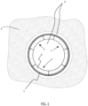
- a tunnel 1 made in a cavity 2 dug in a ground 3, in other words an underground tunnel.
- the tunnel 1 can be open and have an inverted U shape, it can also be closed and have an ovoid shape, or any other shape.
- the tunnel 1 has an overall tubular shape.
- the tunnel 1 comprises sections 4 located within the cavity 2. At least one section 4, and preferably each section 4, is made from construction elements 5 assembled together. At least one construction element 5 comprises a first incompressible layer 6 of concrete.
- the first layer 6 has the shape of a curved hexahedron.
- the construction element 5 comprises a second compressible layer 7 integral with the first layer 6 to form a prefabricated construction element 5 of the one-piece type.
- the construction element 5 is prefabricated, that is to say it is produced before the construction of the tunnel 1.
- the construction element 5 is produced beforehand, then several construction elements are assembled. construction 5 between them so as to produce a section 4 of the tunnel 1.
- the construction element 5 incorporates previously a compressible layer 7, and therefore has an integrated damping mechanical property.
- one-piece element means a movable element which retains its physical integrity and its mechanical properties during transport, for example when the element is moved from its manufacturing area to the location of section 4 of the tunnel. 1 where it is placed.
- the construction element 5 is configured to be integrated into a section 4 of the tunnel 1, and in particular into a section 4 which is in progress.
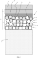
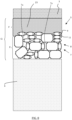
- the second layer 7 includes several devices 8, as illustrated in figure 2 And 8 , each having a solid body 9 integrating an empty space 10.
- empty space integrated in a body is meant a closed or open cavity delimited by the body of the device.
- the second layer 7 is compressible, that is to say it can deform during the convergence of the terrain 3.
- the devices 8 have a deformable solid body 9. That is to say that the devices can deform, by breaking or bending, thanks in particular to their empty space 10, to allow the deformation of the second layer 7.
- the second layer 7 comprises interstices 7a, that is to say empty spaces, located between the devices 8.
- a compressible layer 7 having a residual volume, constituted by the sum of the empty spaces of each of the devices 8 and of the interstices 7a, which offers a damping property of the convergence of terrain 3.
- terrain 3 exerts an initial convergence pressure on tunnel 1. Due to the movements of terrain 3, it will tend to converge towards the inside of the cavity 2.
- the deformation of the devices 8 will allow a progressive approach of the ground 3 towards the inside of the tunnel 1, until the ground 3 occupies a state of equilibrium. In the equilibrium state, the convergence pressure is lower than the initial pressure.
- the second compressible layer 7 therefore makes it possible to dampen the convergence of the ground up to a state of equilibrium for which the convergence pressure is supported by the construction element 5, that is to say that the first incompressible layer 6 does not break under convergence pressure at equilibrium.
- devices 8 can be made of ceramic.
- the ceramic offers good resistance while being breakable to effectively dampen the convergence of the terrain 3.
- the bodies 9 of the devices 8 break, the terrain 3 can converge towards the interior of the tunnel 1.
- the devices 8 can also be made of glass, cement, or mortar which are, like ceramics, materials that can be broken under the effect of the convergence of the ground 3.
- the devices 8 can be made of metal, or plastic material, deformable .
- the devices 8 When the devices 8 have a deformable body, they also make it possible to damp the convergence of the terrain.
- devices 8, of the second compressible layer 7 each comprise a body 9 provided with a through hole 10 (illustrated later in figures 4 to 7 ).
- the construction element 5 integrated in a section of a tunnel.
- the prefabricated construction element 5 is in one piece and comprises the first layer 6 of concrete and the second compressible layer 7 formed by the devices 8.
- the construction element 5 forms a segment with a compressible part 7 configured to produce an annular section of the tunnel 1.
- the thickness E of the second layer 7 is chosen according to the damping of the convergence of the terrain 3 that one wishes to obtain.
- the thickness E is chosen according to the displacement of the ground 3, relative to its initial position, which can be supported by the construction element 5.
- the ground 3 In the initial position, the ground 3 is at an initial distance Gi of the outer surface of the first layer 6.
- the initial distance Gi corresponds to the sum between the initial thickness E of the second layer 7, the thickness of the third protective layer 12, and the thickness of the free space F
- the thickness E also depends on the compressibility of the devices 8.
- the devices 8 are coated with an adhesive film 11 to secure them to the first layer 6.
- the adhesive layer 11 makes it possible to secure the devices 8 between them and to the first layer of concrete 6.
- the construction element 5 is in one piece and it is movable to be integrated into the section of the tunnel during its formation.
- the adhesive film 11 preferably comprises mortar which adheres effectively to the first layer of concrete 6.
- the mortar comprises, for its part, cement, sand and water.
- the mortar is hardenable and hardens to bond the devices 8 together and allow the devices to adhere to the first layer 6.
- the adhesive film 11 coats the external surface of the device 8, without obstructing the through-hole 10.
- Other adhesive elements can be used to coat the devices 8, for example an epoxy resin-based glue, etc. .
- the construction element 5 can comprise a third protective layer 12 located on the second layer 7. More particularly, the third protective layer 12 is a thin layer compared to the first and second layers 6, 7. , the third protective layer 12 is bonded to the second layer 7 to make it mechanically integral with the second layer 7.
- the third protective layer 12 protects the second layer 7 from shocks, for example during handling of the element of construction 5, in order to prevent the bodies 9 of the devices 8 from breaking, in particular those located on the periphery of the construction element 5.
- a free space F is generally created between the internal surface of the cavity and the external surface of the tunnel section, i.e. the external surface of the building element 5.
- the external surface of the section corresponds to the external surface of the second layer 7, as illustrated in the figure 8 .
- the construction element 5 comprises a third protective layer 12, the external surface is that of the third protective layer 12, as illustrated in the figure 2 .
- a filling product 23, such as mortar or gravel is injected to fill this free space F.
- the second layer 7 comprises devices 8 with a through hole 10
- a third protective layer 12 which is also impermeable to the filling product 23 used to fill the free space F.
- the third protective layer 12 makes it possible, in particular, to prevent the through holes 10 of the first layers of devices 8 are filled with the filler 23.
- the third protective layer 12 prevents mortar or gravel from penetrating the through-holes 10, which would reduce the damping properties of the building elements 5.
- the third layer protection 12 makes it possible to isolate the second compressible layer 7 from the filling product 23.
- the third protective layer 12 thus preserves the residual volume before deformation of the second layer 7, which guarantees the damping of the convergence of the terrain 3.
- the third protective layer 12 can be made of plastic or be made of mortar.
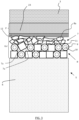
- the second compressible layer 7 When terrain 3 converges, as shown in the picture 3 , the second compressible layer 7 is deformed and allows the ground 3 to move towards the center of the tunnel.
- the ground 3 can break or deform the devices 8, until reaching a state of equilibrium in which the ground 3 is at an equilibrium distance Ge from the external surface of the first layer 6.
- the equilibrium distance Ge is less than the initial distance Gi.
- the breaking strength of the devices 8 is lower than the convergence pressure of the terrain so as to allow the crushing of the devices 8.
- the reference 8a represents broken devices.
- the devices 8 may comprise, all or some of them, a state in which they are broken. This makes it possible to absorb the displacements of the terrain 3 without damaging the tunnel.
- each device 8 in the form of tube has a height H, an outside diameter d 1 and an inside diameter d 2 .
- the height H is equal to the outside diameter d 1 , in order, in particular, to obtain a second layer 7 having a substantially constant thickness E.
- Device 8 is also coated with an adhesive film 11a which surrounds the outer surface of device 8.
- an adhesive film 11b can be deposited on the internal wall of through-hole 10 without obstructing it. Indeed, it is possible, for example, to pour the devices 8 into mortar and use a sieve to remove the excess mortar.
- a film of mortar 11a coats the external surface of the devices and another film of mortar 11b adheres to the internal wall of the through-hole 10 without obstructing it.
- the through hole 10 of the devices 8 is isolated, and the external surface of the devices 8 is coated with an adhesive layer 11. In this case, as illustrated in picture 2 , the inner wall is not coated with an adhesive layer, which guarantees to obtain a larger empty space within the devices.
- FIG. 6 there is shown another embodiment of a device 8 with a through hole 10 having the shape of a ring.
- the ring may be toric and may have a circular section as illustrated in figure 6 .
- a ring can have a torus diameter d s and an inside diameter d i .
- the adhesive film 11 surrounds the outer surface of the body 9 of the device 8, partly penetrating into the through hole 10, without obstructing it.
- the devices (tubes or rings) arranged within the second layer 7 are all substantially identical in order to obtain a homogeneous second layer 7 . In other words, they cannot nest inside each other.
- the second layer 7 preferably comprises devices 8 having a generally tubular shape because they are easier to produce than devices 8 of generally annular shape.
- devices 8 each comprise a solid body 9 delimiting at least one closed cavity (illustrated later in figures 9 to 11 ).
- the construction element 5 is in one piece and comprises the first concrete layer 6 and the second compressible layer 7 formed by the devices 8.
- the body 9 of the devices 8 delimiting one or more closed cavities, prevents mortar or gravel injected into the free space F from penetrating into these cavities.
- the construction element 5 can, however, comprise devices having a body delimiting one or more closed cavities and a third protective layer 12 to protect the second layer 7 during the movement of the element 5, in order, in particular, to avoid breaking the devices 8 during transport.
- the third protective layer 12 guarantees a tightness to the second layer 7, by preventing the filling product 23 from filling the interstices 7a.
- THE figures 9 to 11 illustrate an embodiment of a device 8 whose body 9 delimits at least one closed cavity 10.
- the device 8 has a solid body 9 made of ceramic. Ceramic is suitable for making these devices 8, because it is malleable before a firing step so as to be able to form the closed cavity 10 within the device 8, and because it becomes solid after firing.
- closed cavity 10 is meant an empty space enclosed inside the device 8.
- the solid body 9 of the device 8 is in particular impermeable to liquids, for example to the mortar in the liquid phase before hardening.
- the body 9 of the device 8 extends along a longitudinal axis A of the device 8 and comprises two closed ends 13, 14. The closed ends 13, 14 can each have a linear shape.
- the ends 13, 14 are mutually parallel.
- the ends 13, 14 may be mutually perpendicular.
- body 9 of device 8 has a cylindrical shape.
- cylinder is meant here a solid bounded by a cylindrical surface generated by a straight line, denoted generator, traversing a closed plane curve, denoted directrix, and two parallel planes intersecting the generatrices.
- the body 9 can have the shape of a tube.
- the device 8 can also comprise several cavities, communicating with each other or not.
- the closed cavities 10 of the devices 8 prevent them from fitting into each other, whatever their size and shape.
- the construction element 5 comprises a second compressible layer 7 which can comprise both devices 8 each provided with a through hole 10, and devices 8 whose solid body 9 delimits at least one closed cavity 10 .
- the solid body 9 of the devices 8 are each provided with a through hole and/or the body of which delimits at least one closed cavity.
- an open and curved parallelepipedal formwork 30 is used, to produce a shape of segment, as illustrated in the figure 12 .
- the formwork is open and not curved to produce tunnel sections of various shapes, for example U-shaped or ovoid.
- liquid concrete 31 is poured into the formwork 30, as illustrated in figure 13 .
- metal bars to the liquid concrete 31 to obtain a first incompressible layer of reinforced concrete.
- a first template 32 is used, which is placed on the surface of the concrete 31 and which is moved along the surface in order to form a curved outer surface.
- the concrete 31 is allowed to set, either completely and in this case the concrete has fully hardened, or partially and in this case the concrete has not completely hardened but has hardened sufficiently on the surface to retain the curvature given by the first template 32. Then the first template 32 is removed, and a first layer 6 is thus obtained, the base and the outer surface of which are curved, as illustrated in the figure 14 .
- the solid bodies 9 of the devices 8 have been coated beforehand with the adhesive film 11.
- formwork elements 33 are fixed on the edges of the formwork 30 to raise the formwork 30 and to be able to form the second layer 7, as illustrated in there figure 15 .
- the coated devices 34 are poured into the formwork 30, and more particularly onto the outer surface of the first layer 6.
- the concrete of the first layer does not has not completely hardened.
- an adhesive layer 11 made of mortar is used which will adhere to the outer surface of the first layer 6 which has not yet completely hardened.
- an adhesive layer 11 made from an adhesive for example an adhesive based on epoxy resin which adheres with a hard concrete surface.
- the adhesive film 11 comprises a mortar
- the devices 34 coated with the mortar are poured onto the first layer 6 before the mortar hardens. Then we allows the mortar to harden to secure the second compressible layer 7 to the first layer 6.
- a second template 35 is used, which is placed and moved on the surface of the coated devices 34 in order to form a curved outer surface on the second layer 7, as shown in the figure 15 .
- the adhesive layer 11 is allowed to adhere so that the devices are linked together and to make the second layer 7 integral with the first layer 6.
- the second template 35 is removed and a prefabricated one-piece element 5 is obtained surrounded by the formwork 30, illustrated at figure 16 .
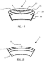
- a third protective layer by pouring mortar 36 on the second layer 7 and moving a third template 37 to curve the outer surface of the third layer.
- the formwork 30 and the formwork elements 33, and if necessary the third template 37 are removed to obtain the one-piece prefabricated construction element 5, as illustrated in figure 18 .
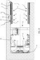
- a tunnel boring machine 15 digs the cavity 2 in the terrain 3 along the direction F1.
- the front of the tunnel boring machine 20 is equipped with means 21 ensuring the cutting of the rock from the terrain 3 and includes means for extracting the rock, not shown for the purposes of simplification.
- a part of the tunnel boring machine 15 ensures the positioning of the construction elements 5 as the tunnel boring machine 15 advances in the direction F1.
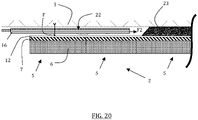
- the tunnel boring machine 15 comprises injection means 22 for injecting a filling product 23, for example mortar or gravel, to fill the free space F delimited between the construction elements 5 and the internal wall of the cavity. 2 formed by the advancement of the tunnel boring machine 15.
- the arrow, indicated by the reference F2 illustrates the path taken by the filling product 23 during its injection.
- the injection of the filling product 23 makes it possible to form a filling layer to occupy the free space F between the construction elements 5 and the terrain 3.
- a free space F delimited between the external wall of the tunnel 1 and the internal wall of the cavity 2 is kept, to place the construction elements in order to form the section 4 of tunnel 1. Then the free space F is filled with the filling product 23.
- the construction element which has just been described makes it possible to facilitate the construction of a tunnel while guaranteeing damping of the convergence of the ground in which the tunnel is located. In addition, it offers better control of the tunnel construction process.
- Such a construction element makes it possible to reduce the thickness of a conventional segment, which greatly reduces the quantity of concrete necessary to make the tunnel.
Landscapes
- Engineering & Computer Science (AREA)
- Architecture (AREA)
- Structural Engineering (AREA)
- Mining & Mineral Resources (AREA)
- Civil Engineering (AREA)
- Life Sciences & Earth Sciences (AREA)
- General Life Sciences & Earth Sciences (AREA)
- Geochemistry & Mineralogy (AREA)
- Geology (AREA)
- Mechanical Engineering (AREA)
- Lining And Supports For Tunnels (AREA)
- Excavating Of Shafts Or Tunnels (AREA)
Claims (13)
- Konstruktionselement zur Herstellung eines Tunnels, umfassend eine inkompressible erste Schicht (6) aus Beton und eine kompressible zweite Schicht (7), die fest mit der ersten Schicht (6) verbunden ist, um ein vorgefertigtes einstückiges Konstruktionselement zu bilden, das dazu konfiguriert ist, in einen Abschnitt des Tunnels integriert zu werden, dadurch gekennzeichnet, dass die zweite Schicht (7) eine Vielzahl von Vorrichtungen (8) umfasst, die jeweils einen festen Körper (9) aufweisen, der einen Hohlraum (10) integriert, und wobei der feste Körper (9) der Vorrichtungen (8) mit einem Klebefilm (11) beschichtet ist, um die Vorrichtungen (8) mit der ersten Schicht (6) zu verbinden.
- Konstruktionselement nach Anspruch 1, wobei die Vorrichtungen (8) jeweils mit einem Durchgangsloch (10) versehen sind.
- Konstruktionselement nach Anspruch 1 oder 2, wobei die Vorrichtungen (8) einen festen Körper (9) aufweisen, der mindestens einen geschlossenen Hohlraum (10) begrenzt.
- Konstruktionselement nach einem der Ansprüche 1 bis 3, wobei der feste Körper (9) der Vorrichtungen (8) aus Keramik hergestellt ist.
- Konstruktionselement nach einem der Ansprüche 1 bis 4, wobei der Klebefilm (11) Mörtel umfasst.
- Konstruktionselement nach einem der Ansprüche 1 bis 5, umfassend eine dritte Schutzschicht (12), die auf der zweiten Schicht (7) angeordnet ist.
- Tunnel in einem Hohlraum (2), der in ein Gelände (3) gegraben ist, wobei mindestens ein Abschnitt des Tunnels aus mindestens einem Konstruktionselement mit zwei Schichten (6, 7) nach einem der Ansprüche 1 bis 5 hergestellt ist.
- Tunnel nach Anspruch 7, wobei jedes Konstruktionselement mit zwei Schichten (6, 7) eine dritte Schutzschicht (12) umfasst, die auf der zweiten Schicht (7) angeordnet ist, und ein Füllstoff einen Freiraum einnimmt, der zwischen der dritten Schutzschicht (12) und dem Gelände (3) begrenzt wird.
- Herstellungsverfahren für ein Konstruktionselement zur Herstellung eines Tunnels, umfassend die folgenden Schritte:- Herstellen einer inkompressiblen ersten Schicht (6) aus Beton; und- Herstellen einer kompressiblen zweiten Schicht (7), die fest mit der ersten Schicht (6) verbunden ist, um ein vorgefertigtes einstückiges Konstruktionselement zu bilden, das dazu konfiguriert ist, in einen Abschnitt des Tunnels integriert zu werden;dadurch gekennzeichnet, dass die zweite Schicht (7) aus einer Vielzahl von Vorrichtungen hergestellt wird, die jeweils einen festen Körper aufweisen, der einen Hohlraum integriert, und dass das Herstellen der zweiten Schicht (7) die folgenden Schritte umfasst:- Beschichten des festen Körpers der Vorrichtungen mit einem Klebefilm (11); und- Schütten der beschichteten Vorrichtungen auf die erste Schicht (6).
- Verfahren nach Anspruch 9, wobei der Körper der Vorrichtungen (8) ein Durchgangsloch (10) aufweist.
- Verfahren nach Anspruch 9 oder 10, wobei die Vorrichtungen (8) einen festen Körper (9) aufweisen, der mindestens einen geschlossenen Hohlraum (10) begrenzt.
- Verfahren nach einem der Ansprüche 9 bis 11, umfassend einen Schutzschritt, in welchem eine dritte Schutzschicht (12) auf der zweiten Schicht (7) angeordnet wird.
- Verfahren zur Herstellung eines Tunnels, umfassend die folgenden Schritte:- Bilden eines Hohlraums in einem Gelände mithilfe einer Tunnelvortriebsmaschine;- Bilden von Abschnitten des Tunnels, die innerhalb des Hohlraums angeordnet sind, wobei im Laufe des Vortriebs der Tunnelvortriebsmaschine mindestens ein Abschnitt aus mindestens einem Konstruktionselement mit zwei Schichten (6, 7) nach einem der Ansprüche 1 bis 6 realisiert wird.
Applications Claiming Priority (2)
| Application Number | Priority Date | Filing Date | Title |
|---|---|---|---|
| FR1401156A FR3021346B1 (fr) | 2014-05-21 | 2014-05-21 | Element de construction pour la realisation d'un tunnel, tunnel comprenant un tel element et procedes de fabrication d'un tel element et d'un tel tunnel |
| PCT/FR2015/051318 WO2015177463A2 (fr) | 2014-05-21 | 2015-05-20 | Élément de construction pour la réalisation d'un tunnel, tunnel comprenant un tel élément et procédés de fabrication d'un tel élément et d'un tel tunnel |
Publications (2)
| Publication Number | Publication Date |
|---|---|
| EP3146155A2 EP3146155A2 (de) | 2017-03-29 |
| EP3146155B1 true EP3146155B1 (de) | 2023-03-08 |
Family
ID=51564700
Family Applications (1)
| Application Number | Title | Priority Date | Filing Date |
|---|---|---|---|
| EP15732774.3A Active EP3146155B1 (de) | 2014-05-21 | 2015-05-20 | Konstruktionselement zur erzeugung eines tunnels, tunnel mit solch einem element und verfahren zur konstruktion solch eines elements und solch eines tunnels |
Country Status (9)
| Country | Link |
|---|---|
| US (1) | US10774640B2 (de) |
| EP (1) | EP3146155B1 (de) |
| JP (3) | JP2017516937A (de) |
| CN (1) | CN106460510B (de) |
| AU (2) | AU2015263203A1 (de) |
| CA (1) | CA2949647C (de) |
| FR (1) | FR3021346B1 (de) |
| RU (1) | RU2689964C2 (de) |
| WO (1) | WO2015177463A2 (de) |
Families Citing this family (9)
| Publication number | Priority date | Publication date | Assignee | Title |
|---|---|---|---|---|
| FR3034451B1 (fr) * | 2015-04-03 | 2017-05-05 | Constructions Mec Consultants | Element de construction pour la realisation d'un tunnel, tunnel comprenant un tel element et procedes de fabrication d'un tel element et d'un tel tunnel |
| US11118988B2 (en) * | 2016-11-12 | 2021-09-14 | Soochow University | Method for calculating earth pressure load on a tunnel |
| USD834218S1 (en) * | 2017-03-20 | 2018-11-20 | Shenzhen Bell Creative Science and Education Co., Ltd. | Component of a construction set |
| FR3091892B1 (fr) * | 2019-01-18 | 2021-01-22 | Agence Nat Pour La Gestion Des Dechets Radioactifs | Ensemble de construction pour la realisation d’un voussoir prefabrique bicouche apte a etre assemble sur site et procede de realisation d’un tel voussoir |
| FR3101650B1 (fr) * | 2019-10-07 | 2021-10-01 | Agence Nat Pour La Gestion Des Dechets Radioactifs Andra | Bloc de construction compressible a vide préfabriqué, pouvant s’integrer dans les revetements de galeries par methodes traditionnelles ou par methode au tunnelier |
| CN111456758B (zh) * | 2020-06-03 | 2021-05-14 | 中国水利水电第十工程局有限公司 | 一种应对岩爆的双护盾tbm管背支护方法 |
| CN113370380A (zh) * | 2021-05-21 | 2021-09-10 | 中交三航局第二工程有限公司 | 一种用于生产悬浮隧道管节的新型预制工艺 |
| CN113565527B (zh) * | 2021-09-27 | 2022-01-04 | 中国科学院地质与地球物理研究所 | 一种适用于活动断裂区和高地应力区的隧道防护结构 |
| CN114165269B (zh) * | 2022-02-14 | 2022-06-17 | 山东建筑大学 | 基于钢混组合支架及喷碹的复合支护系统及其施工工艺 |
Citations (2)
| Publication number | Priority date | Publication date | Assignee | Title |
|---|---|---|---|---|
| DE8716317U1 (de) * | 1987-12-10 | 1989-04-06 | HT Troplast AG, 53840 Troisdorf | Tunnelausbau in Paneelbauweise |
| EP2568113A1 (de) * | 2011-09-12 | 2013-03-13 | Sika Technology AG | Tübbing mit thermoplastischer Schottschicht |
Family Cites Families (24)
| Publication number | Priority date | Publication date | Assignee | Title |
|---|---|---|---|---|
| FR1200989A (fr) | 1958-07-29 | 1959-12-28 | Procédé de revêtement de sol et produits employés pour ce revêtement | |
| BE712437A (de) * | 1967-03-22 | 1968-07-31 | ||
| JPS52292B2 (de) * | 1974-06-20 | 1977-01-06 | ||
| DE2527743C3 (de) * | 1975-06-21 | 1980-04-10 | Wayss & Freytag Ag, 6000 Frankfurt | Tunnelkonstruktion aus Stahlbetontübbings |
| GB2013757B (en) | 1978-02-07 | 1982-06-16 | Mowlem & Co Ltd J | Tunnelling |
| DE3061839D1 (en) * | 1979-02-21 | 1983-03-17 | Mowlem John & Co | Method of constructing a lined tunnel, and lining segment therefor |
| DE3210530C2 (de) * | 1982-03-23 | 1984-01-05 | Bergwerksverband Gmbh, 4300 Essen | Nachgiebiger Betonsegmentausbau |
| JPS5973499U (ja) * | 1982-11-09 | 1984-05-18 | 新日本製鐵株式会社 | 地山押え装置付きセグメント |
| US5439319A (en) * | 1993-08-12 | 1995-08-08 | Carlisle Coatings & Water Proofing, Incorporated | Tunnel barrier system and method of installing the same |
| JP3647111B2 (ja) * | 1995-12-13 | 2005-05-11 | 大日本土木株式会社 | トンネルのライニング構築装置 |
| GB9815685D0 (en) * | 1998-07-20 | 1998-09-16 | Mbt Holding Ag | Waterproofer |
| JP3491671B2 (ja) * | 1998-08-24 | 2004-01-26 | 株式会社大林組 | シールドトンネルの免震構造及びその構築方法並びにそれに用いるシールドトンネル用セグメント |
| JP3760312B2 (ja) * | 2001-04-12 | 2006-03-29 | 清水建設株式会社 | トンネルの構築方法 |
| RU2277147C1 (ru) | 2004-12-15 | 2006-05-27 | Закрытое акционерное общество "Триада-Холдинг" | Способ сооружения обделки тоннеля |
| CN2921279Y (zh) * | 2006-06-03 | 2007-07-11 | 四川省交通厅公路规划勘察设计研究院 | 隧道支护结构 |
| JP4730610B2 (ja) * | 2006-06-20 | 2011-07-20 | 清水建設株式会社 | トンネル掘削工法及びトンネルライナ |
| DE102006055416A1 (de) * | 2006-11-22 | 2008-05-29 | Ed. Züblin Ag | Sicherheitstübbing |
| PL217352B1 (pl) | 2008-02-01 | 2014-07-31 | Alpol Gips Spółka Z Ograniczoną Odpowiedzialnością | Klej, zwłaszcza do kształtek klinkierowych |
| JP4892768B1 (ja) * | 2011-07-28 | 2012-03-07 | 利博 奥村 | シールド型トンネル掘削機及びトンネル掘削方法 |
| EP2834462B1 (de) * | 2012-04-03 | 2018-08-01 | Constructions Mécaniques Consultants | System und verfahren zur abschwächung der konvergenz von gelände und verfahren zur herstellung solch eines systems |
| FR2988770B1 (fr) * | 2012-04-03 | 2014-04-25 | Assistance Et Conseil Ind | Systeme et procede d'amortissement de la convergence d'un terrain |
| CN102996148B (zh) * | 2012-11-22 | 2016-05-04 | 中交第二公路勘察设计研究院有限公司 | 一种高地应力软岩公路隧道支护方法 |
| CN103195086A (zh) * | 2013-04-07 | 2013-07-10 | 中铁二院工程集团有限责任公司 | 一种隧道结构 |
| FR3012513B1 (fr) | 2013-10-31 | 2016-10-14 | Constructions Mec Consultants | Dispositif et systeme d'amortissement de la convergence d'un terrain, procedes de fabrication de tels dispositif et systeme |
-
2014
- 2014-05-21 FR FR1401156A patent/FR3021346B1/fr not_active Expired - Fee Related
-
2015
- 2015-05-20 JP JP2017513357A patent/JP2017516937A/ja active Pending
- 2015-05-20 CN CN201580026159.3A patent/CN106460510B/zh active Active
- 2015-05-20 WO PCT/FR2015/051318 patent/WO2015177463A2/fr not_active Ceased
- 2015-05-20 CA CA2949647A patent/CA2949647C/en active Active
- 2015-05-20 US US15/312,947 patent/US10774640B2/en active Active
- 2015-05-20 EP EP15732774.3A patent/EP3146155B1/de active Active
- 2015-05-20 RU RU2016149893A patent/RU2689964C2/ru not_active Application Discontinuation
- 2015-05-20 AU AU2015263203A patent/AU2015263203A1/en not_active Abandoned
-
2019
- 2019-12-17 AU AU2019283806A patent/AU2019283806B2/en active Active
- 2019-12-20 JP JP2019230834A patent/JP2020056304A/ja active Pending
-
2022
- 2022-05-06 JP JP2022076756A patent/JP7341285B2/ja active Active
Patent Citations (2)
| Publication number | Priority date | Publication date | Assignee | Title |
|---|---|---|---|---|
| DE8716317U1 (de) * | 1987-12-10 | 1989-04-06 | HT Troplast AG, 53840 Troisdorf | Tunnelausbau in Paneelbauweise |
| EP2568113A1 (de) * | 2011-09-12 | 2013-03-13 | Sika Technology AG | Tübbing mit thermoplastischer Schottschicht |
Also Published As
| Publication number | Publication date |
|---|---|
| US10774640B2 (en) | 2020-09-15 |
| JP2022174014A (ja) | 2022-11-22 |
| WO2015177463A2 (fr) | 2015-11-26 |
| CN106460510A (zh) | 2017-02-22 |
| RU2689964C2 (ru) | 2019-05-29 |
| JP2017516937A (ja) | 2017-06-22 |
| JP7341285B2 (ja) | 2023-09-08 |
| EP3146155A2 (de) | 2017-03-29 |
| AU2019283806A1 (en) | 2020-01-16 |
| RU2016149893A3 (de) | 2018-06-26 |
| AU2015263203A1 (en) | 2016-12-15 |
| AU2019283806B2 (en) | 2021-04-01 |
| RU2016149893A (ru) | 2018-06-26 |
| CN106460510B (zh) | 2020-09-15 |
| CA2949647A1 (en) | 2015-11-26 |
| WO2015177463A3 (fr) | 2016-02-04 |
| JP2020056304A (ja) | 2020-04-09 |
| CA2949647C (en) | 2023-01-24 |
| FR3021346A1 (fr) | 2015-11-27 |
| US20170167261A1 (en) | 2017-06-15 |
| FR3021346B1 (fr) | 2016-07-29 |
Similar Documents
| Publication | Publication Date | Title |
|---|---|---|
| EP3146155A2 (de) | Konstruktionselement zur erzeugung eines tunnels, tunnel mit solch einem element und verfahren zur konstruktion solch eines elements und solch eines tunnels | |
| EP2390420B1 (de) | Schlitzwand mit vorgefertigter Hohllamelle und Verfahren zur Herstellung einer solchen Wand | |
| EP0081402B1 (de) | Verfahren zur Herstellung von hohlen Elementen wie etwa Leitungen, Silos oder Bunkern | |
| EP2964837B1 (de) | Verfahren zur herstellung einer schlitzwand und nach diesem verfahren hergestellte schlitzwand | |
| EP0244890B2 (de) | Verfahren zur Herstellung von hohlen Elementen, wie etwa Leitungen, Silos oder Bunker und Elemente, hergestellt durch dieses Verfahren | |
| WO2005064218A1 (fr) | Réalisation, par expansion plastique, d'un assemblage de deux joints tubulaires filetés étanches avec une sous-épaisseur de matière locale et initiale | |
| FR3033514A1 (fr) | Procede de moulage d'elements tubulaires en materiau comportant du ciment et pieu ainsi obtenu | |
| FR2721681A1 (fr) | Procédé de construction de conduites telles que des canalisations de produits pétroliers en mer, tuyaux et dispositifs de raccordement de tuyaux pour la mise en Óoeuvre de ce procédé. | |
| EP3277925B1 (de) | Konstruktionselement zur erzeugung eines tunnels, tunnel mit solch einem element und verfahren zur herstellung solch eines elements und solch eines tunnels | |
| EP3201399B1 (de) | Verfahren zur herstellung eines unterirdischen speicherbehälters und entsprechender behälter | |
| FR3012513A1 (fr) | Dispositif et systeme d'amortissement de la convergence d'un terrain, procedes de fabrication de tels dispositif et systeme | |
| FR2889574A1 (fr) | Structure tubulaire depliable | |
| FR3101650A1 (fr) | Bloc de construction compressible a vide préfabriqué, pouvant s’integrer dans les revetements de galeries par methodes traditionnelles ou par methode au tunnelier | |
| FR2675233A1 (fr) | Element tubulaire prefabrique. | |
| FR3143062A1 (fr) | Étui avec gaine injectable | |
| FR2935996A1 (fr) | Procede de renforcement d'un pont ou viaduc comprenant des voussoirs a caisson | |
| EP1054204A2 (de) | Rohr, insbesondere aus Beton, mit einer Dichtung und ein Verfahren zur Herstellung eines derartigen Rohrs | |
| BE488032A (fr) | Procédé et dispositif de réalisation de constructions creuses precontraintes radialement applicables en particulier aux travaux souterrains | |
| FR3091892A1 (fr) | Ensemble de construction pour la realisation d’un voussoir prefabrique bicouche apte a etre assemble sur site et procede de realisation d’un tel voussoir | |
| BE437110A (de) |
Legal Events
| Date | Code | Title | Description |
|---|---|---|---|
| STAA | Information on the status of an ep patent application or granted ep patent |
Free format text: STATUS: THE INTERNATIONAL PUBLICATION HAS BEEN MADE |
|
| PUAI | Public reference made under article 153(3) epc to a published international application that has entered the european phase |
Free format text: ORIGINAL CODE: 0009012 |
|
| STAA | Information on the status of an ep patent application or granted ep patent |
Free format text: STATUS: REQUEST FOR EXAMINATION WAS MADE |
|
| 17P | Request for examination filed |
Effective date: 20161205 |
|
| AK | Designated contracting states |
Kind code of ref document: A2 Designated state(s): AL AT BE BG CH CY CZ DE DK EE ES FI FR GB GR HR HU IE IS IT LI LT LU LV MC MK MT NL NO PL PT RO RS SE SI SK SM TR |
|
| AX | Request for extension of the european patent |
Extension state: BA ME |
|
| DAV | Request for validation of the european patent (deleted) | ||
| DAX | Request for extension of the european patent (deleted) | ||
| RAP1 | Party data changed (applicant data changed or rights of an application transferred) |
Owner name: AGENCE NATIONALE POUR LA GESTION DES DECHETS RADIO Owner name: CONSTRUCTIONS MECANIQUES CONSULTANTS |
|
| STAA | Information on the status of an ep patent application or granted ep patent |
Free format text: STATUS: EXAMINATION IS IN PROGRESS |
|
| 17Q | First examination report despatched |
Effective date: 20180518 |
|
| GRAP | Despatch of communication of intention to grant a patent |
Free format text: ORIGINAL CODE: EPIDOSNIGR1 |
|
| STAA | Information on the status of an ep patent application or granted ep patent |
Free format text: STATUS: GRANT OF PATENT IS INTENDED |
|
| INTG | Intention to grant announced |
Effective date: 20220530 |
|
| GRAS | Grant fee paid |
Free format text: ORIGINAL CODE: EPIDOSNIGR3 |
|
| GRAJ | Information related to disapproval of communication of intention to grant by the applicant or resumption of examination proceedings by the epo deleted |
Free format text: ORIGINAL CODE: EPIDOSDIGR1 |
|
| GRAL | Information related to payment of fee for publishing/printing deleted |
Free format text: ORIGINAL CODE: EPIDOSDIGR3 |
|
| STAA | Information on the status of an ep patent application or granted ep patent |
Free format text: STATUS: EXAMINATION IS IN PROGRESS |
|
| GRAP | Despatch of communication of intention to grant a patent |
Free format text: ORIGINAL CODE: EPIDOSNIGR1 |
|
| STAA | Information on the status of an ep patent application or granted ep patent |
Free format text: STATUS: GRANT OF PATENT IS INTENDED |
|
| INTC | Intention to grant announced (deleted) | ||
| INTG | Intention to grant announced |
Effective date: 20221013 |
|
| GRAA | (expected) grant |
Free format text: ORIGINAL CODE: 0009210 |
|
| STAA | Information on the status of an ep patent application or granted ep patent |
Free format text: STATUS: THE PATENT HAS BEEN GRANTED |
|
| AK | Designated contracting states |
Kind code of ref document: B1 Designated state(s): AL AT BE BG CH CY CZ DE DK EE ES FI FR GB GR HR HU IE IS IT LI LT LU LV MC MK MT NL NO PL PT RO RS SE SI SK SM TR |
|
| REG | Reference to a national code |
Ref country code: GB Ref legal event code: FG4D Free format text: NOT ENGLISH |
|
| REG | Reference to a national code |
Ref country code: CH Ref legal event code: EP Ref country code: AT Ref legal event code: REF Ref document number: 1552687 Country of ref document: AT Kind code of ref document: T Effective date: 20230315 |
|
| REG | Reference to a national code |
Ref country code: IE Ref legal event code: FG4D Free format text: LANGUAGE OF EP DOCUMENT: FRENCH |
|
| REG | Reference to a national code |
Ref country code: DE Ref legal event code: R096 Ref document number: 602015082728 Country of ref document: DE |
|
| REG | Reference to a national code |
Ref country code: LT Ref legal event code: MG9D |
|
| REG | Reference to a national code |
Ref country code: NL Ref legal event code: MP Effective date: 20230308 |
|
| PG25 | Lapsed in a contracting state [announced via postgrant information from national office to epo] |
Ref country code: RS Free format text: LAPSE BECAUSE OF FAILURE TO SUBMIT A TRANSLATION OF THE DESCRIPTION OR TO PAY THE FEE WITHIN THE PRESCRIBED TIME-LIMIT Effective date: 20230308 Ref country code: NO Free format text: LAPSE BECAUSE OF FAILURE TO SUBMIT A TRANSLATION OF THE DESCRIPTION OR TO PAY THE FEE WITHIN THE PRESCRIBED TIME-LIMIT Effective date: 20230608 Ref country code: LV Free format text: LAPSE BECAUSE OF FAILURE TO SUBMIT A TRANSLATION OF THE DESCRIPTION OR TO PAY THE FEE WITHIN THE PRESCRIBED TIME-LIMIT Effective date: 20230308 Ref country code: LT Free format text: LAPSE BECAUSE OF FAILURE TO SUBMIT A TRANSLATION OF THE DESCRIPTION OR TO PAY THE FEE WITHIN THE PRESCRIBED TIME-LIMIT Effective date: 20230308 Ref country code: HR Free format text: LAPSE BECAUSE OF FAILURE TO SUBMIT A TRANSLATION OF THE DESCRIPTION OR TO PAY THE FEE WITHIN THE PRESCRIBED TIME-LIMIT Effective date: 20230308 Ref country code: ES Free format text: LAPSE BECAUSE OF FAILURE TO SUBMIT A TRANSLATION OF THE DESCRIPTION OR TO PAY THE FEE WITHIN THE PRESCRIBED TIME-LIMIT Effective date: 20230308 |
|
| REG | Reference to a national code |
Ref country code: AT Ref legal event code: MK05 Ref document number: 1552687 Country of ref document: AT Kind code of ref document: T Effective date: 20230308 |
|
| PG25 | Lapsed in a contracting state [announced via postgrant information from national office to epo] |
Ref country code: SE Free format text: LAPSE BECAUSE OF FAILURE TO SUBMIT A TRANSLATION OF THE DESCRIPTION OR TO PAY THE FEE WITHIN THE PRESCRIBED TIME-LIMIT Effective date: 20230308 Ref country code: NL Free format text: LAPSE BECAUSE OF FAILURE TO SUBMIT A TRANSLATION OF THE DESCRIPTION OR TO PAY THE FEE WITHIN THE PRESCRIBED TIME-LIMIT Effective date: 20230308 Ref country code: GR Free format text: LAPSE BECAUSE OF FAILURE TO SUBMIT A TRANSLATION OF THE DESCRIPTION OR TO PAY THE FEE WITHIN THE PRESCRIBED TIME-LIMIT Effective date: 20230609 Ref country code: FI Free format text: LAPSE BECAUSE OF FAILURE TO SUBMIT A TRANSLATION OF THE DESCRIPTION OR TO PAY THE FEE WITHIN THE PRESCRIBED TIME-LIMIT Effective date: 20230308 |
|
| PG25 | Lapsed in a contracting state [announced via postgrant information from national office to epo] |
Ref country code: SM Free format text: LAPSE BECAUSE OF FAILURE TO SUBMIT A TRANSLATION OF THE DESCRIPTION OR TO PAY THE FEE WITHIN THE PRESCRIBED TIME-LIMIT Effective date: 20230308 Ref country code: RO Free format text: LAPSE BECAUSE OF FAILURE TO SUBMIT A TRANSLATION OF THE DESCRIPTION OR TO PAY THE FEE WITHIN THE PRESCRIBED TIME-LIMIT Effective date: 20230308 Ref country code: PT Free format text: LAPSE BECAUSE OF FAILURE TO SUBMIT A TRANSLATION OF THE DESCRIPTION OR TO PAY THE FEE WITHIN THE PRESCRIBED TIME-LIMIT Effective date: 20230710 Ref country code: EE Free format text: LAPSE BECAUSE OF FAILURE TO SUBMIT A TRANSLATION OF THE DESCRIPTION OR TO PAY THE FEE WITHIN THE PRESCRIBED TIME-LIMIT Effective date: 20230308 Ref country code: CZ Free format text: LAPSE BECAUSE OF FAILURE TO SUBMIT A TRANSLATION OF THE DESCRIPTION OR TO PAY THE FEE WITHIN THE PRESCRIBED TIME-LIMIT Effective date: 20230308 Ref country code: AT Free format text: LAPSE BECAUSE OF FAILURE TO SUBMIT A TRANSLATION OF THE DESCRIPTION OR TO PAY THE FEE WITHIN THE PRESCRIBED TIME-LIMIT Effective date: 20230308 |
|
| PG25 | Lapsed in a contracting state [announced via postgrant information from national office to epo] |
Ref country code: SK Free format text: LAPSE BECAUSE OF FAILURE TO SUBMIT A TRANSLATION OF THE DESCRIPTION OR TO PAY THE FEE WITHIN THE PRESCRIBED TIME-LIMIT Effective date: 20230308 Ref country code: PL Free format text: LAPSE BECAUSE OF FAILURE TO SUBMIT A TRANSLATION OF THE DESCRIPTION OR TO PAY THE FEE WITHIN THE PRESCRIBED TIME-LIMIT Effective date: 20230308 Ref country code: IS Free format text: LAPSE BECAUSE OF FAILURE TO SUBMIT A TRANSLATION OF THE DESCRIPTION OR TO PAY THE FEE WITHIN THE PRESCRIBED TIME-LIMIT Effective date: 20230708 |
|
| REG | Reference to a national code |
Ref country code: DE Ref legal event code: R097 Ref document number: 602015082728 Country of ref document: DE |
|
| PLBE | No opposition filed within time limit |
Free format text: ORIGINAL CODE: 0009261 |
|
| STAA | Information on the status of an ep patent application or granted ep patent |
Free format text: STATUS: NO OPPOSITION FILED WITHIN TIME LIMIT |
|
| PG25 | Lapsed in a contracting state [announced via postgrant information from national office to epo] |
Ref country code: MC Free format text: LAPSE BECAUSE OF FAILURE TO SUBMIT A TRANSLATION OF THE DESCRIPTION OR TO PAY THE FEE WITHIN THE PRESCRIBED TIME-LIMIT Effective date: 20230308 |
|
| PG25 | Lapsed in a contracting state [announced via postgrant information from national office to epo] |
Ref country code: SI Free format text: LAPSE BECAUSE OF FAILURE TO SUBMIT A TRANSLATION OF THE DESCRIPTION OR TO PAY THE FEE WITHIN THE PRESCRIBED TIME-LIMIT Effective date: 20230308 Ref country code: MC Free format text: LAPSE BECAUSE OF FAILURE TO SUBMIT A TRANSLATION OF THE DESCRIPTION OR TO PAY THE FEE WITHIN THE PRESCRIBED TIME-LIMIT Effective date: 20230308 Ref country code: LU Free format text: LAPSE BECAUSE OF NON-PAYMENT OF DUE FEES Effective date: 20230520 Ref country code: DK Free format text: LAPSE BECAUSE OF FAILURE TO SUBMIT A TRANSLATION OF THE DESCRIPTION OR TO PAY THE FEE WITHIN THE PRESCRIBED TIME-LIMIT Effective date: 20230308 |
|
| 26N | No opposition filed |
Effective date: 20231211 |
|
| GBPC | Gb: european patent ceased through non-payment of renewal fee |
Effective date: 20230608 |
|
| REG | Reference to a national code |
Ref country code: IE Ref legal event code: MM4A |
|
| PG25 | Lapsed in a contracting state [announced via postgrant information from national office to epo] |
Ref country code: IE Free format text: LAPSE BECAUSE OF NON-PAYMENT OF DUE FEES Effective date: 20230520 |
|
| PG25 | Lapsed in a contracting state [announced via postgrant information from national office to epo] |
Ref country code: IE Free format text: LAPSE BECAUSE OF NON-PAYMENT OF DUE FEES Effective date: 20230520 Ref country code: GB Free format text: LAPSE BECAUSE OF NON-PAYMENT OF DUE FEES Effective date: 20230608 |
|
| PG25 | Lapsed in a contracting state [announced via postgrant information from national office to epo] |
Ref country code: BG Free format text: LAPSE BECAUSE OF FAILURE TO SUBMIT A TRANSLATION OF THE DESCRIPTION OR TO PAY THE FEE WITHIN THE PRESCRIBED TIME-LIMIT Effective date: 20230308 |
|
| PG25 | Lapsed in a contracting state [announced via postgrant information from national office to epo] |
Ref country code: BG Free format text: LAPSE BECAUSE OF FAILURE TO SUBMIT A TRANSLATION OF THE DESCRIPTION OR TO PAY THE FEE WITHIN THE PRESCRIBED TIME-LIMIT Effective date: 20230308 |
|
| PGFP | Annual fee paid to national office [announced via postgrant information from national office to epo] |
Ref country code: DE Payment date: 20250528 Year of fee payment: 11 |
|
| PGFP | Annual fee paid to national office [announced via postgrant information from national office to epo] |
Ref country code: IT Payment date: 20250422 Year of fee payment: 11 Ref country code: BE Payment date: 20250528 Year of fee payment: 11 |
|
| PGFP | Annual fee paid to national office [announced via postgrant information from national office to epo] |
Ref country code: FR Payment date: 20250527 Year of fee payment: 11 |
|
| PGFP | Annual fee paid to national office [announced via postgrant information from national office to epo] |
Ref country code: CH Payment date: 20250603 Year of fee payment: 11 |
|
| PG25 | Lapsed in a contracting state [announced via postgrant information from national office to epo] |
Ref country code: CY Free format text: LAPSE BECAUSE OF FAILURE TO SUBMIT A TRANSLATION OF THE DESCRIPTION OR TO PAY THE FEE WITHIN THE PRESCRIBED TIME-LIMIT; INVALID AB INITIO Effective date: 20150520 |
|
| PG25 | Lapsed in a contracting state [announced via postgrant information from national office to epo] |
Ref country code: HU Free format text: LAPSE BECAUSE OF FAILURE TO SUBMIT A TRANSLATION OF THE DESCRIPTION OR TO PAY THE FEE WITHIN THE PRESCRIBED TIME-LIMIT; INVALID AB INITIO Effective date: 20150520 |
|
| PG25 | Lapsed in a contracting state [announced via postgrant information from national office to epo] |
Ref country code: TR Free format text: LAPSE BECAUSE OF FAILURE TO SUBMIT A TRANSLATION OF THE DESCRIPTION OR TO PAY THE FEE WITHIN THE PRESCRIBED TIME-LIMIT Effective date: 20230308 |