EP3146833A1 - Machine agricole - Google Patents
Machine agricole Download PDFInfo
- Publication number
- EP3146833A1 EP3146833A1 EP16176869.2A EP16176869A EP3146833A1 EP 3146833 A1 EP3146833 A1 EP 3146833A1 EP 16176869 A EP16176869 A EP 16176869A EP 3146833 A1 EP3146833 A1 EP 3146833A1
- Authority
- EP
- European Patent Office
- Prior art keywords
- belt
- drive
- machine control
- work machine
- machine
- Prior art date
- Legal status (The legal status is an assumption and is not a legal conclusion. Google has not performed a legal analysis and makes no representation as to the accuracy of the status listed.)
- Granted
Links
Images

Classifications
-
- A—HUMAN NECESSITIES
- A01—AGRICULTURE; FORESTRY; ANIMAL HUSBANDRY; HUNTING; TRAPPING; FISHING
- A01D—HARVESTING; MOWING
- A01D69/00—Driving mechanisms or parts thereof for harvesters or mowers
- A01D69/06—Gearings
-
- A—HUMAN NECESSITIES
- A01—AGRICULTURE; FORESTRY; ANIMAL HUSBANDRY; HUNTING; TRAPPING; FISHING
- A01D—HARVESTING; MOWING
- A01D41/00—Combines, i.e. harvesters or mowers combined with threshing devices
- A01D41/12—Details of combines
- A01D41/127—Control or measuring arrangements specially adapted for combines
- A01D41/1274—Control or measuring arrangements specially adapted for combines for drives
-
- A—HUMAN NECESSITIES
- A01—AGRICULTURE; FORESTRY; ANIMAL HUSBANDRY; HUNTING; TRAPPING; FISHING
- A01D—HARVESTING; MOWING
- A01D43/00—Mowers combined with apparatus performing additional operations while mowing
- A01D43/08—Mowers combined with apparatus performing additional operations while mowing with means for cutting up the mown crop, e.g. forage harvesters
- A01D43/085—Control or measuring arrangements specially adapted therefor
Definitions
- the present invention relates to an agricultural work machine according to the preamble of claim 1.
- the agricultural work machine in question may be any agricultural work machine equipped with a machine control and at least one belt drive for transmitting drive power.
- These include, for example, tractors, especially tractors, self-propelled harvesters, especially forage harvesters, combine harvester o. The like ..
- this term does not include self-propelled attachments and the combination of the respective tractor with the attachment.
- the agricultural machine ( GB 911,361 A ), from which the invention proceeds, is equipped with a drive arrangement and a plurality of the drive arrangement downstream drive components such as a traction drive, an inclined conveyor or a threshing drum of a combine harvester.
- the drive technology coupling between the drive assembly and the work organs is provided at least partially via belt drives.
- the feeder conveyor is assigned a monitoring device which detects the continuous crop based on the deflection of a carrier of the feederhouse. Based on this acquisition, the machine control activates the travel drive.
- This solution for monitoring the relevant work organ which basically also provides information about the transmitted by means of the belt drive power is structurally complex and tailored to the particular working organ, so that the resulting cost is relatively high.
- the invention is based on the problem to design the known agricultural machine such and further, that their control and / or monitoring is optimized in particular taking into account the transmitted mechanical drive power with simple means.
- Essential is the fundamental consideration that even complex machines with a plurality of belt drives can be controlled and / or monitored in a structurally simple and cost-effective manner by supplying the machine control during operation with a belt extension signal of the relevant drive belt. It has been further recognized that can be concluded from this dynamic belt extension signal, which is due to the load-dependent expansion of the respective drive belt, easily on the output and / or recorded drive power. With a suitable design of the drive belt can be spoken at a constant input speed and neglecting losses such as slippage, friction o. The like. Proportionality between the dynamic belt elongation and the output or recorded drive power, which makes the evaluation very simple.
- the relevant belt drive initially has a belt tensioner which deflects depending on the belt elongation and has a belt expansion sensor.
- the belt expansion sensor determines the deflection of the belt tensioner.
- the machine control then takes over the control and / or monitoring of the working machine during the working operation based on the at least one belt extension signal and a characteristic set associated with the belt drive.
- the characteristic value set takes into account the fact that the mechanical properties of the respective drive belt are different depending on its design, which must be taken into account by the machine control in the control or monitoring of the working machine.
- the dynamic belt elongation signal is in the foreground, which results during the working operation of the working machine.
- the dynamic belt extension signal results from the transmitted via the drive belt driving force, which leads via the modulus of elasticity of the drive belt to a corresponding strain.
- the belt tensioner can be made passive and then is usually spring biased by a spring arrangement on the drive belt.
- the belt tensioner can also be designed actively and, if appropriate in addition to a spring arrangement, act with a drive on the drive belt. In such a case, it must again be taken into consideration that a certain belt elongation can also be due to the drive of the belt tensioner, which can be taken into account, for example, via further correction factors.
- the drive technology coupling between the drive assembly and a working member may be provided via a belt drive or via a plurality of drive technology successively connected belt drives. Furthermore, a plurality of belt drives can branch off from the drive arrangement in parallel drive trains. This shows the scalability of the proposed solution by one and the same measuring principle, namely the determination of the dynamic belt elongation, almost unchanged on different belt drives can be implemented without the measurement arrangement must be changed. This is the subject of the preferred embodiment of claim 2.
- the belt elongation sensor is designed as an angle sensor which is associated with a rocker of the belt tensioner.
- a rocker of the belt tensioner is preferably a tension roller, which rolls on the drive belt.
- Such an angle sensor can be attached in a particularly simple manner to the respective belt tensioner. In particular, a simple retrofitting of existing agricultural machines is possible here.
- the use of the belt extension signal by the machine control can be done in quite different ways. According to claim 5, it may be advantageous to generate from the belt extension signal and the set of characteristic values the transmitted drive power or the transmitted drive power. However, it is also conceivable that only a theoretical comparison value is generated from the belt elongation signal and the characteristic value set, from which the power consumption of the different working organs can be compared.
- the further preferred embodiments according to claims 6 to 8 relate to the calibration of the belt elongation sensors in order to adapt the respective set of characteristic values to the conditions actually prevailing on the working machine. This is primarily about the determination or adaptation of the relationship between the deflection of the belt tensioner and the transmitted drive power and / or the transmitted drive power. On the one hand, the necessity of such a calibration results from the fact that each drive belt has a certain run-in behavior, in which a certain plastic strain sets in. Further plastic strain occurs in a later life cycle phase of the drive belt, which is primarily due to wear of the drive belt.
- the machine control uses the belt extension signal to implement a user selectable operating strategy.
- the operating strategy may be, for example, the requirement to minimize the power consumption of a particular work organ.
- the further preferred embodiments according to claims 11 to 14 relate to the monitoring of the working machine based on the proposed belt extension signal.
- An increase in the machine service life can be increased in the issue of wear information according to claim 11 or a maintenance message according to claim 13 in an uncomplicated manner.
- an emergency function is realized such that the machine control switches off the drive assembly at a maximum expansion, which regularly precedes a rupture of the drive belt.
- the actual rupture of the drive belt which manifests itself in a maximum deflection of the belt tensioner, lead to the shutdown of the drive assembly.
- the term "agricultural work machine” is to be understood comprehensively. In the illustrated embodiment, it is in the proposed agricultural machine 1 to a forage harvester. All versions of the forage harvester apply to all other types of agricultural machinery, especially for a combine harvester, accordingly.
- the agricultural working machine 1 is equipped with a machine control 2, which takes over the control and / or monitoring of the working machine 1.
- the work machine 1 is further equipped with work organs 3-6, which are driven by a drive assembly 7.
- the working machine 1 here initially has a pre-press unit 3, which acts as a feed device for the crop.
- the pre-press unit 3 is provided with two pairs of pre-press rollers 3b-e forming a press channel 3a.
- the front pre-press rolls 3b, 3c take over a pre-compaction of the picked crop, while the rear pre-press rolls 3d, 3e take over a uniform compaction and a further transport of the crop.
- the working machine 1 For chopping the picked crop, the working machine 1 as a further working organ on a chopper 4, to which in turn another working organ a conveyor 5 for the transport of chopped crop in an ejection channel 8 connects.
- the chopper 9 has a knife drum 9a.
- the proposed working machine 1 is further equipped with a traction drive 6 as another working member, which is here and preferably a hydraulic drive.
- the drive assembly 7 is coupled via at least one belt drive 9, 10 with at least one working member 3-6 drive technology.
- the belt drive 9 serves the drive-technical coupling of the drive arrangement 7 with the cutterhead 4a and the conveyor device 5.
- the further belt drive 10, the in Fig. 1 is merely indicated, the drive-technical coupling of the drive assembly 7 is used with the drive 6 or with an associated hydraulic pump system.
- Other belt drives are conceivable here, for example for driving the pre-press unit or the like.
- the belt drive 9 has a drive roller 11, here and preferably a plurality of output rollers 12, 13 and a drive belt 14. In doing so, the in Fig. 1 lower portion of the drive belt 14, the Switzerlandtrum 15 and the upper portion of the drive belt 14 is the Lostrum 16.
- the operating direction of the drive belt 14 is shown in the drawing by arrows.
- the belt drive 9 has a depending on the belt elongation deflecting belt tensioner 17 with a belt strain sensor 18 which determines the deflection of the belt tensioner 17 to generate a belt extension signal 19.
- the further belt drive 10 likewise has a belt tensioner 20 with a corresponding belt elongation sensor 21, which determines the deflection of the belt tensioner 20 in order to generate a belt extension signal 22.
- the machine control 2 activates and / or monitors the working machine 1 during working operation based on the belt extension signal 19 and a characteristic value set assigned to the belt drive 9.
- the belt extension signal 19 are applicable to the belt elongation signal 22.
- the proposed solution can be applied to virtually any working member 3-6 or any group of working members 3-6 driven by a belt drive 9.
- identical belt tensioners 17, 20 with identical belt elongation sensors 18, 21 are used for all belt drives 9, 10, which enables cost-effective control or monitoring of even complex working machines 1.
- the drive arrangement 7 is correspondingly drive-coupled via at least two belt drives 9, 10 with working members 3-6, in that a corresponding belt extension signal 19 can be generated for each belt drive.
- the machine controller 2 is provided with the above-mentioned parameter set, which preferably contains information on the expansion behavior of the relevant drive belt 14, here and preferably an modulus of elasticity (modulus of elasticity) of the relevant drive belt 14, covers.
- the parameter set comprises a relationship between the deflection of the belt tensioner 17 and the drive force transmitted via the drive belt 14.
- the drive force is always accompanied by a corresponding drive torque at the corresponding roller of the belt drive 9, which, however, is dependent on the geometry of the relevant roller, so that in the present case the drive belt 14 always has a corresponding drive torque transmitted driving power is the speech.
- parameter set is to be understood in the present case. In principle, it can also comprise only a single proportionality factor, for example a proportionality factor for the relationship between the deflection of the belt tensioner 17 and the driving force transmitted via the drive belt 14. It is also conceivable that the characteristic value set comprises a plurality of parameters, as explained below.
- the belt tensioner 17 has a deflection component, in this case a rocker 17a, on which a tensioning roller 17b is arranged.
- the tensioning roller 17b is pressed onto the drive belt 14 via a spring arrangement 17c so that the tensioning roller 17b rolls on the drive belt 14.
- the belt expansion sensor 18 is designed as a displacement sensor, here and preferably as an angle sensor, that of the deflection component, here the rocker 17a. associated with the belt tensioner 17.
- the belt elongation sensor 18 is designed as a potentiometer which is coupled to the deflection component, here the rocker 17a, whose deflection is determined.
- the belt tensioner 17 may also be constructed differently than explained above. It is conceivable for example, that the belt tensioner 17 has two or more than two tension rollers 17b, which are hinged to a corresponding adjustment kinematics.
- the machine controller 2 may be advantageous for the machine controller 2 to determine the transmitted drive force from the belt extension signal 19 and the characteristic value set. Alternatively or additionally, it may be advantageous for the machine controller 2 to determine from the belt expansion signal 19 and the belt speed, in particular the rotational speed and the geometry of the drive disk of the belt drive, the respectively transmitted drive power. This takes into account the fact that the transmitted driving force and, at a constant speed of the drive pulley, the transmitted drive power, in a linear relationship to the elongation of the drive belt 14, if it is assumed that the elongation of the drive belt 14 at least over the relevant operating range can be described with a constant modulus of elasticity.
- the machine control 2 preferably regularly, performs a calibration process of the characteristic value set, in particular the relationship between the deflection of the belt tensioner 17 and the transmitted drive force or the transmitted drive power.
- the determination of the characteristic value set or the adaptation of an existing characteristic value set can be provided as part of the calibration process.
- a particularly simple calibration results from the fact that the machine control 2 operates the work machine 1 in the context of the calibration process in a predefined calibration load state of the belt drive 9 and the Characteristic set determined from the determined in the calibration load state belt extension signal 19 or adapted to the determined in the calibration load state belt extension signal 19.
- the calibration load state is preferably defined by the fact that at least one idling working member 3-6 is driven at a predetermined rotational speed or drive power of the drive arrangement 7.
- the drive assembly 7 is operated at maximum speed, while the relevant work organs 3-6 are still idle, so free of crop.
- Such a calibration process can advantageously take place after a turning operation in the headland area of a field, before the work machine 1 enters the field inventory.
- the machine controller 2 is preferably used to set machine parameters of the drive assembly 7 as well as machine parameters of the working members 3-6 in order to implement an operating strategy selected by the user.
- the operating strategy may specifically include the inclusion of drive power by the working members 3-6 and in particular the distribution of the drive power to the working members 3-6.
- at least one selectable operating strategy is preferably stored in the machine controller 2, the machine controller 2 actuating the machine 1, here and preferably the drive arrangement 7 and / or at least one working element 3-6, based on the operating strategy and the at least one belt extension signal 19.
- the operating strategy relates to the drive power generated by the drive assembly 7, here and preferably their distribution to the working members 3-6, wherein the machine control 2 based on the input of the respective working member 3-6 drive power determined the respective belt extension signal 19.
- the operating strategy relates to the adjustment of the machine parameters of the drive arrangement 7 as a function of their output drive power and that the machine control 2 determines the output drive power based on the belt extension signal 19.
- the operating strategy relates to the setting of the machine parameters of at least one working element 3-6 as a function of its recorded drive power, wherein the machine control 2 determines the recorded drive power based on the respective belt extension signal 19.
- the proposed solution can be particularly advantageous in a work machine 1 with multiple belt drives 9, 10 apply. Then it is so that the machine controller 2 from the belt extension signals 19, 22 and the associated sets of characteristic determines the distribution of the drive power of the drive assembly 7 on belt-driven working members 3-6 or groups of belt-driven working members 3-6. In this case, the determination of the above-mentioned, theoretical comparison values may be sufficient, since, for example, a percentage distribution of the drive power to the respective working members 3-6 can already be a sufficient basis for the activation and / or monitoring of the work machine 1.
- the characteristic value set may include information about the influence of the belt wear on the expansion behavior of the drive belt 14, the machine control 2 based on the belt extension signal 19 and the set of characteristic wear information for wear of the drive belt 14 of the respective Belt drive 9 generated.
- a nominal life cycle with at least two life cycle phases is provided for a drive belt 14, which in any case includes a run-in phase and an adjoining operating phase.
- the parameter set comprises information about the expansion behavior of the drive belt 14 in the various life cycle phases, wherein the machine control 2 carries out the control or monitoring of the work machine 1 as a function of the respective current life cycle phase and of the respective characteristic value set.
- the machine controller 2 adjusts by a corresponding adaptation of the characteristic value set that the break-in phase, which regularly lasts about 100 operating hours, requires a retightening of the drive belt 14 and a corresponding calibration process. This can bring the machine control 2 to the operator in good time via the man-machine interface 23, so that the machine service life can be increased as indicated above.
- the characteristic set comprises a Grenzdehn Scheme for the drive belt 14, the machine control 2 can run on reaching the Grenzdehnrios a directed to the belt drive 9 related Grenzdehnroutine.
- the Grenzdehnroutine is preferably a software program that runs in a computing device of the machine control 2.
- the Grenzdehn Scheme can basically be fixed. It is also conceivable that the Grenzdehn Scheme is variable depending on the life cycle phase of the drive belt 14.
- the machine control 2 in the Grenzdehnroutine a maintenance message, here and preferably an indication of the need for a Vietnamesespannens, via the man-machine interface 23 outputs.
- the machine controller 2 in the Grenzdehnroutine the drive assembly 7 and / or the at least one working member 3-6 with limited, in particular reduced, transmitted drive power for the belt drive 9 controls.
- a particularly convenient for the operator variant results from the fact that the machine control 2 based on the belt extension signal 19 and the set of parameters a prognosis on the wear of the drive belt 17, which is preferably output via the man-machine interface 23.
- a prognosis can be generated based on the above-mentioned information about the life cycle of the drive belt 14.
- the characteristic value set comprises a maximum elongation and that the machine control 2 shuts off the drive arrangement 7 when the maximum expansion is reached.
- the machine controller 2 shuts off the drive arrangement 7 upon reaching a maximum deflection of the belt tensioner 17, so that an actual rupture of the drive belt 14 leads to a short-term shutdown of the drive arrangement 7.
- the latter case relates in particular to the situation in which the drive belt 14 jumps from the drive roller 11 and / or the driven roller 12, 13, which can take place, for example, due to the entry of contaminants into the rolling areas of the drive roller 11 or the driven rollers 12, 13.
- the dynamic belt extension signal 19 is subject to constant fluctuations as well as some noise due to the fact that it is picked up during the working operation. Accordingly, it is preferably such that the belt elongation signal 19 is subjected to a filtering, in particular a dynamic averaging, before it is evaluated by the machine control 2, as explained above.
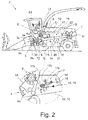
- FIG. 2 shows a proposed working machine 1 in a further embodiment, in which a particularly preferred design variant for the belt tensioner 17 is provided. All versions of the in Fig. 1 shown work machine 1 apply to in Fig. 2 shown work machine 1 accordingly.
- the belt tensioner 17 of Fig. 2 shown working machine 1 shows an above Auslenkkomponente, namely a rocker 17a, which has a different orientation than in Fig. 1 has shown rocker 17a.
- the elongated rocker 17a closes according to FIG Fig. 2 with a portion of extending from the tension roller 17 drive belt 14, here with the in Fig. 2 extending to the right extending section, a shallow angle. This makes it possible to achieve a particularly good clamping effect with good reproducibility of the measurement results.
- Fig. 1 made version for Fig. 2 corresponding.
Landscapes
- Life Sciences & Earth Sciences (AREA)
- Environmental Sciences (AREA)
- Harvester Elements (AREA)
- Devices For Conveying Motion By Means Of Endless Flexible Members (AREA)
Applications Claiming Priority (2)
| Application Number | Priority Date | Filing Date | Title |
|---|---|---|---|
| DE102015116330 | 2015-09-28 | ||
| DE102015121209.9A DE102015121209A1 (de) | 2015-09-28 | 2015-12-07 | Landwirtschaftliche Arbeitsmaschine |
Publications (2)
| Publication Number | Publication Date |
|---|---|
| EP3146833A1 true EP3146833A1 (fr) | 2017-03-29 |
| EP3146833B1 EP3146833B1 (fr) | 2019-06-12 |
Family
ID=56289427
Family Applications (1)
| Application Number | Title | Priority Date | Filing Date |
|---|---|---|---|
| EP16176869.2A Active EP3146833B1 (fr) | 2015-09-28 | 2016-06-29 | Machine agricole |
Country Status (1)
| Country | Link |
|---|---|
| EP (1) | EP3146833B1 (fr) |
Cited By (1)
| Publication number | Priority date | Publication date | Assignee | Title |
|---|---|---|---|---|
| EP4275473A1 (fr) * | 2022-05-09 | 2023-11-15 | Deere & Company | Système de détection de quantité de récolte et procédé pour un ensemble d'entraînement de tondeuse |
Families Citing this family (4)
| Publication number | Priority date | Publication date | Assignee | Title |
|---|---|---|---|---|
| DE102020115974A1 (de) * | 2020-06-17 | 2021-12-23 | Claas Selbstfahrende Erntemaschinen Gmbh | Selbstfahrende Erntemaschine sowie Verfahren zum Betreiben einer selbstfahrenden Erntemaschine |
| DE102021103078A1 (de) | 2021-02-10 | 2022-08-11 | Arburg Gmbh + Co Kg | Vorrichtung und Verfahren zur Überwachung und Einstellung einer Riemenspannung |
| US12259035B2 (en) | 2022-04-14 | 2025-03-25 | Caterpillar Paving Products Inc. | Drive belt wear indication |
| EP4388864A1 (fr) * | 2022-12-20 | 2024-06-26 | McHale Engineering Unlimited Company | Presse à presse et procédé pour déterminer la puissance tractionnée par une chambre à presse à presse et procédé pour déterminer la quantité de matériau dans une chambre à presse à presse et pour déterminer la vitesse au sol optimale pour la presse à presse |
Citations (6)
| Publication number | Priority date | Publication date | Assignee | Title |
|---|---|---|---|---|
| GB911361A (en) | 1958-03-11 | 1962-11-28 | Massey Ferguson Ltd | Improvements in or relating to mobile agricultural crop collecting and treating machines |
| US4130980A (en) * | 1977-01-06 | 1978-12-26 | International Harvester Company | Combine automatic travel control system |
| DD158674A1 (de) | 1981-04-28 | 1983-01-26 | Dietmar Metzner | Vorrichtung zur messung von drehmomenten |
| DE19634619A1 (de) * | 1995-08-28 | 1997-03-06 | Nippon Denso Co | Zubehörteiledrehmoment-Erfassungseinrichtung für ein Riemengetriebe |
| EP1397954A1 (fr) * | 2002-09-13 | 2004-03-17 | Usines Claas France | Machine agricole |
| EP2223588A2 (fr) * | 2009-02-27 | 2010-09-01 | Deere & Company | Récolteuse automobile |
-
2016
- 2016-06-29 EP EP16176869.2A patent/EP3146833B1/fr active Active
Patent Citations (6)
| Publication number | Priority date | Publication date | Assignee | Title |
|---|---|---|---|---|
| GB911361A (en) | 1958-03-11 | 1962-11-28 | Massey Ferguson Ltd | Improvements in or relating to mobile agricultural crop collecting and treating machines |
| US4130980A (en) * | 1977-01-06 | 1978-12-26 | International Harvester Company | Combine automatic travel control system |
| DD158674A1 (de) | 1981-04-28 | 1983-01-26 | Dietmar Metzner | Vorrichtung zur messung von drehmomenten |
| DE19634619A1 (de) * | 1995-08-28 | 1997-03-06 | Nippon Denso Co | Zubehörteiledrehmoment-Erfassungseinrichtung für ein Riemengetriebe |
| EP1397954A1 (fr) * | 2002-09-13 | 2004-03-17 | Usines Claas France | Machine agricole |
| EP2223588A2 (fr) * | 2009-02-27 | 2010-09-01 | Deere & Company | Récolteuse automobile |
Cited By (1)
| Publication number | Priority date | Publication date | Assignee | Title |
|---|---|---|---|---|
| EP4275473A1 (fr) * | 2022-05-09 | 2023-11-15 | Deere & Company | Système de détection de quantité de récolte et procédé pour un ensemble d'entraînement de tondeuse |
Also Published As
| Publication number | Publication date |
|---|---|
| EP3146833B1 (fr) | 2019-06-12 |
Similar Documents
| Publication | Publication Date | Title |
|---|---|---|
| EP3146833B1 (fr) | Machine agricole | |
| DE3048255C2 (de) | Antriebsvorrichtung für eine landwirtschaftlich genutzte Maschine, insbesondere Mähdrescher | |
| DE19903471C1 (de) | Erntemaschine mit Durchsatzmeßvorrichtung | |
| DE102018107804A1 (de) | Höhensteuerungssystem für ein Erntevorsatzgerät | |
| EP2936969A1 (fr) | Combinaison d'un véhicule de traction et d'une moissonneuse tirée par celui-ci | |
| EP2248411B1 (fr) | Moissonneuse | |
| BE1026188B1 (de) | Feldhäcksler mit schnittlängenabhängiger Drehzahl der Konditioniereinrichtung | |
| EP1847169A1 (fr) | Procédé et dispositif destinés au réglage de la longueur de coupe d'un dispositif de fourrage d'une moissonneuse agricole | |
| DE102012212846A1 (de) | Ballenpresse | |
| EP3266299B1 (fr) | Presse à balles | |
| EP2636297B1 (fr) | Moissonneuse automobile | |
| EP1790210B1 (fr) | Dispositif d'alimentation pour une faucheuse-hâcheuse | |
| EP2952087A1 (fr) | Système d'entraînement d'une moissonneuse automotrice | |
| EP3443833A1 (fr) | Chaîne cinématique destinée à l'entraînement d'une unité de travail d'une moissonneuse automotrice | |
| DE102016117867A1 (de) | Ballenpresse | |
| EP2218320B1 (fr) | Ramasseuse-hacheuse dotée d'un dispositif de traitement et de transport de marchandises à réglage couplé | |
| DE102004056233A1 (de) | Landwirtschaftliche Arbeitsmaschine mit einem Antriebsmotor | |
| BE1029376A1 (de) | Antriebsanordnung einer Konditioniereinrichtung eines Feldhäckslers mit einem elektrischen Antriebsstrang | |
| EP3721700B1 (fr) | Dispositif d'enroulement de balles pour une presse à balles rondes et presse à balles rondes | |
| EP3106024A1 (fr) | Presse à balles rondes avec des moyens pour le guidage d'une courroie de presse | |
| DE102015121209A1 (de) | Landwirtschaftliche Arbeitsmaschine | |
| EP3925428A1 (fr) | Machine de récolte autonome, ainsi que procédé de fonctionnement d'une machine de récolte autonome | |
| EP1525787B1 (fr) | Méthode et dispositif pour la régulation de la vitesse d'un moteur dans une machine de travail agricole | |
| EP2108248B1 (fr) | Ramasseuse-hacheuse et dispositif d'introduction pour une ramasseuse-hacheuse | |
| DE10242426A1 (de) | Verfahren zur Steuerung einer Überladeeinrichtung |
Legal Events
| Date | Code | Title | Description |
|---|---|---|---|
| PUAI | Public reference made under article 153(3) epc to a published international application that has entered the european phase |
Free format text: ORIGINAL CODE: 0009012 |
|
| STAA | Information on the status of an ep patent application or granted ep patent |
Free format text: STATUS: THE APPLICATION HAS BEEN PUBLISHED |
|
| AK | Designated contracting states |
Kind code of ref document: A1 Designated state(s): AL AT BE BG CH CY CZ DE DK EE ES FI FR GB GR HR HU IE IS IT LI LT LU LV MC MK MT NL NO PL PT RO RS SE SI SK SM TR |
|
| AX | Request for extension of the european patent |
Extension state: BA ME |
|
| STAA | Information on the status of an ep patent application or granted ep patent |
Free format text: STATUS: REQUEST FOR EXAMINATION WAS MADE |
|
| 17P | Request for examination filed |
Effective date: 20170929 |
|
| RBV | Designated contracting states (corrected) |
Designated state(s): AL AT BE BG CH CY CZ DE DK EE ES FI FR GB GR HR HU IE IS IT LI LT LU LV MC MK MT NL NO PL PT RO RS SE SI SK SM TR |
|
| STAA | Information on the status of an ep patent application or granted ep patent |
Free format text: STATUS: EXAMINATION IS IN PROGRESS |
|
| 17Q | First examination report despatched |
Effective date: 20180503 |
|
| GRAP | Despatch of communication of intention to grant a patent |
Free format text: ORIGINAL CODE: EPIDOSNIGR1 |
|
| STAA | Information on the status of an ep patent application or granted ep patent |
Free format text: STATUS: GRANT OF PATENT IS INTENDED |
|
| INTG | Intention to grant announced |
Effective date: 20190226 |
|
| GRAS | Grant fee paid |
Free format text: ORIGINAL CODE: EPIDOSNIGR3 |
|
| GRAA | (expected) grant |
Free format text: ORIGINAL CODE: 0009210 |
|
| STAA | Information on the status of an ep patent application or granted ep patent |
Free format text: STATUS: THE PATENT HAS BEEN GRANTED |
|
| AK | Designated contracting states |
Kind code of ref document: B1 Designated state(s): AL AT BE BG CH CY CZ DE DK EE ES FI FR GB GR HR HU IE IS IT LI LT LU LV MC MK MT NL NO PL PT RO RS SE SI SK SM TR |
|
| REG | Reference to a national code |
Ref country code: GB Ref legal event code: FG4D Free format text: NOT ENGLISH |
|
| REG | Reference to a national code |
Ref country code: CH Ref legal event code: EP |
|
| REG | Reference to a national code |
Ref country code: AT Ref legal event code: REF Ref document number: 1141333 Country of ref document: AT Kind code of ref document: T Effective date: 20190615 |
|
| REG | Reference to a national code |
Ref country code: DE Ref legal event code: R096 Ref document number: 502016004985 Country of ref document: DE |
|
| REG | Reference to a national code |
Ref country code: IE Ref legal event code: FG4D Free format text: LANGUAGE OF EP DOCUMENT: GERMAN |
|
| REG | Reference to a national code |
Ref country code: NL Ref legal event code: MP Effective date: 20190612 |
|
| REG | Reference to a national code |
Ref country code: LT Ref legal event code: MG4D |
|
| PG25 | Lapsed in a contracting state [announced via postgrant information from national office to epo] |
Ref country code: SE Free format text: LAPSE BECAUSE OF FAILURE TO SUBMIT A TRANSLATION OF THE DESCRIPTION OR TO PAY THE FEE WITHIN THE PRESCRIBED TIME-LIMIT Effective date: 20190612 Ref country code: LT Free format text: LAPSE BECAUSE OF FAILURE TO SUBMIT A TRANSLATION OF THE DESCRIPTION OR TO PAY THE FEE WITHIN THE PRESCRIBED TIME-LIMIT Effective date: 20190612 Ref country code: HR Free format text: LAPSE BECAUSE OF FAILURE TO SUBMIT A TRANSLATION OF THE DESCRIPTION OR TO PAY THE FEE WITHIN THE PRESCRIBED TIME-LIMIT Effective date: 20190612 Ref country code: NO Free format text: LAPSE BECAUSE OF FAILURE TO SUBMIT A TRANSLATION OF THE DESCRIPTION OR TO PAY THE FEE WITHIN THE PRESCRIBED TIME-LIMIT Effective date: 20190912 Ref country code: AL Free format text: LAPSE BECAUSE OF FAILURE TO SUBMIT A TRANSLATION OF THE DESCRIPTION OR TO PAY THE FEE WITHIN THE PRESCRIBED TIME-LIMIT Effective date: 20190612 Ref country code: FI Free format text: LAPSE BECAUSE OF FAILURE TO SUBMIT A TRANSLATION OF THE DESCRIPTION OR TO PAY THE FEE WITHIN THE PRESCRIBED TIME-LIMIT Effective date: 20190612 |
|
| PG25 | Lapsed in a contracting state [announced via postgrant information from national office to epo] |
Ref country code: RS Free format text: LAPSE BECAUSE OF FAILURE TO SUBMIT A TRANSLATION OF THE DESCRIPTION OR TO PAY THE FEE WITHIN THE PRESCRIBED TIME-LIMIT Effective date: 20190612 Ref country code: BG Free format text: LAPSE BECAUSE OF FAILURE TO SUBMIT A TRANSLATION OF THE DESCRIPTION OR TO PAY THE FEE WITHIN THE PRESCRIBED TIME-LIMIT Effective date: 20190912 Ref country code: LV Free format text: LAPSE BECAUSE OF FAILURE TO SUBMIT A TRANSLATION OF THE DESCRIPTION OR TO PAY THE FEE WITHIN THE PRESCRIBED TIME-LIMIT Effective date: 20190612 Ref country code: GR Free format text: LAPSE BECAUSE OF FAILURE TO SUBMIT A TRANSLATION OF THE DESCRIPTION OR TO PAY THE FEE WITHIN THE PRESCRIBED TIME-LIMIT Effective date: 20190913 |
|
| PG25 | Lapsed in a contracting state [announced via postgrant information from national office to epo] |
Ref country code: NL Free format text: LAPSE BECAUSE OF FAILURE TO SUBMIT A TRANSLATION OF THE DESCRIPTION OR TO PAY THE FEE WITHIN THE PRESCRIBED TIME-LIMIT Effective date: 20190612 Ref country code: PT Free format text: LAPSE BECAUSE OF FAILURE TO SUBMIT A TRANSLATION OF THE DESCRIPTION OR TO PAY THE FEE WITHIN THE PRESCRIBED TIME-LIMIT Effective date: 20191014 Ref country code: RO Free format text: LAPSE BECAUSE OF FAILURE TO SUBMIT A TRANSLATION OF THE DESCRIPTION OR TO PAY THE FEE WITHIN THE PRESCRIBED TIME-LIMIT Effective date: 20190612 Ref country code: SK Free format text: LAPSE BECAUSE OF FAILURE TO SUBMIT A TRANSLATION OF THE DESCRIPTION OR TO PAY THE FEE WITHIN THE PRESCRIBED TIME-LIMIT Effective date: 20190612 Ref country code: CZ Free format text: LAPSE BECAUSE OF FAILURE TO SUBMIT A TRANSLATION OF THE DESCRIPTION OR TO PAY THE FEE WITHIN THE PRESCRIBED TIME-LIMIT Effective date: 20190612 Ref country code: EE Free format text: LAPSE BECAUSE OF FAILURE TO SUBMIT A TRANSLATION OF THE DESCRIPTION OR TO PAY THE FEE WITHIN THE PRESCRIBED TIME-LIMIT Effective date: 20190612 |
|
| REG | Reference to a national code |
Ref country code: CH Ref legal event code: PL |
|
| PG25 | Lapsed in a contracting state [announced via postgrant information from national office to epo] |
Ref country code: IS Free format text: LAPSE BECAUSE OF FAILURE TO SUBMIT A TRANSLATION OF THE DESCRIPTION OR TO PAY THE FEE WITHIN THE PRESCRIBED TIME-LIMIT Effective date: 20191012 Ref country code: ES Free format text: LAPSE BECAUSE OF FAILURE TO SUBMIT A TRANSLATION OF THE DESCRIPTION OR TO PAY THE FEE WITHIN THE PRESCRIBED TIME-LIMIT Effective date: 20190612 Ref country code: IT Free format text: LAPSE BECAUSE OF FAILURE TO SUBMIT A TRANSLATION OF THE DESCRIPTION OR TO PAY THE FEE WITHIN THE PRESCRIBED TIME-LIMIT Effective date: 20190612 Ref country code: SM Free format text: LAPSE BECAUSE OF FAILURE TO SUBMIT A TRANSLATION OF THE DESCRIPTION OR TO PAY THE FEE WITHIN THE PRESCRIBED TIME-LIMIT Effective date: 20190612 |
|
| REG | Reference to a national code |
Ref country code: DE Ref legal event code: R097 Ref document number: 502016004985 Country of ref document: DE |
|
| PG25 | Lapsed in a contracting state [announced via postgrant information from national office to epo] |
Ref country code: TR Free format text: LAPSE BECAUSE OF FAILURE TO SUBMIT A TRANSLATION OF THE DESCRIPTION OR TO PAY THE FEE WITHIN THE PRESCRIBED TIME-LIMIT Effective date: 20190612 Ref country code: MC Free format text: LAPSE BECAUSE OF FAILURE TO SUBMIT A TRANSLATION OF THE DESCRIPTION OR TO PAY THE FEE WITHIN THE PRESCRIBED TIME-LIMIT Effective date: 20190612 |
|
| PLBE | No opposition filed within time limit |
Free format text: ORIGINAL CODE: 0009261 |
|
| STAA | Information on the status of an ep patent application or granted ep patent |
Free format text: STATUS: NO OPPOSITION FILED WITHIN TIME LIMIT |
|
| PG25 | Lapsed in a contracting state [announced via postgrant information from national office to epo] |
Ref country code: PL Free format text: LAPSE BECAUSE OF FAILURE TO SUBMIT A TRANSLATION OF THE DESCRIPTION OR TO PAY THE FEE WITHIN THE PRESCRIBED TIME-LIMIT Effective date: 20190612 Ref country code: IE Free format text: LAPSE BECAUSE OF NON-PAYMENT OF DUE FEES Effective date: 20190629 Ref country code: DK Free format text: LAPSE BECAUSE OF FAILURE TO SUBMIT A TRANSLATION OF THE DESCRIPTION OR TO PAY THE FEE WITHIN THE PRESCRIBED TIME-LIMIT Effective date: 20190612 |
|
| 26N | No opposition filed |
Effective date: 20200313 |
|
| PG25 | Lapsed in a contracting state [announced via postgrant information from national office to epo] |
Ref country code: LU Free format text: LAPSE BECAUSE OF NON-PAYMENT OF DUE FEES Effective date: 20190629 Ref country code: CH Free format text: LAPSE BECAUSE OF NON-PAYMENT OF DUE FEES Effective date: 20190630 Ref country code: LI Free format text: LAPSE BECAUSE OF NON-PAYMENT OF DUE FEES Effective date: 20190630 Ref country code: IS Free format text: LAPSE BECAUSE OF FAILURE TO SUBMIT A TRANSLATION OF THE DESCRIPTION OR TO PAY THE FEE WITHIN THE PRESCRIBED TIME-LIMIT Effective date: 20200224 Ref country code: SI Free format text: LAPSE BECAUSE OF FAILURE TO SUBMIT A TRANSLATION OF THE DESCRIPTION OR TO PAY THE FEE WITHIN THE PRESCRIBED TIME-LIMIT Effective date: 20190612 |
|
| PG2D | Information on lapse in contracting state deleted |
Ref country code: IS |
|
| PG25 | Lapsed in a contracting state [announced via postgrant information from national office to epo] |
Ref country code: FR Free format text: LAPSE BECAUSE OF NON-PAYMENT OF DUE FEES Effective date: 20190812 |
|
| GBPC | Gb: european patent ceased through non-payment of renewal fee |
Effective date: 20200629 |
|
| PG25 | Lapsed in a contracting state [announced via postgrant information from national office to epo] |
Ref country code: GB Free format text: LAPSE BECAUSE OF NON-PAYMENT OF DUE FEES Effective date: 20200629 |
|
| PG25 | Lapsed in a contracting state [announced via postgrant information from national office to epo] |
Ref country code: CY Free format text: LAPSE BECAUSE OF FAILURE TO SUBMIT A TRANSLATION OF THE DESCRIPTION OR TO PAY THE FEE WITHIN THE PRESCRIBED TIME-LIMIT Effective date: 20190612 |
|
| PG25 | Lapsed in a contracting state [announced via postgrant information from national office to epo] |
Ref country code: HU Free format text: LAPSE BECAUSE OF FAILURE TO SUBMIT A TRANSLATION OF THE DESCRIPTION OR TO PAY THE FEE WITHIN THE PRESCRIBED TIME-LIMIT; INVALID AB INITIO Effective date: 20160629 Ref country code: MT Free format text: LAPSE BECAUSE OF FAILURE TO SUBMIT A TRANSLATION OF THE DESCRIPTION OR TO PAY THE FEE WITHIN THE PRESCRIBED TIME-LIMIT Effective date: 20190612 |
|
| PG25 | Lapsed in a contracting state [announced via postgrant information from national office to epo] |
Ref country code: MK Free format text: LAPSE BECAUSE OF FAILURE TO SUBMIT A TRANSLATION OF THE DESCRIPTION OR TO PAY THE FEE WITHIN THE PRESCRIBED TIME-LIMIT Effective date: 20190612 |
|
| REG | Reference to a national code |
Ref country code: AT Ref legal event code: MM01 Ref document number: 1141333 Country of ref document: AT Kind code of ref document: T Effective date: 20210629 |
|
| PG25 | Lapsed in a contracting state [announced via postgrant information from national office to epo] |
Ref country code: AT Free format text: LAPSE BECAUSE OF NON-PAYMENT OF DUE FEES Effective date: 20210629 |
|
| P01 | Opt-out of the competence of the unified patent court (upc) registered |
Effective date: 20230516 |
|
| PGFP | Annual fee paid to national office [announced via postgrant information from national office to epo] |
Ref country code: DE Payment date: 20250618 Year of fee payment: 10 |
|
| PGFP | Annual fee paid to national office [announced via postgrant information from national office to epo] |
Ref country code: BE Payment date: 20250618 Year of fee payment: 10 |