EP3148734B1 - Outil portatif - Google Patents
Outil portatif Download PDFInfo
- Publication number
- EP3148734B1 EP3148734B1 EP15722936.0A EP15722936A EP3148734B1 EP 3148734 B1 EP3148734 B1 EP 3148734B1 EP 15722936 A EP15722936 A EP 15722936A EP 3148734 B1 EP3148734 B1 EP 3148734B1
- Authority
- EP
- European Patent Office
- Prior art keywords
- pulley
- working implement
- drive
- belt
- implement according
- Prior art date
- Legal status (The legal status is an assumption and is not a legal conclusion. Google has not performed a legal analysis and makes no representation as to the accuracy of the status listed.)
- Active
Links
Images



Classifications
-
- B—PERFORMING OPERATIONS; TRANSPORTING
- B23—MACHINE TOOLS; METAL-WORKING NOT OTHERWISE PROVIDED FOR
- B23D—PLANING; SLOTTING; SHEARING; BROACHING; SAWING; FILING; SCRAPING; LIKE OPERATIONS FOR WORKING METAL BY REMOVING MATERIAL, NOT OTHERWISE PROVIDED FOR
- B23D59/00—Accessories specially designed for sawing machines or sawing devices
-
- B—PERFORMING OPERATIONS; TRANSPORTING
- B23—MACHINE TOOLS; METAL-WORKING NOT OTHERWISE PROVIDED FOR
- B23D—PLANING; SLOTTING; SHEARING; BROACHING; SAWING; FILING; SCRAPING; LIKE OPERATIONS FOR WORKING METAL BY REMOVING MATERIAL, NOT OTHERWISE PROVIDED FOR
- B23D47/00—Sawing machines or sawing devices working with circular saw blades, characterised only by constructional features of particular parts
- B23D47/12—Sawing machines or sawing devices working with circular saw blades, characterised only by constructional features of particular parts of drives for circular saw blades
-
- B—PERFORMING OPERATIONS; TRANSPORTING
- B23—MACHINE TOOLS; METAL-WORKING NOT OTHERWISE PROVIDED FOR
- B23D—PLANING; SLOTTING; SHEARING; BROACHING; SAWING; FILING; SCRAPING; LIKE OPERATIONS FOR WORKING METAL BY REMOVING MATERIAL, NOT OTHERWISE PROVIDED FOR
- B23D45/00—Sawing machines or sawing devices with circular saw blades or with friction saw discs
- B23D45/16—Hand-held sawing devices with circular saw blades
-
- B—PERFORMING OPERATIONS; TRANSPORTING
- B23—MACHINE TOOLS; METAL-WORKING NOT OTHERWISE PROVIDED FOR
- B23D—PLANING; SLOTTING; SHEARING; BROACHING; SAWING; FILING; SCRAPING; LIKE OPERATIONS FOR WORKING METAL BY REMOVING MATERIAL, NOT OTHERWISE PROVIDED FOR
- B23D47/00—Sawing machines or sawing devices working with circular saw blades, characterised only by constructional features of particular parts
-
- B—PERFORMING OPERATIONS; TRANSPORTING
- B23—MACHINE TOOLS; METAL-WORKING NOT OTHERWISE PROVIDED FOR
- B23Q—DETAILS, COMPONENTS, OR ACCESSORIES FOR MACHINE TOOLS, e.g. ARRANGEMENTS FOR COPYING OR CONTROLLING; MACHINE TOOLS IN GENERAL CHARACTERISED BY THE CONSTRUCTION OF PARTICULAR DETAILS OR COMPONENTS; COMBINATIONS OR ASSOCIATIONS OF METAL-WORKING MACHINES, NOT DIRECTED TO A PARTICULAR RESULT
- B23Q11/00—Accessories fitted to machine tools for keeping tools or parts of the machine in good working condition or for cooling work; Safety devices specially combined with or arranged in, or specially adapted for use in connection with, machine tools
-
- B—PERFORMING OPERATIONS; TRANSPORTING
- B24—GRINDING; POLISHING
- B24B—MACHINES, DEVICES, OR PROCESSES FOR GRINDING OR POLISHING; DRESSING OR CONDITIONING OF ABRADING SURFACES; FEEDING OF GRINDING, POLISHING, OR LAPPING AGENTS
- B24B55/00—Safety devices for grinding or polishing machines; Accessories fitted to grinding or polishing machines for keeping tools or parts of the machine in good working condition
- B24B55/06—Dust extraction equipment on grinding or polishing machines
- B24B55/10—Dust extraction equipment on grinding or polishing machines specially designed for portable grinding machines, e.g. hand-guided
-
- B—PERFORMING OPERATIONS; TRANSPORTING
- B26—HAND CUTTING TOOLS; CUTTING; SEVERING
- B26D—CUTTING; DETAILS COMMON TO MACHINES FOR PERFORATING, PUNCHING, CUTTING-OUT, STAMPING-OUT OR SEVERING
- B26D7/00—Details of apparatus for cutting, cutting-out, stamping-out, punching, perforating, or severing by means other than cutting
- B26D7/18—Means for removing cut-out material or waste
-
- B—PERFORMING OPERATIONS; TRANSPORTING
- B27—WORKING OR PRESERVING WOOD OR SIMILAR MATERIAL; NAILING OR STAPLING MACHINES IN GENERAL
- B27B—SAWS FOR WOOD OR SIMILAR MATERIAL; COMPONENTS OR ACCESSORIES THEREFOR
- B27B5/00—Sawing machines working with circular or cylindrical saw blades; Components or equipment therefor
- B27B5/29—Details; Component parts; Accessories
- B27B5/38—Devices for braking the circular saw blade or the saw spindle; Devices for damping vibrations of the circular saw blade, e.g. silencing
-
- B—PERFORMING OPERATIONS; TRANSPORTING
- B27—WORKING OR PRESERVING WOOD OR SIMILAR MATERIAL; NAILING OR STAPLING MACHINES IN GENERAL
- B27B—SAWS FOR WOOD OR SIMILAR MATERIAL; COMPONENTS OR ACCESSORIES THEREFOR
- B27B9/00—Portable power-driven circular saws for manual operation
-
- B—PERFORMING OPERATIONS; TRANSPORTING
- B28—WORKING CEMENT, CLAY, OR STONE
- B28D—WORKING STONE OR STONE-LIKE MATERIALS
- B28D1/00—Working stone or stone-like materials, e.g. brick, concrete or glass, not provided for elsewhere; Machines, devices, tools therefor
- B28D1/02—Working stone or stone-like materials, e.g. brick, concrete or glass, not provided for elsewhere; Machines, devices, tools therefor by sawing
- B28D1/04—Working stone or stone-like materials, e.g. brick, concrete or glass, not provided for elsewhere; Machines, devices, tools therefor by sawing with circular or cylindrical saw-blades or saw-discs
-
- B—PERFORMING OPERATIONS; TRANSPORTING
- B28—WORKING CEMENT, CLAY, OR STONE
- B28D—WORKING STONE OR STONE-LIKE MATERIALS
- B28D7/00—Accessories specially adapted for use with machines or devices of the preceding groups
- B28D7/02—Accessories specially adapted for use with machines or devices of the preceding groups for removing or laying dust, e.g. by spraying liquids; for cooling work
-
- F—MECHANICAL ENGINEERING; LIGHTING; HEATING; WEAPONS; BLASTING
- F16—ENGINEERING ELEMENTS AND UNITS; GENERAL MEASURES FOR PRODUCING AND MAINTAINING EFFECTIVE FUNCTIONING OF MACHINES OR INSTALLATIONS; THERMAL INSULATION IN GENERAL
- F16D—COUPLINGS FOR TRANSMITTING ROTATION; CLUTCHES; BRAKES
- F16D43/00—Automatic clutches
- F16D43/02—Automatic clutches actuated entirely mechanically
- F16D43/04—Automatic clutches actuated entirely mechanically controlled by angular speed
- F16D43/14—Automatic clutches actuated entirely mechanically controlled by angular speed with centrifugal masses actuating the clutching members directly in a direction which has at least a radial component; with centrifugal masses themselves being the clutching members
-
- F—MECHANICAL ENGINEERING; LIGHTING; HEATING; WEAPONS; BLASTING
- F16—ENGINEERING ELEMENTS AND UNITS; GENERAL MEASURES FOR PRODUCING AND MAINTAINING EFFECTIVE FUNCTIONING OF MACHINES OR INSTALLATIONS; THERMAL INSULATION IN GENERAL
- F16H—GEARING
- F16H55/00—Elements with teeth or friction surfaces for conveying motion; Worms, pulleys or sheaves for gearing mechanisms
- F16H55/32—Friction members
- F16H55/36—Pulleys
-
- F—MECHANICAL ENGINEERING; LIGHTING; HEATING; WEAPONS; BLASTING
- F16—ENGINEERING ELEMENTS AND UNITS; GENERAL MEASURES FOR PRODUCING AND MAINTAINING EFFECTIVE FUNCTIONING OF MACHINES OR INSTALLATIONS; THERMAL INSULATION IN GENERAL
- F16H—GEARING
- F16H7/00—Gearings for conveying rotary motion by endless flexible members
- F16H7/02—Gearings for conveying rotary motion by endless flexible members with belts; with V-belts
-
- F—MECHANICAL ENGINEERING; LIGHTING; HEATING; WEAPONS; BLASTING
- F16—ENGINEERING ELEMENTS AND UNITS; GENERAL MEASURES FOR PRODUCING AND MAINTAINING EFFECTIVE FUNCTIONING OF MACHINES OR INSTALLATIONS; THERMAL INSULATION IN GENERAL
- F16H—GEARING
- F16H7/00—Gearings for conveying rotary motion by endless flexible members
- F16H7/08—Means for varying tension of belts, ropes or chains
- F16H7/10—Means for varying tension of belts, ropes or chains by adjusting the axis of a pulley
- F16H7/12—Means for varying tension of belts, ropes or chains by adjusting the axis of a pulley of an idle pulley
- F16H7/1254—Means for varying tension of belts, ropes or chains by adjusting the axis of a pulley of an idle pulley without vibration damping means
- F16H7/1281—Means for varying tension of belts, ropes or chains by adjusting the axis of a pulley of an idle pulley without vibration damping means where the axis of the pulley moves along a substantially circular path
-
- F—MECHANICAL ENGINEERING; LIGHTING; HEATING; WEAPONS; BLASTING
- F16—ENGINEERING ELEMENTS AND UNITS; GENERAL MEASURES FOR PRODUCING AND MAINTAINING EFFECTIVE FUNCTIONING OF MACHINES OR INSTALLATIONS; THERMAL INSULATION IN GENERAL
- F16H—GEARING
- F16H7/00—Gearings for conveying rotary motion by endless flexible members
- F16H7/08—Means for varying tension of belts, ropes or chains
- F16H2007/0802—Actuators for final output members
- F16H2007/0806—Compression coil springs
-
- F—MECHANICAL ENGINEERING; LIGHTING; HEATING; WEAPONS; BLASTING
- F16—ENGINEERING ELEMENTS AND UNITS; GENERAL MEASURES FOR PRODUCING AND MAINTAINING EFFECTIVE FUNCTIONING OF MACHINES OR INSTALLATIONS; THERMAL INSULATION IN GENERAL
- F16H—GEARING
- F16H7/00—Gearings for conveying rotary motion by endless flexible members
- F16H7/08—Means for varying tension of belts, ropes or chains
- F16H2007/0863—Finally actuated members, e.g. constructional details thereof
- F16H2007/0865—Pulleys
-
- F—MECHANICAL ENGINEERING; LIGHTING; HEATING; WEAPONS; BLASTING
- F16—ENGINEERING ELEMENTS AND UNITS; GENERAL MEASURES FOR PRODUCING AND MAINTAINING EFFECTIVE FUNCTIONING OF MACHINES OR INSTALLATIONS; THERMAL INSULATION IN GENERAL
- F16H—GEARING
- F16H7/00—Gearings for conveying rotary motion by endless flexible members
- F16H7/08—Means for varying tension of belts, ropes or chains
- F16H2007/0889—Path of movement of the finally actuated member
- F16H2007/0893—Circular path
Definitions
- the invention relates to a hand-held implement of the type specified in the preamble of claim 1.
- Such a working device is the WO 2014/053469 A1 refer to.
- the invention has for its object to provide a working device of the generic type, which has an improved braking device with a simple structure.
- the belt drive comprises at least one deflection roller.
- a deflection pulley is located on the load side of each drive belt, which acts between the first and the second pulley.
- the pulley ensures that the braking force can be transmitted via the load strand in case of braking and prevents lifting of the load tube from the pulley.
- the braking device can be arranged so that it acts on the driving, first pulley.
- the braking device need not be placed on the pulley to which the tool is connected, but may be located remotely from the tool. This results in a simple structure.
- the Lasttrum in case of braking is the run of each drive belt, on the braking during the Braking force is transmitted from the first pulley to the second pulley.
- the deflection roller is held stationary during operation of the working device. This ensures that the pulley can not be pushed away when braking.
- the deflection roller is held in place by a releasable fixing device.
- the deflection roller is advantageously mounted pivotably and spring-loaded. Characterized in that the deflection roller is held stationary during operation, the spring can be designed so that results in the dissolved belt fixing the desired belt tension.
- the drive belt can thus be easily tensioned by loosening and, after the spring force has acted on the deflection roller and the belt tensioned, re-fixing the fixing device.
- the belt tension is adjustable without consideration of the forces prevailing during the braking process on the deflection roller forces, since the deflection roller is held stationary in case of braking.
- each belt pulley of the belt drive is looped over a wrap angle of more than about 170 ° by a drive belt of the belt drive.
- each pulley of the belt drive is looped over a wrap angle of more than about 180 ° by a drive belt of the belt drive. This results in particular in the case of braking high transferable forces, so that the tool can be braked.
- at least one pulley is looped over a wrap angle of more than 220 ° by a drive belt of the belt drive.
- the belt drive is advantageously constructed in at least two stages.
- the belt drive comprises a first drive belt and a second drive belt, wherein the first drive belt is passed over the first pulley and a third pulley, wherein the third pulley with a fourth Pulley is rotatably connected and wherein the second drive belt is guided over the fourth pulley.
- the diameter of the fourth pulley is advantageously smaller than the diameter of the third pulley.
- the second drive belt is advantageously guided over the second pulley. This results in an at least two-stage belt drive. However, one or more further drive belts may be provided.
- the at least two-stage design of the belt drive Due to the at least two-stage design of the belt drive, a sufficiently large speed reduction can be achieved with a total compact design.
- the reduction of the rotational speed of the tool causes a reduction of the inertial forces on the tool, so that a braking of the tool is made possible via the belt drive.
- Due to the deflection roller the wrap angle on each pulley can be kept relatively large despite the different diameters of the pulleys.
- the at least one deflection roller acts advantageously on the outer side of a drive belt and presses the drive belt inwardly in the direction of the other run of the belt, so that increase the wrap on the drive pulleys due to the deflection of the drive belt to the deflection roller.
- the first belt pulley is preferably driven directly by the drive motor. Accordingly, no further drive belt is arranged between the drive motor and the first pulley. However, between the first pulley and the drive motor other elements such as a clutch may be arranged.
- a simple construction of the braking device results when the braking device comprises a brake band acting on a brake drum, wherein the brake drum is rotatably connected to the first pulley.
- the brake drum is in a particularly advantageous embodiment, the clutch drum of a centrifugal clutch of the working device.
- the braking device has a braking position and a release position.
- the braking device is advantageously held by a holding device in the release position and biased by a release spring in the direction of the braking position.
- a rapid release of the braking device is made possible with low triggering forces.
- the implement has an actuating element, via which the braking device is adjustable from the braking position into the release position.
- the actuator is advantageous to operate by the operator and may for example be an actuating lever or the like.
- the release spring of the braking device is advantageously tensioned.
- the implement has a control device and a sensor, wherein the control device causes a release of the holding device in the presence of at least one of the sensor determined triggering criterion.
- the sensor is preferably a rotation rate sensor which determines the angular velocity of a movement of the working device about an axis parallel to the axis of rotation of the tool.
- a trigger criterion is advantageous to exceed a predetermined angular velocity about this axis. Moves the implement in an inadmissible manner, this movement can be detected by the rotation rate sensor and the braking device can be triggered. In addition to this trigger criterion, additional triggering criteria can be used.
- the braking device is triggered in response to a speed threshold, in particular when falling below a speed threshold.
- the speed of the second pulley is at most 60% of the speed of the first pulley.
- the implement is preferably a power cutter and the tool is a blade.
- the speed of the cutting wheel is in particular less than about 4,000 revolutions per minute.
- the speed of the cutting wheel is less than about 3,000 revolutions per Minute. This results in a comparatively low moment of inertia of the cutting disc during operation, so that over the belt drive a sufficiently large braking force can be transmitted to the cutting disc.
- Fig. 1 shows as an exemplary embodiment of a hand-held implement a cutting grinder 1.
- the power grinder 1 has a housing 2, on which a boom 3 is fixed.
- a tool 4 namely a cutting disc, rotatably mounted.
- the tool 4 is driven to rotate in a direction of rotation 10.
- the tool 4 is covered by a protective cover 5 over part of its circumference, which in the exemplary embodiment is made in one piece with a housing part 39 (FIG. Fig. 3 ) of the boom 3 is formed.
- the protective cover 5 and the housing part 39 of the cantilever 3 may, for example, be made of metal and be manufactured in a casting process.
- the boom 3 comprises a cover 88 which closes the housing part 39.
- an actuating element 9 is arranged, which in the embodiment as Operating lever is formed and used to actuate a braking device described in more detail below.
- a handle 6 is arranged, which is formed in the embodiment as a rear handle and disposed on the side facing away from the tool 4 of the housing 2.
- the boom 3 projects on the side facing away from the handle 6 of the housing 2 forward.
- a throttle lever 11 and a throttle lock 12 are pivotally mounted on the housing 2 .
- a handle tube 7 is also fixed, which engages over the housing 2 on the side facing the tool 4 of the housing 2.
- the power cutter 1 has a starting device 8 for a drive motor 14 (FIG. Fig. 2 ). To actuate the Anwerfvortechnisch 8 Anwerwergriff 13, which protrudes from the housing 2 is used.
- Fig. 2 shows the structure of the drive of the cutting machine 1 closer.
- the drive motor 14 is designed as an internal combustion engine and has a cylinder 16 in which a combustion chamber 19 is formed.
- the drive motor 14 is designed as a single-cylinder engine.
- the combustion chamber 19 is delimited by a piston 18, which via a connecting rod 20 rotatably drives a crankshaft 21 rotatably mounted in a crankcase 17 about an axis of rotation 22.
- a flywheel 15 is fixed, which may be formed as a fan and may serve to promote cooling air.
- a centrifugal clutch 23 is arranged at the flywheel 15 side facing away from the drive motor 14, a centrifugal clutch 23 is arranged.
- the centrifugal clutch 23 includes a clutch drum serving as a brake drum 24 for a brake device 25.
- a brake band 26 is arranged on the outer circumference of the brake drum 24, a brake band 26 is arranged.
- a first pulley 27 of a belt drive 70 ( Fig. 3 ) rotatably connected.
- a first drive belt 31 is held.
- the Anwerfvorides 8 is rotatably connected to the crankshaft 21 and disposed on the centrifugal clutch 23 side facing away from the first pulley 27.
- the drive motor 14 is a two-stroke engine. However, the drive motor 14 may also be a four-stroke engine.
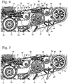
- Fig. 3 shows the structure of the belt drive 70 in detail.
- the belt drive 70 includes the first pulley 27 and a second pulley 28.
- the second pulley 28 is rotatably connected to the tool 4 and rotatably supported about a rotation axis 74.
- the rotation axis 74 is the rotation axis of the tool 4.
- the first drive belt 31 is guided over the first pulley 27 and a third pulley 29.
- the first drive belt 31 forms with the first pulley 27 and the third pulley 29 a first drive stage.
- With the third pulley 29 is a fourth, in Fig. 3 schematically shown pulley 30 rotatably connected.
- a second drive belt 32 is guided.
- the second drive belt 32 forms a second drive stage with the fourth pulley 30 and the second pulley 28.
- On the first drive belt 31 is a first guide roller 35 at.
- the position of the first deflection roller 35 can be fixed via a fixing device 37.
- a deflection roller 36 At the second drive belt 32 is a deflection roller 36, the position of which is also fixable via a fixing device 37.
- an engagement contour 38 for the starting device 8 On the cylinder 16, a spark plug 33 and a decompression valve 34 are arranged.
- the grinder 1 has a rotation rate sensor 40 which is connected to a control device 57.
- the control device 57 is also an electromagnet 44 described in more detail below connected.
- Fig. 4 shows the belt drive 70 in the drive case.
- the brake drum 24 is driven in the direction of the arrow 71 by the drive motor 14.
- the driving force is transmitted to the third pulley 29 via a load strand 62 of the first drive belt 31.
- the other, in Fig. 4 The strand of the drive belt 31 shown above is the empty strand 63 in the drive case.
- the return pulley 35 rests against the slack side 63 in the drive case.
- the second drive belt 32 has a load strand 64, from which the drive force is transmitted from the fourth pulley 30 to the second pulley 28.
- the other, in Fig. 4 Also shown above run of the second drive belt 32 is the slack side 65 on which the deflection roller 36 abuts.
- the first guide roller 35 is mounted on a pivot lever 75 about a pivot axis 77 pivotally mounted on the housing part 39.
- the pivot lever 75 has a groove 79 through which a bolt 96 protrudes, on which a nut 80 is screwed.
- the nut 80 forms with the bolt 96, the fixing device 37 ( Fig. 3 ).
- the second deflection roller 36 is mounted on a corresponding pivot lever 76, which is mounted pivotably about a pivot axis 78 on the housing part 39.
- the pivoting lever 76 likewise has a groove 79, through which a threaded bolt 96 projects, onto which a nut 80 is screwed, and with this the fixing device 37 (FIG. Fig. 3 ) of the deflection roller 36 forms.
- Fig. 5 shows the arrangement in case of braking.
- the load strand 62 of the drive case is the empty strand 67 in the case of braking.
- the empty strand 63 is the load strand 66 against which the deflection roller 35 rests.
- the load strand 64 of the second drive belt 32 in the case of braking is the slack side 69, and the slack side 65 in the drive case is the load run 68 in the case of braking.
- the deflection roller 36 is applied.
- the inertial force of the tool 4 acts in the direction of the arrow 73.
- the arrow 73 points in the direction of rotation 10 of the tool 4 (FIG. Fig. 1 ).
- FIGS. 6 to 9 show the braking device 25 in detail.
- the braking device 25 is shown in its braking position 41. In this position, the brake band 26 ( Fig. 7 ) pulled around the outer circumference of the brake drum 24 and thereby brakes the brake drum 24 and the belt drive 70.
- the braking device 25 has a lever assembly 47, which comprises a lever 48, a release lever 51 and a toggle lever assembly 91.
- the toggle assembly 91 has a first link 49 and a second link 92.
- Fig. 8 shows is the Lever 48 mounted about a pivot axis 53 on the first housing part 39. At a first end 89 of the lever 48, the brake band 26 is held.
- the release lever 51 is an in Fig. 7 shown pivot axis 52 pivotally mounted on the housing part 39 ( Fig. 6 ) held.
- the first pivot lever 49 is pivotally mounted about a pivot axis 54 on the second pivot lever 92.
- the second pivot lever 92 is held with play on the release lever 51 and slightly to compensate for tolerance about the pivot axis 52 of the release lever 51 pivotally.
- the second pivot lever 92 is held between actuation contours 93 and 95 of the release lever 51.
- the second end of the first articulated lever 49 is fixed about a pivot axis 60 pivotally mounted on the lever 48.
- the release lever 51 is a in Fig. 8 shown trigger spring 45 biased toward the braking position 41.
- the release lever 51 has a holding plate 50, which cooperates in the release position 42 of the braking device 25 with an electromagnet 44.
- the electromagnet 44 forms with the holding plate 50, a holding device 43, which the braking device 25 in its release position 42 (FIGS. Fig. 9 ) holds.
- At the release lever 51 also engages in Fig. 6 shown coupling element 55, which is connected to the actuating element 9.
- the coupling element 55 comprises a longitudinal guide 56.
- the release lever 51 is guided with a bearing element 59 in the longitudinal guide 56. If the actuator 9 from the in Fig. 7 shown position in the direction of arrow 94 in the in Fig. 9 shown pivoted position, so the coupling element 55 takes the release lever 51 on the bearing element 59 and pivots it about the pivot axis 52 (FIG. Fig. 7 ).
- the release spring 45 and the brake spring 46 are tensioned.
- the holding plate 50 reaches the electromagnet 44.
- the electromagnet 44 is energized during operation of the cut-off grinder 1 and thereby holds the magnetic holding plate 50.
- the braking device 25 is in its in Fig. 9 shown release position 42 held.
- the power for energizing the electromagnet 44 is generated in operation due to the rotation of the crankshaft 21. If the speed of the drive motor 14 and Thus, the crankshaft 21 below a predetermined design speed, so the energy of the electromagnet 44 is no longer enough to hold the support plate 50.
- the release lever 51 is pivoted by the release spring 45, and the braking device 25 is moved to its braking position 41. When the drive motor 14 is at a standstill, the braking device 25 is thereby in its braking position 41.
- It may be provided to provide further energy storage devices which supply the electromagnet 44 with energy. As a result, the speed, below which the braking device 25 is adjusted in its braking position 41, are shifted to low speeds.
- the additional energy storage devices may be, for example, batteries, capacitors, a mechanical flywheel or the like.
- the release lever 51 pivots when pivoting out of the braking position 41 (FIG. Fig. 8 ) into the release position 42 (FIG. Fig. 9 ) about the pivot axis 52.
- the trigger lever 51 takes the second pivot lever 92 via the actuating contour 93.
- the dead center of the toggle lever assembly 91 is overcome.
- the brake spring 46 is tensioned when pivoting the lever 48 and the brake band 26 is released.
- the power supply to the electromagnet 44 is interrupted or the electromagnet 44 made available energy drops due to falling speed below a structurally specified threshold.
- the holding plate 50 is thus no longer held on the electromagnet 44.
- the release lever 51 Due to the bias of the release spring 45, the release lever 51 is pivoted.
- the trigger lever 51 takes the second pivot lever 92 via the actuating contour 95 and thereby adjusts the toggle lever arrangement 91 via its dead center position into a position in which the brake spring 46 acts on the lever 48. Due to the force of the brake spring 46 pivots the lever 48 and thereby biases the brake band 26. This allows the arrangement with little force in the release position 42 are held, and to trigger the braking operation, only a small force on the trigger lever 51 is required.
- the Release spring 45 only has to pivot the release lever 51 until the dead center of the toggle lever assembly 91 has been overcome. For this purpose, only a small force and a low suspension travel are required.
- a trigger spring 45 may for example also be provided a leg spring. The braking force itself is applied by the preloaded brake spring 46.
- a stop 61 is formed on the housing part 39 for the release lever 51.
- the stop 61 is advantageously formed of an elastic material and serves to cushion the holding plate 50 upon adjustment of the braking device 25 in the braking position 41. It may also be provided alternatively to provide a stop for the release lever 51.
- the stop of elastic material can be provided on the housing part 39 and / or on the release lever 51 or on the holding plate 50.
- the actuating element 9 Due to the decoupling of the position of the actuating element 9 from the position of the bearing element 59 via the longitudinal guide 56, the actuating element 9 can after pivoting in the direction of the arrow 94 in Fig. 7 , So after the adjustment of the braking device 25 from the release position 42 in the braking position 41, are pivoted back. The braking device 25 is thereby of the holding device 43 in the in Fig. 9 shown brake position 41 held.
- the operator adjusts the braking device into the release position 42 before starting work with the cut-off grinder.
- the solenoid 44 is connected via a connecting line 58 to the controller 57, which in accordance with Fig. 3 is also connected to the rotation rate sensor 40.
- the rotation rate sensor 40 determines the angular velocity of a movement of the working device about an axis parallel to the axis of rotation 74 of the tool 4.
- the control device 57 releases the braking device 25 by interrupting the power supply to the electromagnet 44.
- the release spring 45 and the brake spring 46 adjust the brake device 25 with dissolved holding device 43 in the braking position 41 and brake the brake drum 24.
- the tool 4 is braked. If the speed of the drive motor 14 drops below a design-dictated speed threshold, then the energy of the electromagnet 44 is no longer sufficient to hold the brake device 25 in the release position 52, and the brake device 25 is adjusted to its braking position 41.
- the first pulley 27 has a diameter a and is surrounded by the first drive belt 31 over a wrap angle ⁇ , which is advantageously at least about 170 °, in particular more than about 180 °.
- the wrap angle ⁇ is approximately 180 °.
- the third pulley 29 has a diameter b which is significantly larger than the diameter a of the first pulley 27.
- the third pulley 29 is looped over a wrap angle ⁇ from the first drive belt 31, which is advantageously more than about 170 °, in particular more than about 180 °.
- the wrap angle ⁇ is at least about 220 °.
- the fourth pulley 30 has a diameter c which is significantly smaller than the diameter b of the third pulley 29.
- the diameter b may for example be twice, preferably at least 2.5 times the diameter c.
- the fourth pulley 30 is looped by the second drive belt 32 over a wrap angle ⁇ , which is advantageously at least about 170 °, in particular at least about 180 °.
- the second pulley 28 has a diameter d, which may preferably correspond approximately to the diameter b of the third pulley 29.
- the diameter d is significantly larger than the diameter c of the fourth pulley 30.
- the diameter d may for example be at least twice, preferably at least 2.5 times the diameter c.
- the second pulley 28 is looped by the second drive belt 32 over a wrap angle ⁇ , which is advantageously more than about 180 °, in particular at least about 220 °.
- the comparatively large wrap angles ⁇ and ⁇ are achieved due to the deflection rollers 35 and 36. Due to the different diameters of the pulleys 28 to 30 it is achieved that the rotational speed of the second pulley 28 is significantly smaller than the rotational speed of the first pulley 27.
- the speed of the second pulley 28 is at most about 60% of the speed of the first pulley 27.
- the speed of the tool 4, namely the blade of the abrasive cutter 1 is advantageously less than about 4,000 revolutions per minute, preferably less than about 3,000 revolutions per minute. Due to the lower speed of the second pulley 28, the torque transmitted to the second pulley 29 is significantly greater than the torque transmitted by the first pulley 27 to the first drive belt (31).
- a deflection roller 36 on the drive belt 32 is advantageous.
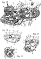
- FIGS. 12 to 15 show the design and storage of the pulleys 35 and 36 in detail.
- the two pivot levers 75 and 76 are advantageously identical.
- a spring 81 Adjacent to each guide roller 35, 36, a spring 81 is mounted on the housing part 39, which is formed in the embodiment as a torsion spring.
- the spring 81 is covered by a retaining plate 82 on its front side and thereby fixed axially.
- the retaining plate 82 is fixed with a fastening screw 83 on the housing part 39.
- the spring 81 has an end 84 which acts on the pivot lever 76.
- Fig. 14 shows, on the pivot lever 76, a pin 85 is held, on which the end 84 of the spring 81 engages.
- the spring 81 is held on a bearing neck 87 of the housing part 39.
- the guide roller 36 is rotatably mounted on a bearing pin 86 on the pivot lever 76.
- the second end of the spring 81 is supported on the housing part 39.
- the Storage of the guide roller 35 on the pivot lever 75 is formed according to the storage of the guide roller 36.
- the braking device 25 acts on the first pulley 27. However, it may also be provided that the braking device 25 acts on the fourth pulley 30. Also, the fourth pulley 30 is a driving pulley. In the arrangement of a braking device 25 on the fourth pulley 30 results in a simple structure, since the braking device 25 does not need to be on the driven pulley 28, so not in the immediate vicinity of the tool 4, to be arranged.
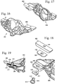
- FIGS. 16 to 18 show an embodiment of a trigger lever 101 for the braking device 25.
- the structure of the trigger lever 101 substantially corresponds to that of the trigger lever 51.
- the trigger lever 101 is pivotally mounted about a pivot axis 52.
- a holding plate 100 is fixed, which is slightly movable to compensate for tolerances relative to the trigger lever 101, in particular tiltable. This can ensure that the holding plate 100 can rest flat on the electromagnet 44, whereby a sufficiently high holding force is ensured.
- the release lever 101 has a mounting portion 102 to which the holding plate 100 is fixed.
- An attachment opening 103 extends through the attachment region 102, through which a fastening screw 104 projects.
- the fastening screw 104 is screwed into the holding plate 100 in the exemplary embodiment.
- the fastening screw 104 has a threaded portion 110, which is screwed into a provided with an internal thread mounting opening 109 of the retaining plate 100.
- a damping element 105 is arranged between the head 111 of the fastening screw 104 and the mounting portion 102.
- the damping element 105 has a fastening opening 107, through which the fastening screw 104 protrudes. Between the fastening region 102 and the retaining plate 100, a further damping element 106 is arranged, which has a fastening opening 108, through which the fastening screw 104 protrudes.
- the damping elements 105 and 106 are made of an elastic material and are formed in the embodiment as a flat plates.
- Fig. 19 shows the construction in assembled condition.
- the damping element 105 is arranged, and on the opposite side of the fastening region 102, the retaining plate 100 is arranged.
- the damping element 106 is arranged between the fastening region 102 and the retaining plate 100 and projects into a recess in the retaining plate 100.
- the arrangement is made such that the retaining plate 100 is slightly movable relative to the fastening region 102 of the triggering lever 101, in particular about its longitudinal axis and about its Transverse axis is tilted. As a result, tolerances between the holding plate 100 and the electromagnet 44 can be compensated, and the holding plate 100 can lie flat against the electromagnet 44.
Landscapes
- Engineering & Computer Science (AREA)
- Mechanical Engineering (AREA)
- Life Sciences & Earth Sciences (AREA)
- General Engineering & Computer Science (AREA)
- Forests & Forestry (AREA)
- Wood Science & Technology (AREA)
- Mining & Mineral Resources (AREA)
- Finish Polishing, Edge Sharpening, And Grinding By Specific Grinding Devices (AREA)
- Harvester Elements (AREA)
- Braking Arrangements (AREA)
- Devices For Conveying Motion By Means Of Endless Flexible Members (AREA)
Claims (18)
- Appareil portatif avec un moteur d'entraînement (14) qui entraine en rotation un outil (4) par l'intermédiaire d'une transmission à courroie (70), la transmission à courroie (70) comportant au moins une première poulie à courroie (27), d'entraînement, au moins une deuxième poulie à courroie (28), entraînée, au moins une courroie d'entraînement (31, 32) agissant entre la première poulie (27) et la deuxième poulie (28), pour transmettre le couple d'entraînement, la deuxième poulie (28) étant reliée, fixe en rotation, à l'outil (4), la vitesse de rotation de la deuxième poulie (28), en fonctionnement, étant inférieure à la vitesse de rotation de la première poulie (27), et l'appareil comportant un dispositif de freinage (25) qui agit sur la première poulie (27),
caractérisé en ce que la transmission à courroie (70) comprend au moins une poulie de renvoi (35, 36), au moins une poulie de renvoi (35, 36) étant appliquée, en cas de freinage, contre le brin de charge (66, 68) de chaque courroie d'entraînement (31, 32) qui agit entre la première poulie à courroie (27) et la deuxième poulie à courroie (28). - Appareil selon la revendication 1,
caractérisé en ce que la poulie de renvoi (35, 36), lors du fonctionnement dudit appareil, est maintenue stationnaire. - Appareil selon la revendication 2,
caractérisé en ce que la poulie de renvoi (35, 36) est maintenue stationnaire par l'intermédiaire d'un dispositif de fixation (37) apte à être desserré, et en ce que ladite poulie de renvoi (35, 36), quand le dispositif de fixation (37) est desserré, est montée pivotante et à ressort. - Appareil selon l'une des revendications 1 à 3,
caractérisé en ce qu'une courroie d'entraînement (31, 32) de la transmission à courroie (70) s'enroule sur chaque poulie à courroie (27, 28, 29, 30) de la transmission à courroie (70) sur un angle d'enroulement (α, β, γ, δ) de plus de 170°, environ. - Appareil selon la revendication 4,
caractérisé en ce qu'une courroie d'entraînement (31, 32) de la transmission à courroie (70) s'enroule sur au moins une poulie (28, 29) sur un angle d'enroulement (β, δ) d'environ 220°. - Appareil selon l'une des revendications 1 à 5,
caractérisé en ce que la transmission à courroie (70) comprend une première courroie d'entraînement (31) et une deuxième courroie d'entraînement (32), la première courroie d'entraînement (31) passant sur la première poulie à courroie (27) et sur une troisième poulie à courroie (29), la troisième poulie à courroie (29) étant reliée fixe en rotation à une quatrième poulie à courroie (30), et la deuxième courroie d'entraînement (32) passant sur la quatrième poulie à courroie (30). - Appareil selon la revendication 6,
caractérisé en ce que le diamètre (c) de la quatrième poulie à courroie (30) est plus petit que le diamètre (b) de la troisième poulie à courroie (29). - Appareil selon la revendication 6 ou 7,
caractérisé en ce que la deuxième courroie d'entraînement (32) passe sur la deuxième poulie à courroie (28). - Appareil selon l'une des revendications 6 à 8,
caractérisé en ce que la première poulie à courroie (27), en fonctionnement, est entraînée par le moteur d'entraînement (14). - Appareil selon l'une des revendications 1 à 9,
caractérisé en ce que le dispositif de freinage (25) comprend une bande de freinage (26) qui agit sur un tambour de frein (24), le tambour de frein (24) étant relié fixe en rotation à la première poulie à courroie (27). - Appareil selon l'une des revendications 1 à 10,
caractérisé en ce que le dispositif de freinage (25) présente une position de freinage (41) et une position de déblocage (42), le dispositif de freinage (25) étant retenu par un dispositif de retenue (43) dans la position de déblocage (42) et étant précontraint par un ressort de déclenchement (45) en direction de la position de freinage (41). - Appareil selon la revendication 11,
caractérisé en ce que ledit appareil comporte un élément d'actionnement (9) par l'intermédiaire duquel le dispositif de freinage (25) est apte à être déplacé de la position de freinage (41) jusqu'à la position de déblocage (42). - Appareil selon l'une des revendications 10 à 12,
caractérisé en ce que le dispositif de retenue (43) comprend un électro-aimant (44). - Appareil selon la revendication 13,
caractérisé en ce que ledit appareil comporte un dispositif de commande (57) et un capteur, et en ce que le dispositif de commande (57), en présence d'au moins un critère de déclenchement déterminé par le capteur, provoque un desserrage du dispositif de retenue (43). - Appareil selon la revendication 14,
caractérisé en ce que le capteur est un capteur de vitesse angulaire (40) qui détermine la vitesse angulaire d'un mouvement de l'appareil sur un axe parallèle à l'axe de rotation (74) de l'outil (4), et en ce qu'un critère de déclenchement est le dépassement d'une vitesse angulaire prédéfinie, sur cet axe. - Appareil selon l'une des revendications 1 à 15,
caractérisé en ce que la vitesse de rotation de la deuxième poulie à courroie (28) représente au maximum 60% de la vitesse de rotation de la première poulie à courroie (27). - Appareil selon l'une des revendications 1 à 16,
caractérisé en ce que ledit appareil est une tronçonneuse à meule (1), et l'outil (4) est une meule à tronçonner. - Appareil selon la revendication 17,
caractérisé en ce que la vitesse de rotation de la meule à tronçonner est inférieure à 4000 t/min.
Applications Claiming Priority (2)
| Application Number | Priority Date | Filing Date | Title |
|---|---|---|---|
| DE102014007878.7A DE102014007878A1 (de) | 2014-05-24 | 2014-05-24 | Handgeführtes Arbeitsgerät |
| PCT/EP2015/001008 WO2015180829A1 (fr) | 2014-05-24 | 2015-05-15 | Outil portatif |
Publications (2)
| Publication Number | Publication Date |
|---|---|
| EP3148734A1 EP3148734A1 (fr) | 2017-04-05 |
| EP3148734B1 true EP3148734B1 (fr) | 2018-10-24 |
Family
ID=53181241
Family Applications (2)
| Application Number | Title | Priority Date | Filing Date |
|---|---|---|---|
| EP15722936.0A Active EP3148734B1 (fr) | 2014-05-24 | 2015-05-15 | Outil portatif |
| EP15727551.2A Active EP3148735B1 (fr) | 2014-05-24 | 2015-05-15 | Outil portatif |
Family Applications After (1)
| Application Number | Title | Priority Date | Filing Date |
|---|---|---|---|
| EP15727551.2A Active EP3148735B1 (fr) | 2014-05-24 | 2015-05-15 | Outil portatif |
Country Status (5)
| Country | Link |
|---|---|
| US (2) | US10610938B2 (fr) |
| EP (2) | EP3148734B1 (fr) |
| CN (3) | CN108788303B (fr) |
| DE (1) | DE102014007878A1 (fr) |
| WO (2) | WO2015180829A1 (fr) |
Families Citing this family (17)
| Publication number | Priority date | Publication date | Assignee | Title |
|---|---|---|---|---|
| DE102014007878A1 (de) | 2014-05-24 | 2015-11-26 | Andreas Stihl Ag & Co. Kg | Handgeführtes Arbeitsgerät |
| US11685034B2 (en) | 2014-05-24 | 2023-06-27 | Andreas Stihl Ag & Co. Kg | Handheld work apparatus |
| DE102016013907A1 (de) * | 2016-11-22 | 2018-05-24 | Andreas Stihl Ag & Co. Kg | Handgeführtes Arbeitsgerät |
| EP3412391B1 (fr) * | 2017-06-09 | 2021-11-17 | Andreas Stihl AG & Co. KG | Engin doté d'un dispositif de freinage électromagnétique |
| DE102017005558A1 (de) | 2017-06-09 | 2018-12-13 | Andreas Stihl Ag & Co. Kg | Verfahren zur Ermittlung des Verschleißzustandes einer Bremseinrichtung in einem handgeführten Arbeitsgerät |
| EP3412392B1 (fr) * | 2017-06-09 | 2021-09-01 | Andreas Stihl AG & Co. KG | Appareil de travail manuel comprenant un outil et un dispositif de frein pour l'outil |
| DE102017008391A1 (de) * | 2017-09-07 | 2019-03-07 | Andreas Stihl Ag & Co. Kg | Arbeitsgerät und Verfahren zu dessen Betrieb |
| SE542372C2 (en) * | 2018-04-04 | 2020-04-21 | Husqvarna Ab | A floor surfacing machine with a tool holder disc comprising a biasing member |
| CN109514743B (zh) * | 2019-01-09 | 2023-10-20 | 泉州市大鲨鱼机械科技有限公司 | 一种绳锯机的飞轮驱动装置 |
| SE543615C2 (en) * | 2019-02-21 | 2021-04-20 | Husqvarna Ab | A handheld cut-off saw for cutting concrete and stone comprising a drive arrangement for driving a circular cutting tool |
| WO2021021534A1 (fr) * | 2019-07-26 | 2021-02-04 | Milwaukee Electric Tool Corporation | Scie circulaire |
| EP3825067A1 (fr) | 2019-11-21 | 2021-05-26 | Hilti Aktiengesellschaft | Procédé de fonctionnement d'une machine-outil et machine-outil |
| SE544811C2 (en) | 2020-10-19 | 2022-11-29 | Husqvarna Ab | A hand-held electrically powered cut-off tool with a kickback mitigation function |
| EP4488006A3 (fr) | 2020-10-19 | 2025-03-26 | Husqvarna AB | Outil de coupure électrique portatif avec fonction d'atténuation de rebond |
| JP1710863S (ja) * | 2021-10-26 | 2022-03-25 | 携帯用電気切断機本体 | |
| JP2024161701A (ja) * | 2023-05-08 | 2024-11-20 | 株式会社やまびこ | 動力切断機 |
| JP2024162028A (ja) * | 2023-05-09 | 2024-11-21 | 株式会社やまびこ | 動力切断機 |
Family Cites Families (56)
| Publication number | Priority date | Publication date | Assignee | Title |
|---|---|---|---|---|
| GB191501284A (en) * | 1914-02-02 | 1916-01-20 | Vulkan Maschinenfabriks Actien | Electric Controlling Apparatus for the Tool Carriers of Metal Working Machines. |
| US2455840A (en) * | 1944-11-03 | 1948-12-07 | Webb James Stewart | Tree-felling saw attachment for tractors |
| US3513888A (en) * | 1967-07-10 | 1970-05-26 | Textron Inc | Portable power driven circular saw |
| US3735489A (en) * | 1971-02-18 | 1973-05-29 | Textron Inc | Hand-held power tool with rotary tool disc at end of reversible forwardly projecting arm |
| US3785230A (en) * | 1972-11-08 | 1974-01-15 | Lokey Tool Inc | Automatic safety brake for rotary blade equipment |
| US4006528A (en) * | 1974-11-22 | 1977-02-08 | Kaaz Machinery Co. Ltd. | Portable grass and brush cutter with brake and clutch |
| DE3018952A1 (de) * | 1980-05-17 | 1981-11-26 | Fa. Andreas Stihl, 7050 Waiblingen | Motorkettensaege |
| DE3024561A1 (de) * | 1980-06-28 | 1982-01-21 | Robert Bosch Gmbh, 7000 Stuttgart | Handwerkzeugmaschine mit elektromotorischem antrieb |
| DE3040516A1 (de) * | 1980-10-28 | 1982-05-27 | Fa. Andreas Stihl, 7050 Waiblingen | Sicherheitseinrichtung an einer motorsaege |
| JPS58222802A (ja) * | 1982-06-21 | 1983-12-24 | 松下電工株式会社 | 電動式丸鋸 |
| GB8302123D0 (en) * | 1983-01-26 | 1983-03-02 | Harris I R | Power feed device |
| DE3430840A1 (de) * | 1984-08-22 | 1986-03-06 | Fa. Andreas Stihl, 7050 Waiblingen | Motorkettensaege |
| US4574531A (en) * | 1985-04-26 | 1986-03-11 | The Singer Company | Self correcting belt tracking mechanism |
| US4847513A (en) * | 1988-02-26 | 1989-07-11 | Black & Decker Inc. | Power-operated device with a cooling facility |
| DE3813896A1 (de) | 1988-04-21 | 1989-11-02 | Dimter Maschf Gmbh | Saegezyklus-steuerung einer untertisch-kappsaege |
| CN88206576U (zh) * | 1988-05-31 | 1988-12-14 | 孙友 | 手提式木工电锯 |
| DE4213617C2 (de) * | 1992-04-27 | 1999-07-01 | Sanpack Lagertech Gmbh | Ballenpresse |
| CN1097365A (zh) * | 1994-06-03 | 1995-01-18 | 周福尧 | 一种行星定尺飞剪机 |
| US5680854A (en) * | 1995-01-09 | 1997-10-28 | Diamant Boart, Inc. | Self propelled saw |
| US5856715A (en) * | 1996-12-13 | 1999-01-05 | Ryobi North America, Inc. | Portable electrical power tool having a rare earth permanent magnet motor |
| JPH10225925A (ja) | 1997-02-14 | 1998-08-25 | Kioritz Corp | 動力切断機及び該切断機用遠心クラッチ |
| JP3429983B2 (ja) * | 1997-08-27 | 2003-07-28 | 株式会社共立 | 吸塵装置付動力切断機 |
| SE517633C2 (sv) * | 1999-05-10 | 2002-06-25 | Electrolux Ab | Handhållen, förbränningsmotordriven kap- eller sågmaskin med ringformad klinga |
| DE19925745A1 (de) * | 1999-06-05 | 2000-12-07 | Bosch Gmbh Robert | Handgeführte Laubsägemaschine |
| DE19931250A1 (de) | 1999-07-07 | 2001-01-11 | Bosch Gmbh Robert | Kettensäge |
| US7252027B2 (en) * | 2001-02-08 | 2007-08-07 | Black & Decker Inc. | Miter saw |
| US7059228B2 (en) * | 2003-09-11 | 2006-06-13 | Chin-Chin Chang | Hand-controlled circular saw |
| JP2007190710A (ja) * | 2006-01-17 | 2007-08-02 | Hitachi Koki Co Ltd | 卓上切断機 |
| WO2008061198A2 (fr) * | 2006-11-15 | 2008-05-22 | Milwaukee Electric Tool Corporation | Outil électrique |
| CN201143573Y (zh) | 2007-05-08 | 2008-11-05 | 南京德朔实业有限公司 | 斜切锯 |
| DE102007028417A1 (de) * | 2007-06-20 | 2008-12-24 | Grenzebach Maschinenbau Gmbh | Trennvorrichtung für eine fließbandähnliche Fertigungslinie |
| DE102007044801A1 (de) * | 2007-09-20 | 2009-04-09 | Robert Bosch Gmbh | Werkzeugmaschine |
| DE102007044804A1 (de) * | 2007-09-20 | 2009-04-09 | Robert Bosch Gmbh | Werkzeugmaschinensicherheitsvorrichtung |
| DE102008001727A1 (de) * | 2008-05-13 | 2009-11-19 | Robert Bosch Gmbh | Werkzeugmaschine |
| US8418590B2 (en) * | 2008-06-04 | 2013-04-16 | Black & Decker Inc. | Miter saws having locking assemblies for optimal positioning of cutting blades |
| JP5312983B2 (ja) * | 2009-02-27 | 2013-10-09 | 株式会社マキタ | 電動工具の減速機構 |
| US8217743B2 (en) | 2009-03-19 | 2012-07-10 | Robert Bosch Gmbh | Magnetic locking system |
| US20110001102A1 (en) * | 2009-07-02 | 2011-01-06 | Tiffin Scenic Studios, Inc. | Band brake |
| DE102009043247A1 (de) | 2009-09-28 | 2011-03-31 | Andreas Stihl Ag & Co. Kg | Fliehkraftkupplung |
| CN102069422B (zh) * | 2009-11-19 | 2012-11-28 | 天润曲轴股份有限公司 | 曲轴自动分度压紧装置 |
| JP2013512784A (ja) | 2009-12-03 | 2013-04-18 | センブレ エス.ピー.エー. | ワークピースのツーリング用装置 |
| CN201702452U (zh) * | 2010-04-28 | 2011-01-12 | 于彦奇 | 一种材料锯切生产设备上的锯带轮电磁制动结构 |
| EP2478984B1 (fr) * | 2011-01-20 | 2015-03-25 | Makita Corporation | Appareil de travail motorisé doté d'un dispositif de serrage pour une courroie |
| JP2012196735A (ja) * | 2011-03-22 | 2012-10-18 | Makita Corp | 切断工具 |
| CN202539686U (zh) * | 2012-03-22 | 2012-11-21 | 浙江罗森博格机床有限公司 | 一种切管机的锯片传动机构 |
| DE102012009660A1 (de) * | 2012-05-15 | 2013-11-21 | Andreas Stihl Ag & Co. Kg | Kettenschutz und Kettensägensystem |
| DE102012012798B4 (de) * | 2012-06-28 | 2014-11-13 | Andreas Stihl Ag & Co. Kg | Arbeitsgerät mit einer Bremseinrichtung |
| DE102012218073A1 (de) * | 2012-10-03 | 2014-06-12 | Hilti Aktiengesellschaft | Handgeführtes Werkzeuggerät mit einer Bremsvorrichtung zum Bremsen eines Bearbeitungswerkzeuges |
| DE102012218071A1 (de) * | 2012-10-03 | 2014-06-12 | Hilti Aktiengesellschaft | Handgeführtes Werkzeuggerät mit einer Bremsvorrichtung zum Bremsen eines Bearbeitungswerkzeuges |
| JP2014148006A (ja) * | 2013-02-01 | 2014-08-21 | Makita Corp | 電動工具及び携帯用マルノコ |
| DE102013003850A1 (de) | 2013-03-06 | 2014-09-25 | Andreas Stihl Ag & Co. Kg | Handgeführtes Arbeitsgerät mit einer Spannvorrichtung für eine Kette |
| US20140251105A1 (en) * | 2013-03-11 | 2014-09-11 | Robert Bosch Tool Corporation | Power Tool With Ferrous Contaminant Detection |
| DE102013009891A1 (de) * | 2013-06-13 | 2014-12-18 | Andreas Stihl Ag & Co. Kg | Arbeitsgerät mit einem Verbrennungsmotor |
| DE102014007878A1 (de) | 2014-05-24 | 2015-11-26 | Andreas Stihl Ag & Co. Kg | Handgeführtes Arbeitsgerät |
| US20180179023A1 (en) * | 2015-06-23 | 2018-06-28 | Otis Elevator Company | Increased traction of elevator system belt |
| US10207344B2 (en) | 2016-06-27 | 2019-02-19 | Mechanical & Electrical Concepts, Inc. | Attachable and extendable saw and methods for using same |
-
2014
- 2014-05-24 DE DE102014007878.7A patent/DE102014007878A1/de not_active Withdrawn
-
2015
- 2015-05-15 WO PCT/EP2015/001008 patent/WO2015180829A1/fr not_active Ceased
- 2015-05-15 EP EP15722936.0A patent/EP3148734B1/fr active Active
- 2015-05-15 CN CN201810863674.2A patent/CN108788303B/zh active Active
- 2015-05-15 WO PCT/EP2015/001007 patent/WO2015180828A1/fr not_active Ceased
- 2015-05-15 CN CN201580026877.0A patent/CN106715016B/zh active Active
- 2015-05-15 EP EP15727551.2A patent/EP3148735B1/fr active Active
- 2015-05-15 CN CN201580026873.2A patent/CN106573319B/zh active Active
-
2016
- 2016-11-21 US US15/357,719 patent/US10610938B2/en active Active
- 2016-11-25 US US15/361,291 patent/US10675694B2/en active Active
Non-Patent Citations (1)
| Title |
|---|
| None * |
Also Published As
| Publication number | Publication date |
|---|---|
| US20170072482A1 (en) | 2017-03-16 |
| EP3148735A1 (fr) | 2017-04-05 |
| US20170066068A1 (en) | 2017-03-09 |
| US10675694B2 (en) | 2020-06-09 |
| CN106573319A (zh) | 2017-04-19 |
| CN106573319B (zh) | 2018-09-14 |
| CN106715016B (zh) | 2018-11-27 |
| WO2015180828A1 (fr) | 2015-12-03 |
| CN106715016A (zh) | 2017-05-24 |
| EP3148734A1 (fr) | 2017-04-05 |
| US10610938B2 (en) | 2020-04-07 |
| WO2015180829A1 (fr) | 2015-12-03 |
| CN108788303B (zh) | 2020-12-08 |
| DE102014007878A1 (de) | 2015-11-26 |
| EP3148735B1 (fr) | 2021-07-28 |
| CN108788303A (zh) | 2018-11-13 |
Similar Documents
| Publication | Publication Date | Title |
|---|---|---|
| EP3148734B1 (fr) | Outil portatif | |
| EP2813702B1 (fr) | Appareil de travail doté d'un moteur à combustion interne | |
| DE602004002336T2 (de) | Vegetationsästungsvorrichtung | |
| EP2679851B1 (fr) | Outil de travail doté d'un système de freinage | |
| DE3504650C2 (de) | Bohrhammer mit Verstärkung der Betätigungskraft für die Kupplung des Schlagantriebes | |
| DE60004098T2 (de) | Auslösevorricht für eine kettenbremseinrichtung | |
| DE19901453B4 (de) | Trimmaschine mit einer Bremseinrichtung für das Schneidblatt | |
| DE102017008391A1 (de) | Arbeitsgerät und Verfahren zu dessen Betrieb | |
| DE69909025T2 (de) | Tragbarer , motorbetriebener Buschschneider | |
| WO2018072996A1 (fr) | Dispositif de fixation rapide pour machine-outil portative, en particulier une meuleuse d'angle, dotée d'au moins arbre de sortie susceptible d'être entraîné en rotation | |
| DE19617640C2 (de) | Handhebelvorrichtung | |
| DE102008023927A1 (de) | Arbeitsgerät | |
| EP1066933A2 (fr) | Scie à chaíne à dispositif pour freiner la chaíne coupante | |
| DE19624873C2 (de) | Handhebelvorrichtung | |
| DE3932137C2 (de) | Vorrichtung zur Betätigung einer Bremsvorrichtung zum Stillsetzen eines motorgetriebenen Arbeitswerkzeuges eines Arbeitsgerätes | |
| WO2014053523A1 (fr) | Machine-outil à main pourvue d'un système de freinage destiné à freiner un outil d'usinage | |
| EP2903791A1 (fr) | Machine-outil à main pourvue d'un système de freinage destiné à freiner un outil d'usinage | |
| DE202014105919U1 (de) | Tragbare Schneidmaschine | |
| EP3412392B1 (fr) | Appareil de travail manuel comprenant un outil et un dispositif de frein pour l'outil | |
| EP2944442A2 (fr) | Outil à main motorisé doté d'un embrayage et procédé de fabrication d'une rainure dans la paroi périphérique d'une cloche d'embrayage d'un outil à main motorisé | |
| EP3315273B1 (fr) | Appareil de travail portatif | |
| DE102009043247A1 (de) | Fliehkraftkupplung | |
| DE9217304U1 (de) | Sitzgurt-Vorspanner vom Drehwellen-Rückzieh-Typ | |
| DE3324628C2 (fr) | ||
| DE102018107314A1 (de) | Sicherheitsvorrichtung für eine Kreissäge, Kreissäge mit einer derartigen Sicherheitsvorrichtung sowie Verfahren zum Betreiben einer Sicherheitsvorrichtung für eine solche Kreissäge |
Legal Events
| Date | Code | Title | Description |
|---|---|---|---|
| STAA | Information on the status of an ep patent application or granted ep patent |
Free format text: STATUS: THE INTERNATIONAL PUBLICATION HAS BEEN MADE |
|
| PUAI | Public reference made under article 153(3) epc to a published international application that has entered the european phase |
Free format text: ORIGINAL CODE: 0009012 |
|
| STAA | Information on the status of an ep patent application or granted ep patent |
Free format text: STATUS: REQUEST FOR EXAMINATION WAS MADE |
|
| 17P | Request for examination filed |
Effective date: 20161031 |
|
| AK | Designated contracting states |
Kind code of ref document: A1 Designated state(s): AL AT BE BG CH CY CZ DE DK EE ES FI FR GB GR HR HU IE IS IT LI LT LU LV MC MK MT NL NO PL PT RO RS SE SI SK SM TR |
|
| AX | Request for extension of the european patent |
Extension state: BA ME |
|
| DAV | Request for validation of the european patent (deleted) | ||
| DAX | Request for extension of the european patent (deleted) | ||
| GRAP | Despatch of communication of intention to grant a patent |
Free format text: ORIGINAL CODE: EPIDOSNIGR1 |
|
| STAA | Information on the status of an ep patent application or granted ep patent |
Free format text: STATUS: GRANT OF PATENT IS INTENDED |
|
| INTG | Intention to grant announced |
Effective date: 20180130 |
|
| GRAJ | Information related to disapproval of communication of intention to grant by the applicant or resumption of examination proceedings by the epo deleted |
Free format text: ORIGINAL CODE: EPIDOSDIGR1 |
|
| STAA | Information on the status of an ep patent application or granted ep patent |
Free format text: STATUS: REQUEST FOR EXAMINATION WAS MADE |
|
| GRAP | Despatch of communication of intention to grant a patent |
Free format text: ORIGINAL CODE: EPIDOSNIGR1 |
|
| STAA | Information on the status of an ep patent application or granted ep patent |
Free format text: STATUS: GRANT OF PATENT IS INTENDED |
|
| INTG | Intention to grant announced |
Effective date: 20180607 |
|
| GRAS | Grant fee paid |
Free format text: ORIGINAL CODE: EPIDOSNIGR3 |
|
| GRAA | (expected) grant |
Free format text: ORIGINAL CODE: 0009210 |
|
| STAA | Information on the status of an ep patent application or granted ep patent |
Free format text: STATUS: THE PATENT HAS BEEN GRANTED |
|
| AK | Designated contracting states |
Kind code of ref document: B1 Designated state(s): AL AT BE BG CH CY CZ DE DK EE ES FI FR GB GR HR HU IE IS IT LI LT LU LV MC MK MT NL NO PL PT RO RS SE SI SK SM TR |
|
| REG | Reference to a national code |
Ref country code: CH Ref legal event code: EP |
|
| REG | Reference to a national code |
Ref country code: IE Ref legal event code: FG4D Free format text: LANGUAGE OF EP DOCUMENT: GERMAN |
|
| REG | Reference to a national code |
Ref country code: AT Ref legal event code: REF Ref document number: 1056101 Country of ref document: AT Kind code of ref document: T Effective date: 20181115 |
|
| REG | Reference to a national code |
Ref country code: DE Ref legal event code: R096 Ref document number: 502015006575 Country of ref document: DE |
|
| REG | Reference to a national code |
Ref country code: NL Ref legal event code: MP Effective date: 20181024 |
|
| REG | Reference to a national code |
Ref country code: LT Ref legal event code: MG4D |
|
| PG25 | Lapsed in a contracting state [announced via postgrant information from national office to epo] |
Ref country code: NL Free format text: LAPSE BECAUSE OF FAILURE TO SUBMIT A TRANSLATION OF THE DESCRIPTION OR TO PAY THE FEE WITHIN THE PRESCRIBED TIME-LIMIT Effective date: 20181024 |
|
| PG25 | Lapsed in a contracting state [announced via postgrant information from national office to epo] |
Ref country code: LT Free format text: LAPSE BECAUSE OF FAILURE TO SUBMIT A TRANSLATION OF THE DESCRIPTION OR TO PAY THE FEE WITHIN THE PRESCRIBED TIME-LIMIT Effective date: 20181024 Ref country code: HR Free format text: LAPSE BECAUSE OF FAILURE TO SUBMIT A TRANSLATION OF THE DESCRIPTION OR TO PAY THE FEE WITHIN THE PRESCRIBED TIME-LIMIT Effective date: 20181024 Ref country code: IS Free format text: LAPSE BECAUSE OF FAILURE TO SUBMIT A TRANSLATION OF THE DESCRIPTION OR TO PAY THE FEE WITHIN THE PRESCRIBED TIME-LIMIT Effective date: 20190224 Ref country code: NO Free format text: LAPSE BECAUSE OF FAILURE TO SUBMIT A TRANSLATION OF THE DESCRIPTION OR TO PAY THE FEE WITHIN THE PRESCRIBED TIME-LIMIT Effective date: 20190124 Ref country code: FI Free format text: LAPSE BECAUSE OF FAILURE TO SUBMIT A TRANSLATION OF THE DESCRIPTION OR TO PAY THE FEE WITHIN THE PRESCRIBED TIME-LIMIT Effective date: 20181024 Ref country code: LV Free format text: LAPSE BECAUSE OF FAILURE TO SUBMIT A TRANSLATION OF THE DESCRIPTION OR TO PAY THE FEE WITHIN THE PRESCRIBED TIME-LIMIT Effective date: 20181024 Ref country code: ES Free format text: LAPSE BECAUSE OF FAILURE TO SUBMIT A TRANSLATION OF THE DESCRIPTION OR TO PAY THE FEE WITHIN THE PRESCRIBED TIME-LIMIT Effective date: 20181024 Ref country code: PL Free format text: LAPSE BECAUSE OF FAILURE TO SUBMIT A TRANSLATION OF THE DESCRIPTION OR TO PAY THE FEE WITHIN THE PRESCRIBED TIME-LIMIT Effective date: 20181024 Ref country code: BG Free format text: LAPSE BECAUSE OF FAILURE TO SUBMIT A TRANSLATION OF THE DESCRIPTION OR TO PAY THE FEE WITHIN THE PRESCRIBED TIME-LIMIT Effective date: 20190124 |
|
| PG25 | Lapsed in a contracting state [announced via postgrant information from national office to epo] |
Ref country code: PT Free format text: LAPSE BECAUSE OF FAILURE TO SUBMIT A TRANSLATION OF THE DESCRIPTION OR TO PAY THE FEE WITHIN THE PRESCRIBED TIME-LIMIT Effective date: 20190224 Ref country code: SE Free format text: LAPSE BECAUSE OF FAILURE TO SUBMIT A TRANSLATION OF THE DESCRIPTION OR TO PAY THE FEE WITHIN THE PRESCRIBED TIME-LIMIT Effective date: 20181024 Ref country code: GR Free format text: LAPSE BECAUSE OF FAILURE TO SUBMIT A TRANSLATION OF THE DESCRIPTION OR TO PAY THE FEE WITHIN THE PRESCRIBED TIME-LIMIT Effective date: 20190125 Ref country code: AL Free format text: LAPSE BECAUSE OF FAILURE TO SUBMIT A TRANSLATION OF THE DESCRIPTION OR TO PAY THE FEE WITHIN THE PRESCRIBED TIME-LIMIT Effective date: 20181024 Ref country code: RS Free format text: LAPSE BECAUSE OF FAILURE TO SUBMIT A TRANSLATION OF THE DESCRIPTION OR TO PAY THE FEE WITHIN THE PRESCRIBED TIME-LIMIT Effective date: 20181024 |
|
| REG | Reference to a national code |
Ref country code: DE Ref legal event code: R026 Ref document number: 502015006575 Country of ref document: DE |
|
| PLBI | Opposition filed |
Free format text: ORIGINAL CODE: 0009260 |
|
| PG25 | Lapsed in a contracting state [announced via postgrant information from national office to epo] |
Ref country code: CZ Free format text: LAPSE BECAUSE OF FAILURE TO SUBMIT A TRANSLATION OF THE DESCRIPTION OR TO PAY THE FEE WITHIN THE PRESCRIBED TIME-LIMIT Effective date: 20181024 Ref country code: IT Free format text: LAPSE BECAUSE OF FAILURE TO SUBMIT A TRANSLATION OF THE DESCRIPTION OR TO PAY THE FEE WITHIN THE PRESCRIBED TIME-LIMIT Effective date: 20181024 Ref country code: DK Free format text: LAPSE BECAUSE OF FAILURE TO SUBMIT A TRANSLATION OF THE DESCRIPTION OR TO PAY THE FEE WITHIN THE PRESCRIBED TIME-LIMIT Effective date: 20181024 |
|
| PLAX | Notice of opposition and request to file observation + time limit sent |
Free format text: ORIGINAL CODE: EPIDOSNOBS2 |
|
| 26 | Opposition filed |
Opponent name: HUSQVARNA AB Effective date: 20190628 |
|
| PG25 | Lapsed in a contracting state [announced via postgrant information from national office to epo] |
Ref country code: SM Free format text: LAPSE BECAUSE OF FAILURE TO SUBMIT A TRANSLATION OF THE DESCRIPTION OR TO PAY THE FEE WITHIN THE PRESCRIBED TIME-LIMIT Effective date: 20181024 Ref country code: EE Free format text: LAPSE BECAUSE OF FAILURE TO SUBMIT A TRANSLATION OF THE DESCRIPTION OR TO PAY THE FEE WITHIN THE PRESCRIBED TIME-LIMIT Effective date: 20181024 Ref country code: SK Free format text: LAPSE BECAUSE OF FAILURE TO SUBMIT A TRANSLATION OF THE DESCRIPTION OR TO PAY THE FEE WITHIN THE PRESCRIBED TIME-LIMIT Effective date: 20181024 Ref country code: RO Free format text: LAPSE BECAUSE OF FAILURE TO SUBMIT A TRANSLATION OF THE DESCRIPTION OR TO PAY THE FEE WITHIN THE PRESCRIBED TIME-LIMIT Effective date: 20181024 |
|
| PG25 | Lapsed in a contracting state [announced via postgrant information from national office to epo] |
Ref country code: SI Free format text: LAPSE BECAUSE OF FAILURE TO SUBMIT A TRANSLATION OF THE DESCRIPTION OR TO PAY THE FEE WITHIN THE PRESCRIBED TIME-LIMIT Effective date: 20181024 |
|
| PLBB | Reply of patent proprietor to notice(s) of opposition received |
Free format text: ORIGINAL CODE: EPIDOSNOBS3 |
|
| REG | Reference to a national code |
Ref country code: CH Ref legal event code: PL |
|
| PG25 | Lapsed in a contracting state [announced via postgrant information from national office to epo] |
Ref country code: MC Free format text: LAPSE BECAUSE OF FAILURE TO SUBMIT A TRANSLATION OF THE DESCRIPTION OR TO PAY THE FEE WITHIN THE PRESCRIBED TIME-LIMIT Effective date: 20181024 Ref country code: LI Free format text: LAPSE BECAUSE OF NON-PAYMENT OF DUE FEES Effective date: 20190531 Ref country code: CH Free format text: LAPSE BECAUSE OF NON-PAYMENT OF DUE FEES Effective date: 20190531 |
|
| REG | Reference to a national code |
Ref country code: BE Ref legal event code: MM Effective date: 20190531 |
|
| PG25 | Lapsed in a contracting state [announced via postgrant information from national office to epo] |
Ref country code: LU Free format text: LAPSE BECAUSE OF NON-PAYMENT OF DUE FEES Effective date: 20190515 |
|
| PG25 | Lapsed in a contracting state [announced via postgrant information from national office to epo] |
Ref country code: TR Free format text: LAPSE BECAUSE OF FAILURE TO SUBMIT A TRANSLATION OF THE DESCRIPTION OR TO PAY THE FEE WITHIN THE PRESCRIBED TIME-LIMIT Effective date: 20181024 |
|
| PG25 | Lapsed in a contracting state [announced via postgrant information from national office to epo] |
Ref country code: IE Free format text: LAPSE BECAUSE OF NON-PAYMENT OF DUE FEES Effective date: 20190515 |
|
| PG25 | Lapsed in a contracting state [announced via postgrant information from national office to epo] |
Ref country code: BE Free format text: LAPSE BECAUSE OF NON-PAYMENT OF DUE FEES Effective date: 20190531 |
|
| PG25 | Lapsed in a contracting state [announced via postgrant information from national office to epo] |
Ref country code: FR Free format text: LAPSE BECAUSE OF NON-PAYMENT OF DUE FEES Effective date: 20190531 |
|
| PLCK | Communication despatched that opposition was rejected |
Free format text: ORIGINAL CODE: EPIDOSNREJ1 |
|
| REG | Reference to a national code |
Ref country code: DE Ref legal event code: R100 Ref document number: 502015006575 Country of ref document: DE |
|
| PLBN | Opposition rejected |
Free format text: ORIGINAL CODE: 0009273 |
|
| STAA | Information on the status of an ep patent application or granted ep patent |
Free format text: STATUS: OPPOSITION REJECTED |
|
| 27O | Opposition rejected |
Effective date: 20201127 |
|
| PG25 | Lapsed in a contracting state [announced via postgrant information from national office to epo] |
Ref country code: CY Free format text: LAPSE BECAUSE OF FAILURE TO SUBMIT A TRANSLATION OF THE DESCRIPTION OR TO PAY THE FEE WITHIN THE PRESCRIBED TIME-LIMIT Effective date: 20181024 |
|
| REG | Reference to a national code |
Ref country code: AT Ref legal event code: MM01 Ref document number: 1056101 Country of ref document: AT Kind code of ref document: T Effective date: 20200515 |
|
| PG25 | Lapsed in a contracting state [announced via postgrant information from national office to epo] |
Ref country code: MT Free format text: LAPSE BECAUSE OF FAILURE TO SUBMIT A TRANSLATION OF THE DESCRIPTION OR TO PAY THE FEE WITHIN THE PRESCRIBED TIME-LIMIT Effective date: 20181024 Ref country code: HU Free format text: LAPSE BECAUSE OF FAILURE TO SUBMIT A TRANSLATION OF THE DESCRIPTION OR TO PAY THE FEE WITHIN THE PRESCRIBED TIME-LIMIT; INVALID AB INITIO Effective date: 20150515 |
|
| PG25 | Lapsed in a contracting state [announced via postgrant information from national office to epo] |
Ref country code: AT Free format text: LAPSE BECAUSE OF NON-PAYMENT OF DUE FEES Effective date: 20200515 |
|
| PG25 | Lapsed in a contracting state [announced via postgrant information from national office to epo] |
Ref country code: MK Free format text: LAPSE BECAUSE OF FAILURE TO SUBMIT A TRANSLATION OF THE DESCRIPTION OR TO PAY THE FEE WITHIN THE PRESCRIBED TIME-LIMIT Effective date: 20181024 |
|
| PGFP | Annual fee paid to national office [announced via postgrant information from national office to epo] |
Ref country code: DE Payment date: 20250528 Year of fee payment: 11 |
|
| PGFP | Annual fee paid to national office [announced via postgrant information from national office to epo] |
Ref country code: GB Payment date: 20250520 Year of fee payment: 11 |