EP4339375A1 - Dispositif pour la migration d'animaux aquatiques - Google Patents
Dispositif pour la migration d'animaux aquatiques Download PDFInfo
- Publication number
- EP4339375A1 EP4339375A1 EP22196360.6A EP22196360A EP4339375A1 EP 4339375 A1 EP4339375 A1 EP 4339375A1 EP 22196360 A EP22196360 A EP 22196360A EP 4339375 A1 EP4339375 A1 EP 4339375A1
- Authority
- EP
- European Patent Office
- Prior art keywords
- channel body
- transverse element
- contour
- longitudinal axis
- upper edge
- Prior art date
- Legal status (The legal status is an assumption and is not a legal conclusion. Google has not performed a legal analysis and makes no representation as to the accuracy of the status listed.)
- Granted
Links
Images


Classifications
-
- E—FIXED CONSTRUCTIONS
- E02—HYDRAULIC ENGINEERING; FOUNDATIONS; SOIL SHIFTING
- E02B—HYDRAULIC ENGINEERING
- E02B8/00—Details of barrages or weirs ; Energy dissipating devices carried by lock or dry-dock gates
- E02B8/08—Fish passes or other means providing for migration of fish; Passages for rafts or boats
- E02B8/085—Devices allowing fish migration, e.g. fish traps
-
- A—HUMAN NECESSITIES
- A01—AGRICULTURE; FORESTRY; ANIMAL HUSBANDRY; HUNTING; TRAPPING; FISHING
- A01K—ANIMAL HUSBANDRY; AVICULTURE; APICULTURE; PISCICULTURE; FISHING; REARING OR BREEDING ANIMALS, NOT OTHERWISE PROVIDED FOR; NEW BREEDS OF ANIMALS
- A01K61/00—Culture of aquatic animals
-
- A—HUMAN NECESSITIES
- A01—AGRICULTURE; FORESTRY; ANIMAL HUSBANDRY; HUNTING; TRAPPING; FISHING
- A01K—ANIMAL HUSBANDRY; AVICULTURE; APICULTURE; PISCICULTURE; FISHING; REARING OR BREEDING ANIMALS, NOT OTHERWISE PROVIDED FOR; NEW BREEDS OF ANIMALS
- A01K79/00—Methods or means of catching fish in bulk not provided for in groups A01K69/00 - A01K77/00, e.g. fish pumps; Detection of fish; Whale fishery
Definitions
- the invention relates to a device for the migration of aquatic animals, according to the preamble of claim 1.
- This device is designed to be arranged on a body of water separated by a barrier into a lower water and an upper water and to allow the migration of the aquatic animals between the lower water and the upper water of the water.
- the invention relates to further developments of the known Denil fish pass.
- the Denil fish pass is a technical fish pass with a long tradition.
- the original Denil fish pass was built at the beginning of the 20th century and achieved good results in terms of salmon migration.
- the functional principle of the Denil fish pass is based on the fact that lamellas inserted into a channel body that are usually steeply inclined generate turbulence, which subsequently causes a backflow effect of the flowing water, whereby the flow speeds in the migration corridor, especially in the middle of the stream, are slowed down accordingly. This effect makes it possible for fish to migrate at a significantly higher gradient and requires significantly less space.
- This aspect provides a striking advantage in terms of area and cost over other common fish pass systems, such as slot passes, basin passes and bypass channels.
- Denil fish pass usually show poor passage for small fish species and juvenile fish stages. On the one hand, this is due to the high turbulence in the fish passage, which these aquatic animals lack the strength to overcome.
- the sole of the channel body is provided at least in sections along the longitudinal axis of the channel body with a cover layer made of natural sole substrate and/or broken material and has a web with a constant height running along the longitudinal axis.
- the slats arranged transversely to the longitudinal axis are formed in two parts from a right partial slat and a left partial slat, each of which rests laterally on the web.
- the present invention solves the problem by providing a device for the migration of aquatic animals with the features of claim 1.
- Advantageous embodiments of the invention are disclosed in the subclaims, the description and the drawings.
- the device according to the invention for the migration of aquatic animals comprises at least one channel body with an upstream end and with a downstream end, the channel body having a longitudinal axis running between the upstream end and the underwater end, the sole of the channel body at least in sections along the longitudinal axis of the channel body a cover layer made of natural base substrate and / or broken material, the cover layer having a web extending essentially along the longitudinal axis, and plate-shaped lamellae being arranged in the channel body transversely to the longitudinal axis of the channel body.
- the slats have a lower cutout that is open at the bottom and is limited at the top by a cross element.
- the cross-sectional area of the lower cutout is dimensioned such that the web of the cover layer can be accommodated in the lower cutout.
- the upper edge of the transverse element has a contour sloping towards the center, which defines a lower boundary of an upper section of the slats that extends upwards from the transverse element.
- the contour of the upper edge of the transverse element sloping towards the center causes the upper section of the slat, which is delimited by the transverse element, to taper downwards.
- top and bottom refer to the installation position of the slats in the device for the migration of aquatic animals.
- towards the center refers to the width direction of the slat.
- a uniform flow of water in the channel body and reduced, symmetrical turbulence result when the contour of the upper edge of the cross element is symmetrical with respect to a bisector of the width of the lamella.
- the upper edge of the transverse element preferably has a contour that is curved at least in sections.
- the curved contour further reduces turbulence. This positive effect is increased if the curved contour of the upper edge of the cross element consists exclusively of curved sections, i.e. has no straight sections.
- the slats are easier to produce, it may be advisable for alternative embodiments of the slat to form the contour with straight sections and thereby accept a somewhat less favorable flow pattern of the water in the channel body and less reduced turbulence. This embodiment will be considered especially if the device for the migration of aquatic animals only has a slight gradient or only small differences in height between the upper water and the lower water have to be overcome.
- concave side sections adjoin the convex central section on both sides, the concave side sections preferably forming the end sections of the curved contour of the upper edge of the transverse element.
- concave end sections are also useful if they adjoin straight sections of the contour of the upper edge of the transverse element.
- concave is to be understood in the mathematical sense, i.e. that the course of the contour lies above every connecting path between two of its points.
- cross element is designed as an independent, preferably replaceable component
- conventional Denil fish passages can be retrofitted according to the invention with such cross elements and the slats according to the invention can be used for Migration of aquatic animals can be quickly repaired or adapted to a changed water flow.
- the height of the web of the cover layer is essentially constant along the longitudinal axis of the channel body.
- the Figures 1 and 2 show a schematic representation of an embodiment of a device 1 according to the invention for the migration of aquatic animals.
- aquatic animals can overcome a barrier in a body of water and migrate from a lower water 4 to an upper water 5 of the body of water, or vice versa.
- the body of water is a flowing body of water, for example a river or a stream
- the device 1 is arranged essentially along a flow direction FR.
- the device 1 comprises a channel body 6 with an upstream end 3, which communicates with the upper water 5, and with a downstream end 2, which communicates with the downstream water 4.
- the channel body 6 extends along a longitudinal axis 8. Consequently, the water flows from the upper water 5 essentially along the flow direction FR or along the longitudinal axis 8 into the lower water 4.
- the device 1 can have end walls 11 in the area of the upstream end 3.
- the device 1 can have a rubber skirt 17 in the area of the sole upstream of the upstream end 3 in order to counteract underwashing.
- the rubber apron 17 can be covered with base substrate and/or broken material.
- the device 1 can further have a light shaft 18, wherein the light shaft 18 is arranged on the side of the channel body 6 and a viewing window 19 can be formed in a side wall 12 of the channel body 6 within the light shaft 18.
- plate-shaped lamellae 7 are arranged at essentially equal distances transversely to the longitudinal axis 8. These slats 7 cause a backflow effect of the flowing water, which slows down the flow speed accordingly.
- the slats 7 are installed at an angle in the direction of the upstream end 3 of the channel body 6.
- the angle WL which defines the inclination of the slats 7, is, for example, 45 degrees. In some embodiments, the slats 7 can also be arranged vertically.
- the sole of the channel body 6 is provided along the longitudinal axis 8 at least in sections, but preferably over the entire length of the channel body 6, with a cover layer 9 made of natural bed substrate or broken material or a mixture of natural bed substrate and broken material.
- a cover layer 9 made of natural bed substrate or broken material or a mixture of natural bed substrate and broken material.
- square grain can be introduced into the cover layer 9.
- Kantkorn is a wear-resistant, broken gravel and can further reduce the flow speed of the water near the bottom.
- the cover layer 9 has a web 10 that runs essentially along the longitudinal axis 8. Below the web 10, the cover layer 9 can be introduced over the entire width of the sole of the channel body 6, the width being transverse to the longitudinal axis 8 of the Channel body 6 is defined running.
- the web 10 of the cover layer 9 preferably runs centrally in relation to its width.
- the cross-sectional shape of the cover layer 9, but in particular of the web 10, can be defined by gabions 13, which are basket or cage-like structures, usually made of metal rods or grids, in the desired cross-sectional shape.
- the natural base substrate, the broken material and/or the square grain are secured by the gabions 13 against discharge and rearrangement.
- the slats 7 can be attached to the gabions 13.
- the slats 7 rest directly on the bottom of the channel body 6, they can be attached there.
- the slats 7 can in any case be attached to side walls 12 of the channel body 6.
- the slats 7 are guided in rails so that they can be pulled out in order to simplify the maintenance of the fish ladder.
- the aquatic animals are provided with a continuous gravel gap space, which increases the probability of a successful migration and enables the migration of macrozoobenthos (insect larvae that live in gravel gaps) and bottom-bound fish.
- the web 10 is preferably at least predominantly filled with broken material.
- the web 10 can, for example, have a rectangular or trapezoidal cross section.
- the height of the web 10 of the cover layer 9 is essentially constant along the longitudinal axis 8 of the channel body 6.
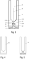
- Fig. 3 shows a front view of a slat 7 according to the device 1 according to the invention for the migration of aquatic animals.
- the lamella 7 is plate-shaped and is arranged in the device 1 transversely to the longitudinal axis 8 of the channel body 6.
- the slat 7 has a lower cutout 22 that is open at the bottom and is delimited at the top by a cross element 20.
- the cross-sectional area of the lower cutout 22 is dimensioned such that the web 10 of the cover layer 9 can be accommodated in the lower cutout 22.
- the upper edge of the transverse element 20 has a contour 21 which slopes down from both sides towards the center of the channel and which defines a lower boundary of an upper cutout 23 of the lamella which extends upwards from the transverse element 20.
- the contour 21 is designed as a curved contour.
- the contour 21 of the upper edge of the transverse element 20 is symmetrical with respect to a width bisector 24 of the lamella.
- the contour 21 of the upper edge of the transverse element 20 consists of curved sections along its entire course.
- a central section 21A of the curved contour 21 of the upper edge of the transverse element 20 is convex, ie the central section 21A in relation to the width bisector 24 is trained.
- the convex central portion 21A is formed in a parabolic shape with the parabolic vertex S as the lowest point, so that the parabolic central portion 21A extends upward symmetrically to the width bisector 24. Ie the width bisector 24 simultaneously represents the parabolic axis.
- the convex central section 21A of the curved contour 21 is adjoined on both sides by concave side sections 21B, 21C. These two concave side sections 21B, 21C form the end sections of the curved contour 21 of the upper edge of the transverse element 20, ie the concave side sections 21B, 21C open into the side walls of the upper cutout 23.
- the upper cutout 23 of the slat is open at the top.
- a contour with straight sections can be provided, which in the simplest embodiment can be implemented by a V-neck. As mentioned at the beginning, such an embodiment has poorer hydraulic properties compared to a curved contour.
- the transverse element 20 is designed as an integrated part of the slat 7. In an alternative embodiment, however, the transverse element 20 can be designed as an independent, preferably replaceable component.
- the advantageous hydraulic properties of the lamella 7 of the device 1 according to the invention for the migration of aquatic animals are compared with the hydraulic properties of lamellas of the original Denil fish pass and the modified Denil fish pass according to AT 520908.
- Fig. 4 Shown in front view is a slat 30 commonly used in the original Denil fishway.
- Fig. 5 a front view of a two-part slat 31 of the modified Denil fish pass according to AT 520908 is shown.
- FIGS. 6A, 6B and 6C show contour plots of the flow velocity distribution at the slats 30 of the original Denil fish pass ( Fig. 6A ), on the slats 31 of the modified Denil fish pass according to AT 520908 ( Fig. 6B ), and on the slats 7 of the device 1 according to the invention for the migration of aquatic animals ( Fig. 6C ).
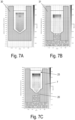
- FIGS. 7A, 7B and 7C show contour plots of the turbulent kinetic energy at the lamellae 30 of the original Denil fish pass ( Fig. 7A ), on the slats 31 of the modified Denil fish pass according to AT 520908 ( Fig. 7B ), and on the slats 7 of the device 1 according to the invention for the migration of aquatic animals ( Fig. 7C ).
- the flow speeds in the device 1 according to the invention for the migration of aquatic animals are higher in sections than in the original Denil fish pass, but are significantly lower than in the modified Denil fish pass. If one looks at the distribution of the flow speed, it can be seen that in the device 1 according to the invention for the migration of aquatic animals, the flow speed in a region from the curved contour 21 of the transverse element 20 upwards to approximately the middle of the height of the upper cutout 23 is similarly low as in the case of the device 1 according to the invention original Denil fish pass and only above that has higher values. However, this lower area is relevant for the rise of small aquatic animals and aquatic animals living near the bottom.
- the flow speed in the modified Denil fish pass is generally higher than in the device 1 according to the invention for the migration of aquatic animals and than in the original Denil fish pass.
- the device 1 according to the invention for the migration of aquatic animals experiences a significant reduction in flow speeds compared to the prior art while maintaining the low turbulent kinetic energy.
- the illustration of turbulent kinetic energy in the original Denil fishway in Fig. 7A also clearly illustrates that in the original Denil fish pass, high turbulence was recorded near the bottom, which explains the limited passability for a wide range of species. This problem is completely solved by the present invention.
- the present invention is characterized by a significant reduction in the flow speed, which therefore enables weaker and smaller aquatic animals to overcome the device 1 for the migration of aquatic animals, even with larger types of construction.
- a key achievement of the present invention lies in the hydraulic resilience, so that the fish pass can be maintained even when the water flow is reduced, as is the case during fish trap monitoring (the fish trap cards are continuously moved by floating materials such as leaves, which reduces the flow), which is a standardized method for the biotic testing of fish passage aids is to be expected.
Landscapes
- Engineering & Computer Science (AREA)
- General Engineering & Computer Science (AREA)
- Life Sciences & Earth Sciences (AREA)
- Marine Sciences & Fisheries (AREA)
- Mechanical Engineering (AREA)
- Civil Engineering (AREA)
- Structural Engineering (AREA)
- Catching Or Destruction (AREA)
- Artificial Fish Reefs (AREA)
Priority Applications (2)
| Application Number | Priority Date | Filing Date | Title |
|---|---|---|---|
| EP22196360.6A EP4339375B1 (fr) | 2022-09-19 | 2022-09-19 | Dispositif pour la migration d'animaux aquatiques |
| US18/469,669 US12516483B2 (en) | 2022-09-19 | 2023-09-19 | Device for the migration of aquatic animals |
Applications Claiming Priority (1)
| Application Number | Priority Date | Filing Date | Title |
|---|---|---|---|
| EP22196360.6A EP4339375B1 (fr) | 2022-09-19 | 2022-09-19 | Dispositif pour la migration d'animaux aquatiques |
Publications (3)
| Publication Number | Publication Date |
|---|---|
| EP4339375A1 true EP4339375A1 (fr) | 2024-03-20 |
| EP4339375C0 EP4339375C0 (fr) | 2024-12-11 |
| EP4339375B1 EP4339375B1 (fr) | 2024-12-11 |
Family
ID=83362553
Family Applications (1)
| Application Number | Title | Priority Date | Filing Date |
|---|---|---|---|
| EP22196360.6A Active EP4339375B1 (fr) | 2022-09-19 | 2022-09-19 | Dispositif pour la migration d'animaux aquatiques |
Country Status (2)
| Country | Link |
|---|---|
| US (1) | US12516483B2 (fr) |
| EP (1) | EP4339375B1 (fr) |
Citations (3)
| Publication number | Priority date | Publication date | Assignee | Title |
|---|---|---|---|---|
| US1621170A (en) | 1925-07-17 | 1927-03-15 | Landau William Charles | Fishway |
| EP3214225A1 (fr) | 2016-03-02 | 2017-09-06 | MVM Holding GmbH | Dispositif de migration d'animaux aquatiques vers des barrières dans des eaux |
| DE102018251767A1 (de) * | 2018-01-29 | 2019-08-01 | flusslauf Ingenieurbüro für Gewässerökologie und Wasserbau e.U. | Vorrichtung zur Wanderung von Wassertieren an Barrieren in Gewässern |
Family Cites Families (6)
| Publication number | Priority date | Publication date | Assignee | Title |
|---|---|---|---|---|
| DE3741986A1 (de) * | 1987-04-01 | 1988-10-20 | Wilhelm Dipl Ing Bruns | Fischpass |
| JPH0881945A (ja) * | 1994-09-09 | 1996-03-26 | Hokoku Kogyo Co Ltd | デニール式組立魚道 |
| US7708494B2 (en) * | 2006-10-26 | 2010-05-04 | Mclaughlin Consulting Company | Water diversion system and method having hydraulic chute, screen assembly and wedge wire screen |
| US20170241093A1 (en) * | 2016-02-22 | 2017-08-24 | South Dakota State University | Small stream fish ladder |
| CN112942264B (zh) * | 2021-02-22 | 2022-06-07 | 中国长江三峡集团有限公司 | 一种浮坞自适应调节的补水鱼道 |
| CN113882332B (zh) * | 2021-12-08 | 2022-02-08 | 交通运输部天津水运工程科学研究所 | 一种双侧竖缝式鱼道池室减淤结构、鱼道及其减淤方法 |
-
2022
- 2022-09-19 EP EP22196360.6A patent/EP4339375B1/fr active Active
-
2023
- 2023-09-19 US US18/469,669 patent/US12516483B2/en active Active
Patent Citations (4)
| Publication number | Priority date | Publication date | Assignee | Title |
|---|---|---|---|---|
| US1621170A (en) | 1925-07-17 | 1927-03-15 | Landau William Charles | Fishway |
| EP3214225A1 (fr) | 2016-03-02 | 2017-09-06 | MVM Holding GmbH | Dispositif de migration d'animaux aquatiques vers des barrières dans des eaux |
| DE102018251767A1 (de) * | 2018-01-29 | 2019-08-01 | flusslauf Ingenieurbüro für Gewässerökologie und Wasserbau e.U. | Vorrichtung zur Wanderung von Wassertieren an Barrieren in Gewässern |
| AT520908A2 (de) | 2018-01-29 | 2019-08-15 | Guenter Parthl | Vorrichtung zur Wanderung von Wassertieren an Barrieren in Gewässern |
Non-Patent Citations (1)
| Title |
|---|
| MALLEN-COOPER M ET AL: "Optimising Denil fishways for passage of small and large fishes", FISHERIES MANAGEMENT AND ECOLOGY, JOHN WILEY & SONS, INC, HOBOKEN, USA, vol. 14, no. 1, 5 January 2007 (2007-01-05), pages 61 - 71, XP071918074, ISSN: 0969-997X, DOI: 10.1111/J.1365-2400.2006.00524.X * |
Also Published As
| Publication number | Publication date |
|---|---|
| US12516483B2 (en) | 2026-01-06 |
| EP4339375C0 (fr) | 2024-12-11 |
| US20240093450A1 (en) | 2024-03-21 |
| EP4339375B1 (fr) | 2024-12-11 |
Similar Documents
| Publication | Publication Date | Title |
|---|---|---|
| EP0901540B1 (fr) | Echelle a poissons | |
| EP2098640B1 (fr) | Dispositif de descente d'anguilles sur des bâtiments maritimes | |
| EP3149247B1 (fr) | Passe à poissons | |
| DE3247602A1 (de) | Schutzvorrichtung zur verringerung der windgeschwindigkeit | |
| EP4339375B1 (fr) | Dispositif pour la migration d'animaux aquatiques | |
| AT520908B1 (de) | Vorrichtung zur Wanderung von Wassertieren an Barrieren in Gewässern | |
| DE102009044069B4 (de) | Fischaufstiegsanlage zur Überwindung eines Wanderhindernisses in einem Fließgewässer | |
| AT399179B (de) | Heberwehr mit einer nach unten gerichteten oberwasserseitig angeordneten einlassöffnung | |
| DE102023124723A1 (de) | Nullschwelle für eine Tür | |
| DE102005048764B4 (de) | Kombinierter Längssandfang und Fettfang | |
| DE102010037926A1 (de) | Wasserkraftanlage | |
| DE2416417A1 (de) | Regulierbare belueftungseinrichtung | |
| WO2021044051A1 (fr) | Dispositif comprenant un élément de type nasse pivotant | |
| EP3214225A1 (fr) | Dispositif de migration d'animaux aquatiques vers des barrières dans des eaux | |
| DE102010002935B4 (de) | Stabrechen | |
| DE2559080A1 (de) | Regenabflussgitter | |
| EP3173530A1 (fr) | Dispositif de migration d'animaux aquatiques vers des barrières dans des eaux | |
| EP4520886A1 (fr) | Caniveau d'écoulement et procédé de nettoyage d'un caniveau d'écoulement | |
| DE102022106289A1 (de) | Abdeckrost einer Oberflächenentwässerungseinrichtung sowie Oberflächenentwässerungseinrichtung mit einem solchen Abdeckrost | |
| DE1708515C3 (de) | Ausbau für eine Gefällestrecke eines Wasserlaufes | |
| DE3741986A1 (de) | Fischpass | |
| EP4488461A1 (fr) | Recouvrement de caniveau et caniveau d'écoulement doté de celui-ci | |
| DE8236117U1 (de) | Schutzvorrichtung zur Verringerung der Windgeschwindigkeit | |
| AT12581U1 (de) | Anordnung an fliessenden gewässern | |
| DE20105479U1 (de) | Rückhalteanlage |
Legal Events
| Date | Code | Title | Description |
|---|---|---|---|
| PUAI | Public reference made under article 153(3) epc to a published international application that has entered the european phase |
Free format text: ORIGINAL CODE: 0009012 |
|
| STAA | Information on the status of an ep patent application or granted ep patent |
Free format text: STATUS: THE APPLICATION HAS BEEN PUBLISHED |
|
| AK | Designated contracting states |
Kind code of ref document: A1 Designated state(s): AL AT BE BG CH CY CZ DE DK EE ES FI FR GB GR HR HU IE IS IT LI LT LU LV MC MK MT NL NO PL PT RO RS SE SI SK SM TR |
|
| STAA | Information on the status of an ep patent application or granted ep patent |
Free format text: STATUS: REQUEST FOR EXAMINATION WAS MADE |
|
| 17P | Request for examination filed |
Effective date: 20240408 |
|
| RBV | Designated contracting states (corrected) |
Designated state(s): AL AT BE BG CH CY CZ DE DK EE ES FI FR GB GR HR HU IE IS IT LI LT LU LV MC MK MT NL NO PL PT RO RS SE SI SK SM TR |
|
| GRAP | Despatch of communication of intention to grant a patent |
Free format text: ORIGINAL CODE: EPIDOSNIGR1 |
|
| STAA | Information on the status of an ep patent application or granted ep patent |
Free format text: STATUS: GRANT OF PATENT IS INTENDED |
|
| RIC1 | Information provided on ipc code assigned before grant |
Ipc: A01K 79/00 20060101ALN20240726BHEP Ipc: E02B 8/08 20060101AFI20240726BHEP |
|
| INTG | Intention to grant announced |
Effective date: 20240809 |
|
| GRAS | Grant fee paid |
Free format text: ORIGINAL CODE: EPIDOSNIGR3 |
|
| GRAA | (expected) grant |
Free format text: ORIGINAL CODE: 0009210 |
|
| STAA | Information on the status of an ep patent application or granted ep patent |
Free format text: STATUS: THE PATENT HAS BEEN GRANTED |
|
| AK | Designated contracting states |
Kind code of ref document: B1 Designated state(s): AL AT BE BG CH CY CZ DE DK EE ES FI FR GB GR HR HU IE IS IT LI LT LU LV MC MK MT NL NO PL PT RO RS SE SI SK SM TR |
|
| REG | Reference to a national code |
Ref country code: GB Ref legal event code: FG4D Free format text: NOT ENGLISH |
|
| REG | Reference to a national code |
Ref country code: CH Ref legal event code: EP |
|
| REG | Reference to a national code |
Ref country code: DE Ref legal event code: R096 Ref document number: 502022002362 Country of ref document: DE |
|
| REG | Reference to a national code |
Ref country code: IE Ref legal event code: FG4D Free format text: LANGUAGE OF EP DOCUMENT: GERMAN |
|
| U01 | Request for unitary effect filed |
Effective date: 20250107 |
|
| U07 | Unitary effect registered |
Designated state(s): AT BE BG DE DK EE FI FR IT LT LU LV MT NL PT RO SE SI Effective date: 20250115 |
|
| PG25 | Lapsed in a contracting state [announced via postgrant information from national office to epo] |
Ref country code: HR Free format text: LAPSE BECAUSE OF FAILURE TO SUBMIT A TRANSLATION OF THE DESCRIPTION OR TO PAY THE FEE WITHIN THE PRESCRIBED TIME-LIMIT Effective date: 20241211 |
|
| PG25 | Lapsed in a contracting state [announced via postgrant information from national office to epo] |
Ref country code: ES Free format text: LAPSE BECAUSE OF FAILURE TO SUBMIT A TRANSLATION OF THE DESCRIPTION OR TO PAY THE FEE WITHIN THE PRESCRIBED TIME-LIMIT Effective date: 20241211 |
|
| PG25 | Lapsed in a contracting state [announced via postgrant information from national office to epo] |
Ref country code: NO Free format text: LAPSE BECAUSE OF FAILURE TO SUBMIT A TRANSLATION OF THE DESCRIPTION OR TO PAY THE FEE WITHIN THE PRESCRIBED TIME-LIMIT Effective date: 20250311 |
|
| PG25 | Lapsed in a contracting state [announced via postgrant information from national office to epo] |
Ref country code: GR Free format text: LAPSE BECAUSE OF FAILURE TO SUBMIT A TRANSLATION OF THE DESCRIPTION OR TO PAY THE FEE WITHIN THE PRESCRIBED TIME-LIMIT Effective date: 20250312 |
|
| PG25 | Lapsed in a contracting state [announced via postgrant information from national office to epo] |
Ref country code: RS Free format text: LAPSE BECAUSE OF FAILURE TO SUBMIT A TRANSLATION OF THE DESCRIPTION OR TO PAY THE FEE WITHIN THE PRESCRIBED TIME-LIMIT Effective date: 20250311 |
|
| PG25 | Lapsed in a contracting state [announced via postgrant information from national office to epo] |
Ref country code: SM Free format text: LAPSE BECAUSE OF FAILURE TO SUBMIT A TRANSLATION OF THE DESCRIPTION OR TO PAY THE FEE WITHIN THE PRESCRIBED TIME-LIMIT Effective date: 20241211 |
|
| PG25 | Lapsed in a contracting state [announced via postgrant information from national office to epo] |
Ref country code: PL Free format text: LAPSE BECAUSE OF FAILURE TO SUBMIT A TRANSLATION OF THE DESCRIPTION OR TO PAY THE FEE WITHIN THE PRESCRIBED TIME-LIMIT Effective date: 20241211 |
|
| PG25 | Lapsed in a contracting state [announced via postgrant information from national office to epo] |
Ref country code: IS Free format text: LAPSE BECAUSE OF FAILURE TO SUBMIT A TRANSLATION OF THE DESCRIPTION OR TO PAY THE FEE WITHIN THE PRESCRIBED TIME-LIMIT Effective date: 20250411 |
|
| PG25 | Lapsed in a contracting state [announced via postgrant information from national office to epo] |
Ref country code: SK Free format text: LAPSE BECAUSE OF FAILURE TO SUBMIT A TRANSLATION OF THE DESCRIPTION OR TO PAY THE FEE WITHIN THE PRESCRIBED TIME-LIMIT Effective date: 20241211 |
|
| PG25 | Lapsed in a contracting state [announced via postgrant information from national office to epo] |
Ref country code: CZ Free format text: LAPSE BECAUSE OF FAILURE TO SUBMIT A TRANSLATION OF THE DESCRIPTION OR TO PAY THE FEE WITHIN THE PRESCRIBED TIME-LIMIT Effective date: 20241211 |
|
| PLBE | No opposition filed within time limit |
Free format text: ORIGINAL CODE: 0009261 |
|
| STAA | Information on the status of an ep patent application or granted ep patent |
Free format text: STATUS: NO OPPOSITION FILED WITHIN TIME LIMIT |
|
| U20 | Renewal fee for the european patent with unitary effect paid |
Year of fee payment: 4 Effective date: 20250925 |
|
| 26N | No opposition filed |
Effective date: 20250912 |