EP4259376B1 - Méthode de fabrication d'aube de turbine haute pression comportant une cavité sous baignoire - Google Patents
Méthode de fabrication d'aube de turbine haute pression comportant une cavité sous baignoire Download PDFInfo
- Publication number
- EP4259376B1 EP4259376B1 EP21847990.5A EP21847990A EP4259376B1 EP 4259376 B1 EP4259376 B1 EP 4259376B1 EP 21847990 A EP21847990 A EP 21847990A EP 4259376 B1 EP4259376 B1 EP 4259376B1
- Authority
- EP
- European Patent Office
- Prior art keywords
- wall
- bottom wall
- blade
- face
- suction
- Prior art date
- Legal status (The legal status is an assumption and is not a legal conclusion. Google has not performed a legal analysis and makes no representation as to the accuracy of the status listed.)
- Active
Links
Images

Classifications
-
- F—MECHANICAL ENGINEERING; LIGHTING; HEATING; WEAPONS; BLASTING
- F01—MACHINES OR ENGINES IN GENERAL; ENGINE PLANTS IN GENERAL; STEAM ENGINES
- F01D—NON-POSITIVE DISPLACEMENT MACHINES OR ENGINES, e.g. STEAM TURBINES
- F01D5/00—Blades; Blade-carrying members; Heating, heat-insulating, cooling or antivibration means on the blades or the members
- F01D5/12—Blades
- F01D5/14—Form or construction
- F01D5/20—Specially-shaped blade tips to seal space between tips and stator
-
- B—PERFORMING OPERATIONS; TRANSPORTING
- B22—CASTING; POWDER METALLURGY
- B22F—WORKING METALLIC POWDER; MANUFACTURE OF ARTICLES FROM METALLIC POWDER; MAKING METALLIC POWDER; APPARATUS OR DEVICES SPECIALLY ADAPTED FOR METALLIC POWDER
- B22F10/00—Additive manufacturing of workpieces or articles from metallic powder
- B22F10/20—Direct sintering or melting
- B22F10/25—Direct deposition of metal particles, e.g. direct metal deposition [DMD] or laser engineered net shaping [LENS]
-
- B—PERFORMING OPERATIONS; TRANSPORTING
- B22—CASTING; POWDER METALLURGY
- B22F—WORKING METALLIC POWDER; MANUFACTURE OF ARTICLES FROM METALLIC POWDER; MAKING METALLIC POWDER; APPARATUS OR DEVICES SPECIALLY ADAPTED FOR METALLIC POWDER
- B22F10/00—Additive manufacturing of workpieces or articles from metallic powder
- B22F10/20—Direct sintering or melting
- B22F10/28—Powder bed fusion, e.g. selective laser melting [SLM] or electron beam melting [EBM]
-
- B—PERFORMING OPERATIONS; TRANSPORTING
- B22—CASTING; POWDER METALLURGY
- B22F—WORKING METALLIC POWDER; MANUFACTURE OF ARTICLES FROM METALLIC POWDER; MAKING METALLIC POWDER; APPARATUS OR DEVICES SPECIALLY ADAPTED FOR METALLIC POWDER
- B22F5/00—Manufacture of workpieces or articles from metallic powder characterised by the special shape of the product
- B22F5/04—Manufacture of workpieces or articles from metallic powder characterised by the special shape of the product of turbine blades
-
- B—PERFORMING OPERATIONS; TRANSPORTING
- B22—CASTING; POWDER METALLURGY
- B22F—WORKING METALLIC POWDER; MANUFACTURE OF ARTICLES FROM METALLIC POWDER; MAKING METALLIC POWDER; APPARATUS OR DEVICES SPECIALLY ADAPTED FOR METALLIC POWDER
- B22F7/00—Manufacture of composite layers, workpieces, or articles, comprising metallic powder, by sintering the powder, with or without compacting wherein at least one part is obtained by sintering or compression
- B22F7/06—Manufacture of composite layers, workpieces, or articles, comprising metallic powder, by sintering the powder, with or without compacting wherein at least one part is obtained by sintering or compression of composite workpieces or articles from parts, e.g. to form tipped tools
- B22F7/062—Manufacture of composite layers, workpieces, or articles, comprising metallic powder, by sintering the powder, with or without compacting wherein at least one part is obtained by sintering or compression of composite workpieces or articles from parts, e.g. to form tipped tools involving the connection or repairing of preformed parts
-
- B—PERFORMING OPERATIONS; TRANSPORTING
- B23—MACHINE TOOLS; METAL-WORKING NOT OTHERWISE PROVIDED FOR
- B23K—SOLDERING OR UNSOLDERING; WELDING; CLADDING OR PLATING BY SOLDERING OR WELDING; CUTTING BY APPLYING HEAT LOCALLY, e.g. FLAME CUTTING; WORKING BY LASER BEAM
- B23K26/00—Working by laser beam, e.g. welding, cutting or boring
- B23K26/0006—Working by laser beam, e.g. welding, cutting or boring taking account of the properties of the material involved
-
- B—PERFORMING OPERATIONS; TRANSPORTING
- B23—MACHINE TOOLS; METAL-WORKING NOT OTHERWISE PROVIDED FOR
- B23K—SOLDERING OR UNSOLDERING; WELDING; CLADDING OR PLATING BY SOLDERING OR WELDING; CUTTING BY APPLYING HEAT LOCALLY, e.g. FLAME CUTTING; WORKING BY LASER BEAM
- B23K26/00—Working by laser beam, e.g. welding, cutting or boring
- B23K26/34—Laser welding for purposes other than joining
- B23K26/342—Build-up welding
-
- B—PERFORMING OPERATIONS; TRANSPORTING
- B23—MACHINE TOOLS; METAL-WORKING NOT OTHERWISE PROVIDED FOR
- B23P—METAL-WORKING NOT OTHERWISE PROVIDED FOR; COMBINED OPERATIONS; UNIVERSAL MACHINE TOOLS
- B23P15/00—Making specific metal objects by operations not covered by a single other subclass or a group in this subclass
- B23P15/006—Making specific metal objects by operations not covered by a single other subclass or a group in this subclass turbine wheels
-
- B—PERFORMING OPERATIONS; TRANSPORTING
- B23—MACHINE TOOLS; METAL-WORKING NOT OTHERWISE PROVIDED FOR
- B23P—METAL-WORKING NOT OTHERWISE PROVIDED FOR; COMBINED OPERATIONS; UNIVERSAL MACHINE TOOLS
- B23P15/00—Making specific metal objects by operations not covered by a single other subclass or a group in this subclass
- B23P15/04—Making specific metal objects by operations not covered by a single other subclass or a group in this subclass turbine or like blades from several pieces
-
- B—PERFORMING OPERATIONS; TRANSPORTING
- B33—ADDITIVE MANUFACTURING TECHNOLOGY
- B33Y—ADDITIVE MANUFACTURING, i.e. MANUFACTURING OF THREE-DIMENSIONAL [3D] OBJECTS BY ADDITIVE DEPOSITION, ADDITIVE AGGLOMERATION OR ADDITIVE LAYERING, e.g. BY 3D PRINTING, STEREOLITHOGRAPHY OR SELECTIVE LASER SINTERING
- B33Y10/00—Processes of additive manufacturing
-
- B—PERFORMING OPERATIONS; TRANSPORTING
- B33—ADDITIVE MANUFACTURING TECHNOLOGY
- B33Y—ADDITIVE MANUFACTURING, i.e. MANUFACTURING OF THREE-DIMENSIONAL [3D] OBJECTS BY ADDITIVE DEPOSITION, ADDITIVE AGGLOMERATION OR ADDITIVE LAYERING, e.g. BY 3D PRINTING, STEREOLITHOGRAPHY OR SELECTIVE LASER SINTERING
- B33Y80/00—Products made by additive manufacturing
-
- F—MECHANICAL ENGINEERING; LIGHTING; HEATING; WEAPONS; BLASTING
- F01—MACHINES OR ENGINES IN GENERAL; ENGINE PLANTS IN GENERAL; STEAM ENGINES
- F01D—NON-POSITIVE DISPLACEMENT MACHINES OR ENGINES, e.g. STEAM TURBINES
- F01D25/00—Component parts, details, or accessories, not provided for in, or of interest apart from, other groups
- F01D25/08—Cooling; Heating; Heat-insulation
- F01D25/12—Cooling
-
- F—MECHANICAL ENGINEERING; LIGHTING; HEATING; WEAPONS; BLASTING
- F01—MACHINES OR ENGINES IN GENERAL; ENGINE PLANTS IN GENERAL; STEAM ENGINES
- F01D—NON-POSITIVE DISPLACEMENT MACHINES OR ENGINES, e.g. STEAM TURBINES
- F01D5/00—Blades; Blade-carrying members; Heating, heat-insulating, cooling or antivibration means on the blades or the members
- F01D5/12—Blades
- F01D5/14—Form or construction
- F01D5/147—Construction, i.e. structural features, e.g. of weight-saving hollow blades
-
- F—MECHANICAL ENGINEERING; LIGHTING; HEATING; WEAPONS; BLASTING
- F01—MACHINES OR ENGINES IN GENERAL; ENGINE PLANTS IN GENERAL; STEAM ENGINES
- F01D—NON-POSITIVE DISPLACEMENT MACHINES OR ENGINES, e.g. STEAM TURBINES
- F01D5/00—Blades; Blade-carrying members; Heating, heat-insulating, cooling or antivibration means on the blades or the members
- F01D5/12—Blades
- F01D5/14—Form or construction
- F01D5/18—Hollow blades, i.e. blades with cooling or heating channels or cavities; Heating, heat-insulating or cooling means on blades
-
- F—MECHANICAL ENGINEERING; LIGHTING; HEATING; WEAPONS; BLASTING
- F01—MACHINES OR ENGINES IN GENERAL; ENGINE PLANTS IN GENERAL; STEAM ENGINES
- F01D—NON-POSITIVE DISPLACEMENT MACHINES OR ENGINES, e.g. STEAM TURBINES
- F01D5/00—Blades; Blade-carrying members; Heating, heat-insulating, cooling or antivibration means on the blades or the members
- F01D5/12—Blades
- F01D5/14—Form or construction
- F01D5/18—Hollow blades, i.e. blades with cooling or heating channels or cavities; Heating, heat-insulating or cooling means on blades
- F01D5/186—Film cooling
-
- F—MECHANICAL ENGINEERING; LIGHTING; HEATING; WEAPONS; BLASTING
- F01—MACHINES OR ENGINES IN GENERAL; ENGINE PLANTS IN GENERAL; STEAM ENGINES
- F01D—NON-POSITIVE DISPLACEMENT MACHINES OR ENGINES, e.g. STEAM TURBINES
- F01D5/00—Blades; Blade-carrying members; Heating, heat-insulating, cooling or antivibration means on the blades or the members
- F01D5/12—Blades
- F01D5/14—Form or construction
- F01D5/18—Hollow blades, i.e. blades with cooling or heating channels or cavities; Heating, heat-insulating or cooling means on blades
- F01D5/187—Convection cooling
-
- B—PERFORMING OPERATIONS; TRANSPORTING
- B23—MACHINE TOOLS; METAL-WORKING NOT OTHERWISE PROVIDED FOR
- B23K—SOLDERING OR UNSOLDERING; WELDING; CLADDING OR PLATING BY SOLDERING OR WELDING; CUTTING BY APPLYING HEAT LOCALLY, e.g. FLAME CUTTING; WORKING BY LASER BEAM
- B23K2101/00—Articles made by soldering, welding or cutting
- B23K2101/001—Turbines
-
- B—PERFORMING OPERATIONS; TRANSPORTING
- B23—MACHINE TOOLS; METAL-WORKING NOT OTHERWISE PROVIDED FOR
- B23P—METAL-WORKING NOT OTHERWISE PROVIDED FOR; COMBINED OPERATIONS; UNIVERSAL MACHINE TOOLS
- B23P6/00—Restoring or reconditioning objects
- B23P6/002—Repairing turbine components, e.g. moving or stationary blades, rotors
- B23P6/007—Repairing turbine components, e.g. moving or stationary blades, rotors using only additive methods, e.g. build-up welding
-
- F—MECHANICAL ENGINEERING; LIGHTING; HEATING; WEAPONS; BLASTING
- F05—INDEXING SCHEMES RELATING TO ENGINES OR PUMPS IN VARIOUS SUBCLASSES OF CLASSES F01-F04
- F05D—INDEXING SCHEME FOR ASPECTS RELATING TO NON-POSITIVE-DISPLACEMENT MACHINES OR ENGINES, GAS-TURBINES OR JET-PROPULSION PLANTS
- F05D2230/00—Manufacture
- F05D2230/10—Manufacture by removing material
- F05D2230/11—Manufacture by removing material by electrochemical methods
-
- F—MECHANICAL ENGINEERING; LIGHTING; HEATING; WEAPONS; BLASTING
- F05—INDEXING SCHEMES RELATING TO ENGINES OR PUMPS IN VARIOUS SUBCLASSES OF CLASSES F01-F04
- F05D—INDEXING SCHEME FOR ASPECTS RELATING TO NON-POSITIVE-DISPLACEMENT MACHINES OR ENGINES, GAS-TURBINES OR JET-PROPULSION PLANTS
- F05D2230/00—Manufacture
- F05D2230/10—Manufacture by removing material
- F05D2230/12—Manufacture by removing material by spark erosion methods
-
- F—MECHANICAL ENGINEERING; LIGHTING; HEATING; WEAPONS; BLASTING
- F05—INDEXING SCHEMES RELATING TO ENGINES OR PUMPS IN VARIOUS SUBCLASSES OF CLASSES F01-F04
- F05D—INDEXING SCHEME FOR ASPECTS RELATING TO NON-POSITIVE-DISPLACEMENT MACHINES OR ENGINES, GAS-TURBINES OR JET-PROPULSION PLANTS
- F05D2230/00—Manufacture
- F05D2230/20—Manufacture essentially without removing material
- F05D2230/21—Manufacture essentially without removing material by casting
- F05D2230/211—Manufacture essentially without removing material by casting by precision casting, e.g. microfusing or investment casting
-
- F—MECHANICAL ENGINEERING; LIGHTING; HEATING; WEAPONS; BLASTING
- F05—INDEXING SCHEMES RELATING TO ENGINES OR PUMPS IN VARIOUS SUBCLASSES OF CLASSES F01-F04
- F05D—INDEXING SCHEME FOR ASPECTS RELATING TO NON-POSITIVE-DISPLACEMENT MACHINES OR ENGINES, GAS-TURBINES OR JET-PROPULSION PLANTS
- F05D2230/00—Manufacture
- F05D2230/20—Manufacture essentially without removing material
- F05D2230/22—Manufacture essentially without removing material by sintering
-
- F—MECHANICAL ENGINEERING; LIGHTING; HEATING; WEAPONS; BLASTING
- F05—INDEXING SCHEMES RELATING TO ENGINES OR PUMPS IN VARIOUS SUBCLASSES OF CLASSES F01-F04
- F05D—INDEXING SCHEME FOR ASPECTS RELATING TO NON-POSITIVE-DISPLACEMENT MACHINES OR ENGINES, GAS-TURBINES OR JET-PROPULSION PLANTS
- F05D2230/00—Manufacture
- F05D2230/20—Manufacture essentially without removing material
- F05D2230/23—Manufacture essentially without removing material by permanently joining parts together
- F05D2230/232—Manufacture essentially without removing material by permanently joining parts together by welding
- F05D2230/234—Laser welding
-
- F—MECHANICAL ENGINEERING; LIGHTING; HEATING; WEAPONS; BLASTING
- F05—INDEXING SCHEMES RELATING TO ENGINES OR PUMPS IN VARIOUS SUBCLASSES OF CLASSES F01-F04
- F05D—INDEXING SCHEME FOR ASPECTS RELATING TO NON-POSITIVE-DISPLACEMENT MACHINES OR ENGINES, GAS-TURBINES OR JET-PROPULSION PLANTS
- F05D2230/00—Manufacture
- F05D2230/30—Manufacture with deposition of material
-
- F—MECHANICAL ENGINEERING; LIGHTING; HEATING; WEAPONS; BLASTING
- F05—INDEXING SCHEMES RELATING TO ENGINES OR PUMPS IN VARIOUS SUBCLASSES OF CLASSES F01-F04
- F05D—INDEXING SCHEME FOR ASPECTS RELATING TO NON-POSITIVE-DISPLACEMENT MACHINES OR ENGINES, GAS-TURBINES OR JET-PROPULSION PLANTS
- F05D2230/00—Manufacture
- F05D2230/30—Manufacture with deposition of material
- F05D2230/31—Layer deposition
-
- F—MECHANICAL ENGINEERING; LIGHTING; HEATING; WEAPONS; BLASTING
- F05—INDEXING SCHEMES RELATING TO ENGINES OR PUMPS IN VARIOUS SUBCLASSES OF CLASSES F01-F04
- F05D—INDEXING SCHEME FOR ASPECTS RELATING TO NON-POSITIVE-DISPLACEMENT MACHINES OR ENGINES, GAS-TURBINES OR JET-PROPULSION PLANTS
- F05D2240/00—Components
- F05D2240/20—Rotors
- F05D2240/30—Characteristics of rotor blades, i.e. of any element transforming dynamic fluid energy to or from rotational energy and being attached to a rotor
- F05D2240/307—Characteristics of rotor blades, i.e. of any element transforming dynamic fluid energy to or from rotational energy and being attached to a rotor related to the tip of a rotor blade
-
- F—MECHANICAL ENGINEERING; LIGHTING; HEATING; WEAPONS; BLASTING
- F05—INDEXING SCHEMES RELATING TO ENGINES OR PUMPS IN VARIOUS SUBCLASSES OF CLASSES F01-F04
- F05D—INDEXING SCHEME FOR ASPECTS RELATING TO NON-POSITIVE-DISPLACEMENT MACHINES OR ENGINES, GAS-TURBINES OR JET-PROPULSION PLANTS
- F05D2250/00—Geometry
- F05D2250/30—Arrangement of components
- F05D2250/31—Arrangement of components according to the direction of their main axis or their axis of rotation
- F05D2250/311—Arrangement of components according to the direction of their main axis or their axis of rotation the axes being in line
-
- F—MECHANICAL ENGINEERING; LIGHTING; HEATING; WEAPONS; BLASTING
- F05—INDEXING SCHEMES RELATING TO ENGINES OR PUMPS IN VARIOUS SUBCLASSES OF CLASSES F01-F04
- F05D—INDEXING SCHEME FOR ASPECTS RELATING TO NON-POSITIVE-DISPLACEMENT MACHINES OR ENGINES, GAS-TURBINES OR JET-PROPULSION PLANTS
- F05D2250/00—Geometry
- F05D2250/60—Structure; Surface texture
- F05D2250/62—Structure; Surface texture smooth or fine
-
- F—MECHANICAL ENGINEERING; LIGHTING; HEATING; WEAPONS; BLASTING
- F05—INDEXING SCHEMES RELATING TO ENGINES OR PUMPS IN VARIOUS SUBCLASSES OF CLASSES F01-F04
- F05D—INDEXING SCHEME FOR ASPECTS RELATING TO NON-POSITIVE-DISPLACEMENT MACHINES OR ENGINES, GAS-TURBINES OR JET-PROPULSION PLANTS
- F05D2250/00—Geometry
- F05D2250/60—Structure; Surface texture
- F05D2250/62—Structure; Surface texture smooth or fine
- F05D2250/621—Structure; Surface texture smooth or fine polished
-
- F—MECHANICAL ENGINEERING; LIGHTING; HEATING; WEAPONS; BLASTING
- F05—INDEXING SCHEMES RELATING TO ENGINES OR PUMPS IN VARIOUS SUBCLASSES OF CLASSES F01-F04
- F05D—INDEXING SCHEME FOR ASPECTS RELATING TO NON-POSITIVE-DISPLACEMENT MACHINES OR ENGINES, GAS-TURBINES OR JET-PROPULSION PLANTS
- F05D2260/00—Function
- F05D2260/20—Heat transfer, e.g. cooling
- F05D2260/202—Heat transfer, e.g. cooling by film cooling
-
- F—MECHANICAL ENGINEERING; LIGHTING; HEATING; WEAPONS; BLASTING
- F05—INDEXING SCHEMES RELATING TO ENGINES OR PUMPS IN VARIOUS SUBCLASSES OF CLASSES F01-F04
- F05D—INDEXING SCHEME FOR ASPECTS RELATING TO NON-POSITIVE-DISPLACEMENT MACHINES OR ENGINES, GAS-TURBINES OR JET-PROPULSION PLANTS
- F05D2260/00—Function
- F05D2260/60—Fluid transfer
- F05D2260/607—Preventing clogging or obstruction of flow paths by dirt, dust, or foreign particles
-
- Y—GENERAL TAGGING OF NEW TECHNOLOGICAL DEVELOPMENTS; GENERAL TAGGING OF CROSS-SECTIONAL TECHNOLOGIES SPANNING OVER SEVERAL SECTIONS OF THE IPC; TECHNICAL SUBJECTS COVERED BY FORMER USPC CROSS-REFERENCE ART COLLECTIONS [XRACs] AND DIGESTS
- Y02—TECHNOLOGIES OR APPLICATIONS FOR MITIGATION OR ADAPTATION AGAINST CLIMATE CHANGE
- Y02P—CLIMATE CHANGE MITIGATION TECHNOLOGIES IN THE PRODUCTION OR PROCESSING OF GOODS
- Y02P10/00—Technologies related to metal processing
- Y02P10/25—Process efficiency
-
- Y—GENERAL TAGGING OF NEW TECHNOLOGICAL DEVELOPMENTS; GENERAL TAGGING OF CROSS-SECTIONAL TECHNOLOGIES SPANNING OVER SEVERAL SECTIONS OF THE IPC; TECHNICAL SUBJECTS COVERED BY FORMER USPC CROSS-REFERENCE ART COLLECTIONS [XRACs] AND DIGESTS
- Y02—TECHNOLOGIES OR APPLICATIONS FOR MITIGATION OR ADAPTATION AGAINST CLIMATE CHANGE
- Y02T—CLIMATE CHANGE MITIGATION TECHNOLOGIES RELATED TO TRANSPORTATION
- Y02T50/00—Aeronautics or air transport
- Y02T50/60—Efficient propulsion technologies, e.g. for aircraft
-
- Y—GENERAL TAGGING OF NEW TECHNOLOGICAL DEVELOPMENTS; GENERAL TAGGING OF CROSS-SECTIONAL TECHNOLOGIES SPANNING OVER SEVERAL SECTIONS OF THE IPC; TECHNICAL SUBJECTS COVERED BY FORMER USPC CROSS-REFERENCE ART COLLECTIONS [XRACs] AND DIGESTS
- Y10—TECHNICAL SUBJECTS COVERED BY FORMER USPC
- Y10T—TECHNICAL SUBJECTS COVERED BY FORMER US CLASSIFICATION
- Y10T29/00—Metal working
- Y10T29/49—Method of mechanical manufacture
- Y10T29/49316—Impeller making
- Y10T29/4932—Turbomachine making
- Y10T29/49321—Assembling individual fluid flow interacting members, e.g., blades, vanes, buckets, on rotary support member
Definitions
- the invention relates to the manufacture of a turbomachine blade such as a turbojet blade, a turboprop blade, a helicopter gas turbine blade, an APU (Auxiliary Power Unit), or even an industrial gas turbine blade. .
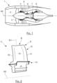
- a turbojet identified by 1 in the figure 1
- the air is admitted into an inlet sleeve 2 to pass through a fan comprising a series of rotating blades 3 before splitting into a central primary flow and a secondary flow surrounding the primary flow.
- the primary flow is compressed by stages of compressors 4 and 6 before reaching a combustion chamber 7, after which it expands passing through turbines 8, before being evacuated by generating thrust.
- the secondary flow is propelled directly by the fan to generate the main thrust.
- Each turbine 8 comprises series of blades oriented radially and regularly spaced around a rotation shaft AX rotatably mounted in an external casing 9 surrounding the assembly.
- Cooling of the blades is ensured by circulating in each blade air taken for example from the compressor level or in the secondary flow and admitted at the base of the blade, this air being evacuated through holes passing through the walls of these blades.
- Such a blade has a top having the shape of a bathtub, and which may include a cavity under the bathtub in which air circulates to improve cooling of the top.
- each hollow portion must be delimited by a core which must be rigidly held in a mold during the casting operation.
- the complexity of the shape of a blade comprising a cavity under a bathtub makes its manufacture by foundry particularly delicate, and therefore expensive.
- the object of the invention is to provide a solution to simplify the manufacture of a blade comprising a cavity under a bathtub improving the cooling of the blade tip.
- This solution makes it possible to form a cavity under a bathtub without having to use a complex arrangement of cores to constitute the raw part, which allows the molding operation to be significantly simplified and the production scrap rate to be reduced.
- One embodiment of the invention also relates to a process thus defined, in which the additive manufacturing process is a process by deposition of metal powder fused by laser beam.
- One embodiment of the invention also relates to a method thus defined, comprising the formation of dust removal holes in the bottom wall.
- One embodiment of the invention also relates to a method thus defined, in which the dust removal holes in the bottom wall have oblique orientations directed towards the edges of the intrados and/or extrados walls.
- One embodiment of the invention also relates to a method thus defined, comprising the formation in the dividing wall of dust removal holes which are offset relative to the dust removal holes in the bottom wall.
- One embodiment of the invention also relates to a method thus defined, in which each dust removal hole of the separating wall is at a distance from the periphery of the blade formed by the intrados and extrados walls which is less at the distance separating the corresponding dust removal hole in the bottom wall from the periphery of the blade.
- One embodiment of the invention also relates to a method thus defined, comprising the formation of dust removal holes passing through the bottom wall, each dust removal hole in the bottom wall being located opposite a dust removal hole. dust removal from the dividing wall.
- One embodiment of the invention also relates to a method thus defined, in which as many dust removal holes are formed passing through the bottom wall as there are dust removal holes passing through the dividing wall.
- One embodiment of the invention also relates to a method thus defined, comprising the formation in the blade of an air supply conduit for the cavity under the bathtub.
- a blade according to the invention marked 11 comprises a foot P by which it is fixed to a rotor element not shown, and a blade 12 carried by this foot P, the foot and the blade being separated by a platform 13.
- the blade 12 has a twisted shape around an axis EV called the span axis which is perpendicular to the axis AX. It comprises a base by which it is connected to the platform 13 and which extends radially to a vertex S constituting the free end of this blade 12.
- the two main walls of the blade 12, which are its lower surface wall 14 and its upper surface wall 15, are spaced from one another in the central part of the blade 11, and they are joined at the level of the leading edge 16 of the blade 11 and the trailing edge 17 of this blade 11.
- the top S of the blade 11 comprises a bottom wall 18 substantially normal to the direction EV, which extends from the intrados wall to the extrados wall.
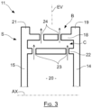
- This back wall (see Figure 3 ) is set back towards the axis AX relative to the terminal ends of the free edges 19 and 21 of the intrados walls 14 and extrados 15.
- This bottom wall 18 jointly delimits with these edges 19 and 21 a hollow portion open in direction opposite to the axis AX, called bathtub and marked by B, which is located at the level of the vertex S.
- the blade comprises a cavity under bathtub C, delimited in the direction EV by the bottom wall 18 and by a dividing wall 22 extending from the intrados wall 14 to the extrados wall 15, being spaced apart from this wall 18 and substantially parallel to it.
- the blade 11 comprises cooling ducts located between the lower surface walls 14 and upper surface walls 15, which extend between the foot P and the dividing wall 22 essentially in the span direction EV. These ducts are supplied by fresh air collected at the level of the foot P to ensure the cooling of the different regions of the blade.
- the dust removal holes such as holes 23 and 24 have a larger section than other cooling holes in the blade, so as to ensure evacuation outside the blade of dust or impurities present in the fresh air collected at the base of the blade and coming from the external environment.
- each dust removal hole 24 in the bottom wall 18 is located opposite a corresponding dust removal hole 23 in the dividing wall 22 in the direction EV, and the number number of dust removal holes in the bottom wall is the same as the number of dust removal holes in the dividing wall. More generally, the total section of the holes in the bottom wall is equal to the total section of the holes in the dividing wall to ensure effective dust evacuation.
- the dust removal holes 23 and 24 are offset relative to each other, so that the air coming from the holes 23 entering the cavity under the bathtub C forms jets oriented towards the bottom wall 18 in order to ensure cooling by jet impact on this bottom wall 18. Cooling by jet impact makes it possible to obtain an increased heat exchange coefficient, and thereby ensure effective cooling.
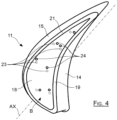
- each hole 24 formed in the bottom wall 18 is offset relative to the corresponding hole 23 formed in the dividing wall, that is to say that the projection of a hole 23 on the bottom wall 18 in the direction d
- the span EV is located at a distance from the corresponding hole 24 formed in this bottom wall 18.
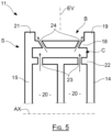
- the dust removal holes formed in the walls 18 and 22 extend in the span direction EV. But it may be advantageous to provide that the holes 24 formed in the bottom wall 18 extend in a direction oblique to the span direction, so as to constitute air jets oriented towards the edges 19 and 21 so as to cool them.
- each hole 23 formed in the dividing wall is then advantageously located to the right of a corresponding hole 24 formed in the bottom wall 18, in the span direction.
- the air jet generated by a hole 23 is thus oriented directly towards a corresponding hole 24 so as to pass through it almost directly to ensure cooling.
- effective of the portion of the edge 19 or 21 ventilated by this hole 24 whose orientation is oblique.
- each hole in the dividing wall opens at least partly onto a hole in the corresponding bottom wall, which also makes it possible to ensure cooling by impact before evacuation of dust.
- the orientation of the holes 24 towards the edges 19 and 21 ensures cooling by impact of these edges.
- the cooling of the edges 19 and 21 can be further increased by providing a conduit 26 opening directly into the cavity under the bath C to supply it with a greater flow of fresh air, in order to increase the flow of the dust removal holes 24 oriented towards edges 19 and 21.
- the external face of the bottom wall 18 can be covered with a thermal barrier coating.
- the blade 11 is obtained by first manufacturing a raw part from a foundry constituting a body of the blade comprising its foot P, the intrados 14 and extrados 15 walls, and at least the separating wall 22, and then constituting the bottom wall 18 by additive manufacturing on this raw part to delimit the cavity under the bathtub C and the bathtub B.
- Obtaining the raw part is ensured by foundry, with a mold and a set of cores comprising at least two elements spaced from one another along the span direction EV by a distance corresponding to the thickness of the dividing wall.
- These core elements are installed in the mold while being spaced from the internal faces of this mold to delimit with these internal faces the intrados 14 and extrados 15 walls.
- the constitution of the bottom wall 18 is ensured by positioning the raw part in a gripping tool, before positioning in the vicinity of the separating wall 22 a deposition apparatus mainly comprising a metal powder deposition nozzle and a laser beam for merging the powder deposited.
- Such equipment makes it possible to carry out an additive manufacturing operation according to the so-called LMD process, meaning Laser Metal Deposition.
- Other equipment can be provided to ensure the constitution of the dividing wall 22 by additive manufacturing, according to the LMD process or according to other similar processes.
- the blade can be positioned in such a way that its axis of span EV extends in a horizontal direction or substantially inclined during this operation of adding metallic material, so that the wall is constituted by additive manufacturing according to a direction close to vertical, so as to minimize undercut angles during the process.
- this bottom wall 18 can possibly be reworked by machining, for example by electroerosion or chemical treatment, to reduce the roughness of the external surface of this bottom wall and thus reduce the coefficient of external heat exchange which reduces surface heating.
- the bottom wall 18 is constituted by adding metallic material so as to have a thickness which is not constant, so for example as to delimit at the level of its internal face, that is to say the one closest to the foot P, a recess at each dust removal hole.
- Each recess then constitutes an enlarged mouth of the corresponding dust removal hole to promote the admission of air from the cavity under the bathtub C.
- These recesses then make it possible to reduce the number of holes 24 formed in the bottom wall 18, and/or to reduce the section of these holes to increase the speed of the air in the cavity under the bathtub to improve its cooling.
Landscapes
- Engineering & Computer Science (AREA)
- Mechanical Engineering (AREA)
- General Engineering & Computer Science (AREA)
- Manufacturing & Machinery (AREA)
- Physics & Mathematics (AREA)
- Chemical & Material Sciences (AREA)
- Materials Engineering (AREA)
- Optics & Photonics (AREA)
- Plasma & Fusion (AREA)
- Composite Materials (AREA)
- Architecture (AREA)
- Turbine Rotor Nozzle Sealing (AREA)
- Powder Metallurgy (AREA)
Description
- L'invention concerne la fabrication d'une aube de turbomachine telle qu'une aube de turboréacteur, de turbopropulseur, de turbine à gaz d'hélicoptère, d'APU (Unité Auxiliaire de Puissance), ou encore une aube de turbine à gaz industrielle.
- Dans un turboréacteur, repéré par 1 dans la
figure 1 , l'air est admis dans une manche d'entrée 2 pour traverser une soufflante comportant une série de pales rotatives 3 avant de se scinder en un flux primaire central et un flux secondaire entourant le flux primaire. - Le flux primaire est compressé par des étages de compesseurs 4 et 6 avant d'atteindre une chambre de combustion 7, après quoi il se détend en traversant des turbines 8, avant d'être évacué en générant une poussée. Le flux secondaire est quant à lui propulsé directement par la soufflante pour générer la poussée principale.
- Chaque turbine 8 comporte des séries d'aubes orientées radialement et régulièrement espacées autour d'un arbre de rotation AX monté en rotation dans un carter externe 9 entourant l'ensemble.
- Le refroidissement des aubes est assuré en faisant circuler dans chaque aube de l'air prélevé par exemple au nieau du compresseur ou dans le flux secondaire et admis en pied d'aube, cet air étant évacué par des trous traversant les parois de ces aubes.
- Une telle aube comporte un sommet ayant une forme de baignoire, et pouvant comporter une cavité sous baignoire dans laquelle circule de l'air pour améliorer le refroidissement du sommet.
- Il s'ensuit qu'une telle aube présente des formes internes et externes complexes rendant sa fabrication par fonderie délicate : chaque portion creuse doit être délimitée par un noyau devant être rigidement maintenu dans un moule durant l'opération de coulée. En pratique, la complexité de forme d'une aube comportant une cavité sous baignoire rend sa fabrication par fonderie particulièrement délicate, et par là-même coûteuse.
- Les documents
FR3037829 FR3037972 FR3037972A1 US2020/256196 divulguent des aubes de formes analogues, mais nécessitant des procédés de fabrication complexes qui induisent des coûts de fabrication élevés. - Dans ce cadre, l'objet de l'invention est d'apporter une solution pour simplifier la fabrication d'une aube comportant une cavité sous baignoire améliorant le refroidissement du sommet d'aube.
- A cet effet, conformément à la revendication 1, a pour objet un procédé de fabrication d'une aube de turbomachine comprenant une paroi d'intrados et une paroi d'extrados espacées l'une de l'autre, cette aube comprenant un sommet avec :
- une paroi de fond s'étendant de la paroi d'intrados à la paroi d'extrados la paroi d'intrados et la paroi d'extrados comprenant chacune un bord libre s'étendant au-delà de cette paroi de fond pour délimiter conjointement avec cette paroi de fond une forme de baignoire au sommet de l'aube ;
- une paroi séparatrice s'étendant de la paroi d'intrados à la paroi d'extrados en étant espacée de la paroi de fond pour délimiter avec cette paroi de fond une cavité sous baignoire ;
- une étape de moulage pour constituer au moins la paroi d'intrados, la paroi d'extrados et la paroi séparatrice ;
- une étape de constitution de la paroi de fond avec un procédé de fabrication additive par apport de matière métallique.
- Cette solution permet de constituer une cavité sous baignoire sans devoir utiliser un agencement de noyaux complexe pour constituer la pièce brute, ce qui permet de simplifier significativement l'opération de moulage et de diminuer le taux de rebut en production.
- Un mode de réalisation de l'invention concerne également un procédé ainsi défini, dans lequel le procédé de fabrication additive est un procédé par dépôt de poudre métallique fusionnée par rayon laser.
- Un mode de réalisation de l'invention concerne également un procédé ainsi défini, comportant la formation de trous de dépoussiérage dans la paroi de fond.
- Un mode de réalisation de l'invention concerne également un procédé ainsi défini, dans lequel les trous de dépoussiérage de la paroi de fond ont des orientations obliques dirigées vers les bords des parois d'intrados et/ou d'extrados.
- Un mode de réalisation de l'invention concerne également un procédé ainsi défini, comportant la formation dans la paroi séparatrice de trous de dépoussiérage qui sont décalés par rapport aux trous de dépoussiérage de la paroi de fond.
- Un mode de réalisation de l'invention concerne également un procédé ainsi défini, dans lequel chaque trou de dépoussiérage de la paroi séparatrice est à une distance de la périphérie de l'aube formée par les parois d'intrados et d'extrados qui est inférieure à la distance séparant le trou de dépoussiérage correspondant de la paroi de fond de la périphérie de l'aube.
- Un mode de réalisation de l'invention concerne également un procédé ainsi défini, comportant la formation de trous de dépoussiérage traversant la paroi de fond, chaque trou de dépoussiérage de la paroi de fond étant situé en vis-à-vis d'un trou de dépoussiérage de la paroi séparatrice.
- Un mode de réalisation de l'invention concerne également un procédé ainsi défini, dans lequel on forme autant de trous de dépoussiérage traversant la paroi de fond que de trous de dépoussiérage traversant la paroi séparatrice.
- Un mode de réalisation de l'invention concerne également un procédé ainsi défini, comportant la formation dans l'aube d'un conduit d'alimentation en air de la cavité sous baignoire.
-
- La
figure 1 est une vue en coupe longitudinale d'un turboréacteur connu ; - La
figure 2 est une vue d'ensemble en perspective d'une aube selon l'invention ; - La
figure 3 est une vue en coupe selon un plan normal à l'axe de rotation d'une aube selon un premier mode de réalisation de l'invention ; - La
figure 4 est vue en perspective du sommet d'une aube selon le premier mode de réalisation de l'invention ; - La
figure 5 est une vue en coupe selon un plan normal à l'axe de rotation d'une aube selon un deuxième mode de réalisation de l'invention ; - La
figure 6 est une vue en coupe selon un plan normal à l'axe de rotation d'une aube selon un troisième mode de réalisation de l'invention. - Sur la
figure 2 , une aube selon l'invention repérée par 11 comprend un pied P par lequel elle est fixée à un élément de rotor non représenté, et une pale 12 portée par ce pied P, le pied et la pale étant séparés par une plateforme 13. - La pale 12 a une forme vrillée autour d'un axe EV dit axe d'envergure qui est perpendiculaire à l'axe AX. Elle comprend une base par laquelle elle est raccordée à la plateforme 13 et qui se prolonge radialement jusqu'à un sommet S constituant l'extrémité libre de cette pale 12.
- Les deux parois principales de la pale 12, qui sont sa paroi d'intrados 14 et sa paroi d'extrados 15 sont espacées l'une de l'autre en partie centrale de l'aube 11, et elles sont réunies au niveau du bord d'attaque 16 de l'aube 11 et du bord de fuite 17 de cette aube 11.
- Le sommet S de l'aube 11 comporte une paroi de fond 18 sensiblement normale à la direction EV, qui s'étend de la paroi d'intrados à la paroi d'extrados. Cette paroi de fond (voir
figure 3 ) est en retrait vers l'axe AX par rapport aux extrémités terminales des bords libres 19 et 21 des parois d'intrados 14 et d'extrados 15. Cette paroi de fond 18 délimite conjointement avec ces bords 19 et 21 une portion creuse ouverte en direction opposée à l'axe AX, appelée baignoire et repérée par B, qui est située au niveau du sommet S. - Comme visible sur la
figure 3 , l'aube comporte une cavité sous baignoire C, délimitée selon la direction EV par la paroi de fond 18 et par une paroi séparatrice 22 s'étendant de la paroi d'intrados 14 à la paroi d'extrados 15, en étant espacée de cette paroi 18 et sensiblement parallèle à celle-ci. - L'aube 11 comporte des conduits de refroidissement situés entre les parois d'intrados 14 et d'extrados 15, qui s'étendent entre le pied P et la paroi séparatrice 22 esentiellement selon la direction d'envergure EV. Ces conduits sont alimentés par de l'air frais collecté au niveau du pied P pour assurer le refroidissement des différentes régions de l'aube.
- L'air circulant dans ces conduits, repérés par 20 sur les figures, est évacué par des trous de dépoussiérage 23 traversant la paroi séparatrice 22, puis par des trous de dépoussiérage 24 complémentaires traversant la paroi de fond 18. L'air issu des conduits de refroidissement est ainsi admis dans la cavité sous baignoire C par les trous 23, et il est évacué vers la baignoire B à travers les trous 24. Cet air de dépoussiérage assure ainsi le refroidissement de la cavité sous baignoire C et de la paroi de fond 18, c'est-à-dire du sommet d'aube, sans devoir augmenter le débit d'air alimentant l'aube pour son refroidissement.
- Les trous de dépoussiérage tels que les trous 23 et 24 présentent une section plus importante que d'autres trous de refroidissement de l'aube, de manière à assurer une évacuation hors de l'aube de poussières ou impuretés présentes dans l'air frais collecté en pied d'aube et provenant de l'environnement extérieur.
- Pour assurer valablement le dépoussiérage de l'aube, chaque trou de dépoussiérage 24 de la paroi de fond 18 est situé en vis-à-vis d'un trou de dépoussiérage correspondant 23 de la paroi séparatrice 22 selon la direction EV, et le nombre de trous de dépoussiérage de la paroi de fond est identique au nombre de trous de dépoussiérage de la paroi séparatrice. Plus généralement, la section totale des trous de la paroi de fond est égale à la section totale des trous de la paroi séparatrice pour assurer valablement l'évacuation des poussières.
- Alternativement, et comme illustré sur les
figures 3 et4 , les trous de dépoussiérage 23 et 24 sont décalés les uns par rapport aux autres, pour que l'air issu des trous 23 entrant dans la cavité sous baignoire C forme des jets orientés vers la paroi de fond 18 afin d'assurer un refroidissement par impact de jet sur cette paroi de fond 18. Le refroidissement par impact de jet permet d'obtenir un coefficient d'échange thermique accru, et par là-même d'assurer un refroidissement efficace. - Plus particulièrement, et comme visible sur la
figure 4 , chaque trou 24 formé dans la paroi de fond 18 est décalé par rapport au trou correspondant 23 formé dans la paroi séparatrice, c'est-à-dire que la projection d'un trou 23 sur la paroi de fond 18 selon la direction d'envergure EV est située à distance du trou 24 correspondant formé dans cette paroi de fond 18. - Dans l'exemple des
figures 3 et4 , les trous de dépoussiérage formés dans les parois 18 et 22 s'étendent selon la direction d'envergure EV. Mais il peut être avantageux de prévoir que les trous 24 formés dans la paroi de fond 18 s'étendent selon une direction oblique par rapport à la direction d'envergure, de manière à constituer des jets d'air orientés vers les bords 19 et 21 de façon à les refroidir. - Pour accroître le refroidissement des bords 19 et 21, chaque trou 23 formé dans la paroi séparatrice est alors avantageusement situé au droit d'un trou correspondant 24 formé dans la paroi de fond 18, selon la direction d'envergure. Le jet d'air généré par un trou 23 est ainsi orienté directement vers un trou 24 correspondant de façon à le traverser de façon quasiment directe pour assurer un refroidissement efficace de la portion du bord 19 ou 21 ventilée par ce trou 24 dont l'orientation est oblique. Ainsi, avantageusement, chaque trou de la paroi séparatrice débouche au moins en partie sur un trou de la paroi de fond correspondant, ce qui permet en outre d'assurer un refroidissement par impact avant évacuation des poussières. L'orientation des trous 24 vers les bords 19 et 21 permet d'assurer un refroidissement par impact de ces bords.
- Dans ce cas, il n'y a pas d'impact de l'air de refroidissement issu des trous 23 sur la paroi de fond 18 : le refroidissement des bords est alors favorisé par rapport à celui de la cavité sous baignoire C.
- Comme illustré sur la
figure 6 , le refroidissement des bords 19 et 21 peut encore être augmenté en prévoyant un conduit 26 débouchant directement dans la cavité sous baignoire C pour l'alimenter avec un plus grand débit d'air frais, afin d'accroître le débit des trous de dépoussiérage 24 orientés vers les bords 19 et 21. - Afin d'accroître la tenue thermique de l'aube, la face externe de la paroi de fond 18 peut être couverte d'un revêtement de barrière thermique.
- Selon l'invention, l'aube 11 est obtenue en fabriquant d'abord une pièce brute issue de fonderie constituant un corps de l'aube comprenant son pied P, les paroi d'intrados 14 et d'extrados 15, et au moins la paroi séparatrice 22, et en constituant ensuite la paroi de fond 18 par fabrication additive sur cette pièce brute pour délimiter la cavité sous baignoire C et la baignoire B.
- L'obtention de la pièce brute est assurée par fonderie, avec un moule et un ensemble de noyaux comprenant au moins deux éléments espacés l'un de l'autre le long de la direction d'envergure EV d'une distance correspondant à l'épaisseur de la paroi séparatrice. Ces éléments de noyaux sont installés dans le moule en étant espacés des faces internes de ce moule pour délimiter avec ces faces internes les parois d'intrados 14 et d'extrados 15.
- La constitution de la paroi de fond 18 est assurée en positionnant la pièce brute dans un outil de préhension, avant de positionner au voisinage de la paroi séparatrice 22 un appareillage de dépôt comprenant principalement une buse de dépôt de poudre métallique et un faisceau laser pour fusionner la poudre déposée.
- Un tel appareillage permet d'assurer une opération de fabrication additive selon le procédé dit LMD, signifiant Laser Metal Deposition. D'autres appareillages peuvent être prévus pour assurer la constitution de la paroi séparatrice 22 par fabrication additive, selon le procédé LMD ou selon d'autres procédés analogues.
- Des couches métalliques successives sont alors déposées et fusionnées pour constituer de manière homogène la paroi de fond 18, l'appareillage étant mobile afin de couvrir par balayage toute l'étendue de la paroi de fond 18 à constituer. Eventuellement, l'aube peut être positionnée de telle manière que son axe d'envergure EV s'étende selon une direction horizontale ou bien sensiblement inclinée lors de cette opération d'apport de matière métallique, pour que la paroi soit constitutuée par fabrication additive selon une direction proche de la verticale, de manière à minimiser les angles de contre-dépouille durant le processus.
- Après avoir été constituée par apport de matière métallique, cette paroi de fond 18 peut éventuellement être reprise par usinage, par exemple par électroérosion ou traitement chimique, pour réduire la rugosité de la surface externe de cette paroi de fond et ainsi diminuer le coefficient d'échange thermique externe ce qui permet de réduire l'échauffement de la surface.
- Avantageusement, la paroi de fond 18 est constituée par apport de matière métallique de manière à présenter un épaisseur qui est non constante, de façon par exemple à délimiter au niveau de sa face interne, c'est-à-dire la plus proche du pied P, un évidement au niveau de chaque trou de dépoussiérage. Chaque évidement constitue alors une embouchure élargie du trou de dépoussiérage correspondant pour favoriser l'admission d'air issu de la cavité sous baignoire C. Ces évidements permettent alors de diminuer le nombre de trous 24 formés dans la paroi de fond 18, et/ou de réduire la section de ces trous pour augmenter la vitesse de l'air dans la cavité sous baignoire pour améliorer son refroidissement.
Claims (9)
- Procédé de fabrication d'une aube (11) de turbomachine comprenant une paroi d'intrados (14) et une paroi d'extrados (15) espacées l'une de l'autre, cette aube (11) comprenant un sommet (S) avec :- une paroi de fond (18) s'étendant de la paroi d'intrados (14) à la paroi d'extrados (15), la paroi d'intrados (14) et la paroi d'extrados (15) comprenant chacune un bord libre (19, 21) s'étendant au-delà de cette paroi de fond (18) pour délimiter conjointement avec cette paroi de fond (18) une forme de baignoire (B) au sommet (S) de l'aube (11) ;- une paroi séparatrice (22) s'étendant de la paroi d'intrados (14) à la paroi d'extrados (15) en étant espacée de la paroi de fond (18) pour délimiter avec cette paroi de fond (18) une cavité sous baignoire (C) ;le procédé comportant :- une étape de moulage pour constituer au moins la paroi d'intrados (14), la paroi d'extrados (15) et la paroi séparatrice (22) ;- une étape de constitution de la paroi de fond (18) avec un procédé de fabrication additive par apport de matière métallique.
- Procédé selon la revendication 1, dans lequel le procédé de fabrication additive est un procédé par dépôt de poudre métallique fusionnée par rayon laser, LMD.
- Procédé selon la revendication 1 ou 2, comportant la formation de trous de dépoussiérage (24) dans la paroi de fond (18).
- Procédé selon la revendication 3 dans lequel les trous de dépoussiérage (24) de la paroi de fond (18) ont des orientations obliques dirigées vers les bords (19, 21) des parois d'intrados (14) et/ou d'extrados (15).
- Procédé selon la revendication 3, comportant la formation dans la paroi séparatrice (22) de trous de dépoussiérage (23) qui sont décalés par rapport aux trous de dépoussiérage (24) de la paroi de fond (18).
- Procédé selon la revendication 5, dans lequel chaque trou de dépoussiérage (23) de la paroi séparatrice (22) est à une distance de la périphérie de l'aube formée par les parois d'intrados (14) et d'extrados (15) qui est inférieure à la distance séparant le trou de dépoussiérage (23) correspondant de la paroi de fond (18) de la périphérie de l'aube.
- Procédé selon la revendication 5, dans lequel chaque trou de dépoussiérage (24) de la paroi de fond (18) est situé au moins en partie en vis-à-vis d'un trou de dépoussiérage (23) de la paroi séparatrice (22).
- Procédé selon la revendication 5, dans lequel on forme autant de trous de dépoussiérage (24) traversant la paroi de fond (18) que de trous de dépoussiérage (23) traversant la paroi séparatrice (22).
- Procédé selon l'une des revendications 1 à 8, comportant la formation dans l'aube d'un conduit (26) d'alimentation en air de la cavité sous baignoire (C).
Applications Claiming Priority (2)
| Application Number | Priority Date | Filing Date | Title |
|---|---|---|---|
| FR2012855A FR3117389B1 (fr) | 2020-12-10 | 2020-12-10 | Aube de turbine haute pression comportant une cavité sous baignoire |
| PCT/FR2021/052242 WO2022123177A1 (fr) | 2020-12-10 | 2021-12-08 | Aube de turbine haute pression comportant une cavité sous baignoire |
Publications (2)
| Publication Number | Publication Date |
|---|---|
| EP4259376A1 EP4259376A1 (fr) | 2023-10-18 |
| EP4259376B1 true EP4259376B1 (fr) | 2024-07-31 |
Family
ID=75539404
Family Applications (1)
| Application Number | Title | Priority Date | Filing Date |
|---|---|---|---|
| EP21847990.5A Active EP4259376B1 (fr) | 2020-12-10 | 2021-12-08 | Méthode de fabrication d'aube de turbine haute pression comportant une cavité sous baignoire |
Country Status (5)
| Country | Link |
|---|---|
| US (1) | US12480408B2 (fr) |
| EP (1) | EP4259376B1 (fr) |
| CN (1) | CN116568455B (fr) |
| FR (1) | FR3117389B1 (fr) |
| WO (1) | WO2022123177A1 (fr) |
Families Citing this family (1)
| Publication number | Priority date | Publication date | Assignee | Title |
|---|---|---|---|---|
| EP4461927A1 (fr) | 2023-05-12 | 2024-11-13 | Doosan Enerbility Co., Ltd. | Corps d'écoulement pour turbine à gaz, turbine à gaz, procédé de fabrication d'un corps d'écoulement pour turbine à gaz et procédé de réparation d'un corps d'écoulement d'une turbine à gaz |
Family Cites Families (15)
| Publication number | Priority date | Publication date | Assignee | Title |
|---|---|---|---|---|
| US6224337B1 (en) * | 1999-09-17 | 2001-05-01 | General Electric Company | Thermal barrier coated squealer tip cavity |
| US7997865B1 (en) * | 2008-09-18 | 2011-08-16 | Florida Turbine Technologies, Inc. | Turbine blade with tip rail cooling and sealing |
| FR2982903B1 (fr) * | 2011-11-17 | 2014-02-21 | Snecma | Aube de turbine a gaz a decalage vers l'intrados des sections de tete et a canaux de refroidissement |
| US20150034266A1 (en) * | 2013-08-01 | 2015-02-05 | Siemens Energy, Inc. | Building and repair of hollow components |
| CN107109949A (zh) * | 2014-11-11 | 2017-08-29 | 西门子公司 | 带有轴向叶顶冷却回路的涡轮叶片 |
| DE102015210744A1 (de) * | 2015-06-12 | 2016-12-15 | Siemens Aktiengesellschaft | Verfahren zum Fertigen einer Turbinenschaufel |
| FR3037829B1 (fr) * | 2015-06-29 | 2017-07-21 | Snecma | Noyau pour le moulage d'une aube ayant des cavites superposees et comprenant un trou de depoussierage traversant une cavite de part en part |
| FR3037972B1 (fr) * | 2015-06-29 | 2017-07-21 | Snecma | Procede simplifiant le noyau utilise pour la fabrication d'une aube de turbomachine |
| DE102016216721A1 (de) * | 2016-09-05 | 2018-03-08 | Siemens Aktiengesellschaft | Verfahren zur additiven Herstellung mittels poröser Hilfsstruktur, Bauteil und Vorrichtung |
| US10370982B2 (en) * | 2017-02-03 | 2019-08-06 | DOOSAN Heavy Industries Construction Co., LTD | Double shelf squealer tip with impingement cooling of serpentine cooled turbine blades |
| US10610933B2 (en) * | 2017-02-22 | 2020-04-07 | General Electric Company | Method of manufacturing turbine airfoil with open tip casting and tip component thereof |
| WO2019177607A1 (fr) * | 2018-03-15 | 2019-09-19 | Siemens Energy, Inc. | Fabrication additive à fil de brasage laser d'un élément d'aube de turbine en super-solution avec refroidissement au-dessous de zéro |
| US10801334B2 (en) * | 2018-09-12 | 2020-10-13 | Raytheon Technologies Corporation | Cooling arrangement with purge partition |
| US11168571B2 (en) * | 2019-02-08 | 2021-11-09 | Raytheon Technologies Corporation | Airfoil having dead-end tip flag cavity |
| FR3101663B1 (fr) * | 2019-10-07 | 2021-10-01 | Safran Aircraft Engines | Procédé de rechargement d’une pale de turbomachine d’aéronef |
-
2020
- 2020-12-10 FR FR2012855A patent/FR3117389B1/fr active Active
-
2021
- 2021-12-08 US US18/256,372 patent/US12480408B2/en active Active
- 2021-12-08 WO PCT/FR2021/052242 patent/WO2022123177A1/fr not_active Ceased
- 2021-12-08 EP EP21847990.5A patent/EP4259376B1/fr active Active
- 2021-12-08 CN CN202180083314.0A patent/CN116568455B/zh active Active
Also Published As
| Publication number | Publication date |
|---|---|
| WO2022123177A1 (fr) | 2022-06-16 |
| CN116568455B (zh) | 2025-11-18 |
| CN116568455A (zh) | 2023-08-08 |
| FR3117389A1 (fr) | 2022-06-17 |
| US12480408B2 (en) | 2025-11-25 |
| EP4259376A1 (fr) | 2023-10-18 |
| FR3117389B1 (fr) | 2022-11-04 |
| US20240018872A1 (en) | 2024-01-18 |
Similar Documents
| Publication | Publication Date | Title |
|---|---|---|
| EP3149280B1 (fr) | Aube de turbine avec conduits de refroidissement optimisés | |
| EP3313597B1 (fr) | Procede de fabrication d'une aube comportant une baignoire integrant un muret | |
| EP3149282B1 (fr) | Aube de turbine à refroidissement optimisé au niveau de son bord de fuite comprenant des conduits amont et aval et des cavités laterales internes | |
| EP3441573B1 (fr) | Pale de ventilateur creuse en titane soudée par faisceau d'énergie à l'arrière de la cavité | |
| EP3529463B1 (fr) | Aube de turbomachine à refroidissement optimisé | |
| EP1273759A1 (fr) | Procédé et dispositif pour augmenter la durée de vie des aubes de turbine à gaz | |
| EP1365108A2 (fr) | Aube pour un moteur à turbine à gaz et procedé de fabrication d'une telle aube | |
| FR3037829A1 (fr) | Noyau pour le moulage d'une aube ayant des cavites superposees et comprenant un trou de depoussierage traversant une cavite de part en part | |
| EP3233328B1 (fr) | Procédé de fabrication d'une aube de turbomachine comportant un sommet pourvu d'une baignoire de type complexe | |
| EP3149281B1 (fr) | Aube de turbine comprenant un conduit central de refroidissement et deux cavités latérales jointives en aval du conduit central | |
| EP4259376A1 (fr) | Aube de turbine haute pression comportant une cavité sous baignoire | |
| EP3426896B1 (fr) | Aube refroidie de turbine | |
| EP3942156B1 (fr) | Insert tubulaire de refroidissement par impact pour un distributeur de turbomachine | |
| FR3037972A1 (fr) | Procede simplifiant le noyau utilise pour la fabrication d'une aube de turbomachine | |
| FR3154759A1 (fr) | Aube pour une turbomachine d’aeronef, noyau et procede de fabrication associes | |
| FR3148622A1 (fr) | Composant de turbomachine, turbomachine l’ayant et procédé de fabrication de celui-ci | |
| FR3079869A1 (fr) | Aube de turbine haute pression comportant une cavite morte presentant une reduction de section | |
| FR3097263A1 (fr) | Aube de turbomachine à refroidissement amélioré | |
| FR3061512A1 (fr) | Element radial de stator de turbomachine comportant un raidisseur |
Legal Events
| Date | Code | Title | Description |
|---|---|---|---|
| STAA | Information on the status of an ep patent application or granted ep patent |
Free format text: STATUS: UNKNOWN |
|
| STAA | Information on the status of an ep patent application or granted ep patent |
Free format text: STATUS: THE INTERNATIONAL PUBLICATION HAS BEEN MADE |
|
| PUAI | Public reference made under article 153(3) epc to a published international application that has entered the european phase |
Free format text: ORIGINAL CODE: 0009012 |
|
| STAA | Information on the status of an ep patent application or granted ep patent |
Free format text: STATUS: REQUEST FOR EXAMINATION WAS MADE |
|
| 17P | Request for examination filed |
Effective date: 20230605 |
|
| AK | Designated contracting states |
Kind code of ref document: A1 Designated state(s): AL AT BE BG CH CY CZ DE DK EE ES FI FR GB GR HR HU IE IS IT LI LT LU LV MC MK MT NL NO PL PT RO RS SE SI SK SM TR |
|
| DAV | Request for validation of the european patent (deleted) | ||
| DAX | Request for extension of the european patent (deleted) | ||
| GRAP | Despatch of communication of intention to grant a patent |
Free format text: ORIGINAL CODE: EPIDOSNIGR1 |
|
| STAA | Information on the status of an ep patent application or granted ep patent |
Free format text: STATUS: GRANT OF PATENT IS INTENDED |
|
| RIC1 | Information provided on ipc code assigned before grant |
Ipc: B23K 101/00 20060101ALN20240314BHEP Ipc: B22F 10/25 20210101ALI20240314BHEP Ipc: B22F 7/06 20060101ALI20240314BHEP Ipc: B22F 5/04 20060101ALI20240314BHEP Ipc: B33Y 80/00 20150101ALI20240314BHEP Ipc: B33Y 10/00 20150101ALI20240314BHEP Ipc: B23K 26/342 20140101ALI20240314BHEP Ipc: B23K 26/00 20140101ALI20240314BHEP Ipc: F01D 5/14 20060101ALI20240314BHEP Ipc: F01D 5/20 20060101ALI20240314BHEP Ipc: B23P 6/00 20060101ALI20240314BHEP Ipc: B23P 15/04 20060101AFI20240314BHEP |
|
| INTG | Intention to grant announced |
Effective date: 20240405 |
|
| RIN1 | Information on inventor provided before grant (corrected) |
Inventor name: ROLLINGER, ADRIEN, BERNARD, VINCENT Inventor name: PAQUIN, SYLVAIN Inventor name: PAGNONI, FILIPPO Inventor name: CARIOU, ROMAIN, PIERRE Inventor name: OSTINO, LEANDRE |
|
| GRAS | Grant fee paid |
Free format text: ORIGINAL CODE: EPIDOSNIGR3 |
|
| GRAA | (expected) grant |
Free format text: ORIGINAL CODE: 0009210 |
|
| STAA | Information on the status of an ep patent application or granted ep patent |
Free format text: STATUS: THE PATENT HAS BEEN GRANTED |
|
| AK | Designated contracting states |
Kind code of ref document: B1 Designated state(s): AL AT BE BG CH CY CZ DE DK EE ES FI FR GB GR HR HU IE IS IT LI LT LU LV MC MK MT NL NO PL PT RO RS SE SI SK SM TR |
|
| REG | Reference to a national code |
Ref country code: CH Ref legal event code: EP Ref country code: GB Ref legal event code: FG4D Free format text: NOT ENGLISH |
|
| REG | Reference to a national code |
Ref country code: DE Ref legal event code: R096 Ref document number: 602021016612 Country of ref document: DE |
|
| REG | Reference to a national code |
Ref country code: IE Ref legal event code: FG4D Free format text: LANGUAGE OF EP DOCUMENT: FRENCH |
|
| REG | Reference to a national code |
Ref country code: LT Ref legal event code: MG9D |
|
| REG | Reference to a national code |
Ref country code: NL Ref legal event code: MP Effective date: 20240731 |
|
| PG25 | Lapsed in a contracting state [announced via postgrant information from national office to epo] |
Ref country code: PT Free format text: LAPSE BECAUSE OF FAILURE TO SUBMIT A TRANSLATION OF THE DESCRIPTION OR TO PAY THE FEE WITHIN THE PRESCRIBED TIME-LIMIT Effective date: 20241202 |
|
| REG | Reference to a national code |
Ref country code: AT Ref legal event code: MK05 Ref document number: 1708041 Country of ref document: AT Kind code of ref document: T Effective date: 20240731 |
|
| PG25 | Lapsed in a contracting state [announced via postgrant information from national office to epo] |
Ref country code: PT Free format text: LAPSE BECAUSE OF FAILURE TO SUBMIT A TRANSLATION OF THE DESCRIPTION OR TO PAY THE FEE WITHIN THE PRESCRIBED TIME-LIMIT Effective date: 20241202 |
|
| PG25 | Lapsed in a contracting state [announced via postgrant information from national office to epo] |
Ref country code: NO Free format text: LAPSE BECAUSE OF FAILURE TO SUBMIT A TRANSLATION OF THE DESCRIPTION OR TO PAY THE FEE WITHIN THE PRESCRIBED TIME-LIMIT Effective date: 20241031 |
|
| PG25 | Lapsed in a contracting state [announced via postgrant information from national office to epo] |
Ref country code: NL Free format text: LAPSE BECAUSE OF FAILURE TO SUBMIT A TRANSLATION OF THE DESCRIPTION OR TO PAY THE FEE WITHIN THE PRESCRIBED TIME-LIMIT Effective date: 20240731 Ref country code: FI Free format text: LAPSE BECAUSE OF FAILURE TO SUBMIT A TRANSLATION OF THE DESCRIPTION OR TO PAY THE FEE WITHIN THE PRESCRIBED TIME-LIMIT Effective date: 20240731 Ref country code: GR Free format text: LAPSE BECAUSE OF FAILURE TO SUBMIT A TRANSLATION OF THE DESCRIPTION OR TO PAY THE FEE WITHIN THE PRESCRIBED TIME-LIMIT Effective date: 20241101 Ref country code: PL Free format text: LAPSE BECAUSE OF FAILURE TO SUBMIT A TRANSLATION OF THE DESCRIPTION OR TO PAY THE FEE WITHIN THE PRESCRIBED TIME-LIMIT Effective date: 20240731 |
|
| PG25 | Lapsed in a contracting state [announced via postgrant information from national office to epo] |
Ref country code: BG Free format text: LAPSE BECAUSE OF FAILURE TO SUBMIT A TRANSLATION OF THE DESCRIPTION OR TO PAY THE FEE WITHIN THE PRESCRIBED TIME-LIMIT Effective date: 20240731 |
|
| PG25 | Lapsed in a contracting state [announced via postgrant information from national office to epo] |
Ref country code: LV Free format text: LAPSE BECAUSE OF FAILURE TO SUBMIT A TRANSLATION OF THE DESCRIPTION OR TO PAY THE FEE WITHIN THE PRESCRIBED TIME-LIMIT Effective date: 20240731 |
|
| PG25 | Lapsed in a contracting state [announced via postgrant information from national office to epo] |
Ref country code: IS Free format text: LAPSE BECAUSE OF FAILURE TO SUBMIT A TRANSLATION OF THE DESCRIPTION OR TO PAY THE FEE WITHIN THE PRESCRIBED TIME-LIMIT Effective date: 20241130 Ref country code: AT Free format text: LAPSE BECAUSE OF FAILURE TO SUBMIT A TRANSLATION OF THE DESCRIPTION OR TO PAY THE FEE WITHIN THE PRESCRIBED TIME-LIMIT Effective date: 20240731 |
|
| PG25 | Lapsed in a contracting state [announced via postgrant information from national office to epo] |
Ref country code: HR Free format text: LAPSE BECAUSE OF FAILURE TO SUBMIT A TRANSLATION OF THE DESCRIPTION OR TO PAY THE FEE WITHIN THE PRESCRIBED TIME-LIMIT Effective date: 20240731 |
|
| PG25 | Lapsed in a contracting state [announced via postgrant information from national office to epo] |
Ref country code: ES Free format text: LAPSE BECAUSE OF FAILURE TO SUBMIT A TRANSLATION OF THE DESCRIPTION OR TO PAY THE FEE WITHIN THE PRESCRIBED TIME-LIMIT Effective date: 20240731 Ref country code: RS Free format text: LAPSE BECAUSE OF FAILURE TO SUBMIT A TRANSLATION OF THE DESCRIPTION OR TO PAY THE FEE WITHIN THE PRESCRIBED TIME-LIMIT Effective date: 20241031 |
|
| PG25 | Lapsed in a contracting state [announced via postgrant information from national office to epo] |
Ref country code: RS Free format text: LAPSE BECAUSE OF FAILURE TO SUBMIT A TRANSLATION OF THE DESCRIPTION OR TO PAY THE FEE WITHIN THE PRESCRIBED TIME-LIMIT Effective date: 20241031 Ref country code: PL Free format text: LAPSE BECAUSE OF FAILURE TO SUBMIT A TRANSLATION OF THE DESCRIPTION OR TO PAY THE FEE WITHIN THE PRESCRIBED TIME-LIMIT Effective date: 20240731 Ref country code: NO Free format text: LAPSE BECAUSE OF FAILURE TO SUBMIT A TRANSLATION OF THE DESCRIPTION OR TO PAY THE FEE WITHIN THE PRESCRIBED TIME-LIMIT Effective date: 20241031 Ref country code: NL Free format text: LAPSE BECAUSE OF FAILURE TO SUBMIT A TRANSLATION OF THE DESCRIPTION OR TO PAY THE FEE WITHIN THE PRESCRIBED TIME-LIMIT Effective date: 20240731 Ref country code: LV Free format text: LAPSE BECAUSE OF FAILURE TO SUBMIT A TRANSLATION OF THE DESCRIPTION OR TO PAY THE FEE WITHIN THE PRESCRIBED TIME-LIMIT Effective date: 20240731 Ref country code: IS Free format text: LAPSE BECAUSE OF FAILURE TO SUBMIT A TRANSLATION OF THE DESCRIPTION OR TO PAY THE FEE WITHIN THE PRESCRIBED TIME-LIMIT Effective date: 20241130 Ref country code: HR Free format text: LAPSE BECAUSE OF FAILURE TO SUBMIT A TRANSLATION OF THE DESCRIPTION OR TO PAY THE FEE WITHIN THE PRESCRIBED TIME-LIMIT Effective date: 20240731 Ref country code: GR Free format text: LAPSE BECAUSE OF FAILURE TO SUBMIT A TRANSLATION OF THE DESCRIPTION OR TO PAY THE FEE WITHIN THE PRESCRIBED TIME-LIMIT Effective date: 20241101 Ref country code: FI Free format text: LAPSE BECAUSE OF FAILURE TO SUBMIT A TRANSLATION OF THE DESCRIPTION OR TO PAY THE FEE WITHIN THE PRESCRIBED TIME-LIMIT Effective date: 20240731 Ref country code: ES Free format text: LAPSE BECAUSE OF FAILURE TO SUBMIT A TRANSLATION OF THE DESCRIPTION OR TO PAY THE FEE WITHIN THE PRESCRIBED TIME-LIMIT Effective date: 20240731 Ref country code: BG Free format text: LAPSE BECAUSE OF FAILURE TO SUBMIT A TRANSLATION OF THE DESCRIPTION OR TO PAY THE FEE WITHIN THE PRESCRIBED TIME-LIMIT Effective date: 20240731 Ref country code: AT Free format text: LAPSE BECAUSE OF FAILURE TO SUBMIT A TRANSLATION OF THE DESCRIPTION OR TO PAY THE FEE WITHIN THE PRESCRIBED TIME-LIMIT Effective date: 20240731 |
|
| PG25 | Lapsed in a contracting state [announced via postgrant information from national office to epo] |
Ref country code: DK Free format text: LAPSE BECAUSE OF FAILURE TO SUBMIT A TRANSLATION OF THE DESCRIPTION OR TO PAY THE FEE WITHIN THE PRESCRIBED TIME-LIMIT Effective date: 20240731 Ref country code: SM Free format text: LAPSE BECAUSE OF FAILURE TO SUBMIT A TRANSLATION OF THE DESCRIPTION OR TO PAY THE FEE WITHIN THE PRESCRIBED TIME-LIMIT Effective date: 20240731 Ref country code: RO Free format text: LAPSE BECAUSE OF FAILURE TO SUBMIT A TRANSLATION OF THE DESCRIPTION OR TO PAY THE FEE WITHIN THE PRESCRIBED TIME-LIMIT Effective date: 20240731 |
|
| PG25 | Lapsed in a contracting state [announced via postgrant information from national office to epo] |
Ref country code: EE Free format text: LAPSE BECAUSE OF FAILURE TO SUBMIT A TRANSLATION OF THE DESCRIPTION OR TO PAY THE FEE WITHIN THE PRESCRIBED TIME-LIMIT Effective date: 20240731 |
|
| PG25 | Lapsed in a contracting state [announced via postgrant information from national office to epo] |
Ref country code: CZ Free format text: LAPSE BECAUSE OF FAILURE TO SUBMIT A TRANSLATION OF THE DESCRIPTION OR TO PAY THE FEE WITHIN THE PRESCRIBED TIME-LIMIT Effective date: 20240731 |
|
| PG25 | Lapsed in a contracting state [announced via postgrant information from national office to epo] |
Ref country code: SK Free format text: LAPSE BECAUSE OF FAILURE TO SUBMIT A TRANSLATION OF THE DESCRIPTION OR TO PAY THE FEE WITHIN THE PRESCRIBED TIME-LIMIT Effective date: 20240731 Ref country code: IT Free format text: LAPSE BECAUSE OF FAILURE TO SUBMIT A TRANSLATION OF THE DESCRIPTION OR TO PAY THE FEE WITHIN THE PRESCRIBED TIME-LIMIT Effective date: 20240731 |
|
| REG | Reference to a national code |
Ref country code: DE Ref legal event code: R097 Ref document number: 602021016612 Country of ref document: DE |
|
| PLBE | No opposition filed within time limit |
Free format text: ORIGINAL CODE: 0009261 |
|
| STAA | Information on the status of an ep patent application or granted ep patent |
Free format text: STATUS: NO OPPOSITION FILED WITHIN TIME LIMIT |
|
| PG25 | Lapsed in a contracting state [announced via postgrant information from national office to epo] |
Ref country code: MC Free format text: LAPSE BECAUSE OF FAILURE TO SUBMIT A TRANSLATION OF THE DESCRIPTION OR TO PAY THE FEE WITHIN THE PRESCRIBED TIME-LIMIT Effective date: 20240731 |
|
| 26N | No opposition filed |
Effective date: 20250501 |
|
| REG | Reference to a national code |
Ref country code: CH Ref legal event code: PL |
|
| PG25 | Lapsed in a contracting state [announced via postgrant information from national office to epo] |
Ref country code: LU Free format text: LAPSE BECAUSE OF NON-PAYMENT OF DUE FEES Effective date: 20241208 |
|
| PG25 | Lapsed in a contracting state [announced via postgrant information from national office to epo] |
Ref country code: SE Free format text: LAPSE BECAUSE OF FAILURE TO SUBMIT A TRANSLATION OF THE DESCRIPTION OR TO PAY THE FEE WITHIN THE PRESCRIBED TIME-LIMIT Effective date: 20240731 |
|
| REG | Reference to a national code |
Ref country code: BE Ref legal event code: MM Effective date: 20241231 |
|
| PG25 | Lapsed in a contracting state [announced via postgrant information from national office to epo] |
Ref country code: BE Free format text: LAPSE BECAUSE OF NON-PAYMENT OF DUE FEES Effective date: 20241231 |
|
| PG25 | Lapsed in a contracting state [announced via postgrant information from national office to epo] |
Ref country code: CH Free format text: LAPSE BECAUSE OF NON-PAYMENT OF DUE FEES Effective date: 20241231 |
|
| PG25 | Lapsed in a contracting state [announced via postgrant information from national office to epo] |
Ref country code: IE Free format text: LAPSE BECAUSE OF NON-PAYMENT OF DUE FEES Effective date: 20241208 |
|
| PGFP | Annual fee paid to national office [announced via postgrant information from national office to epo] |
Ref country code: GB Payment date: 20251229 Year of fee payment: 5 |
|
| PGFP | Annual fee paid to national office [announced via postgrant information from national office to epo] |
Ref country code: FR Payment date: 20251222 Year of fee payment: 5 |
|
| PGFP | Annual fee paid to national office [announced via postgrant information from national office to epo] |
Ref country code: DE Payment date: 20251222 Year of fee payment: 5 |
|
| PG25 | Lapsed in a contracting state [announced via postgrant information from national office to epo] |
Ref country code: CY Free format text: LAPSE BECAUSE OF FAILURE TO SUBMIT A TRANSLATION OF THE DESCRIPTION OR TO PAY THE FEE WITHIN THE PRESCRIBED TIME-LIMIT Effective date: 20240731 |