EP3149298B1 - Système de post-traitement des gaz d'échappement et procédé de post-traitement des gaz d'échappement - Google Patents
Système de post-traitement des gaz d'échappement et procédé de post-traitement des gaz d'échappement Download PDFInfo
- Publication number
- EP3149298B1 EP3149298B1 EP15723650.6A EP15723650A EP3149298B1 EP 3149298 B1 EP3149298 B1 EP 3149298B1 EP 15723650 A EP15723650 A EP 15723650A EP 3149298 B1 EP3149298 B1 EP 3149298B1
- Authority
- EP
- European Patent Office
- Prior art keywords
- exhaust gas
- ammonia
- catalytic converter
- scr catalytic
- upstream
- Prior art date
- Legal status (The legal status is an assumption and is not a legal conclusion. Google has not performed a legal analysis and makes no representation as to the accuracy of the status listed.)
- Not-in-force
Links
Images


Classifications
-
- F—MECHANICAL ENGINEERING; LIGHTING; HEATING; WEAPONS; BLASTING
- F01—MACHINES OR ENGINES IN GENERAL; ENGINE PLANTS IN GENERAL; STEAM ENGINES
- F01N—GAS-FLOW SILENCERS OR EXHAUST APPARATUS FOR MACHINES OR ENGINES IN GENERAL; GAS-FLOW SILENCERS OR EXHAUST APPARATUS FOR INTERNAL-COMBUSTION ENGINES
- F01N3/00—Exhaust or silencing apparatus having means for purifying, rendering innocuous, or otherwise treating exhaust
- F01N3/08—Exhaust or silencing apparatus having means for purifying, rendering innocuous, or otherwise treating exhaust for rendering innocuous
- F01N3/10—Exhaust or silencing apparatus having means for purifying, rendering innocuous, or otherwise treating exhaust for rendering innocuous by thermal or catalytic conversion of noxious components of exhaust
- F01N3/18—Exhaust or silencing apparatus having means for purifying, rendering innocuous, or otherwise treating exhaust for rendering innocuous by thermal or catalytic conversion of noxious components of exhaust characterised by methods of operation; Control
- F01N3/20—Exhaust or silencing apparatus having means for purifying, rendering innocuous, or otherwise treating exhaust for rendering innocuous by thermal or catalytic conversion of noxious components of exhaust characterised by methods of operation; Control specially adapted for catalytic conversion
- F01N3/206—Adding periodically or continuously substances to exhaust gases for promoting purification, e.g. catalytic material in liquid form, NOx reducing agents
- F01N3/2066—Selective catalytic reduction [SCR]
- F01N3/2073—Means for generating a reducing substance from the exhaust gases
-
- F—MECHANICAL ENGINEERING; LIGHTING; HEATING; WEAPONS; BLASTING
- F01—MACHINES OR ENGINES IN GENERAL; ENGINE PLANTS IN GENERAL; STEAM ENGINES
- F01N—GAS-FLOW SILENCERS OR EXHAUST APPARATUS FOR MACHINES OR ENGINES IN GENERAL; GAS-FLOW SILENCERS OR EXHAUST APPARATUS FOR INTERNAL-COMBUSTION ENGINES
- F01N3/00—Exhaust or silencing apparatus having means for purifying, rendering innocuous, or otherwise treating exhaust
- F01N3/08—Exhaust or silencing apparatus having means for purifying, rendering innocuous, or otherwise treating exhaust for rendering innocuous
- F01N3/10—Exhaust or silencing apparatus having means for purifying, rendering innocuous, or otherwise treating exhaust for rendering innocuous by thermal or catalytic conversion of noxious components of exhaust
- F01N3/18—Exhaust or silencing apparatus having means for purifying, rendering innocuous, or otherwise treating exhaust for rendering innocuous by thermal or catalytic conversion of noxious components of exhaust characterised by methods of operation; Control
- F01N3/20—Exhaust or silencing apparatus having means for purifying, rendering innocuous, or otherwise treating exhaust for rendering innocuous by thermal or catalytic conversion of noxious components of exhaust characterised by methods of operation; Control specially adapted for catalytic conversion
- F01N3/206—Adding periodically or continuously substances to exhaust gases for promoting purification, e.g. catalytic material in liquid form, NOx reducing agents
- F01N3/2066—Selective catalytic reduction [SCR]
-
- B—PERFORMING OPERATIONS; TRANSPORTING
- B01—PHYSICAL OR CHEMICAL PROCESSES OR APPARATUS IN GENERAL
- B01D—SEPARATION
- B01D53/00—Separation of gases or vapours; Recovering vapours of volatile solvents from gases; Chemical or biological purification of waste gases, e.g. engine exhaust gases, smoke, fumes, flue gases, aerosols
- B01D53/34—Chemical or biological purification of waste gases
- B01D53/46—Removing components of defined structure
- B01D53/48—Sulfur compounds
- B01D53/50—Sulfur oxides
-
- B—PERFORMING OPERATIONS; TRANSPORTING
- B01—PHYSICAL OR CHEMICAL PROCESSES OR APPARATUS IN GENERAL
- B01D—SEPARATION
- B01D53/00—Separation of gases or vapours; Recovering vapours of volatile solvents from gases; Chemical or biological purification of waste gases, e.g. engine exhaust gases, smoke, fumes, flue gases, aerosols
- B01D53/34—Chemical or biological purification of waste gases
- B01D53/46—Removing components of defined structure
- B01D53/54—Nitrogen compounds
- B01D53/58—Ammonia
-
- B—PERFORMING OPERATIONS; TRANSPORTING
- B01—PHYSICAL OR CHEMICAL PROCESSES OR APPARATUS IN GENERAL
- B01D—SEPARATION
- B01D53/00—Separation of gases or vapours; Recovering vapours of volatile solvents from gases; Chemical or biological purification of waste gases, e.g. engine exhaust gases, smoke, fumes, flue gases, aerosols
- B01D53/34—Chemical or biological purification of waste gases
- B01D53/74—General processes for purification of waste gases; Apparatus or devices specially adapted therefor
- B01D53/77—Liquid phase processes
- B01D53/78—Liquid phase processes with gas-liquid contact
-
- B—PERFORMING OPERATIONS; TRANSPORTING
- B01—PHYSICAL OR CHEMICAL PROCESSES OR APPARATUS IN GENERAL
- B01D—SEPARATION
- B01D53/00—Separation of gases or vapours; Recovering vapours of volatile solvents from gases; Chemical or biological purification of waste gases, e.g. engine exhaust gases, smoke, fumes, flue gases, aerosols
- B01D53/34—Chemical or biological purification of waste gases
- B01D53/92—Chemical or biological purification of waste gases of engine exhaust gases
-
- B—PERFORMING OPERATIONS; TRANSPORTING
- B01—PHYSICAL OR CHEMICAL PROCESSES OR APPARATUS IN GENERAL
- B01D—SEPARATION
- B01D53/00—Separation of gases or vapours; Recovering vapours of volatile solvents from gases; Chemical or biological purification of waste gases, e.g. engine exhaust gases, smoke, fumes, flue gases, aerosols
- B01D53/34—Chemical or biological purification of waste gases
- B01D53/92—Chemical or biological purification of waste gases of engine exhaust gases
- B01D53/94—Chemical or biological purification of waste gases of engine exhaust gases by catalytic processes
- B01D53/9404—Removing only nitrogen compounds
- B01D53/9409—Nitrogen oxides
-
- B—PERFORMING OPERATIONS; TRANSPORTING
- B01—PHYSICAL OR CHEMICAL PROCESSES OR APPARATUS IN GENERAL
- B01D—SEPARATION
- B01D53/00—Separation of gases or vapours; Recovering vapours of volatile solvents from gases; Chemical or biological purification of waste gases, e.g. engine exhaust gases, smoke, fumes, flue gases, aerosols
- B01D53/34—Chemical or biological purification of waste gases
- B01D53/92—Chemical or biological purification of waste gases of engine exhaust gases
- B01D53/94—Chemical or biological purification of waste gases of engine exhaust gases by catalytic processes
- B01D53/9404—Removing only nitrogen compounds
- B01D53/9409—Nitrogen oxides
- B01D53/9413—Processes characterised by a specific catalyst
- B01D53/9418—Processes characterised by a specific catalyst for removing nitrogen oxides by selective catalytic reduction [SCR] using a reducing agent in a lean exhaust gas
-
- F—MECHANICAL ENGINEERING; LIGHTING; HEATING; WEAPONS; BLASTING
- F01—MACHINES OR ENGINES IN GENERAL; ENGINE PLANTS IN GENERAL; STEAM ENGINES
- F01N—GAS-FLOW SILENCERS OR EXHAUST APPARATUS FOR MACHINES OR ENGINES IN GENERAL; GAS-FLOW SILENCERS OR EXHAUST APPARATUS FOR INTERNAL-COMBUSTION ENGINES
- F01N13/00—Exhaust or silencing apparatus characterised by constructional features
- F01N13/004—Exhaust or silencing apparatus characterised by constructional features specially adapted for marine propulsion, i.e. for receiving simultaneously engine exhaust gases and engine cooling water
-
- F—MECHANICAL ENGINEERING; LIGHTING; HEATING; WEAPONS; BLASTING
- F01—MACHINES OR ENGINES IN GENERAL; ENGINE PLANTS IN GENERAL; STEAM ENGINES
- F01N—GAS-FLOW SILENCERS OR EXHAUST APPARATUS FOR MACHINES OR ENGINES IN GENERAL; GAS-FLOW SILENCERS OR EXHAUST APPARATUS FOR INTERNAL-COMBUSTION ENGINES
- F01N3/00—Exhaust or silencing apparatus having means for purifying, rendering innocuous, or otherwise treating exhaust
- F01N3/02—Exhaust or silencing apparatus having means for purifying, rendering innocuous, or otherwise treating exhaust for cooling, or for removing solid constituents of, exhaust
- F01N3/021—Exhaust or silencing apparatus having means for purifying, rendering innocuous, or otherwise treating exhaust for cooling, or for removing solid constituents of, exhaust by means of filters
- F01N3/023—Exhaust or silencing apparatus having means for purifying, rendering innocuous, or otherwise treating exhaust for cooling, or for removing solid constituents of, exhaust by means of filters using means for regenerating the filters, e.g. by burning trapped particles
- F01N3/029—Exhaust or silencing apparatus having means for purifying, rendering innocuous, or otherwise treating exhaust for cooling, or for removing solid constituents of, exhaust by means of filters using means for regenerating the filters, e.g. by burning trapped particles by adding non-fuel substances to exhaust
-
- F—MECHANICAL ENGINEERING; LIGHTING; HEATING; WEAPONS; BLASTING
- F01—MACHINES OR ENGINES IN GENERAL; ENGINE PLANTS IN GENERAL; STEAM ENGINES
- F01N—GAS-FLOW SILENCERS OR EXHAUST APPARATUS FOR MACHINES OR ENGINES IN GENERAL; GAS-FLOW SILENCERS OR EXHAUST APPARATUS FOR INTERNAL-COMBUSTION ENGINES
- F01N3/00—Exhaust or silencing apparatus having means for purifying, rendering innocuous, or otherwise treating exhaust
- F01N3/02—Exhaust or silencing apparatus having means for purifying, rendering innocuous, or otherwise treating exhaust for cooling, or for removing solid constituents of, exhaust
- F01N3/04—Exhaust or silencing apparatus having means for purifying, rendering innocuous, or otherwise treating exhaust for cooling, or for removing solid constituents of, exhaust using liquids
-
- F—MECHANICAL ENGINEERING; LIGHTING; HEATING; WEAPONS; BLASTING
- F01—MACHINES OR ENGINES IN GENERAL; ENGINE PLANTS IN GENERAL; STEAM ENGINES
- F01N—GAS-FLOW SILENCERS OR EXHAUST APPARATUS FOR MACHINES OR ENGINES IN GENERAL; GAS-FLOW SILENCERS OR EXHAUST APPARATUS FOR INTERNAL-COMBUSTION ENGINES
- F01N3/00—Exhaust or silencing apparatus having means for purifying, rendering innocuous, or otherwise treating exhaust
- F01N3/08—Exhaust or silencing apparatus having means for purifying, rendering innocuous, or otherwise treating exhaust for rendering innocuous
- F01N3/10—Exhaust or silencing apparatus having means for purifying, rendering innocuous, or otherwise treating exhaust for rendering innocuous by thermal or catalytic conversion of noxious components of exhaust
- F01N3/24—Exhaust or silencing apparatus having means for purifying, rendering innocuous, or otherwise treating exhaust for rendering innocuous by thermal or catalytic conversion of noxious components of exhaust characterised by constructional aspects of converting apparatus
- F01N3/28—Construction of catalytic reactors
-
- F—MECHANICAL ENGINEERING; LIGHTING; HEATING; WEAPONS; BLASTING
- F02—COMBUSTION ENGINES; HOT-GAS OR COMBUSTION-PRODUCT ENGINE PLANTS
- F02B—INTERNAL-COMBUSTION PISTON ENGINES; COMBUSTION ENGINES IN GENERAL
- F02B37/00—Engines characterised by provision of pumps driven at least for part of the time by exhaust
- F02B37/12—Control of the pumps
- F02B37/18—Control of the pumps by bypassing exhaust from the inlet to the outlet of turbine or to the atmosphere
-
- B—PERFORMING OPERATIONS; TRANSPORTING
- B01—PHYSICAL OR CHEMICAL PROCESSES OR APPARATUS IN GENERAL
- B01D—SEPARATION
- B01D2251/00—Reactants
- B01D2251/20—Reductants
- B01D2251/206—Ammonium compounds
- B01D2251/2062—Ammonia
-
- B—PERFORMING OPERATIONS; TRANSPORTING
- B01—PHYSICAL OR CHEMICAL PROCESSES OR APPARATUS IN GENERAL
- B01D—SEPARATION
- B01D2258/00—Sources of waste gases
- B01D2258/01—Engine exhaust gases
-
- F—MECHANICAL ENGINEERING; LIGHTING; HEATING; WEAPONS; BLASTING
- F01—MACHINES OR ENGINES IN GENERAL; ENGINE PLANTS IN GENERAL; STEAM ENGINES
- F01N—GAS-FLOW SILENCERS OR EXHAUST APPARATUS FOR MACHINES OR ENGINES IN GENERAL; GAS-FLOW SILENCERS OR EXHAUST APPARATUS FOR INTERNAL-COMBUSTION ENGINES
- F01N2340/00—Dimensional characteristics of the exhaust system, e.g. length, diameter or volume of the exhaust apparatus; Spatial arrangements of exhaust apparatuses
- F01N2340/06—Arrangement of the exhaust apparatus relative to the turbine of a turbocharger
-
- F—MECHANICAL ENGINEERING; LIGHTING; HEATING; WEAPONS; BLASTING
- F01—MACHINES OR ENGINES IN GENERAL; ENGINE PLANTS IN GENERAL; STEAM ENGINES
- F01N—GAS-FLOW SILENCERS OR EXHAUST APPARATUS FOR MACHINES OR ENGINES IN GENERAL; GAS-FLOW SILENCERS OR EXHAUST APPARATUS FOR INTERNAL-COMBUSTION ENGINES
- F01N2410/00—By-passing, at least partially, exhaust from inlet to outlet of apparatus, to atmosphere or to other device
- F01N2410/12—By-passing, at least partially, exhaust from inlet to outlet of apparatus, to atmosphere or to other device in case of absorption, adsorption or desorption of exhaust gas constituents
-
- F—MECHANICAL ENGINEERING; LIGHTING; HEATING; WEAPONS; BLASTING
- F01—MACHINES OR ENGINES IN GENERAL; ENGINE PLANTS IN GENERAL; STEAM ENGINES
- F01N—GAS-FLOW SILENCERS OR EXHAUST APPARATUS FOR MACHINES OR ENGINES IN GENERAL; GAS-FLOW SILENCERS OR EXHAUST APPARATUS FOR INTERNAL-COMBUSTION ENGINES
- F01N2570/00—Exhaust treating apparatus eliminating, absorbing or adsorbing specific elements or compounds
- F01N2570/04—Sulfur or sulfur oxides
-
- F—MECHANICAL ENGINEERING; LIGHTING; HEATING; WEAPONS; BLASTING
- F01—MACHINES OR ENGINES IN GENERAL; ENGINE PLANTS IN GENERAL; STEAM ENGINES
- F01N—GAS-FLOW SILENCERS OR EXHAUST APPARATUS FOR MACHINES OR ENGINES IN GENERAL; GAS-FLOW SILENCERS OR EXHAUST APPARATUS FOR INTERNAL-COMBUSTION ENGINES
- F01N2570/00—Exhaust treating apparatus eliminating, absorbing or adsorbing specific elements or compounds
- F01N2570/14—Nitrogen oxides
-
- F—MECHANICAL ENGINEERING; LIGHTING; HEATING; WEAPONS; BLASTING
- F01—MACHINES OR ENGINES IN GENERAL; ENGINE PLANTS IN GENERAL; STEAM ENGINES
- F01N—GAS-FLOW SILENCERS OR EXHAUST APPARATUS FOR MACHINES OR ENGINES IN GENERAL; GAS-FLOW SILENCERS OR EXHAUST APPARATUS FOR INTERNAL-COMBUSTION ENGINES
- F01N2590/00—Exhaust or silencing apparatus adapted to particular use, e.g. for military applications, airplanes, submarines
- F01N2590/02—Exhaust or silencing apparatus adapted to particular use, e.g. for military applications, airplanes, submarines for marine vessels or naval applications
-
- F—MECHANICAL ENGINEERING; LIGHTING; HEATING; WEAPONS; BLASTING
- F01—MACHINES OR ENGINES IN GENERAL; ENGINE PLANTS IN GENERAL; STEAM ENGINES
- F01N—GAS-FLOW SILENCERS OR EXHAUST APPARATUS FOR MACHINES OR ENGINES IN GENERAL; GAS-FLOW SILENCERS OR EXHAUST APPARATUS FOR INTERNAL-COMBUSTION ENGINES
- F01N2610/00—Adding substances to exhaust gases
- F01N2610/02—Adding substances to exhaust gases the substance being ammonia or urea
-
- F—MECHANICAL ENGINEERING; LIGHTING; HEATING; WEAPONS; BLASTING
- F01—MACHINES OR ENGINES IN GENERAL; ENGINE PLANTS IN GENERAL; STEAM ENGINES
- F01N—GAS-FLOW SILENCERS OR EXHAUST APPARATUS FOR MACHINES OR ENGINES IN GENERAL; GAS-FLOW SILENCERS OR EXHAUST APPARATUS FOR INTERNAL-COMBUSTION ENGINES
- F01N2610/00—Adding substances to exhaust gases
- F01N2610/14—Arrangements for the supply of substances, e.g. conduits
- F01N2610/1453—Sprayers or atomisers; Arrangement thereof in the exhaust apparatus
-
- F—MECHANICAL ENGINEERING; LIGHTING; HEATING; WEAPONS; BLASTING
- F01—MACHINES OR ENGINES IN GENERAL; ENGINE PLANTS IN GENERAL; STEAM ENGINES
- F01N—GAS-FLOW SILENCERS OR EXHAUST APPARATUS FOR MACHINES OR ENGINES IN GENERAL; GAS-FLOW SILENCERS OR EXHAUST APPARATUS FOR INTERNAL-COMBUSTION ENGINES
- F01N2900/00—Details of electrical control or of the monitoring of the exhaust gas treating apparatus
- F01N2900/06—Parameters used for exhaust control or diagnosing
- F01N2900/16—Parameters used for exhaust control or diagnosing said parameters being related to the exhaust apparatus, e.g. particulate filter or catalyst
- F01N2900/1616—NH3-slip from catalyst
-
- Y—GENERAL TAGGING OF NEW TECHNOLOGICAL DEVELOPMENTS; GENERAL TAGGING OF CROSS-SECTIONAL TECHNOLOGIES SPANNING OVER SEVERAL SECTIONS OF THE IPC; TECHNICAL SUBJECTS COVERED BY FORMER USPC CROSS-REFERENCE ART COLLECTIONS [XRACs] AND DIGESTS
- Y02—TECHNOLOGIES OR APPLICATIONS FOR MITIGATION OR ADAPTATION AGAINST CLIMATE CHANGE
- Y02T—CLIMATE CHANGE MITIGATION TECHNOLOGIES RELATED TO TRANSPORTATION
- Y02T10/00—Road transport of goods or passengers
- Y02T10/10—Internal combustion engine [ICE] based vehicles
- Y02T10/12—Improving ICE efficiencies
Definitions
- the invention relates to an exhaust aftertreatment system for an internal combustion engine, in particular for a heavy fuel oil powered marine diesel engine, according to the preamble of claim 1.
- a system is eg in the documents WO2012 / 130375 .
- the exhaust turbocharger is designed either as a single-stage or as a two-stage turbocharger with an exhaust gas turbocharger or with two exhaust gas turbochargers.
- Exhaust purification includes an SCR catalyst positioned either downstream of the turbine of the exhaust gas turbocharger or upstream of the turbine of the exhaust gas turbocharger in single stage turbocharging, as viewed in the flow direction of the exhaust gas.
- a two-stage turbocharger with a high-pressure exhaust gas turbocharger and a low-pressure exhaust gas turbocharger is the SCR catalyst positioned between the high-pressure turbine of the high-pressure exhaust gas turbocharger and the low-pressure turbine of the low-pressure exhaust gas turbocharger.
- An SCR catalyst of an exhaust aftertreatment system uses ammonia to denature the exhaust gas as a reducing agent.
- either ammonia or an ammonia precursor substance, such as ammonia precursor is injected into the exhaust gas upstream of the SCR catalyst.
- an aqueous urea solution introduced, which is decomposed or vaporized in the exhaust stream to water vapor, carbon dioxide and ammonia.
- the amount of ammonia introduced into the exhaust gas upstream of the SCR catalyst or the ammonia precursor substance is adjusted so that this amount corresponds to the convertible in the SCR catalyst amount of ammonia, so that downstream of the SCR catalyst no ammonia is contained in the exhaust gas so to avoid unwanted ammonia emissions.
- the invention is based on the object to provide a novel exhaust aftertreatment system for an internal combustion engine and a method for exhaust aftertreatment.
- This object is achieved by an exhaust aftertreatment system for an internal combustion engine according to claim 1.
- an exhaust gas scrubber is positioned downstream of the SCR catalyst, via which ammonia, which is contained in the exhaust gas leaving the SCR catalyst, together with sulfur oxides, which are also in the The exhaust gas leaving the SCR catalyst is leachable from the exhaust gas to form ammonium salts.
- an exhaust gas scrubber is positioned downstream of the SCR catalyst.
- a defined amount of ammonia contained which can be washed out together with sulfur oxides in the exhaust scrubber from the exhaust gas, namely to form ammonium salts.
- upstream of the SCR catalyst to introduce an increased amount of ammonia or an increased amount of an ammonia precursor substance in the exhaust gas, so that downstream of the SCR catalyst is a defined amount of ammonia contained in the exhaust gas, which are used in the scrubber can to scrub sulfur oxides from the exhaust gas to form ammonium salts.
- desulfurization of the exhaust gas can also be provided with simple means, with ammonia being used for desulfurization as well as for denitrification. This allows a particularly effective denitrification and desulfurization of the exhaust gas, especially as higher sales can be achieved by the increased amount of ammonia in the SCR catalyst in denitrification.
- the device positioned upstream of the SCR catalyst introduces the ammonia and / or ammonia precursor substance into the exhaust gas in an amount greater than the amount of ammonia convertible in the SCR catalyst, such that ammonia is contained downstream of the SCR catalyst in an amount such that a pH of the exhaust gas scrubber waste water containing the ammonium salts is between 4 and 8.
- This is a particularly advantageous denitrification and desulfurization of the exhaust gas possible.
- the WO 2012/130375 A1 already shows an exhaust aftertreatment system with an SCR catalyst, which also uses ammonia for denitrification of the exhaust gas as a reducing agent.
- a bypass is provided, via which a partial exhaust gas stream downstream of the device, which serves to introduce the ammonia and / or the ammonia precursor substance into the exhaust gas, and upstream of the SCR catalyst from the exhaust gas to form a main exhaust stream, via the SCR Catalyst is feasible, branchable and finally downstream of the-SCR catalyst and upstream of the exhaust scrubber is fed to the guided over the SCR catalyst exhaust gas.
- a bypass is provided, via which a partial exhaust gas stream upstream of the device, which serves to introduce the ammonia and / or ammonia precursor substance into the exhaust gas, and upstream of the SCR catalyst from the exhaust gas to form a main exhaust gas flow over the SCR catalyst is feasible, branchable, wherein the means for introducing the ammonia and / or the ammonia precursor substance into the exhaust gas is associated with the bypass and the ammonia and / or the ammonia precursor substance is introduced into the exhaust gas partial stream, and wherein a first part of the exhaust gas substream upstream of the SCR catalyst can be fed to the exhaust mainstream and a second part of the exhaust gas substream downstream of the SCR catalyst and upstream of the exhaust scrubber to the exhaust gas conducted via the SCR catalyst.
- an SCR catalytic converter is arranged in the bypass, via which the exhaust gas partial flow or part of the exhaust gas supplied downstream of the SCR catalytic converter and upstream of the exhaust gas scrubber can be conducted. This allows the denitrification be further improved, or the NOx conversions are adjusted to the SCR catalyst, regardless of the pH of the scrubber.
- the exhaust gas is fed downstream of the SCR catalyst via an exhaust gas scrubber through which ammonia contained in the exhaust gas leaving the SCR catalyst, together with sulfur oxides also contained in the exhaust gas leaving the SCR catalyst, to form ammonium salts is washed out of the exhaust.
- the inventive method allows a particularly advantageous denitrification and desulfurization of exhaust gas each using ammonia.
- different ammonia concentrations are set via an inlet cross-section of the SCR catalyst so that preferably a uniform distribution index of the ammonia downstream of the SCR catalyst is below 0.8.
- the desulfurization in the scrubber as well as the denitration in the SCR catalyst can be further improved.
- the present invention relates to an exhaust aftertreatment system for an internal combustion engine, in particular for a heavy fuel oil powered marine diesel engine. Furthermore, the invention relates to a method for exhaust aftertreatment of such an internal combustion engine.
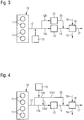
- Fig. 1 1 shows in highly schematic form an internal combustion engine 10 with a plurality of cylinders 11, wherein exhaust gas 12 leaving the internal combustion engine 10 is guided via an exhaust gas aftertreatment system downstream of the internal combustion engine 10, which comprises an SCR catalytic converter 13.
- the exhaust gas 12 leaving the internal combustion engine 10 is thus supplied to the SCR catalytic converter 13 as unpurified exhaust gas 12 and leaves the SCR catalytic converter 13 as at least partially purified exhaust gas 14.
- a reducing agent is used for exhaust gas purification, namely for denitrification of the exhaust gas 12 , needed, being as Reducing agent ammonia is used.
- the NH 3 precursors urea, carbamide, guanidium formate.
- the ammonia required for exhaust gas purification in the SCR catalytic converter 13 can be added to the unpurified exhaust gas 12 upstream of the SCR catalytic converter 13 by means of a device 15, either directly as ammonia or as ammonia precursor substance, which is then converted into ammonia in the exhaust gas.
- the device 15 is an ammonia generator.
- the device 15 is preferably a nozzle with the aid of which ammonia precursor substance, in particular urea, is injected into the exhaust gas 12.
- the urea is then vaporized in the exhaust gas 12 upstream of the SCR catalyst 13 to water vapor, carbon dioxide and ammonia.
- an exhaust gas scrubber 16 is positioned downstream of the SCR catalytic converter 13.
- ammonia which is contained in the exhaust gas 14 leaving the SCR catalytic converter 13, together with sulfur oxides, which are also contained in the exhaust gas 14 leaving the SCR catalytic converter 13, with the formation of ammonium salts from the exhaust gas washable.
- exhaust gas 17 Downstream of the exhaust gas scrubber 16 is therefore exhaust gas 17, which both Was subjected to a denitrification and desulfurization, from which therefore sulfur oxides and nitrogen oxides were removed.
- the exhaust gas scrubber 16 is supplied with the exhaust gas 14 leaving the SCR catalytic converter 13 and, on the other hand, with water as the so-called detergent 18, the exhaust gas scrubber leaving the desulfurized exhaust gas 17 on the one hand and waste water 19 enriched with ammonium salts on the other.
- the device 15 positioned upstream of the SCR catalytic converter 13 such that the same ammonia and / or an ammonia precursor substance is introduced into the exhaust gas in an amount greater than that in the SCR catalytic converter 13 is convertible amount of ammonia. Accordingly, downstream of the SCR catalyst 13 in the exhaust gas 14 ammonia in an amount that can be used in the exhaust gas scrubber 16 to wash out to desulfurize the exhaust gas 14 from the same sulfur oxides to form ammonium salts.
- the device 15 positioned upstream of the SCR catalyst 13 introduces the ammonia and / or the ammonia precursor substance into the exhaust gas 12 in an amount such that ammonia is contained in the exhaust gas 14 downstream of the SCR catalyst 13 in an amount such that the pH value of the waste water 19 of the exhaust gas scrubber 16 is between 4 and 8, preferably between 5 and 7, particularly preferably between 5.5 and 6.5.
- This can be established via a control circuit in which the pH value of the waste water 19 is measured, compared with a setpoint value and depending on this the device 15 is controlled by adjusting the amount of ammonia and / or the ammonia precursor substance introduced into the exhaust gas so that the measured pH approaches the setpoint of the same.
- an effective desulfurization and denitrification of exhaust gas in particular for a marine diesel engine operated with heavy oil is possible, with ammonia being used as fuel for denitrification as well as for desulfurization. Due to the increased amount of ammonia available for denitrification in the region of the SCR catalytic converter 13, a particularly effective denitrification of the exhaust gas is possible in the region of the SCR catalytic converter 13.
- the ammonia contained in the exhaust gas 14 downstream of the SCR catalytic converter 13 is used in the region of the exhaust gas scrubber 16 for the desulfurization of the exhaust gas.
- Fig. 2 shows a development of the embodiment of Fig. 1 , wherein the embodiment of the Fig. 2 from the embodiment of Fig. 1 only differs in that the exhaust aftertreatment system of Fig. 2 has a bypass 20.
- the bypass 20 upstream of the SCR catalyst 13 and downstream of the device 15, which serves to introduce the ammonia and / or ammonia precursor substance into the exhaust gas 12, the exhaust gas 12 with formation of a main exhaust stream 12a and a partial exhaust gas stream 12b exhaust branchable, the Exhaust main flow 12a is passed over the SCR catalyst 14, and wherein the partial exhaust gas stream 12b is passed over the bypass 20 on the SCR catalyst 13.
- the partial exhaust gas flow 12 b led past the same can be combined with the exhaust gas flow 14 leaving the SCR catalytic converter 13, in order then to be guided together via the exhaust gas scrubber 16.
- the denitration in the SCR catalyst 13 and the desulfurization in the scrubber 14 can be adjusted or controlled to some extent independently.
- Fig. 3 shows a development of the embodiment of Fig. 2 in which a further SCR catalytic converter 21 is positioned in the bypass 20 in order to also supply the partial exhaust gas flow 12b upstream of the exhaust scrubber 16 for denitrification over its own SCR catalyst 21 to lead.
- a further SCR catalytic converter 21 is positioned in the bypass 20 in order to also supply the partial exhaust gas flow 12b upstream of the exhaust scrubber 16 for denitrification over its own SCR catalyst 21 to lead.
- the denitrification of the exhaust gas can be improved.
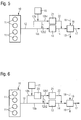
- FIG. 4 Another variant of the invention shows Fig. 4 , wherein also in the embodiment of Fig. 4 the exhaust aftertreatment system includes a bypass 22.
- the exhaust gas 12 in turn divided into a main exhaust stream 12a and a partial exhaust gas stream 12b, wherein the main exhaust stream 12a is forced over the SCR catalyst 13.
- the bypass 22 is assigned, so that the bypass 22, the exhaust gas upstream of the device 15 into the main exhaust stream 12a and the partial exhaust stream 12b divided.
- the device 15 introduces the ammonia and / or the ammonia precursor substance into the partial exhaust stream 12b, wherein the partial exhaust gas stream 12b is divided downstream into two parts 12b1 and 12b2 downstream of the device 15.
- the portion 12b1 of the exhaust gas substream 12b is bypassed the SCR catalyst 13 and mixed downstream of it and upstream of the exhaust scrubber 16 with the exhaust gas 14 exiting the SCR catalyst 13.
- the part 12b2 of the exhaust gas partial flow 12b is mixed with the exhaust main flow 12a upstream of the SCR catalyst 13, and passed along with the same via the SCR catalyst 13.
- Fig. 5 shows a development of the embodiment of Fig. 4 in which in accordance with the embodiment of the Fig. 3 also the bypass 22 a further SCR catalyst 21 is supplied, via which in the embodiment of the Fig. 5 the part 12b1 of the exhaust gas partial flow 12b is guided.
- Fig. 6 shows a development of the embodiment of Fig. 5 , in which the bypass 22 downstream of the device 15, in the embodiment of the Fig. 6 the metered addition of an ammonia precursor substance into the partial exhaust stream 12b, a hydrolysis catalyst 23 is assigned. Via the hydrolysis catalytic converter 23, the conversion of the ammonia precursor substance into ammonia in the partial exhaust gas stream 12 b can be improved or supported. The division of the partial exhaust gas stream 12 b into the two parts 12 b 1 and 12 b 2 takes place downstream of the hydrolysis catalytic converter 23.
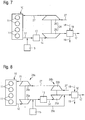
- FIGS. 7 and 8 show two embodiments of the invention, in which the variant of Fig. 1 is used in an exhaust-charged internal combustion engine.
- Fig. 7 an internal combustion engine 10 with a single-stage exhaust charging via a single exhaust gas turbocharger 24, wherein the exhaust gas turbocharger 24, a turbine 25 and a compressor 26 are shown.
- the SCR catalyst 13 together with the device 15, which serves to meter the ammonia and / or the ammonia precursor substance into the exhaust gas 12, is arranged upstream of the turbine 25 of the exhaust gas turbocharger 24, but the exhaust gas scrubber 16 is positioned downstream of the turbine 25 of the exhaust gas turbocharger 24.
- Fig. 8 shows a variant of an internal combustion engine 10 with a two-stage exhaust charging, which thus comprises two exhaust gas turbochargers 24a, 24b.
- the exhaust gas turbocharger 24a is a high-pressure exhaust gas turbocharger and the exhaust gas turbocharger 24b to a low-pressure exhaust gas turbocharger.
- the SCR catalyst 13 and the ammonia precursor substance introduction means 15 are arranged downstream of the high pressure turbine 25a of the high pressure turbocharger 24a and upstream of the low pressure turbine 25b of the low pressure turbocharger 24b, whereas the exhaust scrubber 16 downstream of the low pressure turbine 25b of the low pressure turbocharger 24b is arranged.
- Energy obtained in the exhaust-gas turbochargers 24a, 24b during the expansion of the exhaust gas in the region of the turbines 25a, 25b is used to two-stage charge air 27 to be supplied to the internal combustion engine 10, namely in the region of the low-pressure compressor 26b and of the high-pressure compressor 26a of low-pressure turbocharger 24b and high-pressure turbocharger 24a ,
- the ammonia or the ammonia precursor substance is introduced into the exhaust gas via the device 15 in such a way that a uniform ammonia concentration is set across the inlet cross section of the or each SCR catalytic converter 13 or 21.
- FIG. 9 a development of the embodiment of Fig. 1 in which 13 different ammonia concentrations are set over the inlet cross section of the SCR catalyst.
- two devices 15a, 15b shown each of the introduction of ammonia or an ammonia precursor substance upstream of the SCR catalyst 13 in which the internal combustion engine 10 leaving the exhaust gas 12 are used, in such a way that sets a different ammonia concentration over the inlet cross section of the SCR catalyst.
- This can be ensured, for example, by the fact that the two devices 15a, 15b contain the ammonia or the ammonia precursor substance with a different mass flow, as in FIG Fig. 9 shown, directly in the inlet region of the SCR catalyst 13 in the exhaust gas 12 bring.
- the setting of a different ammonia concentration over the inlet cross section of the SCR catalytic converter 13 preferably takes place such that a uniform distribution index of ammonia below 0.8, preferably below 0, downstream of the SCR catalytic converter 13 in the same leaving exhaust gas 14 and thus upstream of the exhaust scrubber 16 7, more preferably below 0.6.
- the denitrification in an SCR catalyst 13 and the desulfurization downstream thereof in a Exhaust scrubber 16 takes place.
- the SCR catalytic converter 13 is operated with excess ammonia, so that downstream of the SCR catalytic converter 13 and upstream of the exhaust scrubber 16 there is a defined amount of ammonia which can be used for desulfurization in the scrubber 16.
Landscapes
- Engineering & Computer Science (AREA)
- Chemical & Material Sciences (AREA)
- Chemical Kinetics & Catalysis (AREA)
- Combustion & Propulsion (AREA)
- Health & Medical Sciences (AREA)
- Environmental & Geological Engineering (AREA)
- Mechanical Engineering (AREA)
- General Engineering & Computer Science (AREA)
- General Chemical & Material Sciences (AREA)
- Biomedical Technology (AREA)
- Analytical Chemistry (AREA)
- Oil, Petroleum & Natural Gas (AREA)
- Toxicology (AREA)
- Ocean & Marine Engineering (AREA)
- Exhaust Gas After Treatment (AREA)
- Exhaust Gas Treatment By Means Of Catalyst (AREA)
- Supercharger (AREA)
- Treating Waste Gases (AREA)
Claims (6)
- Système de post-traitement pour un moteur à combustion interne, notamment pour un moteur à combustion interne diesel de navire fonctionnant au fioul lourd, avec un catalyseur SCR (13), qui utilise de l'ammoniaque comme moyen de réduction pour la dénitration du gaz d'échappement et comportant un dispositif (15, 15a, 15b) positionné en amont vu dans la direction d'écoulement du gaz d'échappement du catalyseur SCR (13), par l'intermédiaire duquel de l'ammoniaque et/ou un précurseur d'ammoniaque, qui est converti dans le gaz d'échappement en ammoniaque, peut être introduit dans le gaz d'échappement en amont du catalyseur SCR (13), dans lequel en aval du catalyseur SCR (13) un dispositif de lavage de gaz d'échappement (16) est positionné, par l'intermédiaire duquel une quantité d'ammoniaque définie appliquée en amont du catalyseur SCR (13), qui est contenue dans le gaz d'échappement quittant le catalyseur SCR (13), peut être lavée conjointement à des oxydes de soufre, qui sont également contenus dans le gaz d'échappement quittant le catalyseur SCR (13), en formant des sels d'ammonium à partir des gaz d'échappement, caractérisé en ce que une dérivation (20, 20a) est prévue, par l'intermédiaire de laquelle un courant partiel de gaz d'échappement (12b) en aval du dispositif (15, 15a, 16), qui sert à introduire l'ammoniaque et/ou le précurseur d'ammoniaque dans les gaz d'échappement, et en amont du catalyseur SCR (13) peut être dérivé des gaz d'échappement en formant un courant principal de gaz d'échappement (12a), qui peut être guidé par l'intermédiaire du catalyseur SCR (13), et peut ensuite être alimenté en aval du catalyseur SCR (13) et en amont du dispositif de lavage de gaz d'échappement (16) dans le gaz d'échappement (14) guidé à travers le catalyseur SCR, ou une dérivation (22) est prévue, par l'intermédiaire de laquelle un courant partiel de gaz d'échappement (12b) peut être dévié en amont du dispositif (15), qui sert à introduire l'ammoniaque et/ou le précurseur d'ammoniaque dans les gaz d'échappement, et en amont du catalyseur SCR (13), des gaz d'échappement en formant un courant principal de gaz d'échappement (12a), qui peut être guidé à travers le catalyseur SCR (13), dans lequel le dispositif (15, 15a, 15b), qui sert à introduire l'ammoniaque et/ou le précurseur d'ammoniaque dans les gaz d'échappement, est coordonné à la dérivation (22) et introduit l'ammoniaque et/ou le précurseur d'ammoniaque dans le courant partiel de gaz d'échappement (12b), et dans lequel une première partie (12b2)du courant partiel de gaz d'échappement (12b) en amont du catalyseur SCR (13) peut être alimentée dans le courant principal de gaz d'échappement et une deuxième partie (12b1) du courant partiel de gaz d'échappement (12b) en aval du catalyseur SCR (13) et en amont du dispositif de lavage des gaz d'échappement (16) peut être alimentée dans les gaz d'échappement (14) guidés à travers le catalyseur SCR.
- Système de post-traitement des gaz d'échappement selon la revendication 1, caractérisé en ce que le dispositif (15, 15a, 15b) positionné en amont du catalyseur SCR (13) introduit l'ammoniaque et/ou le précurseur d'ammoniaque dans les gaz d'échappement en une quantité, qui est plus grande que la quantité d'ammoniaque pouvant être convertie dans le catalyseur SCR (13), de sorte qu'en aval du catalyseur SCR de l'ammoniaque soit contenu dans une quantité, qui correspond à une valeur de pH des eaux usées du dispositif de lavage des gaz d'échappement (16) comprise entre 4 et 8.
- Système de post-traitement des gaz d'échappement selon la revendication 2, caractérisé en ce que le dispositif (15, 15a, 15b) introduit l'ammoniaque et/ou le précurseur d'ammoniaque dans les gaz d'échappement dans une quantité telle que la valeur de pH des eaux usées soit comprise entre 5 et 7, de préférence entre 5,5 et 6,5.
- Système de post-traitement des gaz d'échappement selon la revendication 1, caractérisé en ce que dans la dérivation (20, 20a, 20b) un catalyseur SCR supplémentaire (21) est disposé, par l'intermédiaire duquel le courant partiel de gaz d'échappement (12b) ou une partie (12b1) alimenté dans le gaz d'échappement (14) peut être guidé en aval du catalyseur SCR (13) et en amont du dispositif de lavage de gaz d'échappement (16).
- Système de post-traitement des gaz d'échappement selon une des revendications 1 à 4, caractérisé par une turbine (25, 25b) d'un turbocompresseur de gaz d'échappement, dans lequel le dispositif (15, 15a, 15b)pour introduire l'ammoniaque et/ou le précurseur d'ammoniaque dans les gaz d'échappement et de préférence également dans le catalyseur SCR (13) en amont de la turbine (25, 25b) du turbocompresseur de gaz d'échappement et dans le dispositif de lavage de gaz d'échappement (16) en aval de la turbine (25, 25b) du turbocompresseur de gaz d'échappement.
- Système de post-traitement des gaz d'échappement selon une des revendications 1, 4 ou 5, caractérisé en ce que la dérivation (20a) sert simultanément de limiteur de pression de suralimentation de turbocompresseur.
Applications Claiming Priority (2)
| Application Number | Priority Date | Filing Date | Title |
|---|---|---|---|
| DE102014007913.9A DE102014007913A1 (de) | 2014-05-27 | 2014-05-27 | Abgasnachbehandlungssystem und Verfahren zur Abgasnachbehandlung |
| PCT/EP2015/001037 WO2015180831A1 (fr) | 2014-05-27 | 2015-05-21 | Système de post-traitement des gaz d'échappement et procédé de post-traitement des gaz d'échappement |
Publications (2)
| Publication Number | Publication Date |
|---|---|
| EP3149298A1 EP3149298A1 (fr) | 2017-04-05 |
| EP3149298B1 true EP3149298B1 (fr) | 2018-07-04 |
Family
ID=53191638
Family Applications (1)
| Application Number | Title | Priority Date | Filing Date |
|---|---|---|---|
| EP15723650.6A Not-in-force EP3149298B1 (fr) | 2014-05-27 | 2015-05-21 | Système de post-traitement des gaz d'échappement et procédé de post-traitement des gaz d'échappement |
Country Status (8)
| Country | Link |
|---|---|
| US (1) | US10221740B2 (fr) |
| EP (1) | EP3149298B1 (fr) |
| JP (1) | JP6246385B2 (fr) |
| KR (1) | KR101822777B1 (fr) |
| CN (1) | CN106460612A (fr) |
| DE (1) | DE102014007913A1 (fr) |
| DK (1) | DK3149298T3 (fr) |
| WO (1) | WO2015180831A1 (fr) |
Cited By (2)
| Publication number | Priority date | Publication date | Assignee | Title |
|---|---|---|---|---|
| EP3670855A1 (fr) | 2018-12-19 | 2020-06-24 | Winterthur Gas & Diesel Ltd. | Système de post-traitement de gaz d'échappement |
| EP3670856A1 (fr) | 2018-12-19 | 2020-06-24 | Winterthur Gas & Diesel Ltd. | Système de post-traitement de gaz d'échappement |
Families Citing this family (17)
| Publication number | Priority date | Publication date | Assignee | Title |
|---|---|---|---|---|
| DE102015007908A1 (de) * | 2015-06-20 | 2016-12-22 | Man Truck & Bus Ag | Verfahren zum Betreiben eines Gasmotors |
| WO2017101965A1 (fr) * | 2015-12-14 | 2017-06-22 | Volvo Truck Corporation | Système de moteur à combustion interne et procédé pour moteur à combustion interne |
| DE102016205299A1 (de) * | 2016-03-31 | 2017-10-05 | Man Diesel & Turbo Se | Brennkraftmaschine mit Abgasnachbehandlungssystem |
| DE102017112731A1 (de) * | 2017-06-09 | 2018-12-13 | Man Diesel & Turbo Se | Verfahren und Steuergerät zum Betreiben eines SCR-Abgasnachbehandlungssystems einer Brennkraftmaschine |
| DE102017214448B4 (de) * | 2017-08-18 | 2022-10-06 | Vitesco Technologies GmbH | Verfahren zum Betreiben einer Abgasnachbehandlungsanlage eines einen Vor-Dreiwegekatalysator aufweisenden Verbrennungsmotors und Abgasnachbehandlungsanlage |
| GB2567205B (en) * | 2017-10-06 | 2021-06-23 | Siemens Plc | Uses of an absorbent, and methods and apparatuses relating thereto |
| KR102402334B1 (ko) * | 2017-12-15 | 2022-05-27 | 에이치에스디엔진 주식회사 | 선택적 촉매 환원 시스템 및 선박에 설치된 선택적 촉매 환원 시스템의 제어방법 |
| US11220943B2 (en) * | 2018-04-16 | 2022-01-11 | Volvo Truck Corporation | Internal combustion engine arrangement |
| KR102091171B1 (ko) * | 2018-08-08 | 2020-03-20 | 한국생산기술연구원 | 황산화물 및 질소산화물의 동시 저감이 가능한 가압 하이브리드 응축기 |
| JP7199192B2 (ja) | 2018-10-09 | 2023-01-05 | 株式会社ジャパンエンジンコーポレーション | 舶用scrシステム |
| DE102018128152A1 (de) * | 2018-11-12 | 2020-05-14 | Man Energy Solutions Se | Verfahren zur Nachbehandlung des Abgases einer Brennkraftmaschine und Brennkraftmaschine |
| KR102130491B1 (ko) * | 2019-03-13 | 2020-07-14 | 주식회사 냄새뚝 | 선박 배기가스 정화장치 및 방법 |
| DE102019209792A1 (de) * | 2019-07-03 | 2021-01-07 | Hyundai Motor Company | System und Verfahren zur Abgasnachbehandlung |
| EP4080022A1 (fr) * | 2021-04-20 | 2022-10-26 | Winterthur Gas & Diesel Ltd. | Procédé de post-traitement de gaz d'échappement |
| JP7661128B2 (ja) * | 2021-05-24 | 2025-04-14 | 三菱造船株式会社 | 船舶 |
| JP7808952B2 (ja) * | 2021-11-10 | 2026-01-30 | 三菱重工業株式会社 | 浮体 |
| KR102671339B1 (ko) * | 2022-09-14 | 2024-06-03 | 현대종합금속 주식회사 | 암모니아 공급 장치 |
Family Cites Families (19)
| Publication number | Priority date | Publication date | Assignee | Title |
|---|---|---|---|---|
| DE3601378A1 (de) | 1986-01-18 | 1987-07-23 | Degussa | Verfahren zur reinigung von oxide des stickstoffs und schwefels enthaltenden abgasen aus verbrennungsanlagen |
| DE3732191C1 (en) * | 1987-09-24 | 1989-04-06 | Steinmueller Gmbh L & C | Method for treating the heat exchanger impinged with an ammonium sulphate-containing gas on washing |
| US5164167A (en) | 1988-10-24 | 1992-11-17 | Regents Of The University Of California | Process for the removal of acid forming gases from exhaust gases |
| JPH04502121A (ja) * | 1989-10-19 | 1992-04-16 | ザ リージェンツ オブ ザ ユニバーシティ オブ カリフォルニア | 排気ガスからの酸生成ガスの除去方法 |
| NO904892L (no) * | 1990-11-12 | 1992-05-13 | Miljoeutvikling As | Apparat og framgangsmaate for rensing av eksos med hensyn til so2, nox og stoev. |
| JP2001187315A (ja) * | 1999-12-28 | 2001-07-10 | Mitsubishi Heavy Ind Ltd | 脱硝用のアンモニア注入装置 |
| JP2005125275A (ja) * | 2003-10-27 | 2005-05-19 | Babcock Hitachi Kk | ディーゼル排ガス処理装置および処理方法 |
| DE102004027593A1 (de) | 2004-06-05 | 2005-12-29 | Man B & W Diesel Ag | Motorenanlage mit Abgasturboaufladung und Betrieb eines SCR-Katalysators |
| US8230678B2 (en) * | 2007-06-21 | 2012-07-31 | Daimler Trucks North America Llc | Treatment of diesel engine exhaust |
| NO329851B1 (no) * | 2008-08-22 | 2011-01-10 | Sargas As | Fremgangsmate og anlegg for a rense eksos fra dieselmotorer |
| DE102008041530A1 (de) * | 2008-08-25 | 2010-03-04 | Dirk Dombrowski | Verfahren und Abgasanlage zur Reinigung SOx-haltiger Abgase, insbesondere von Schiffsbrennkraftmaschinen |
| US8096125B2 (en) | 2009-12-23 | 2012-01-17 | Ford Global Technologies, Llc | Methods and systems for emission system control |
| DE102010042419A1 (de) * | 2010-10-13 | 2012-04-19 | Wolfgang Bengel | Verfahren und Vorrichtung zur Reinigung von schwefelhaltigem Abgas aus schwerölgefeuerten Schiffsantrieben |
| JP6207498B2 (ja) | 2011-03-28 | 2017-10-04 | ハルドール・トプサー・アクチエゼルスカベット | 内燃機関からの排ガス中の窒素酸化物及び硫黄酸化物を還元する方法 |
| JP2012207608A (ja) * | 2011-03-30 | 2012-10-25 | Hitachi Zosen Corp | 排ガス浄化方法および装置 |
| CN102364068B (zh) * | 2011-06-28 | 2013-01-09 | 顾忠华 | 船用尾排气处理系统 |
| FI123737B (fi) * | 2012-02-13 | 2013-10-15 | Oy Langh Ship Ab | Menetelmä laivojen pakokaasuissa olevien epäpuhtauksien käsittelemiseksi, ja laiva, jossa pakokaasupesuri |
| DE102012017312A1 (de) * | 2012-09-03 | 2014-03-06 | Man Diesel & Turbo Se | Brennkraftmaschine |
| DE102013012399A1 (de) * | 2013-07-26 | 2015-01-29 | Man Diesel & Turbo Se | Verfahren zur Abgasnachbehandlung an einer Brennkraftmaschine und Brennkraftkraftmaschine |
-
2014
- 2014-05-27 DE DE102014007913.9A patent/DE102014007913A1/de not_active Withdrawn
-
2015
- 2015-05-21 KR KR1020167022167A patent/KR101822777B1/ko not_active Expired - Fee Related
- 2015-05-21 JP JP2016551151A patent/JP6246385B2/ja not_active Expired - Fee Related
- 2015-05-21 US US15/310,387 patent/US10221740B2/en not_active Expired - Fee Related
- 2015-05-21 WO PCT/EP2015/001037 patent/WO2015180831A1/fr not_active Ceased
- 2015-05-21 CN CN201580027697.4A patent/CN106460612A/zh active Pending
- 2015-05-21 DK DK15723650.6T patent/DK3149298T3/da active
- 2015-05-21 EP EP15723650.6A patent/EP3149298B1/fr not_active Not-in-force
Non-Patent Citations (1)
| Title |
|---|
| None * |
Cited By (2)
| Publication number | Priority date | Publication date | Assignee | Title |
|---|---|---|---|---|
| EP3670855A1 (fr) | 2018-12-19 | 2020-06-24 | Winterthur Gas & Diesel Ltd. | Système de post-traitement de gaz d'échappement |
| EP3670856A1 (fr) | 2018-12-19 | 2020-06-24 | Winterthur Gas & Diesel Ltd. | Système de post-traitement de gaz d'échappement |
Also Published As
| Publication number | Publication date |
|---|---|
| EP3149298A1 (fr) | 2017-04-05 |
| JP6246385B2 (ja) | 2017-12-13 |
| KR20160107319A (ko) | 2016-09-13 |
| CN106460612A (zh) | 2017-02-22 |
| WO2015180831A1 (fr) | 2015-12-03 |
| JP2017506716A (ja) | 2017-03-09 |
| US10221740B2 (en) | 2019-03-05 |
| KR101822777B1 (ko) | 2018-03-08 |
| US20170268399A1 (en) | 2017-09-21 |
| DK3149298T3 (da) | 2018-10-22 |
| DE102014007913A1 (de) | 2015-12-03 |
Similar Documents
| Publication | Publication Date | Title |
|---|---|---|
| EP3149298B1 (fr) | Système de post-traitement des gaz d'échappement et procédé de post-traitement des gaz d'échappement | |
| DE102013212801B4 (de) | Anordnung zur Abgasnachbehandlung für einen Verbrennungsmotor sowie Verfahren zum Betreiben eines Verbrennungsmotors | |
| EP1273338A1 (fr) | Dispositif et procédé pour la purification de gaz d'échappement avec un catalyseur d'accumulation des oxydes d'azote et un catalyseur SCR | |
| DE102009038835A1 (de) | Abgasreinigungsanlage für eine Brennkraftmaschine | |
| DE102013012399A1 (de) | Verfahren zur Abgasnachbehandlung an einer Brennkraftmaschine und Brennkraftkraftmaschine | |
| WO2019068851A1 (fr) | Procédé pour faire fonctionner un système de post-traitement des gaz d'échappement d'un moteur diesel et système de post-traitement des gaz d'échappement | |
| DE102015212485A1 (de) | Abgastrakt mit gegen eine Strömungsrichtung spritzende Dosiereinrichtung, Verfahren zum Betrieb eines Abgastraktes sowie Fahrzeug mit Abgastrakt | |
| DE102006038290A1 (de) | Abgasnachbehandlungssystem | |
| EP2811130B1 (fr) | Procédé et dispositif de désulfuration de reflux de gaz d'échappement | |
| DE102013221421A1 (de) | Verfahren und Vorrichtung zur Verminderung der Emission von Distickstoffmonoxid | |
| DE102013212802A1 (de) | Anordnung zur Abgasnachbehandlung für einen Verbrennungsmotorsowie Verfahren zum Betreiben eines Verbrennungsmotors | |
| DE102017218314B4 (de) | Verfahren zum Betreiben eines Dieselmotors und Dieselmotor mit Prüfung der NH3-Konzentration | |
| DE10361791A1 (de) | Vorrichtung zur Reinigung des Abgases einer Brennkraftmaschine und Verfahren zur Regeneration einer solchen Abgasreinigungsanlage | |
| DE102019116775A1 (de) | Verfahren zum Betrieb einer Abgasnachbehandlungseinrichtung, Steuereinheit für eine Brennkraftmaschine und Brennkraftmaschine | |
| DE102019211991B4 (de) | Otto-Motor mit im Abgasstrang angeordnetem SCR-Katalysator zur Ammoniak-Konvertierung | |
| DE102011050928B4 (de) | Abgasreinigungsanlage und abgasreinigungsverfahren | |
| DE102008002469A1 (de) | Verfahren und Vorrichtung zur Abgasreinigung | |
| DE102015221028B4 (de) | Verfahren zum Betrieb einer Abgasnachbehandlungsvorrichtung eines Kraftfahrzeugs | |
| DE102019116776A1 (de) | Verfahren zum Betrieb einer Abgasnachbehandlungseinrichtung, Steuereinheit für eine Brennkraftmaschine und Brennkraftmaschine | |
| DE102019116774A1 (de) | Verfahren zum Betrieb einer Abgasnachbehandlungseinrichtung, Steuereinheit für eine Brennkraftmaschine und Brennkraftmaschine | |
| DE102015200073B4 (de) | Abgasnachbehandlungsanordnung | |
| DE102016121509A1 (de) | Vorrichtung und Verfahren zur Abgasnachbehandlung eines Verbrennungsmotors | |
| CH706957A2 (de) | Brennkraftmaschine bei welcher die Entstickung und die Entschwefelung des Abgasstroms kombiniert erfolgt. | |
| DE102014201390A1 (de) | Abgasnachbehandlungsanordnung | |
| DE102016112363A1 (de) | Abgasnachbehandlungssystem |
Legal Events
| Date | Code | Title | Description |
|---|---|---|---|
| STAA | Information on the status of an ep patent application or granted ep patent |
Free format text: STATUS: THE INTERNATIONAL PUBLICATION HAS BEEN MADE |
|
| PUAI | Public reference made under article 153(3) epc to a published international application that has entered the european phase |
Free format text: ORIGINAL CODE: 0009012 |
|
| STAA | Information on the status of an ep patent application or granted ep patent |
Free format text: STATUS: REQUEST FOR EXAMINATION WAS MADE |
|
| 17P | Request for examination filed |
Effective date: 20160613 |
|
| AK | Designated contracting states |
Kind code of ref document: A1 Designated state(s): AL AT BE BG CH CY CZ DE DK EE ES FI FR GB GR HR HU IE IS IT LI LT LU LV MC MK MT NL NO PL PT RO RS SE SI SK SM TR |
|
| AX | Request for extension of the european patent |
Extension state: BA ME |
|
| DAV | Request for validation of the european patent (deleted) | ||
| DAX | Request for extension of the european patent (deleted) | ||
| GRAP | Despatch of communication of intention to grant a patent |
Free format text: ORIGINAL CODE: EPIDOSNIGR1 |
|
| STAA | Information on the status of an ep patent application or granted ep patent |
Free format text: STATUS: GRANT OF PATENT IS INTENDED |
|
| INTG | Intention to grant announced |
Effective date: 20180122 |
|
| GRAS | Grant fee paid |
Free format text: ORIGINAL CODE: EPIDOSNIGR3 |
|
| GRAA | (expected) grant |
Free format text: ORIGINAL CODE: 0009210 |
|
| STAA | Information on the status of an ep patent application or granted ep patent |
Free format text: STATUS: THE PATENT HAS BEEN GRANTED |
|
| AK | Designated contracting states |
Kind code of ref document: B1 Designated state(s): AL AT BE BG CH CY CZ DE DK EE ES FI FR GB GR HR HU IE IS IT LI LT LU LV MC MK MT NL NO PL PT RO RS SE SI SK SM TR |
|
| REG | Reference to a national code |
Ref country code: GB Ref legal event code: FG4D Free format text: NOT ENGLISH |
|
| REG | Reference to a national code |
Ref country code: CH Ref legal event code: EP |
|
| REG | Reference to a national code |
Ref country code: AT Ref legal event code: REF Ref document number: 1014741 Country of ref document: AT Kind code of ref document: T Effective date: 20180715 |
|
| REG | Reference to a national code |
Ref country code: IE Ref legal event code: FG4D Free format text: LANGUAGE OF EP DOCUMENT: GERMAN |
|
| REG | Reference to a national code |
Ref country code: DE Ref legal event code: R096 Ref document number: 502015004939 Country of ref document: DE |
|
| REG | Reference to a national code |
Ref country code: DK Ref legal event code: T3 Effective date: 20181015 |
|
| REG | Reference to a national code |
Ref country code: NL Ref legal event code: MP Effective date: 20180704 |
|
| REG | Reference to a national code |
Ref country code: LT Ref legal event code: MG4D |
|
| RAP2 | Party data changed (patent owner data changed or rights of a patent transferred) |
Owner name: MAN ENERGY SOLUTIONS SE |
|
| PG25 | Lapsed in a contracting state [announced via postgrant information from national office to epo] |
Ref country code: NL Free format text: LAPSE BECAUSE OF FAILURE TO SUBMIT A TRANSLATION OF THE DESCRIPTION OR TO PAY THE FEE WITHIN THE PRESCRIBED TIME-LIMIT Effective date: 20180704 |
|
| PG25 | Lapsed in a contracting state [announced via postgrant information from national office to epo] |
Ref country code: RS Free format text: LAPSE BECAUSE OF FAILURE TO SUBMIT A TRANSLATION OF THE DESCRIPTION OR TO PAY THE FEE WITHIN THE PRESCRIBED TIME-LIMIT Effective date: 20180704 Ref country code: GR Free format text: LAPSE BECAUSE OF FAILURE TO SUBMIT A TRANSLATION OF THE DESCRIPTION OR TO PAY THE FEE WITHIN THE PRESCRIBED TIME-LIMIT Effective date: 20181005 Ref country code: IS Free format text: LAPSE BECAUSE OF FAILURE TO SUBMIT A TRANSLATION OF THE DESCRIPTION OR TO PAY THE FEE WITHIN THE PRESCRIBED TIME-LIMIT Effective date: 20181104 Ref country code: NO Free format text: LAPSE BECAUSE OF FAILURE TO SUBMIT A TRANSLATION OF THE DESCRIPTION OR TO PAY THE FEE WITHIN THE PRESCRIBED TIME-LIMIT Effective date: 20181004 Ref country code: CZ Free format text: LAPSE BECAUSE OF FAILURE TO SUBMIT A TRANSLATION OF THE DESCRIPTION OR TO PAY THE FEE WITHIN THE PRESCRIBED TIME-LIMIT Effective date: 20180704 Ref country code: LT Free format text: LAPSE BECAUSE OF FAILURE TO SUBMIT A TRANSLATION OF THE DESCRIPTION OR TO PAY THE FEE WITHIN THE PRESCRIBED TIME-LIMIT Effective date: 20180704 Ref country code: PL Free format text: LAPSE BECAUSE OF FAILURE TO SUBMIT A TRANSLATION OF THE DESCRIPTION OR TO PAY THE FEE WITHIN THE PRESCRIBED TIME-LIMIT Effective date: 20180704 Ref country code: SE Free format text: LAPSE BECAUSE OF FAILURE TO SUBMIT A TRANSLATION OF THE DESCRIPTION OR TO PAY THE FEE WITHIN THE PRESCRIBED TIME-LIMIT Effective date: 20180704 Ref country code: BG Free format text: LAPSE BECAUSE OF FAILURE TO SUBMIT A TRANSLATION OF THE DESCRIPTION OR TO PAY THE FEE WITHIN THE PRESCRIBED TIME-LIMIT Effective date: 20181004 |
|
| PG25 | Lapsed in a contracting state [announced via postgrant information from national office to epo] |
Ref country code: AL Free format text: LAPSE BECAUSE OF FAILURE TO SUBMIT A TRANSLATION OF THE DESCRIPTION OR TO PAY THE FEE WITHIN THE PRESCRIBED TIME-LIMIT Effective date: 20180704 Ref country code: ES Free format text: LAPSE BECAUSE OF FAILURE TO SUBMIT A TRANSLATION OF THE DESCRIPTION OR TO PAY THE FEE WITHIN THE PRESCRIBED TIME-LIMIT Effective date: 20180704 Ref country code: HR Free format text: LAPSE BECAUSE OF FAILURE TO SUBMIT A TRANSLATION OF THE DESCRIPTION OR TO PAY THE FEE WITHIN THE PRESCRIBED TIME-LIMIT Effective date: 20180704 Ref country code: LV Free format text: LAPSE BECAUSE OF FAILURE TO SUBMIT A TRANSLATION OF THE DESCRIPTION OR TO PAY THE FEE WITHIN THE PRESCRIBED TIME-LIMIT Effective date: 20180704 |
|
| REG | Reference to a national code |
Ref country code: DE Ref legal event code: R081 Ref document number: 502015004939 Country of ref document: DE Owner name: DOERING, ANDREAS, DE Free format text: FORMER OWNER: MAN DIESEL & TURBO SE, 86153 AUGSBURG, DE Ref country code: DE Ref legal event code: R081 Ref document number: 502015004939 Country of ref document: DE Owner name: MAN ENERGY SOLUTIONS SE, DE Free format text: FORMER OWNER: MAN DIESEL & TURBO SE, 86153 AUGSBURG, DE |
|
| REG | Reference to a national code |
Ref country code: DE Ref legal event code: R097 Ref document number: 502015004939 Country of ref document: DE |
|
| PG25 | Lapsed in a contracting state [announced via postgrant information from national office to epo] |
Ref country code: EE Free format text: LAPSE BECAUSE OF FAILURE TO SUBMIT A TRANSLATION OF THE DESCRIPTION OR TO PAY THE FEE WITHIN THE PRESCRIBED TIME-LIMIT Effective date: 20180704 Ref country code: RO Free format text: LAPSE BECAUSE OF FAILURE TO SUBMIT A TRANSLATION OF THE DESCRIPTION OR TO PAY THE FEE WITHIN THE PRESCRIBED TIME-LIMIT Effective date: 20180704 |
|
| PLBE | No opposition filed within time limit |
Free format text: ORIGINAL CODE: 0009261 |
|
| STAA | Information on the status of an ep patent application or granted ep patent |
Free format text: STATUS: NO OPPOSITION FILED WITHIN TIME LIMIT |
|
| PG25 | Lapsed in a contracting state [announced via postgrant information from national office to epo] |
Ref country code: SM Free format text: LAPSE BECAUSE OF FAILURE TO SUBMIT A TRANSLATION OF THE DESCRIPTION OR TO PAY THE FEE WITHIN THE PRESCRIBED TIME-LIMIT Effective date: 20180704 Ref country code: SK Free format text: LAPSE BECAUSE OF FAILURE TO SUBMIT A TRANSLATION OF THE DESCRIPTION OR TO PAY THE FEE WITHIN THE PRESCRIBED TIME-LIMIT Effective date: 20180704 |
|
| 26N | No opposition filed |
Effective date: 20190405 |
|
| PG25 | Lapsed in a contracting state [announced via postgrant information from national office to epo] |
Ref country code: SI Free format text: LAPSE BECAUSE OF FAILURE TO SUBMIT A TRANSLATION OF THE DESCRIPTION OR TO PAY THE FEE WITHIN THE PRESCRIBED TIME-LIMIT Effective date: 20180704 |
|
| REG | Reference to a national code |
Ref country code: CH Ref legal event code: PL |
|
| GBPC | Gb: european patent ceased through non-payment of renewal fee |
Effective date: 20190521 |
|
| PG25 | Lapsed in a contracting state [announced via postgrant information from national office to epo] |
Ref country code: MC Free format text: LAPSE BECAUSE OF FAILURE TO SUBMIT A TRANSLATION OF THE DESCRIPTION OR TO PAY THE FEE WITHIN THE PRESCRIBED TIME-LIMIT Effective date: 20180704 Ref country code: CH Free format text: LAPSE BECAUSE OF NON-PAYMENT OF DUE FEES Effective date: 20190531 Ref country code: LI Free format text: LAPSE BECAUSE OF NON-PAYMENT OF DUE FEES Effective date: 20190531 |
|
| REG | Reference to a national code |
Ref country code: BE Ref legal event code: MM Effective date: 20190531 |
|
| PG25 | Lapsed in a contracting state [announced via postgrant information from national office to epo] |
Ref country code: LU Free format text: LAPSE BECAUSE OF NON-PAYMENT OF DUE FEES Effective date: 20190521 |
|
| PG25 | Lapsed in a contracting state [announced via postgrant information from national office to epo] |
Ref country code: TR Free format text: LAPSE BECAUSE OF FAILURE TO SUBMIT A TRANSLATION OF THE DESCRIPTION OR TO PAY THE FEE WITHIN THE PRESCRIBED TIME-LIMIT Effective date: 20180704 |
|
| PG25 | Lapsed in a contracting state [announced via postgrant information from national office to epo] |
Ref country code: GB Free format text: LAPSE BECAUSE OF NON-PAYMENT OF DUE FEES Effective date: 20190521 Ref country code: IE Free format text: LAPSE BECAUSE OF NON-PAYMENT OF DUE FEES Effective date: 20190521 |
|
| PG25 | Lapsed in a contracting state [announced via postgrant information from national office to epo] |
Ref country code: BE Free format text: LAPSE BECAUSE OF NON-PAYMENT OF DUE FEES Effective date: 20190531 |
|
| PG25 | Lapsed in a contracting state [announced via postgrant information from national office to epo] |
Ref country code: FR Free format text: LAPSE BECAUSE OF NON-PAYMENT OF DUE FEES Effective date: 20190531 Ref country code: PT Free format text: LAPSE BECAUSE OF FAILURE TO SUBMIT A TRANSLATION OF THE DESCRIPTION OR TO PAY THE FEE WITHIN THE PRESCRIBED TIME-LIMIT Effective date: 20181104 |
|
| PGFP | Annual fee paid to national office [announced via postgrant information from national office to epo] |
Ref country code: FI Payment date: 20200522 Year of fee payment: 6 Ref country code: DK Payment date: 20200527 Year of fee payment: 6 Ref country code: DE Payment date: 20200520 Year of fee payment: 6 |
|
| PG25 | Lapsed in a contracting state [announced via postgrant information from national office to epo] |
Ref country code: CY Free format text: LAPSE BECAUSE OF FAILURE TO SUBMIT A TRANSLATION OF THE DESCRIPTION OR TO PAY THE FEE WITHIN THE PRESCRIBED TIME-LIMIT Effective date: 20180704 |
|
| REG | Reference to a national code |
Ref country code: AT Ref legal event code: MM01 Ref document number: 1014741 Country of ref document: AT Kind code of ref document: T Effective date: 20200521 |
|
| PG25 | Lapsed in a contracting state [announced via postgrant information from national office to epo] |
Ref country code: HU Free format text: LAPSE BECAUSE OF FAILURE TO SUBMIT A TRANSLATION OF THE DESCRIPTION OR TO PAY THE FEE WITHIN THE PRESCRIBED TIME-LIMIT; INVALID AB INITIO Effective date: 20150521 Ref country code: MT Free format text: LAPSE BECAUSE OF FAILURE TO SUBMIT A TRANSLATION OF THE DESCRIPTION OR TO PAY THE FEE WITHIN THE PRESCRIBED TIME-LIMIT Effective date: 20180704 |
|
| REG | Reference to a national code |
Ref country code: DE Ref legal event code: R081 Ref document number: 502015004939 Country of ref document: DE Owner name: DOERING, ANDREAS, DE Free format text: FORMER OWNER: MAN ENERGY SOLUTIONS SE, 86153 AUGSBURG, DE |
|
| PG25 | Lapsed in a contracting state [announced via postgrant information from national office to epo] |
Ref country code: AT Free format text: LAPSE BECAUSE OF NON-PAYMENT OF DUE FEES Effective date: 20200521 |
|
| PGFP | Annual fee paid to national office [announced via postgrant information from national office to epo] |
Ref country code: IT Payment date: 20210726 Year of fee payment: 7 |
|
| REG | Reference to a national code |
Ref country code: DE Ref legal event code: R119 Ref document number: 502015004939 Country of ref document: DE |
|
| REG | Reference to a national code |
Ref country code: FI Ref legal event code: MAE |
|
| REG | Reference to a national code |
Ref country code: DK Ref legal event code: EBP Effective date: 20210531 |
|
| PG25 | Lapsed in a contracting state [announced via postgrant information from national office to epo] |
Ref country code: FI Free format text: LAPSE BECAUSE OF NON-PAYMENT OF DUE FEES Effective date: 20210521 |
|
| PG25 | Lapsed in a contracting state [announced via postgrant information from national office to epo] |
Ref country code: DK Free format text: LAPSE BECAUSE OF NON-PAYMENT OF DUE FEES Effective date: 20210531 Ref country code: DE Free format text: LAPSE BECAUSE OF NON-PAYMENT OF DUE FEES Effective date: 20211201 |
|
| PG25 | Lapsed in a contracting state [announced via postgrant information from national office to epo] |
Ref country code: MK Free format text: LAPSE BECAUSE OF FAILURE TO SUBMIT A TRANSLATION OF THE DESCRIPTION OR TO PAY THE FEE WITHIN THE PRESCRIBED TIME-LIMIT Effective date: 20180704 |
|
| PG25 | Lapsed in a contracting state [announced via postgrant information from national office to epo] |
Ref country code: IT Free format text: LAPSE BECAUSE OF NON-PAYMENT OF DUE FEES Effective date: 20220521 |