EP3149385B1 - Indicateur de bouchon à air détectant l'humidité pour défaillance de réservoir d'expansion - Google Patents
Indicateur de bouchon à air détectant l'humidité pour défaillance de réservoir d'expansion Download PDFInfo
- Publication number
- EP3149385B1 EP3149385B1 EP15800263.4A EP15800263A EP3149385B1 EP 3149385 B1 EP3149385 B1 EP 3149385B1 EP 15800263 A EP15800263 A EP 15800263A EP 3149385 B1 EP3149385 B1 EP 3149385B1
- Authority
- EP
- European Patent Office
- Prior art keywords
- color
- moisture
- indicator
- pressurized gas
- insert
- Prior art date
- Legal status (The legal status is an assumption and is not a legal conclusion. Google has not performed a legal analysis and makes no representation as to the accuracy of the status listed.)
- Active
Links
Images



Classifications
-
- F—MECHANICAL ENGINEERING; LIGHTING; HEATING; WEAPONS; BLASTING
- F24—HEATING; RANGES; VENTILATING
- F24D—DOMESTIC- OR SPACE-HEATING SYSTEMS, e.g. CENTRAL HEATING SYSTEMS; DOMESTIC HOT-WATER SUPPLY SYSTEMS; ELEMENTS OR COMPONENTS THEREFOR
- F24D3/00—Hot-water central heating systems
- F24D3/10—Feed-line arrangements, e.g. providing for heat-accumulator tanks, expansion tanks ; Hydraulic components of a central heating system
- F24D3/1008—Feed-line arrangements, e.g. providing for heat-accumulator tanks, expansion tanks ; Hydraulic components of a central heating system expansion tanks
-
- F—MECHANICAL ENGINEERING; LIGHTING; HEATING; WEAPONS; BLASTING
- F15—FLUID-PRESSURE ACTUATORS; HYDRAULICS OR PNEUMATICS IN GENERAL
- F15B—SYSTEMS ACTING BY MEANS OF FLUIDS IN GENERAL; FLUID-PRESSURE ACTUATORS, e.g. SERVOMOTORS; DETAILS OF FLUID-PRESSURE SYSTEMS, NOT OTHERWISE PROVIDED FOR
- F15B1/00—Installations or systems with accumulators; Supply reservoir or sump assemblies
- F15B1/02—Installations or systems with accumulators
- F15B1/04—Accumulators
- F15B1/08—Accumulators using a gas cushion; Gas charging devices; Indicators or floats therefor
- F15B1/10—Accumulators using a gas cushion; Gas charging devices; Indicators or floats therefor with flexible separating means
-
- F—MECHANICAL ENGINEERING; LIGHTING; HEATING; WEAPONS; BLASTING
- F15—FLUID-PRESSURE ACTUATORS; HYDRAULICS OR PNEUMATICS IN GENERAL
- F15B—SYSTEMS ACTING BY MEANS OF FLUIDS IN GENERAL; FLUID-PRESSURE ACTUATORS, e.g. SERVOMOTORS; DETAILS OF FLUID-PRESSURE SYSTEMS, NOT OTHERWISE PROVIDED FOR
- F15B1/00—Installations or systems with accumulators; Supply reservoir or sump assemblies
- F15B1/02—Installations or systems with accumulators
- F15B1/04—Accumulators
- F15B1/08—Accumulators using a gas cushion; Gas charging devices; Indicators or floats therefor
- F15B1/10—Accumulators using a gas cushion; Gas charging devices; Indicators or floats therefor with flexible separating means
- F15B1/12—Accumulators using a gas cushion; Gas charging devices; Indicators or floats therefor with flexible separating means attached at their periphery
- F15B1/14—Accumulators using a gas cushion; Gas charging devices; Indicators or floats therefor with flexible separating means attached at their periphery by means of a rigid annular supporting member
-
- F—MECHANICAL ENGINEERING; LIGHTING; HEATING; WEAPONS; BLASTING
- F15—FLUID-PRESSURE ACTUATORS; HYDRAULICS OR PNEUMATICS IN GENERAL
- F15B—SYSTEMS ACTING BY MEANS OF FLUIDS IN GENERAL; FLUID-PRESSURE ACTUATORS, e.g. SERVOMOTORS; DETAILS OF FLUID-PRESSURE SYSTEMS, NOT OTHERWISE PROVIDED FOR
- F15B20/00—Safety arrangements for fluid actuator systems; Applications of safety devices in fluid actuator systems; Emergency measures for fluid actuator systems
- F15B20/005—Leakage; Spillage; Hose burst
-
- F—MECHANICAL ENGINEERING; LIGHTING; HEATING; WEAPONS; BLASTING
- F16—ENGINEERING ELEMENTS AND UNITS; GENERAL MEASURES FOR PRODUCING AND MAINTAINING EFFECTIVE FUNCTIONING OF MACHINES OR INSTALLATIONS; THERMAL INSULATION IN GENERAL
- F16J—PISTONS; CYLINDERS; SEALINGS
- F16J3/00—Diaphragms; Bellows; Bellows pistons
- F16J3/02—Diaphragms
-
- F—MECHANICAL ENGINEERING; LIGHTING; HEATING; WEAPONS; BLASTING
- F16—ENGINEERING ELEMENTS AND UNITS; GENERAL MEASURES FOR PRODUCING AND MAINTAINING EFFECTIVE FUNCTIONING OF MACHINES OR INSTALLATIONS; THERMAL INSULATION IN GENERAL
- F16L—PIPES; JOINTS OR FITTINGS FOR PIPES; SUPPORTS FOR PIPES, CABLES OR PROTECTIVE TUBING; MEANS FOR THERMAL INSULATION IN GENERAL
- F16L55/00—Devices or appurtenances for use in, or in connection with, pipes or pipe systems
- F16L55/04—Devices damping pulsations or vibrations in fluids
- F16L55/045—Devices damping pulsations or vibrations in fluids specially adapted to prevent or minimise the effects of water hammer
- F16L55/05—Buffers therefor
- F16L55/052—Pneumatic reservoirs
- F16L55/053—Pneumatic reservoirs the gas in the reservoir being separated from the fluid in the pipe
-
- F—MECHANICAL ENGINEERING; LIGHTING; HEATING; WEAPONS; BLASTING
- F24—HEATING; RANGES; VENTILATING
- F24D—DOMESTIC- OR SPACE-HEATING SYSTEMS, e.g. CENTRAL HEATING SYSTEMS; DOMESTIC HOT-WATER SUPPLY SYSTEMS; ELEMENTS OR COMPONENTS THEREFOR
- F24D3/00—Hot-water central heating systems
- F24D3/10—Feed-line arrangements, e.g. providing for heat-accumulator tanks, expansion tanks ; Hydraulic components of a central heating system
- F24D3/1008—Feed-line arrangements, e.g. providing for heat-accumulator tanks, expansion tanks ; Hydraulic components of a central heating system expansion tanks
- F24D3/1016—Tanks having a bladder
-
- G—PHYSICS
- G01—MEASURING; TESTING
- G01M—TESTING STATIC OR DYNAMIC BALANCE OF MACHINES OR STRUCTURES; TESTING OF STRUCTURES OR APPARATUS, NOT OTHERWISE PROVIDED FOR
- G01M3/00—Investigating fluid-tightness of structures
-
- G—PHYSICS
- G01—MEASURING; TESTING
- G01M—TESTING STATIC OR DYNAMIC BALANCE OF MACHINES OR STRUCTURES; TESTING OF STRUCTURES OR APPARATUS, NOT OTHERWISE PROVIDED FOR
- G01M3/00—Investigating fluid-tightness of structures
- G01M3/02—Investigating fluid-tightness of structures by using fluid or vacuum
- G01M3/04—Investigating fluid-tightness of structures by using fluid or vacuum by detecting the presence of fluid at the leakage point
- G01M3/042—Investigating fluid-tightness of structures by using fluid or vacuum by detecting the presence of fluid at the leakage point by using materials which expand, contract, disintegrate, or decompose in contact with a fluid
-
- F—MECHANICAL ENGINEERING; LIGHTING; HEATING; WEAPONS; BLASTING
- F15—FLUID-PRESSURE ACTUATORS; HYDRAULICS OR PNEUMATICS IN GENERAL
- F15B—SYSTEMS ACTING BY MEANS OF FLUIDS IN GENERAL; FLUID-PRESSURE ACTUATORS, e.g. SERVOMOTORS; DETAILS OF FLUID-PRESSURE SYSTEMS, NOT OTHERWISE PROVIDED FOR
- F15B2201/00—Accumulators
- F15B2201/20—Accumulator cushioning means
- F15B2201/205—Accumulator cushioning means using gas
-
- F—MECHANICAL ENGINEERING; LIGHTING; HEATING; WEAPONS; BLASTING
- F15—FLUID-PRESSURE ACTUATORS; HYDRAULICS OR PNEUMATICS IN GENERAL
- F15B—SYSTEMS ACTING BY MEANS OF FLUIDS IN GENERAL; FLUID-PRESSURE ACTUATORS, e.g. SERVOMOTORS; DETAILS OF FLUID-PRESSURE SYSTEMS, NOT OTHERWISE PROVIDED FOR
- F15B2201/00—Accumulators
- F15B2201/30—Accumulator separating means
- F15B2201/315—Accumulator separating means having flexible separating means
- F15B2201/3151—Accumulator separating means having flexible separating means the flexible separating means being diaphragms or membranes
-
- F—MECHANICAL ENGINEERING; LIGHTING; HEATING; WEAPONS; BLASTING
- F15—FLUID-PRESSURE ACTUATORS; HYDRAULICS OR PNEUMATICS IN GENERAL
- F15B—SYSTEMS ACTING BY MEANS OF FLUIDS IN GENERAL; FLUID-PRESSURE ACTUATORS, e.g. SERVOMOTORS; DETAILS OF FLUID-PRESSURE SYSTEMS, NOT OTHERWISE PROVIDED FOR
- F15B2201/00—Accumulators
- F15B2201/50—Monitoring, detection and testing means for accumulators
-
- F—MECHANICAL ENGINEERING; LIGHTING; HEATING; WEAPONS; BLASTING
- F16—ENGINEERING ELEMENTS AND UNITS; GENERAL MEASURES FOR PRODUCING AND MAINTAINING EFFECTIVE FUNCTIONING OF MACHINES OR INSTALLATIONS; THERMAL INSULATION IN GENERAL
- F16L—PIPES; JOINTS OR FITTINGS FOR PIPES; SUPPORTS FOR PIPES, CABLES OR PROTECTIVE TUBING; MEANS FOR THERMAL INSULATION IN GENERAL
- F16L2201/00—Special arrangements for pipe couplings
- F16L2201/30—Detecting leaks
Definitions
- the present invention generally relates to expansion tanks, and, more particularly, to diaphragm expansion tanks having an indicator to alert a user if moisture is present in the gas side of the expansion tank.
- Expansion tanks are commonly used in heating, cooling and air condition systems to avoid unacceptable increase of system pressures during heat-up, generally by absorbing expanding fluid and limiting pressure within the system. Expansion tank designs include open tanks, closed compression tanks and diaphragm tanks.
- a diaphragm or bladder In a diaphragm expansion tank, a diaphragm or bladder is used to separate air from water within the tank.
- one side of the tank is connected to piping of a heating system (or cooling/air condition system) and therefore contains the water, while the other side contains air under pressure.
- a Schrader valve is typically provided at the air side of the tank for checking pressure and adding air, which allows the pressure of the tank to be adjusted as needed.
- An air/gas charge pressure on one side keeps the diaphragm at a distance away from the inside wall of the tank in the gas side.
- the water system pressure pushes back against the diaphragm, compressing the gas.
- the tank pressure is at an initial/pre-charge pressure. As the temperature in the system increases, the water expands to compress the gas chamber via the diaphragm, causing an increase in the gas and water system pressure.
- the diaphragm has a limited life. If eventually the diaphragm "bottoms out” on the tank wall, the tank becomes ineffective in the function it has been design to provide.
- Various failure modes for expansion tanks include incorrect precharge pressure (e.g. a low air precharge), excessive system pressure, diaphragm failure resulting in leak of air charge, and installation of an incorrectly sized tank (e.g. undersized tank which causes the diaphragm to overwork), all of which can lead to quick cycling and ultimately failure.
- the diaphragm can develop a pinhole, an abrasion, a cut or the like that allows water to enter the gas side of the tank. Over time, the gas will be absorbed into the water system and the gas charge will decrease to zero. At this point, the tank is considered ineffective. This can eventually cause failure of other equipment in the system or failure of the tank itself, resulting in water leakage into space surrounding the tank.
- test device for determining defects of pressure compensation tanks.
- the test device includes an indicator for pressure and/or moisture.
- US 2008/034763 A1 further shows a moisture indicator for refrigeration devices.
- the present invention provides an expansion tank which includes a housing that has an upper end wall, a side wall, and a lower end wall that together define a cavity.
- a flexible diaphragm extends within the cavity so as to separate the cavity into an upper portion, which is sealed to contain a pressurized gas, and a lower portion, which is sealed to contain a pressurized fluid.
- An indicator is positioned at the upper wall of the housing so as to visually alert a user if moisture is present in the pressurized gas side of the expansion tank.
- the indicator is in the form of an air cap indicator which is positioned in an upper end wall of the tank and in communication with the pressurized gas side of the tank.
- the indicator comprises an insert that displays a first color.
- the indicator displays a second color
- the predetermined level of moisture is a trace amount of moisture, and in some embodiments, the predetermined level of moisture is such that water droplets form and even a water volume exists.
- the predetermined level of moisture is a level at which material (e.g., steel) forming the pressurized gas side of the tank will corrode and rust.
- the indicator further comprises a cap at an upper portion, the insert at least partially disposed within the cap, and sidewalls extending downward from the cap to the upper end wall of the housing, wherein a gas tight and fluid tight seal is formed between the indicator and the upper end wall of the housing.
- at least a portion of the cap is fabricated of a transparent material through which the insert is visible.
- At least a portion of the cap can be fabricated of an optically magnifying material, such that the cap insert is viewable and magnified therethrough.
- the cap is provided with a first color, and when the pressurized gas side of the tank is contacted with the predetermined level of moisture or greater, the material forming the pressurized gas side corrodes and rusts. This corrosion and rust will then deposit residue onto the surface of the cap.
- the cap is provided with a first color, and at least a portion of the indicator is fabricated of a material that is hydrochromic such that the first color will change to the second color when contacted with the predetermined level of moisture or greater.
- this first color is a light color that will contrast with the second color and with rust, which is typically red-orange-brown-color.
- the cap is a bright white color, which provides a sharp contrast with deposited rust.
- the bright white, or other color, of the cap can be provided either by the material itself forming the cap (e.g. using a white plastic material that is formed into the cap) or by coloring the cap with the desired bright white or other color.
- At least a portion of the insert is coated with a hydrochromic ink.
- the hydrochromic ink displays the first color.
- the hydrochromic ink becomes clear when contacted with the predetermined level of moisture or greater and therefore the second color is displayed.
- the insert is of the first color.
- rust deposits form on the first color to indicate a second color.
- water droplets or even a water volume can be seen through the clear portion of the cap where the insert if visible.
- the indicator is disposed to enclose a valve on the upper end wall of the housing, the valve being in communication with the pressurized gas in the upper portion of the cavity.
- a method for indicating a failure in an expansion tank comprising a flexible diaphragm, where the flexible diaphragm divides the tank into a pressurized gas side and a pressurized fluid side.
- An indicator is positioned in an upper end wall of the expansion tank and in fluid communication with the pressurized gas side, e.g. via a valve.
- the indicator includes a cap having a cap insert disposed therein.
- the cap has a domed portion ("cap dome"), at least a portion of which is clear so that a user can view the contents therein.
- the cap insert is designed so as to display a first color when the pressurized gas side of the tank is at its normal operating condition, and to display a second color when exposed to a predetermined level of moisture or greater
- the valve is actuated to allow pressurized gas from the pressurized gas side of the tank to enter the cap dome and come into contact with the cap insert. If the pressurized gas side of the tank has been exposed to or contains a detectable level of moisture, then the cap displays the second color to indicate either problems with or failure of the expansion tank. If the pressurized gas side of the tank has not been exposed to or does not contain a detectable level of moisture, then the cap insert will display the first color to indicate that the expansion tank is operating properly.
- the predetermined level of moisture is a trace amount of moisture, in some embodiments, the predetermined level of moisture such that water droplets form and even a water volume exists , and in yet other embodiments, the predetermined level of moisture is a level at which material (e.g., steel) forming the pressurized gas side of the tank will corrode and rust.
- material e.g., steel
- the terms "comprises,” “comprising,” “containing,” “having” and the like can have the meaning ascribed to them in U.S. Patent law and can mean “includes,” “including,” and the like; “consisting essentially of' or “consists essentially” likewise has the meaning ascribed in U.S. Patent law and the term is open-ended, allowing for the presence of more than that which is recited so long as basic or novel characteristics of that which is recited is not changed by the presence of more than that which is recited, but excludes prior art embodiments.
- an "excessive" amount of moisture means any moisture present in the pressurized gas side of the tank as a result of a compromised diaphragm.
- a "predetermined level of moisture or greater” is one which causes the cap to change from one color to another color, such as by causing a hydrochromic ink to change color, or by causing a material (e.g., steel) forming the pressurized gas side of the tank to corrode and rust or by allowing water droplets or a water volume to be present.
- a predetermined level can include in some embodiments a trace amount of moisture, or in other embodiments any amount of moisture such that water droplets form and even a water volume exists
- the term "about” is understood as within a range of normal tolerance in the art, for example within 2 standard deviations of the mean. About can be understood as within 10%, 9%, 8%, 7%, 6%, 5%, 4%, 3%, 2%, 1%, 0.5%, 0.1%, 0.05%, or 0.01% of the stated value. Unless otherwise clear from context, all numerical values provided herein are modified by the term about.
- Ranges provided herein are understood to be shorthand for all of the values within the range.
- a range of 1 to 50 is understood to include any number, combination of numbers, or sub-range from the group consisting 1, 2, 3, 4, 5, 6, 7, 8, 9, 10, 11, 12, 13, 14, 15, 16, 17, 18, 19, 20, 21, 22, 23, 24, 25, 26, 27, 28, 29, 30, 31, 32, 33, 34, 35, 36, 37, 38, 39, 40, 41, 42, 43, 44, 45, 46, 47, 48, 49, or 50.
- the present invention provides an indicator for an expansion tank that can alert a user to a problem with the system, before a tank failure or leak occurs, and/or at any time after a tank failure or leak occurs.
- the present invention provides an indicator that displays a first color when the tank is operating under normal operational conditions (i.e., wherein no moisture or an undetectable level of moisture is present on the gas side of the tank), and that displays a second color when problems with the tank have been detected (i.e., wherein any moisture or a detectable level of moisture is present in the gas side of the tank).
- This provides a visual aid indicating problems with the tank and can be used to indicate if maintenance or replacement of the tank is required.
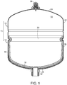
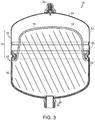
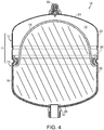
- FIGS. 1-4 an exemplary pre-pressurized expansion tank 10 is shown. It is noted that the general features of the expansion tank 10 can be in accordance with known expansion tanks, and the exemplary expansion tank 10 shown in the figures is one example thereof. The features of the expansion tank 10 depicted in the figures are similar to those shown in US Patent No. 5,386,925, issued February 7, 1995 , and entitled Expansion Tank and US Patent No. 7,032,628, issued April 25, 2006 , and entitled Mobile Prepressurized Diaphragm Type Fluid Storage Tank, both of which are incorporated herein by reference.
- the tank 10 has a housing 11, formed by an upper housing 12 and a lower housing 13, that defines an internal cavity 14.
- a deformable diaphragm 16 and a liner 18 are positioned within the cavity 14 and are removably attached to the lower housing 13, for example, by a retaining ring 20 or the like.
- An indicator 30 is positioned at a top portion of the upper housing 12 as is described in more detail below.
- the upper housing 12 has a generally cylindrical side wall 22 and an end wall 24.
- the upper housing 12 can be of any size depending on the desired total volume of tank 10 and can be of the same general design as the lower housing 13.
- a conventional valve 50 such as a "Schrader” valve or the like, is preferably provided in the end wall 24 of the upper housing 12 to allow the addition or removal of air (gas) to/from cavity 14 for pressurizing the tank 10.
- the lower housing 13 also has a generally cylindrical side wall 26 and an end wall 28.
- the lower housing 13 can also be of any size depending on the desired total volume of tank 10.
- a fitting 32 is provided in end wall 28 of lower housing 13 to allow water to flow into and out of the tank 10.
- the sidewall 26 can have a concave groove 34 formed around its circumference, which can mate with grooves formed in the diaphragm 16, liner 18 and retaining ring 20, as described below.
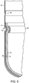
- the sidewall 26 can further have an inset portion 36 (as best shown in Fig. 5 ) formed at an end of the sidewall 26, which creates an overlap joint with the sidewall 22 of the upper housing 12 when the tank 10 is assembled. Once assembled, the upper housing 12 can be welded or otherwise secured to the lower housing 13.
- the upper and lower housings 12, 13 and retaining ring 20 can be made of any suitable material capable of withstanding the pressure desired and compatible with the fluids to be stored and dispensed.
- High strength structural steel is one conventional material that has been used for making the upper and lower housings 12, 13 and retaining ring 20 and allows the upper and lower housings 12, 13 to be joined together by a welding process.
- a mechanical joint also can be used to join upper and lower housings 12, 13 which can be formed of any materials, as long as it provides a structural hermetic seal.
- the retaining ring 20 is arcuate with a concave outer portion and a convex inner portion, which corresponds to and mates with the groove 34 in the sidewall 26, the groove 17 in the diaphragm 16, and the groove 19 in the liner 18, as described in more detail below, to anchor the diaphragm 16 and liner 18 in place and provide a water and gas tight seal.
- the diaphragm 16 is flexible and is preferably made of an elastomer, such as butyl rubber, and is disposed inside of the lower housing 13. As shown in Fig. 5 , the diaphragm 16 has an inwardly protruding groove 17 adjacent its end and is situated so that its end is adjacent the end of liner 18. As such, the groove 17 corresponds to and mates with the groove 34 of the lower housing 13 and the retaining ring 20 to mechanically lock or secure the diaphragm 16 to the lower housing 13. According to various embodiments, the diaphragm 16 is preferably molded to conform to the inner shape of lower housing 13. Thus, the diaphragm 16 is compressed between retaining ring 20 and sidewall 26 of lower housing 13, forming a hermetic seal against air and the fluid.
- an elastomer such as butyl rubber
- the liner 18 is preferably made of a liquid-impervious material, such as polypropylene, and is disposed to cover the inner surface of the lower housing 13. As shown, the liner 18 is positioned between the lower housing 13 and diaphragm 16.
- the liner 18 also preferably has an inwardly protruding groove 19 adjacent its end and is situated so that its end is adjacent the end of the diaphragm 16.
- the groove 19 corresponds to and mates with the groove 34 of the lower housing 13 and retaining ring 20 to mechanically lock or secure liner 18 to the lower housing 13.
- the liner 18 is compressed between retaining ring 20 and sidewall 26 of the lower housing 13, forming a hermetic seal against air and the fluid.
- the portion of the cavity 14 disposed between the liner 18 and diaphragm 16 forms a water receiving portion of cavity 14.
- the water is, thus, contained between liner 18 and diaphragm 16 so that the entire inner surface of upper and lower housings 12, 13 is shielded from the water.
- corrosion of the tank 10 can be prevented.
- the liner 18 also has an aperture that aligns with fitting 32 and provides a liquid tight seal with fitting 32 to prevent water in the tank 10 from flowing between the liner 18 and fitting 32.
- an indicator 30 is provided in the end wall 24 of the upper housing 12 of the tank 10.
- the indicator 30 is in communication with the contents of the cavity 14, particularly the contents of the cavity 14 positioned above the diaphragm 16.
- the indicator 30 is in communication with the pressurized gas portion, which is between the upper end wall 24 and the diaphragm 16.
- the indicator 30 is in communication with the valve 50 so as to allow the contents of the tank to come into contact with the indicator 30 via the valve 50.
- the indicator 30 may be configured to cover or enclose a portion of the valve 50 on the exterior surface of the tank 10.
- the indicator encloses the valve 50 on the exterior surface of the tank 10 such that actuation of the valve 50 to expels the contents (pressurized gas) of the tank 10 positioned above the diaphragm 16 results in the pressurized gas entering the indicator 30 and being contained therein.
- the indicator 30 is installed in connection with the tank 10, preferably in connection with the valve 50, in such a way that an air-tight seal is formed between the indicator 30 and the tank 10.
- the indicator 30 may include one or more seals to ensure an air-tight seal between the indicator 30 and the tank 10 such that contents of the tank will not leak out through the indicator 30 over time.
- the indicator 30 can be configured so as to display a particular color when the amount of moisture in the pressurized gas side of the tank 10 is within acceptable limits, and to display a different color when the amount of moisture is above acceptable limits.
- the indicator 30 can display a color that will stand out from the other nearby components of the tank 10 (e.g., red, orange or the like) when the amount of moisture in the pressurized gas side of the tank 10 is above acceptable limits.
- the indicator 30 will display a different color when the amount of moisture in the pressurized gas side of the tank 10 is within acceptable limits.
- the different color may, for example, be any color similar to nearby components of the tank 10 so as to blend in (e.g., black, grey, silver, white, etc.).
- the indicator 30 provides a user with a simple visual mechanism by which it can be determined whether or not there are operational problems in the tank 10. Such a simple visual mechanism can alert a user to early problems present in the tank 10 that can potentially be addressed by routine maintenance, thereby potentially avoiding further failure of the tank 10 that may result is system performance reduction or subsequent system component failures. Further the visual mechanism can alert a user to tank failure, thereby allowing a user to replace a failed tank in a more timely manner.
- the indicator 30 can be of any configuration that will cover or encase the portion of the tank 10 (e.g. valve 50 on the exterior of the tank 10) and that will allow the contents of the tank expelled from the valve 50 to enter the indicator 30 and be contained therein.
- the indicator 30 can have an overall dome-like shape (such as that shown in Figs. 6A-B ), box-like shape, cylindrical shape, cone-like shape, etc.
- the indicator 30 includes an upper cap 40, side walls 46 extending from the cap 40 and engaging the outer surface of the tank 10, and a cap insert 42 at least partially disposed within the cap 40.
- the cap 40 can have a generally domed rounded structure as shown in the figures, or it can be of any other configuration that allows it to contain at least a portion of the cap insert 42 therein.
- the indicator 30 is fabricated of a transparent material through which a user can view the contents of the indicator 30.
- the indicator 30 is fabricated of a transparent material in at least a portion that allows a user to clearly view the cap insert 42.
- the entire cap 40 can be made transparent, as shown in Fig. 6B so as to allow easy and unobstructed viewing of the cap insert 42 therethrough.
- the remainder of the indicator 30, such as the side walls 46 can be fabricated of a non-transparent material, or can be fabricated of a transparent material, if desired.
- At least a portion of the cap insert 42 is fabricated so as to display a second color when it is exposed to predetermined levels of moisture or to display water if a water volume is present, and to display a first color when it is under normal operating conditions.
- an "acceptable" level of moisture is the level below that which is detectable by the cap insert 42 in order to trigger the cap insert 42 to change color.
- the cap insert 42 can be fabricated so as to display a first color when it is exposed to no moisture or less than detectable levels of moisture, and to display a second color when it is exposed to any level of moisture greater than about zero (e.g., detectable levels of moisture).
- a user can simply view the cap insert 42 through the cap 40 to determine the color of the cap insert 42 and, as a result, be alerted as to the functioning of the tank 10.
- the cap 40 is fabricated of material that optically magnifies the contents of the cap 40 viewed therethrough. As such, one can more easily view the cap insert 42 and see the color so as to determine whether the tank 10 is "good” or "faulty".
- the cap insert 42 has an upper portion 44, which can be dome-like in shape as shown in Fig. 6B , that projects into the cap 40 portion of the insert 30.
- the upper portion 44 is configured and disposed within the cap 40 so as to be clearly visible through the cap 40.
- the cap insert 42 (e.g. the upper portion 44 which is visible through the cap 40) is formed to have a first color which is the color that indicates that the tank is functioning properly.
- a first color of the cap insert 42 is preferably one which is in contrast with the color of deposited rust, which is typically a red-orange-brown- color.
- the cap insert 42 is a light color such as a bright white color, which provides a sharp contrast with deposited rust.
- the bright white or other color of the cap insert 42 can be provided by any conventional method.
- the material forming the cap insert 42 (or a portion of the cap insert 42, such as the upper portion 44, visible through the cap 40) can itself be one which is the desired first color.
- the cap insert 42 or portion thereof can be molded or otherwise formed from a white or other colored plastic material into the desired shape.
- the cap insert 42 can be formed of any material of any color and can be subsequently colored as desired.
- At least a portion of the indicator 30 which is in communication with the cap insert 42 is formed of a material that will corrode and rust when exposed to moisture.
- the tank 10 including the pressurized gas side, of a material that is resistant to corrosion.
- the tank 10 is tested so as to allow pressurized gas from the pressurized gas side of the tank to enter to indicator 30. If moisture is present in the pressurized gas, it will corrode and rust the portion of the indicator 30. This corrosion and rust present in the internal environment of the indicator 30 will quickly deposit rust residue onto the surface of the cap insert 42.
- a further embodiment is that water droplets or a water volume will accumulate in between the cap insert 42 and the cap 40 where it will be visible in the upper portion 44.
- At least a portion of the cap insert 42 visible through the cap 40 is coated with a hydrochromic ink.
- Hydrochromic inks are well known and will not be described in great detail herein. Rather, such known hydrochromic inks can suitably be used.
- the hydrochromic ink can display a first color when it is in normal operating condition, and can display a second color when it is in contact with a predetermined amount of moisture or greater (e.g. a detectable level of moisture, such as greater than trace levels of moisture or greater than zero moisture).
- a predetermined amount of moisture or greater e.g. a detectable level of moisture, such as greater than trace levels of moisture or greater than zero moisture.
- the upper portion 44 or other desired portion of the cap insert 42
- Any contact of the hydrochromic ink coated portion with the predetermined amount of moisture or greater will result in the ink displaying the second color, indicating problems with the tank.
- the second color is preferably any color that will stand out to a user, for example, red, orange, etc.
- the second color can be any color different than the first color (e.g. white, silver, grey etc.).
- the hydrochromic ink can display the first color when it is in contact with less than the predetermined amount of moisture, and can become transparent when it comes into contact with the predetermined amount of moisture or greater.
- the upper portion 44 (or other desired portion of the cap insert 42) can be coated with the second color that alerts a user when there is a problem with the tank (e.g. excessive moisture/any amount of moisture).
- the second color can then be coated with the hydrochromic ink. Any contact of the hydrochromic ink coated portion with the predetermined amount of moisture or greater will result in the ink becoming transparent to thereby reveal the second color.
- the upper portion 44 of the cap insert 42 is provided with a white band (or any other color different than the second color) of hydrochromic ink radially around the cap insert 42.
- the white band remains white (or the other color different than the second color) then the tank is considered to be "good” (i.e., no moisture/acceptable levels of moisture present in the pressurized gas side of the tank 10). If water leaks into the pressurized gas side of the tank 10, the water will make its way into the cap 40 of the indicator 30 through the valve 50 together with the pressurized gas (or other means through which pressurized gas exits the tank 10).
- the pressurized gas containing the water enters into the cap 40 and comes into contact with the hydrochromic ink on the cap insert 42.
- the water will turn the hydrochromic ink invisible, revealing the second color (e.g. red) underneath (or will change the color of the hydrochromic ink to the second color).
- the change in color e.g., from white to red
- the cap insert 42 is colored a second color and is then coated with a hydrochromic ink of a first color that (1) becomes transparent to reveal the second color beneath it when contacted with the predetermined amount of moisture or greater, and returns back to the first color once the moisture has dried out, or (2) changes to the second color when contacted with the predetermined amount of moisture or greater, and returns back to the first color once the moisture has dried out.
- the indicator 30 is reusable and, thus, does not need to be replaced once it has come into contact with moisture and has changed color.
- the indicator 30 can be designed to have two plastic molded gaskets, which act as a primary seal 47 and a secondary seal 48.
- the various parts of the indicator 30 can be formed through any method, such as molding and the like.
- the cap 40 is molded to form a transparent material and the cap insert 42 is molded in a natural or white color and is thereafter colored with the second color and the first color.
- the various components can be assembled and attached using sonic welding or similar methods that will ensure a good hermetic seal is made.
- the primary seal 47 may be disposed at an upper location of the indicator 30 between the cap insert 42 and the valve 50 so as to form a seal between the end of the valve 50 and the upper portion 44 of the indicator 30.
- the secondary seal 48 can be disposed at a bottom part of the indicator 30 between the valve 50 and the top surface of the tank 10 to provide a seal therebetween that will prevent passage of gas and liquids between indicator 30 and the exterior of the indicator 30.
- valve 50 is actuated to allow pressurized gas inside the tank 10 to enter the indicator 30, particularly to enter the cap 40 and come into contact with the cap insert 42. If the pressurized gas within an acceptable level then the cap insert 42 remains unchanged in color. On the other hand, if moisture is present in the pressurized gas above an acceptable level, then the cap insert 42 changes color.
- the cap insert 42 or portion thereof is a first color and at least a portion of the pressurized gas side of the tank 10 is fabricated of a material that corrodes and rusts when contacted with moisture.
- the cap insert 42 or portion thereof is a second color and at least a portion of the indicator 30 which is in communication with the cap insert 42 is formed of a material that will corrode and rust when exposed to moisture.
- the material forming the pressurized gas side of the tank 10 or the cap insert 42 will corrode and rust when exposed to the pressurized gas containing the moisture.
- This corrosion and rust present in the internal environment will quickly deposit rust residue onto the surface of the cap insert 42.
- This deposited rust changes the color of the cap insert 42, thus indicating that there is an excessive amount of moisture in the pressurized gas side of the tank 10. If the moisture in the pressurized gas is within an acceptable level, then the corrosion and rusting does not occur and the color does not change from the first color, indicating that the amount of moisture in the pressurized gas side of the tank 10 is acceptable.
- the cap insert 42 is colored a second color (e.g. red) and is then colored a first color using a hydrochromic ink. If moisture is present in the pressurized gas above an acceptable level, then the hydrochromic ink becomes transparent and the cap insert 42 changes color to the second color to indicate that there is an excessive amount of moisture in the pressurized gas side of the tank 10. If the moisture in the pressurized gas is within an acceptable level, then the hydrochromic ink does not change, and the cap insert 42 displays the first color to indicate that the amount of moisture in the pressurized gas side of the tank 10 is acceptable.
- a second color e.g. red
- the present design helps a homeowner and/or plumber to visually inspect the tank 10 on a more regular basis without having to remove the tank 10 from the system. As such, the plumber or homeowner can be more pro-active with maintaining the equipment being used.
- the present indicator 30 can also beneficially adapt easily to any existing tank having a common valve, e.g. a Schrader style air valve, which is present on all expansion tanks. As such, the indicator 30 can be simply attached to the tank 10 about the valve 50 without requiring any modification to the tank 10 design itself.
- the indicator may be adapted with the appropriate electronics/software to forward an alert to an email address, cellular phone, or smart phone to alert the user if moisture has been detected.
Landscapes
- Engineering & Computer Science (AREA)
- General Engineering & Computer Science (AREA)
- Mechanical Engineering (AREA)
- Physics & Mathematics (AREA)
- Chemical & Material Sciences (AREA)
- Fluid Mechanics (AREA)
- Combustion & Propulsion (AREA)
- Thermal Sciences (AREA)
- General Physics & Mathematics (AREA)
- Analytical Chemistry (AREA)
- Filling Or Discharging Of Gas Storage Vessels (AREA)
- Pipeline Systems (AREA)
- Steam Or Hot-Water Central Heating Systems (AREA)
- Details Of Rigid Or Semi-Rigid Containers (AREA)
Claims (12)
- Réservoir d'expansion à membrane (10), comprenant :un boîtier (11) comprenant une paroi d'extrémité supérieure (24), une paroi latérale (22, 26) et une paroi d'extrémité inférieure (28), la paroi d'extrémité supérieure, la paroi latérale et la paroi d'extrémité inférieure définissant une cavité (14) ;une membrane souple (16) positionnée dans la cavité et reliée à la paroi latérale, la membrane séparant la cavité en une partie supérieure et une partie inférieure, où la partie supérieure de la cavité est scellée de manière à contenir un gaz sous pression et la partie inférieure est scellée de manière à contenir un fluide sous pression ;un indicateur (30) disposé sur la paroi d'extrémité supérieure du boîtier, l'indicateur étant en communication avec le gaz sous pression dans la partie supérieure de la cavité, l'indicateur comprenant un insert (42) qui affiche une première couleur dans des conditions de fonctionnement normales et qui affiche une deuxième couleur lorsqu'il est en contact avec un gaz sous pression contenant un niveau d'humidité supérieur ou égal à un niveau prédéterminé,le réservoir d'expansion à membrane étant caractérisé en ce queau moins une partie de l'insert est colorée de la première couleur, au moins une partie du boîtier formant la partie supérieure de la cavité est formée d'un matériau qui se corrode et rouille lorsqu'il est mis en contact avec le niveau d'humidité supérieur ou égal au niveau prédéterminé, où des résidus de rouille provenant de la partie supérieure de la cavité se déposent sur une surface de l'insert pour afficher ainsi la deuxième couleur, et où la première couleur est une couleur claire.
- Réservoir d'expansion à membrane de la revendication 1, dans lequel l'indicateur comprend en outre un capuchon (40) au niveau d'une partie supérieure, l'insert étant au moins partiellement disposé dans le capuchon et des parois latérales (46) s'étendant vers le bas depuis le capuchon jusqu'à la paroi d'extrémité supérieure du boîtier, où un joint étanche aux gaz et aux fluides est formé entre l'indicateur et la paroi d'extrémité supérieure du boîtier.
- Réservoir d'expansion à membrane de la revendication 2, dans lequel au moins une partie du capuchon est fabriquée en un matériau transparent à travers lequel l'insert est visible.
- Réservoir d'expansion à membrane de la revendication 1, dans lequel au moins une partie du capuchon est fabriquée en un matériau optiquement grossissant, dans lequel l'insert de capuchon peut être visualisé et agrandi à travers celui-ci.
- Réservoir d'expansion à membrane de la revendication 1, dans lequel l'indicateur est disposé de manière à entourer une vanne (50) sur la paroi d'extrémité supérieure du boîtier, la vanne étant en communication avec le gaz sous pression dans la partie supérieure de la cavité.
- Réservoir d'expansion à membrane de la revendication 1, dans lequel le niveau d'humidité prédéterminé est une quantité infime d'humidité.
- Réservoir d'expansion à membrane de la revendication 1, dans lequel le niveau d'humidité prédéterminé est d'environ zéro.
- Réservoir d'expansion à membrane (10), comprenant :un boîtier (11) comprenant une paroi d'extrémité supérieure (24), une paroi latérale (22, 26) et une paroi d'extrémité inférieure (28), la paroi d'extrémité supérieure, la paroi latérale et la paroi d'extrémité inférieure définissant une cavité (14) ;une membrane souple (16) positionnée dans la cavité et reliée à la paroi latérale, la membrane séparant la cavité en une partie supérieure et une partie inférieure, où la partie supérieure de la cavité est scellée de manière à contenir un gaz sous pression et la partie inférieure est scellée de manière à contenir un fluide sous pression ;un indicateur (30) disposé sur la paroi d'extrémité supérieure du boîtier, l'indicateur étant en communication avec le gaz sous pression dans la partie supérieure de la cavité, l'indicateur comprenant un insert (42) qui affiche une première couleur dans des conditions de fonctionnement normales et qui affiche une deuxième couleur lorsqu'il est en contact avec un gaz sous pression contenant un niveau d'humidité supérieur ou égal à un niveau prédéterminé,le réservoir d'expansion à membrane étant caractérisé en ce queau moins une partie de l'insert est colorée de la première couleur, au moins une partie de l'indicateur est formée d'un matériau qui se corrode et rouille lorsqu'il est mis en contact avec le niveau d'humidité supérieur ou égal au niveau prédéterminé, où des résidus de rouille provenant de l'indicateur se déposent sur une surface de l'insert pour afficher ainsi la deuxième couleur, et où la première couleur est une couleur claire.
- Procédé pour déterminer si un niveau supérieur à un niveau d'humidité acceptable est présent dans un côté gaz sous pression d'un réservoir d'expansion à membrane, comprenant le fait :de fournir un indicateur sur une paroi d'extrémité supérieure du réservoir d'expansion à membrane, l'indicateur étant en communication avec le côté gaz sous pression du réservoir d'expansion à membrane, l'indicateur comprenant un boîtier et un insert disposé dans celui-ci, l'indicateur étant configuré pour afficher une première couleur dans une condition de fonctionnement normale et pour afficher une deuxième couleur lorsqu'il est en contact avec un niveau d'humidité supérieur ou égal à un niveau prédéterminé,dans lequel au moins une partie de l'insert est colorée de la première couleur, au moins une partie du boîtier formant la partie supérieure de la cavité est formée d'un matériau qui se corrode et rouille lorsqu'il est mis en contact avec le niveau d'humidité supérieur ou égal au niveau prédéterminé, où des résidus de rouille provenant de la partie supérieure de la cavité se déposent sur une surface de l'insert pour afficher ainsi la deuxième couleur, et où la première couleur est une couleur claire ;d'expulser le gaz sous pression du côté du gaz sous pression du réservoir d'expansion à membrane dans le boîtier d'indicateur et de permettre au gaz sous pression d'entrer en contact avec l'insert ;de visualiser l'insert pour déterminer si la première couleur ou la deuxième couleur est affichée ; etde déterminer qu'un niveau supérieur au niveau d'humidité acceptable est présent dans le gaz sous pression si la deuxième couleur est affichée, et de déterminer que le niveau d'humidité acceptable est présent dans le gaz sous pression si la première couleur est affichée.
- Procédé de la revendication 9, dans lequel le niveau d'humidité prédéterminé est une quantité infime d'humidité.
- Procédé de la revendication 9, dans lequel le niveau d'humidité prédéterminé est d'environ zéro.
- Procédé pour déterminer si un niveau supérieur à un niveau d'humidité acceptable est présent dans un côté gaz sous pression d'un réservoir d'expansion à membrane, comprenant le fait :de fournir un indicateur sur une paroi d'extrémité supérieure du réservoir d'expansion à membrane, l'indicateur étant en communication avec le côté gaz sous pression du réservoir d'expansion à membrane, l'indicateur comprenant un boîtier et un insert disposé dans celui-ci, l'indicateur étant configuré pour afficher une première couleur dans une condition de fonctionnement normale et pour afficher une deuxième couleur lorsqu'il est en contact avec un niveau d'humidité supérieur ou égal à un niveau prédéterminé,dans lequel au moins une partie de l'insert est colorée de la première couleur, au moins une partie de l'indicateur est formée d'un matériau qui se corrode et rouille lorsqu'il est mis en contact avec le niveau d'humidité supérieur ou égal au niveau prédéterminé, où des résidus de rouille provenant de l'indicateur se déposent sur une surface de l'insert pour afficher ainsi la deuxième couleur, et où la première couleur est une couleur claire ;d'expulser le gaz sous pression du côté gaz sous pression du réservoir d'expansion à membrane dans le boîtier d'indicateur et de permettre au gaz sous pression d'entrer en contact avec l'insert ;de visualiser l'insert pour déterminer si la première couleur ou la deuxième couleur est affichée ; etde déterminer qu'un niveau supérieur au niveau d'humidité acceptable est présent dans le gaz sous pression si la deuxième couleur est affichée, et de déterminer que le niveau d'humidité acceptable est présent dans le gaz sous pression si la première couleur est affichée.
Applications Claiming Priority (2)
| Application Number | Priority Date | Filing Date | Title |
|---|---|---|---|
| US14/291,894 US9915433B2 (en) | 2014-05-30 | 2014-05-30 | Moisture detecting air cap indicator for expansion tank failure |
| PCT/US2015/032644 WO2015183933A1 (fr) | 2014-05-30 | 2015-05-27 | Indicateur de bouchon à air détectant l'humidité pour défaillance de réservoir d'expansion |
Publications (3)
| Publication Number | Publication Date |
|---|---|
| EP3149385A1 EP3149385A1 (fr) | 2017-04-05 |
| EP3149385A4 EP3149385A4 (fr) | 2018-01-17 |
| EP3149385B1 true EP3149385B1 (fr) | 2020-05-06 |
Family
ID=54699702
Family Applications (1)
| Application Number | Title | Priority Date | Filing Date |
|---|---|---|---|
| EP15800263.4A Active EP3149385B1 (fr) | 2014-05-30 | 2015-05-27 | Indicateur de bouchon à air détectant l'humidité pour défaillance de réservoir d'expansion |
Country Status (8)
| Country | Link |
|---|---|
| US (3) | US9915433B2 (fr) |
| EP (1) | EP3149385B1 (fr) |
| JP (2) | JP2017523352A (fr) |
| CA (2) | CA2949714C (fr) |
| ES (1) | ES2808910T3 (fr) |
| MX (1) | MX395619B (fr) |
| PT (1) | PT3149385T (fr) |
| WO (1) | WO2015183933A1 (fr) |
Cited By (1)
| Publication number | Priority date | Publication date | Assignee | Title |
|---|---|---|---|---|
| RU227260U1 (ru) * | 2024-03-14 | 2024-07-12 | Владимир Викторович Михайлов | Гидроаккумулятор |
Families Citing this family (14)
| Publication number | Priority date | Publication date | Assignee | Title |
|---|---|---|---|---|
| DE102014001283A1 (de) * | 2014-02-01 | 2015-08-06 | Hydac Technology Gmbh | Druckspeicher |
| WO2017023303A1 (fr) | 2015-08-05 | 2017-02-09 | Stren Microlift Technology, Llc | Système de pompage hydraulique à utiliser avec un puits souterrain |
| US10167865B2 (en) | 2015-08-05 | 2019-01-01 | Weatherford Technology Holdings, Llc | Hydraulic pumping system with enhanced piston rod sealing |
| US10519923B2 (en) * | 2015-09-21 | 2019-12-31 | Ut-Battelle, Llc | Near isothermal combined compressed gas/pumped-hydro electricity storage with waste heat recovery capabilities |
| US10724684B2 (en) * | 2016-09-20 | 2020-07-28 | Amtrol Licensing Inc. | Fiberwound tanks |
| US10514129B2 (en) | 2016-12-02 | 2019-12-24 | Amtrol Licensing Inc. | Hybrid tanks |
| KR200483915Y1 (ko) * | 2016-12-28 | 2017-07-11 | 중앙엔지니어링 주식회사 | 팽창탱크용 가변식 공기압 조절 장치 |
| US10988219B1 (en) * | 2017-06-14 | 2021-04-27 | Hadal, Inc. | System and apparatus for integrated pressure compensator |
| DE102018002315A1 (de) * | 2018-03-19 | 2019-09-19 | Hydac Technology Gmbh | Druckspeicher mit einer Überwachungseinrichtung |
| US10809014B1 (en) * | 2018-03-30 | 2020-10-20 | Northrop Grumman Systems Corporation | Thermal storage with bladder tank |
| US12037996B2 (en) | 2020-09-29 | 2024-07-16 | Ut-Battelle, Llc | Fuel driven near isothermal compressor |
| CN113107051A (zh) * | 2021-05-12 | 2021-07-13 | 华能上海燃机发电有限责任公司 | 一种可监测皮囊状态的消防稳压水箱 |
| DE102021003898A1 (de) * | 2021-07-28 | 2023-02-02 | Hydac Technology Gmbh | Druckspeicher |
| GB2619281B (en) * | 2022-05-25 | 2025-01-08 | Cam Lock Ltd | Diaphragm for a fluid storage tank |
Family Cites Families (59)
| Publication number | Priority date | Publication date | Assignee | Title |
|---|---|---|---|---|
| US1579536A (en) * | 1924-08-15 | 1926-04-06 | Hodgson John Lawrence | Flexible diaphragm for use in the measurement of fluid pressure |
| US2716338A (en) * | 1954-04-08 | 1955-08-30 | Welford C Blinn | Button type package humidity indicator |
| US3085424A (en) * | 1959-11-17 | 1963-04-16 | Ansul Chemical Co | Moisture indicator housing |
| US3246758A (en) * | 1963-01-30 | 1966-04-19 | Watsco Inc | Hygrometric indicator for desiccants |
| US3408860A (en) * | 1965-12-03 | 1968-11-05 | Dow Chemical Co | Relative humidity apparatus |
| US3524475A (en) * | 1968-01-10 | 1970-08-18 | American Tube & Controls Inc | Expansion tank |
| US3854885A (en) * | 1970-09-03 | 1974-12-17 | Us Army | Toxic agent leak detector |
| CA983230A (en) | 1972-01-03 | 1976-02-10 | Lawrence Stark | Physiologically compatible plastic contact lenses and a method for their production |
| US3948287A (en) * | 1974-04-12 | 1976-04-06 | Nobuyuki Sugimura | Accumulator |
| US4040790A (en) * | 1976-07-29 | 1977-08-09 | General Electric Company | Moisture and rust detector for hydraulic control systems |
| US4201080A (en) * | 1976-11-24 | 1980-05-06 | Bernard Slepak | Moisture indicator |
| US4181156A (en) * | 1978-12-04 | 1980-01-01 | Greer Hydraulics, Inc. | Pressure accumulator with anti-extrusion gas charging valve assembly |
| US4299254A (en) * | 1980-01-21 | 1981-11-10 | Greer Hydraulics, Incorporated | Pressure accumulator having a long life distensible bladder |
| JPS56146527A (en) * | 1980-04-11 | 1981-11-14 | Shimakura Tekkosho Kk | Pressure water tank |
| EP0063287B1 (fr) * | 1981-04-09 | 1985-06-26 | Wilfried Dreyfuss | Dispositif de protection pour tuyaux |
| JPS60187885U (ja) * | 1984-05-23 | 1985-12-12 | 日本軽金属株式会社 | 冷房装置用受液器 |
| US4595037A (en) * | 1984-12-14 | 1986-06-17 | Essef Industries, Inc. | Split tank closure and diaphragm assembly |
| JPH0210443Y2 (fr) * | 1985-05-14 | 1990-03-15 | ||
| JPH0722000Y2 (ja) * | 1988-12-21 | 1995-05-17 | エスエムシー株式会社 | 管継手 |
| US5062455A (en) * | 1989-08-25 | 1991-11-05 | A. O. Smith Corporation | Pressure vessel with diaphragm compression seal |
| US5253674A (en) * | 1990-04-19 | 1993-10-19 | Long Manufacturing Limited | Coolant corrosiveness indicator |
| CA2146463C (fr) * | 1990-04-19 | 1999-11-02 | Charles S. Argyle | Indicateur de corrosion a fluide de refroidissement |
| US5176178A (en) * | 1991-02-20 | 1993-01-05 | Aos Holding Company | Accumulator with randomly uniplanar bladder collapse |
| JPH0689568A (ja) | 1992-09-09 | 1994-03-29 | Mitsubishi Electric Corp | メモリ素子 |
| US5386925A (en) | 1993-06-21 | 1995-02-07 | Amtrol Inc. | Expansion tank |
| DE9309620U1 (de) | 1993-06-29 | 1993-09-02 | Druck & Temperatur Leitenberger GmbH, 72138 Kirchentellinsfurt | Prüfgerät für ein Druckausgleichsgefäß einer Heizungsanlage |
| US5383338A (en) * | 1993-12-17 | 1995-01-24 | Emerson Electric Co. | In-line sight indicator |
| EP0684429B1 (fr) * | 1994-04-27 | 1998-11-04 | Stücklin & Cie AG | Vase d'expansion pour installations remplies de fluide |
| JP2932150B2 (ja) * | 1994-06-23 | 1999-08-09 | 株式会社戸上電機製作所 | 水浸入を検知できるようにした開閉器 |
| KR960024100A (ko) | 1994-12-27 | 1996-07-20 | 배순훈 | 압력검출수단을 갖는 밀폐식 가스보일러의 팽창탱크 |
| JPH1072093A (ja) * | 1996-05-02 | 1998-03-17 | Sayama Seisakusho:Kk | 圧力タンク |
| JPH10317521A (ja) * | 1997-05-23 | 1998-12-02 | Nitto Denko Corp | 漏水検知シール材 |
| US6576473B1 (en) * | 1999-05-28 | 2003-06-10 | Mainstream Engineering Corporation | Removable test kit and method of use for vapor compression systems |
| US6401966B2 (en) * | 2000-05-23 | 2002-06-11 | Fu Chung Tsai | Plastic pressure vessel structure |
| JP4678991B2 (ja) * | 2001-06-12 | 2011-04-27 | 大阪瓦斯株式会社 | 流量計測装置 |
| US6564742B2 (en) * | 2001-08-03 | 2003-05-20 | Hewlett-Packard Development Company, Llp | Over-temperature warning device |
| US20030056711A1 (en) * | 2001-09-26 | 2003-03-27 | Tranter Brian R. | Pressure indication device |
| DE10233454A1 (de) * | 2002-07-24 | 2004-02-12 | Hydac Technology Gmbh | Hydrospeicher |
| US20040173624A1 (en) * | 2003-03-05 | 2004-09-09 | Polymer & Steel Technologies Holding Company, L.L.C. | Vessel diaphragm and method |
| US7032628B2 (en) | 2003-04-30 | 2006-04-25 | Amtrol, Inc. | Mobile prepressurized diaphragm type fluid storage tank |
| NL1023595C2 (nl) * | 2003-06-04 | 2004-12-07 | Flamco Bv | Expansievat. |
| JP3823321B2 (ja) | 2003-12-25 | 2006-09-20 | 有限会社エスアールジェイ | バルーン制御装置 |
| JP2007537109A (ja) * | 2004-05-12 | 2007-12-20 | アムトロール,インコーポレーテッド | 内部ダイアフラムを有する非金属膨張タンクおよびダイアフラム用締め付け装置 |
| US8633825B2 (en) | 2006-08-08 | 2014-01-21 | Wessels Company | Expansion tank with a predictive sensor |
| US20080035647A1 (en) | 2006-08-08 | 2008-02-14 | James Fuller | Expansion tank with a predictive sensor |
| KR200430638Y1 (ko) | 2006-08-08 | 2006-11-10 | (주)에쎈테크 | 수분지시계 |
| JPWO2008081835A1 (ja) | 2006-12-28 | 2010-04-30 | クオリカプス株式会社 | 水濡れインジケーターおよびタイムインジケーター |
| NZ571375A (en) | 2008-09-18 | 2011-05-27 | Kyle Lloyd Herbert | Building sheet and method for detecting weatherproofness of structures |
| TWI350807B (en) * | 2008-10-07 | 2011-10-21 | Li Ming Wang | Pressure tank having plural access openings |
| US8523001B2 (en) * | 2009-12-07 | 2013-09-03 | Advanced Conservation Technology Distribution, Inc. | Thermal expansion/surge reduction water tank |
| KR200462979Y1 (ko) * | 2010-08-27 | 2012-10-11 | 양재구 | 누수 감지 기능을 구비한 격막식 팽창탱크 |
| CN202266670U (zh) * | 2011-09-01 | 2012-06-06 | 沛毅工业股份有限公司 | 具有快速接头的储水压力桶 |
| KR200460511Y1 (ko) * | 2011-10-17 | 2012-05-25 | 성낙경 | 블래더 감지 기능을 구비한 압력탱크 |
| JP5331189B2 (ja) | 2011-11-21 | 2013-10-30 | 三星ダイヤモンド工業株式会社 | 基板ブレーク装置 |
| US8403170B1 (en) * | 2012-04-20 | 2013-03-26 | Ming-Yu Lai | Pressure vessel |
| KR101428756B1 (ko) | 2012-08-24 | 2014-09-23 | (주)에스엠테크 | 격막의 팽창을 감지하는 밀폐형 팽창탱크 |
| US9146137B2 (en) * | 2012-12-12 | 2015-09-29 | Amtrol Licensing Inc. | Air cell indicator |
| EP2969582B1 (fr) * | 2013-03-15 | 2021-06-02 | Segan Industries, Inc. | Composés pour réduire la couleur de fond dans des compositions de changement de couleur |
| JP6055086B2 (ja) * | 2013-04-03 | 2016-12-27 | 日本ペイント・サーフケミカルズ株式会社 | アルミニウム製熱交換器の表面処理方法 |
-
2014
- 2014-05-30 US US14/291,894 patent/US9915433B2/en active Active
-
2015
- 2015-05-27 JP JP2016567718A patent/JP2017523352A/ja active Pending
- 2015-05-27 CA CA2949714A patent/CA2949714C/fr active Active
- 2015-05-27 PT PT158002634T patent/PT3149385T/pt unknown
- 2015-05-27 WO PCT/US2015/032644 patent/WO2015183933A1/fr not_active Ceased
- 2015-05-27 CA CA3189253A patent/CA3189253A1/fr active Pending
- 2015-05-27 ES ES15800263T patent/ES2808910T3/es active Active
- 2015-05-27 MX MX2016015802A patent/MX395619B/es unknown
- 2015-05-27 EP EP15800263.4A patent/EP3149385B1/fr active Active
-
2018
- 2018-03-05 US US15/911,787 patent/US10323848B2/en active Active
-
2019
- 2019-02-06 US US16/269,064 patent/US11156369B2/en active Active
-
2020
- 2020-11-11 JP JP2020187919A patent/JP7113058B2/ja active Active
Non-Patent Citations (1)
| Title |
|---|
| None * |
Cited By (1)
| Publication number | Priority date | Publication date | Assignee | Title |
|---|---|---|---|---|
| RU227260U1 (ru) * | 2024-03-14 | 2024-07-12 | Владимир Викторович Михайлов | Гидроаккумулятор |
Also Published As
| Publication number | Publication date |
|---|---|
| MX2016015802A (es) | 2017-02-27 |
| US20180195740A1 (en) | 2018-07-12 |
| MX395619B (es) | 2025-03-25 |
| JP2021046942A (ja) | 2021-03-25 |
| ES2808910T3 (es) | 2021-03-02 |
| CA2949714A1 (fr) | 2015-12-03 |
| US20150345802A1 (en) | 2015-12-03 |
| JP2017523352A (ja) | 2017-08-17 |
| EP3149385A4 (fr) | 2018-01-17 |
| JP7113058B2 (ja) | 2022-08-04 |
| CA2949714C (fr) | 2023-04-04 |
| CA3189253A1 (fr) | 2015-12-03 |
| US20190170370A1 (en) | 2019-06-06 |
| US10323848B2 (en) | 2019-06-18 |
| US9915433B2 (en) | 2018-03-13 |
| EP3149385A1 (fr) | 2017-04-05 |
| US11156369B2 (en) | 2021-10-26 |
| WO2015183933A1 (fr) | 2015-12-03 |
| PT3149385T (pt) | 2020-05-29 |
Similar Documents
| Publication | Publication Date | Title |
|---|---|---|
| US11156369B2 (en) | Moisture detecting air cap indicator for expansion tank failure | |
| US9146137B2 (en) | Air cell indicator | |
| US9664206B2 (en) | Pressure accumulator | |
| KR20130015775A (ko) | 배출관 케이스가 결합된 차량용 내압용기 가스누출감지장치 | |
| US6578408B1 (en) | Testing fluid-containing systems | |
| KR102287932B1 (ko) | 가스유출 감지기능을 갖는 씰, 이를 구비한 고압가스용기 및 고압가스용기의 가스유출 모니터링 시스템 | |
| US11326978B2 (en) | Leak indicating clamp | |
| CN214998507U (zh) | 液压蓄能器 | |
| US8800588B2 (en) | Glass bulb thermally-activated pressure relief device, safety inspection method, and equipment | |
| US7216530B2 (en) | Fluid containment element leak detection apparatus and method | |
| US20170082517A1 (en) | Leak detection system | |
| EP0026575A1 (fr) | Dispositif protecteur contre la surpression avec soupape et indicateur de pression | |
| US20250102115A1 (en) | Sight glass indicator for tank failure | |
| CN213576839U (zh) | 一种液体窥视器 | |
| US20250129802A1 (en) | Pressure Accumulator | |
| WO2019234515A1 (fr) | Adaptateur fileté pour le vidage rapide de fûts/boîtes contenant un liquide | |
| IE46051B1 (en) | Improvements in a leak detector valve assembly | |
| JP2002048621A (ja) | 多重ガラス式液面計 | |
| JPH09250942A (ja) | ドラム罐液面指示計 | |
| NO178479B (no) | Kalibreringsblokk |
Legal Events
| Date | Code | Title | Description |
|---|---|---|---|
| STAA | Information on the status of an ep patent application or granted ep patent |
Free format text: STATUS: THE INTERNATIONAL PUBLICATION HAS BEEN MADE |
|
| PUAI | Public reference made under article 153(3) epc to a published international application that has entered the european phase |
Free format text: ORIGINAL CODE: 0009012 |
|
| STAA | Information on the status of an ep patent application or granted ep patent |
Free format text: STATUS: REQUEST FOR EXAMINATION WAS MADE |
|
| 17P | Request for examination filed |
Effective date: 20161130 |
|
| AK | Designated contracting states |
Kind code of ref document: A1 Designated state(s): AL AT BE BG CH CY CZ DE DK EE ES FI FR GB GR HR HU IE IS IT LI LT LU LV MC MK MT NL NO PL PT RO RS SE SI SK SM TR |
|
| AX | Request for extension of the european patent |
Extension state: BA ME |
|
| RIN1 | Information on inventor provided before grant (corrected) |
Inventor name: VAN HAAREN, CHRISTOPHER, A. Inventor name: KAMPF, CHRISTOPHER Inventor name: CERPOVICZ, KENNETH |
|
| DAV | Request for validation of the european patent (deleted) | ||
| DAX | Request for extension of the european patent (deleted) | ||
| A4 | Supplementary search report drawn up and despatched |
Effective date: 20171215 |
|
| RIC1 | Information provided on ipc code assigned before grant |
Ipc: F16L 55/053 20060101ALI20171211BHEP Ipc: F16L 55/04 20060101ALI20171211BHEP Ipc: G01M 3/04 20060101ALI20171211BHEP Ipc: F24D 3/10 20060101AFI20171211BHEP Ipc: G01M 3/00 20060101ALI20171211BHEP |
|
| REG | Reference to a national code |
Ref country code: DE Ref legal event code: R079 Ref document number: 602015052377 Country of ref document: DE Free format text: PREVIOUS MAIN CLASS: F16L0055040000 Ipc: F24D0003100000 |
|
| RIC1 | Information provided on ipc code assigned before grant |
Ipc: F15B 1/14 20060101ALI20191219BHEP Ipc: F15B 20/00 20060101ALI20191219BHEP Ipc: F16L 55/04 20060101ALI20191219BHEP Ipc: G01M 3/00 20060101ALI20191219BHEP Ipc: F16L 55/053 20060101ALI20191219BHEP Ipc: G01M 3/04 20060101ALI20191219BHEP Ipc: F24D 3/10 20060101AFI20191219BHEP |
|
| GRAP | Despatch of communication of intention to grant a patent |
Free format text: ORIGINAL CODE: EPIDOSNIGR1 |
|
| STAA | Information on the status of an ep patent application or granted ep patent |
Free format text: STATUS: GRANT OF PATENT IS INTENDED |
|
| INTG | Intention to grant announced |
Effective date: 20200127 |
|
| GRAS | Grant fee paid |
Free format text: ORIGINAL CODE: EPIDOSNIGR3 |
|
| GRAA | (expected) grant |
Free format text: ORIGINAL CODE: 0009210 |
|
| STAA | Information on the status of an ep patent application or granted ep patent |
Free format text: STATUS: THE PATENT HAS BEEN GRANTED |
|
| AK | Designated contracting states |
Kind code of ref document: B1 Designated state(s): AL AT BE BG CH CY CZ DE DK EE ES FI FR GB GR HR HU IE IS IT LI LT LU LV MC MK MT NL NO PL PT RO RS SE SI SK SM TR |
|
| REG | Reference to a national code |
Ref country code: GB Ref legal event code: FG4D |
|
| REG | Reference to a national code |
Ref country code: CH Ref legal event code: EP Ref country code: AT Ref legal event code: REF Ref document number: 1267385 Country of ref document: AT Kind code of ref document: T Effective date: 20200515 |
|
| REG | Reference to a national code |
Ref country code: IE Ref legal event code: FG4D |
|
| REG | Reference to a national code |
Ref country code: DE Ref legal event code: R096 Ref document number: 602015052377 Country of ref document: DE |
|
| REG | Reference to a national code |
Ref country code: PT Ref legal event code: SC4A Ref document number: 3149385 Country of ref document: PT Date of ref document: 20200529 Kind code of ref document: T Free format text: AVAILABILITY OF NATIONAL TRANSLATION Effective date: 20200521 |
|
| REG | Reference to a national code |
Ref country code: LT Ref legal event code: MG4D |
|
| REG | Reference to a national code |
Ref country code: NL Ref legal event code: MP Effective date: 20200506 |
|
| PG25 | Lapsed in a contracting state [announced via postgrant information from national office to epo] |
Ref country code: LT Free format text: LAPSE BECAUSE OF FAILURE TO SUBMIT A TRANSLATION OF THE DESCRIPTION OR TO PAY THE FEE WITHIN THE PRESCRIBED TIME-LIMIT Effective date: 20200506 Ref country code: FI Free format text: LAPSE BECAUSE OF FAILURE TO SUBMIT A TRANSLATION OF THE DESCRIPTION OR TO PAY THE FEE WITHIN THE PRESCRIBED TIME-LIMIT Effective date: 20200506 Ref country code: IS Free format text: LAPSE BECAUSE OF FAILURE TO SUBMIT A TRANSLATION OF THE DESCRIPTION OR TO PAY THE FEE WITHIN THE PRESCRIBED TIME-LIMIT Effective date: 20200906 Ref country code: SE Free format text: LAPSE BECAUSE OF FAILURE TO SUBMIT A TRANSLATION OF THE DESCRIPTION OR TO PAY THE FEE WITHIN THE PRESCRIBED TIME-LIMIT Effective date: 20200506 Ref country code: GR Free format text: LAPSE BECAUSE OF FAILURE TO SUBMIT A TRANSLATION OF THE DESCRIPTION OR TO PAY THE FEE WITHIN THE PRESCRIBED TIME-LIMIT Effective date: 20200807 Ref country code: NO Free format text: LAPSE BECAUSE OF FAILURE TO SUBMIT A TRANSLATION OF THE DESCRIPTION OR TO PAY THE FEE WITHIN THE PRESCRIBED TIME-LIMIT Effective date: 20200806 |
|
| PG25 | Lapsed in a contracting state [announced via postgrant information from national office to epo] |
Ref country code: BG Free format text: LAPSE BECAUSE OF FAILURE TO SUBMIT A TRANSLATION OF THE DESCRIPTION OR TO PAY THE FEE WITHIN THE PRESCRIBED TIME-LIMIT Effective date: 20200806 Ref country code: HR Free format text: LAPSE BECAUSE OF FAILURE TO SUBMIT A TRANSLATION OF THE DESCRIPTION OR TO PAY THE FEE WITHIN THE PRESCRIBED TIME-LIMIT Effective date: 20200506 Ref country code: RS Free format text: LAPSE BECAUSE OF FAILURE TO SUBMIT A TRANSLATION OF THE DESCRIPTION OR TO PAY THE FEE WITHIN THE PRESCRIBED TIME-LIMIT Effective date: 20200506 Ref country code: LV Free format text: LAPSE BECAUSE OF FAILURE TO SUBMIT A TRANSLATION OF THE DESCRIPTION OR TO PAY THE FEE WITHIN THE PRESCRIBED TIME-LIMIT Effective date: 20200506 |
|
| REG | Reference to a national code |
Ref country code: AT Ref legal event code: MK05 Ref document number: 1267385 Country of ref document: AT Kind code of ref document: T Effective date: 20200506 |
|
| PG25 | Lapsed in a contracting state [announced via postgrant information from national office to epo] |
Ref country code: AL Free format text: LAPSE BECAUSE OF FAILURE TO SUBMIT A TRANSLATION OF THE DESCRIPTION OR TO PAY THE FEE WITHIN THE PRESCRIBED TIME-LIMIT Effective date: 20200506 Ref country code: NL Free format text: LAPSE BECAUSE OF FAILURE TO SUBMIT A TRANSLATION OF THE DESCRIPTION OR TO PAY THE FEE WITHIN THE PRESCRIBED TIME-LIMIT Effective date: 20200506 |
|
| PG25 | Lapsed in a contracting state [announced via postgrant information from national office to epo] |
Ref country code: SM Free format text: LAPSE BECAUSE OF FAILURE TO SUBMIT A TRANSLATION OF THE DESCRIPTION OR TO PAY THE FEE WITHIN THE PRESCRIBED TIME-LIMIT Effective date: 20200506 Ref country code: EE Free format text: LAPSE BECAUSE OF FAILURE TO SUBMIT A TRANSLATION OF THE DESCRIPTION OR TO PAY THE FEE WITHIN THE PRESCRIBED TIME-LIMIT Effective date: 20200506 Ref country code: DK Free format text: LAPSE BECAUSE OF FAILURE TO SUBMIT A TRANSLATION OF THE DESCRIPTION OR TO PAY THE FEE WITHIN THE PRESCRIBED TIME-LIMIT Effective date: 20200506 Ref country code: RO Free format text: LAPSE BECAUSE OF FAILURE TO SUBMIT A TRANSLATION OF THE DESCRIPTION OR TO PAY THE FEE WITHIN THE PRESCRIBED TIME-LIMIT Effective date: 20200506 Ref country code: AT Free format text: LAPSE BECAUSE OF FAILURE TO SUBMIT A TRANSLATION OF THE DESCRIPTION OR TO PAY THE FEE WITHIN THE PRESCRIBED TIME-LIMIT Effective date: 20200506 Ref country code: CH Free format text: LAPSE BECAUSE OF NON-PAYMENT OF DUE FEES Effective date: 20200531 Ref country code: CZ Free format text: LAPSE BECAUSE OF FAILURE TO SUBMIT A TRANSLATION OF THE DESCRIPTION OR TO PAY THE FEE WITHIN THE PRESCRIBED TIME-LIMIT Effective date: 20200506 Ref country code: LI Free format text: LAPSE BECAUSE OF NON-PAYMENT OF DUE FEES Effective date: 20200531 |
|
| REG | Reference to a national code |
Ref country code: DE Ref legal event code: R097 Ref document number: 602015052377 Country of ref document: DE |
|
| PG25 | Lapsed in a contracting state [announced via postgrant information from national office to epo] |
Ref country code: PL Free format text: LAPSE BECAUSE OF FAILURE TO SUBMIT A TRANSLATION OF THE DESCRIPTION OR TO PAY THE FEE WITHIN THE PRESCRIBED TIME-LIMIT Effective date: 20200506 Ref country code: SK Free format text: LAPSE BECAUSE OF FAILURE TO SUBMIT A TRANSLATION OF THE DESCRIPTION OR TO PAY THE FEE WITHIN THE PRESCRIBED TIME-LIMIT Effective date: 20200506 Ref country code: MC Free format text: LAPSE BECAUSE OF FAILURE TO SUBMIT A TRANSLATION OF THE DESCRIPTION OR TO PAY THE FEE WITHIN THE PRESCRIBED TIME-LIMIT Effective date: 20200506 |
|
| REG | Reference to a national code |
Ref country code: ES Ref legal event code: FG2A Ref document number: 2808910 Country of ref document: ES Kind code of ref document: T3 Effective date: 20210302 |
|
| PLBE | No opposition filed within time limit |
Free format text: ORIGINAL CODE: 0009261 |
|
| STAA | Information on the status of an ep patent application or granted ep patent |
Free format text: STATUS: NO OPPOSITION FILED WITHIN TIME LIMIT |
|
| REG | Reference to a national code |
Ref country code: BE Ref legal event code: MM Effective date: 20200531 |
|
| PG25 | Lapsed in a contracting state [announced via postgrant information from national office to epo] |
Ref country code: LU Free format text: LAPSE BECAUSE OF NON-PAYMENT OF DUE FEES Effective date: 20200527 |
|
| 26N | No opposition filed |
Effective date: 20210209 |
|
| PG25 | Lapsed in a contracting state [announced via postgrant information from national office to epo] |
Ref country code: BE Free format text: LAPSE BECAUSE OF NON-PAYMENT OF DUE FEES Effective date: 20200531 Ref country code: SI Free format text: LAPSE BECAUSE OF FAILURE TO SUBMIT A TRANSLATION OF THE DESCRIPTION OR TO PAY THE FEE WITHIN THE PRESCRIBED TIME-LIMIT Effective date: 20200506 |
|
| REG | Reference to a national code |
Ref country code: FR Ref legal event code: PLFP Year of fee payment: 8 |
|
| PG25 | Lapsed in a contracting state [announced via postgrant information from national office to epo] |
Ref country code: TR Free format text: LAPSE BECAUSE OF FAILURE TO SUBMIT A TRANSLATION OF THE DESCRIPTION OR TO PAY THE FEE WITHIN THE PRESCRIBED TIME-LIMIT Effective date: 20200506 Ref country code: MT Free format text: LAPSE BECAUSE OF FAILURE TO SUBMIT A TRANSLATION OF THE DESCRIPTION OR TO PAY THE FEE WITHIN THE PRESCRIBED TIME-LIMIT Effective date: 20200506 Ref country code: CY Free format text: LAPSE BECAUSE OF FAILURE TO SUBMIT A TRANSLATION OF THE DESCRIPTION OR TO PAY THE FEE WITHIN THE PRESCRIBED TIME-LIMIT Effective date: 20200506 |
|
| PG25 | Lapsed in a contracting state [announced via postgrant information from national office to epo] |
Ref country code: MK Free format text: LAPSE BECAUSE OF FAILURE TO SUBMIT A TRANSLATION OF THE DESCRIPTION OR TO PAY THE FEE WITHIN THE PRESCRIBED TIME-LIMIT Effective date: 20200506 |
|
| PGFP | Annual fee paid to national office [announced via postgrant information from national office to epo] |
Ref country code: DE Payment date: 20230526 Year of fee payment: 9 |
|
| PGFP | Annual fee paid to national office [announced via postgrant information from national office to epo] |
Ref country code: IE Payment date: 20240517 Year of fee payment: 10 |
|
| PGFP | Annual fee paid to national office [announced via postgrant information from national office to epo] |
Ref country code: GB Payment date: 20240522 Year of fee payment: 10 |
|
| PGFP | Annual fee paid to national office [announced via postgrant information from national office to epo] |
Ref country code: ES Payment date: 20240614 Year of fee payment: 10 |
|
| PGFP | Annual fee paid to national office [announced via postgrant information from national office to epo] |
Ref country code: FR Payment date: 20240523 Year of fee payment: 10 |
|
| PGFP | Annual fee paid to national office [announced via postgrant information from national office to epo] |
Ref country code: PT Payment date: 20240522 Year of fee payment: 10 |
|
| PGFP | Annual fee paid to national office [announced via postgrant information from national office to epo] |
Ref country code: IT Payment date: 20240531 Year of fee payment: 10 |
|
| REG | Reference to a national code |
Ref country code: DE Ref legal event code: R119 Ref document number: 602015052377 Country of ref document: DE |
|
| PG25 | Lapsed in a contracting state [announced via postgrant information from national office to epo] |
Ref country code: PT Free format text: LAPSE BECAUSE OF NON-PAYMENT OF DUE FEES Effective date: 20251127 |
|
| GBPC | Gb: european patent ceased through non-payment of renewal fee |
Effective date: 20250527 |
|
| PG25 | Lapsed in a contracting state [announced via postgrant information from national office to epo] |
Ref country code: GB Free format text: LAPSE BECAUSE OF NON-PAYMENT OF DUE FEES Effective date: 20250527 |
|
| PG25 | Lapsed in a contracting state [announced via postgrant information from national office to epo] |
Ref country code: DE Free format text: LAPSE BECAUSE OF NON-PAYMENT OF DUE FEES Effective date: 20251202 Ref country code: IE Free format text: LAPSE BECAUSE OF NON-PAYMENT OF DUE FEES Effective date: 20250527 |
|
| PG25 | Lapsed in a contracting state [announced via postgrant information from national office to epo] |
Ref country code: IT Free format text: LAPSE BECAUSE OF NON-PAYMENT OF DUE FEES Effective date: 20250527 |
|
| PG25 | Lapsed in a contracting state [announced via postgrant information from national office to epo] |
Ref country code: FR Free format text: LAPSE BECAUSE OF NON-PAYMENT OF DUE FEES Effective date: 20250531 |