EP3150265A1 - Öltank einer turbomaschine mit entlüfter - Google Patents
Öltank einer turbomaschine mit entlüfter Download PDFInfo
- Publication number
- EP3150265A1 EP3150265A1 EP16190529.4A EP16190529A EP3150265A1 EP 3150265 A1 EP3150265 A1 EP 3150265A1 EP 16190529 A EP16190529 A EP 16190529A EP 3150265 A1 EP3150265 A1 EP 3150265A1
- Authority
- EP
- European Patent Office
- Prior art keywords
- oil
- air
- rotor
- tank
- vent
- Prior art date
- Legal status (The legal status is an assumption and is not a legal conclusion. Google has not performed a legal analysis and makes no representation as to the accuracy of the status listed.)
- Granted
Links
Images
Classifications
-
- F—MECHANICAL ENGINEERING; LIGHTING; HEATING; WEAPONS; BLASTING
- F01—MACHINES OR ENGINES IN GENERAL; ENGINE PLANTS IN GENERAL; STEAM ENGINES
- F01D—NON-POSITIVE DISPLACEMENT MACHINES OR ENGINES, e.g. STEAM TURBINES
- F01D25/00—Component parts, details, or accessories, not provided for in, or of interest apart from, other groups
- F01D25/18—Lubricating arrangements
- F01D25/20—Lubricating arrangements using lubrication pumps
-
- B—PERFORMING OPERATIONS; TRANSPORTING
- B01—PHYSICAL OR CHEMICAL PROCESSES OR APPARATUS IN GENERAL
- B01D—SEPARATION
- B01D19/00—Degasification of liquids
- B01D19/0042—Degasification of liquids modifying the liquid flow
- B01D19/0052—Degasification of liquids modifying the liquid flow in rotating vessels, vessels containing movable parts or in which centrifugal movement is caused
-
- B—PERFORMING OPERATIONS; TRANSPORTING
- B01—PHYSICAL OR CHEMICAL PROCESSES OR APPARATUS IN GENERAL
- B01D—SEPARATION
- B01D19/00—Degasification of liquids
- B01D19/0042—Degasification of liquids modifying the liquid flow
- B01D19/0052—Degasification of liquids modifying the liquid flow in rotating vessels, vessels containing movable parts or in which centrifugal movement is caused
- B01D19/0057—Degasification of liquids modifying the liquid flow in rotating vessels, vessels containing movable parts or in which centrifugal movement is caused the centrifugal movement being caused by a vortex, e.g. using a cyclone, or by a tangential inlet
-
- B—PERFORMING OPERATIONS; TRANSPORTING
- B01—PHYSICAL OR CHEMICAL PROCESSES OR APPARATUS IN GENERAL
- B01D—SEPARATION
- B01D19/00—Degasification of liquids
- B01D19/02—Foam dispersion or prevention
-
- B—PERFORMING OPERATIONS; TRANSPORTING
- B01—PHYSICAL OR CHEMICAL PROCESSES OR APPARATUS IN GENERAL
- B01D—SEPARATION
- B01D45/00—Separating dispersed particles from gases or vapours by gravity, inertia, or centrifugal forces
- B01D45/12—Separating dispersed particles from gases or vapours by gravity, inertia, or centrifugal forces by centrifugal forces
- B01D45/16—Separating dispersed particles from gases or vapours by gravity, inertia, or centrifugal forces by centrifugal forces generated by the winding course of the gas stream, the centrifugal forces being generated solely or partly by mechanical means, e.g. fixed swirl vanes
-
- B—PERFORMING OPERATIONS; TRANSPORTING
- B01—PHYSICAL OR CHEMICAL PROCESSES OR APPARATUS IN GENERAL
- B01D—SEPARATION
- B01D46/00—Filters or filtering processes specially modified for separating dispersed particles from gases or vapours
- B01D46/0052—Filters or filtering processes specially modified for separating dispersed particles from gases or vapours with filtering elements moving during filtering operation
- B01D46/0056—Filters or filtering processes specially modified for separating dispersed particles from gases or vapours with filtering elements moving during filtering operation with rotational movement
-
- B—PERFORMING OPERATIONS; TRANSPORTING
- B04—CENTRIFUGAL APPARATUS OR MACHINES FOR CARRYING-OUT PHYSICAL OR CHEMICAL PROCESSES
- B04C—APPARATUS USING FREE VORTEX FLOW, e.g. CYCLONES
- B04C5/00—Apparatus in which the axial direction of the vortex is reversed
- B04C5/02—Construction of inlets by which the vortex flow is generated, e.g. tangential admission, the fluid flow being forced to follow a downward path by spirally wound bulkheads, or with slightly downwardly-directed tangential admission
- B04C5/04—Tangential inlets
-
- B—PERFORMING OPERATIONS; TRANSPORTING
- B04—CENTRIFUGAL APPARATUS OR MACHINES FOR CARRYING-OUT PHYSICAL OR CHEMICAL PROCESSES
- B04C—APPARATUS USING FREE VORTEX FLOW, e.g. CYCLONES
- B04C9/00—Combinations with other devices, e.g. fans, expansion chambers, diffusors, water locks
-
- F—MECHANICAL ENGINEERING; LIGHTING; HEATING; WEAPONS; BLASTING
- F01—MACHINES OR ENGINES IN GENERAL; ENGINE PLANTS IN GENERAL; STEAM ENGINES
- F01D—NON-POSITIVE DISPLACEMENT MACHINES OR ENGINES, e.g. STEAM TURBINES
- F01D25/00—Component parts, details, or accessories, not provided for in, or of interest apart from, other groups
- F01D25/18—Lubricating arrangements
-
- F—MECHANICAL ENGINEERING; LIGHTING; HEATING; WEAPONS; BLASTING
- F01—MACHINES OR ENGINES IN GENERAL; ENGINE PLANTS IN GENERAL; STEAM ENGINES
- F01M—LUBRICATING OF MACHINES OR ENGINES IN GENERAL; LUBRICATING INTERNAL COMBUSTION ENGINES; CRANKCASE VENTILATING
- F01M11/00—Component parts, details or accessories, not provided for in, or of interest apart from, groups F01M1/00 - F01M9/00
- F01M11/03—Mounting or connecting of lubricant purifying means relative to the machine or engine; Details of lubricant purifying means
-
- F—MECHANICAL ENGINEERING; LIGHTING; HEATING; WEAPONS; BLASTING
- F16—ENGINEERING ELEMENTS AND UNITS; GENERAL MEASURES FOR PRODUCING AND MAINTAINING EFFECTIVE FUNCTIONING OF MACHINES OR INSTALLATIONS; THERMAL INSULATION IN GENERAL
- F16N—LUBRICATING
- F16N39/00—Arrangements for conditioning of lubricants in the lubricating system
- F16N39/002—Arrangements for conditioning of lubricants in the lubricating system by deaeration
-
- B—PERFORMING OPERATIONS; TRANSPORTING
- B04—CENTRIFUGAL APPARATUS OR MACHINES FOR CARRYING-OUT PHYSICAL OR CHEMICAL PROCESSES
- B04C—APPARATUS USING FREE VORTEX FLOW, e.g. CYCLONES
- B04C9/00—Combinations with other devices, e.g. fans, expansion chambers, diffusors, water locks
- B04C2009/004—Combinations with other devices, e.g. fans, expansion chambers, diffusors, water locks with internal filters, in the cyclone chamber or in the vortex finder
-
- F—MECHANICAL ENGINEERING; LIGHTING; HEATING; WEAPONS; BLASTING
- F01—MACHINES OR ENGINES IN GENERAL; ENGINE PLANTS IN GENERAL; STEAM ENGINES
- F01D—NON-POSITIVE DISPLACEMENT MACHINES OR ENGINES, e.g. STEAM TURBINES
- F01D25/00—Component parts, details, or accessories, not provided for in, or of interest apart from, other groups
- F01D25/18—Lubricating arrangements
- F01D25/183—Sealing means
-
- F—MECHANICAL ENGINEERING; LIGHTING; HEATING; WEAPONS; BLASTING
- F01—MACHINES OR ENGINES IN GENERAL; ENGINE PLANTS IN GENERAL; STEAM ENGINES
- F01M—LUBRICATING OF MACHINES OR ENGINES IN GENERAL; LUBRICATING INTERNAL COMBUSTION ENGINES; CRANKCASE VENTILATING
- F01M11/00—Component parts, details or accessories, not provided for in, or of interest apart from, groups F01M1/00 - F01M9/00
- F01M11/03—Mounting or connecting of lubricant purifying means relative to the machine or engine; Details of lubricant purifying means
- F01M2011/031—Mounting or connecting of lubricant purifying means relative to the machine or engine; Details of lubricant purifying means characterised by mounting means
- F01M2011/038—Mounting or connecting of lubricant purifying means relative to the machine or engine; Details of lubricant purifying means characterised by mounting means comprising lubricant-air separators
-
- F—MECHANICAL ENGINEERING; LIGHTING; HEATING; WEAPONS; BLASTING
- F02—COMBUSTION ENGINES; HOT-GAS OR COMBUSTION-PRODUCT ENGINE PLANTS
- F02C—GAS-TURBINE PLANTS; AIR INTAKES FOR JET-PROPULSION PLANTS; CONTROLLING FUEL SUPPLY IN AIR-BREATHING JET-PROPULSION PLANTS
- F02C7/00—Features, components parts, details or accessories, not provided for in, or of interest apart form groups F02C1/00 - F02C6/00; Air intakes for jet-propulsion plants
- F02C7/06—Arrangements of bearings; Lubricating
-
- F—MECHANICAL ENGINEERING; LIGHTING; HEATING; WEAPONS; BLASTING
- F05—INDEXING SCHEMES RELATING TO ENGINES OR PUMPS IN VARIOUS SUBCLASSES OF CLASSES F01-F04
- F05D—INDEXING SCHEME FOR ASPECTS RELATING TO NON-POSITIVE-DISPLACEMENT MACHINES OR ENGINES, GAS-TURBINES OR JET-PROPULSION PLANTS
- F05D2260/00—Function
- F05D2260/60—Fluid transfer
- F05D2260/608—Aeration, ventilation, dehumidification or moisture removal of closed spaces
-
- F—MECHANICAL ENGINEERING; LIGHTING; HEATING; WEAPONS; BLASTING
- F05—INDEXING SCHEMES RELATING TO ENGINES OR PUMPS IN VARIOUS SUBCLASSES OF CLASSES F01-F04
- F05D—INDEXING SCHEME FOR ASPECTS RELATING TO NON-POSITIVE-DISPLACEMENT MACHINES OR ENGINES, GAS-TURBINES OR JET-PROPULSION PLANTS
- F05D2260/00—Function
- F05D2260/60—Fluid transfer
- F05D2260/609—Deoiling or demisting
Definitions
- the invention relates to the field of oil deaerators. More specifically, the invention relates to a motor oil tank provided with a deaerator and a vent of the gas extracted from the oil.
- the invention also proposes a turbomachine, in particular an airplane turbojet engine or an aircraft turboprop engine.
- a multi-stream turbojet engine comprises a plurality of independent rotors which are articulated with respect to the stator housing. Their pivot connections are made through several bearings lubricated in enclosures where there is a mist of oil. Oil is projected onto the bearings and is collected to return to the turbojet engine oil tank. During operation, an air-oil mixture is formed and reduces the capacity of the oil.
- the tank is associated with a deaerator device to separate the air from the oil and then return the air to the environment.
- a de-aerating device can be of the static type and operate according to a vortex principle; where the air-oil mixture rotates inside the tank to promote the separation of the two phases.
- the document EP 1 297 875 A1 discloses a lubrication circuit of a dry crane turbojet engine.
- the circuit is provided with a deaerator device of an air-oil mixture integrated in the oil tank of the turbojet engine.
- the rotational movement of the oil inside a tank allows to extract the air.
- This air is then evacuated using a vent at the top.
- the deaerator also has a restrictor controlling the flow through the vent.
- the restrictor is connected to a float carried by the oil level, which makes it possible to adapt to both the flow rate and the air content of the air-oil mixture.
- the air evacuated through the vent generally comprises oil in the form of droplets.
- the relaxation of these in the environment increases the oil consumption of the turbojet engine, and therefore increase the amount of oil stored so as not to miss it. This is not satisfactory since the turbojet engine is heavier and the corresponding aircraft consumes more fuel for its lift.
- the object of the invention is to solve at least one of the problems posed by the prior art. More specifically, the invention aims to reduce the oil losses of a deaerator device. The invention also aims to improve the operation of an oil circuit. The invention also aims to provide a simple solution, resistant, lightweight, economical, and reliable.
- the subject of the invention is an oil reservoir comprising: an oil deaerator device with a deaeration chamber for a liquid air-oil mixture; an arrival of the mixture in the enclosure; a vent allowing communication between the chamber and the environment of the tank so as to evacuate into the environment the air resulting from the deaeration of the air-oil mixture; remarkable in that in the vent the oil deaerator device comprises a rotor oil droplet recovery suspended in the deaeration air discharged through the vent.
- the vent comprises a duct surrounding the rotor, in the normal direction of assembly, the oil present on the internal surface of the duct possibly returns by gravitation in the enclosure.
- the device is configured in such a way that the rotation of the rotor causes centrifugation of the deaeration air evacuated via the vent.
- the rotor comprises a driven portion; in particular in the form of wheel, or screw; adapted to be rotated by the circulation of the air-oil mixture, especially at the arrival.
- the driven portion is disposed facing the oil inlet, and / or in the vent, possibly in the conduit.
- the driven portion is disposed inside the oil inlet.
- the driven portion comprises an annular array of vanes extending axially or radially with respect to the axis of rotation of the rotor.
- the rotor comprises a filtering portion with foam disposed inside the vent, in particular inside the inner surface, and / or the filtering portion is enclosed in the vent, possibly in the duct.
- the filtering portion and / or its foam is disposed in the conduit.
- the length of the duct is greater than its width, possibly at least two times greater.
- the vent in the normal direction of assembly, is vertical axis.
- the vent comprises a layer of foam integral with the enclosure, said layer being opposite the rotor, possibly downstream or around the rotor.
- the vent comprises a plurality of foam layers integral with the enclosure, the rotor comprising at least one, preferably several foam discs, the layers and each rotor disc forming an alternation.
- the arrival comprises an arrival channel which opens tangentially into the enclosure.
- the inlet comprises a reduction module of its passage section so as to increase the flow velocity of the mixture.
- the device comprises a heat exchanger module.
- the vent is at the same level as the oil inlet.
- the enclosure comprises a pocket of reduced width, possibly cylindrical, in which is disposed the rotor, and / or in which opens the arrival of the air-oil mixture.
- the rotor is at least partially or totally disposed in the vent.
- the internal volume of the chamber is greater than 0.50 L, preferably greater than or equal to 3L, more preferably greater than or equal to 20 L, possibly greater than or equal to 40L.
- the reservoir has a generally arcuate shape, preferably the reservoir forms an arcuate cylinder or an arcuate plate.
- the vent comprises an inner surface surrounding the rotor and / or facing the rotor, said surface being adapted to collect oil droplets.
- the vent in the normal direction of assembly, is disposed in the upper part of the enclosure.
- the tank comprises a partition defining the enclosure, the partition possibly being of constant thickness.
- the reservoir comprises a filler cap, particularly in the upper part in the normal direction of assembly, preferably the reservoir has a shape elongate with two opposite main ends, the vent and the plug being on the same end.
- At least one or each or more foams are metal foams.
- the rotor is predominantly or totally within the confines of the enclosure.
- the proportion is measured in mass or longitudinally along the axis of rotation of the rotor.
- the driven portion forms a turbine adapted to receive mechanical work provided by the circulation of the air-oil mixture.
- the device comprises a degassed oil outlet, optionally opposite the inlet and / or the vent.
- the arrival channel is able to allow a flow of tangential air-oil mixture to the inner surface of the enclosure, and / or able to form a vortex in the air-oil mixture contained inside the enclosure.
- the device is configured in such a way that the rotation of the rotor causes the projection, in particular by centrifugal force, of oil droplets suspended in the air against the internal surface of the vent. .
- the deaerator function is not essential to the invention.
- the invention also proposes an oil tank, in particular a turbomachine tank, the tank comprising: an enclosure intended to contain oil, in particular a deaeration chamber for an air-oil mixture; an arrival of the mixture in the enclosure; a vent in communication with the arrival of the mixture via the enclosure and / or allowing communication between the enclosure and the environment of the tank; remarkable in that it comprises at the vent a rotor configured to allow the recovery of oil droplets suspended in the air passing through.
- the subject of the invention is also a turbomachine comprising an oil reservoir, which is remarkable in that the oil reservoir is in accordance with the invention, preferably the turbomachine comprises a circuit oil with a pump in communication with the oil deaerator; and / or the turbomachine comprises a tank according to the invention.
- the turbomachine comprises two concentric annular walls radially distant, the device being disposed between said walls.
- the oil circuit further comprises lubrication chambers with bearings and seals.
- the pump is configured so that the pressure of the air-oil mixture at the inlet is greater than or equal to 0.5 bar, preferably greater than or equal to 3 bars, preferably greater than or equal to 7 bars.
- the reservoir embraces at least one of the annular walls, preferably each annular wall.
- the pump is downstream of the de-aerator device and discharges the pressurized mixture via the arrival of the reservoir.
- the turbomachine comprises a high-pressure compressor with an external casing, the reservoir being arranged axially at the level of said high-pressure compressor, and possibly being fixed to said outer casing.
- the pump is a positive displacement pump.
- each object of the invention is also applicable to the other objects of the invention.
- each object of the invention is combinable with other objects.
- the invention makes it possible to treat the flow via the vent, and to make the released air cleaner.
- the liquid phase present in the air is recovered, this which avoids any release.
- the rotor allows the oil droplets to be recovered directly and indirectly.
- the foam mixes the gas in the vent so that the droplets stick to it.
- the vortex created in the vent makes it possible to project the droplets against the surface of the vent. This surface collects the droplets and provides support for them to flow to the enclosure.
- the solution offered by the invention is simple and reliable since it requires only one element that operates passively. No external energy source is needed as the flow of the mixture is sufficient for rotation of the rotor. This operation is low energy because the energy taken from the mixture is intended to be dissipated. The action of gravity is also part of energy saving and reliability.
- inner or inner and outer or outer refer to a positioning relative to the axis of rotation of an axial turbomachine.
- the axial direction corresponds to the direction along the axis of rotation of a rotor of the vent.
- the radial direction is perpendicular to the axis of rotation.
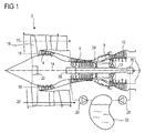
- the figure 1 represents in simplified manner an axial turbomachine. It is in this case a double-flow turbojet engine.
- the turbojet engine 2 comprises a first compression level, called a low-pressure compressor 4, a second compression level, called a high-pressure compressor 6, a combustion chamber 8 and one or more levels of turbines 10.
- a first compression level called a low-pressure compressor 4
- a second compression level called a high-pressure compressor 6
- a combustion chamber 8 and one or more levels of turbines 10.
- the mechanical power of the turbine 10 transmitted via the central shaft to the rotor 12 sets in motion the two compressors 4 and 6.
- the latter comprise several rows of rotor blades associated with rows of stator vanes.
- the rotation of the rotor about its axis of rotation 14 thus makes it possible to generate an air flow and to compress it progressively until the arrival of the combustion chamber 8.
- a fan commonly referred fan or fan 16 is coupled to the rotor 12 and generates a flow of air which is divided into a primary flow 18 through the various levels mentioned above of the turbomachine, and a secondary flow 20 through an annular conduit (partially shown) along the machine to then join the primary flow at the turbine outlet.
- Reducing means such as an epicyclic reduction gearbox 22, can reduce the rotational speed of the fan 16 and / or the low-pressure compressor 4 relative to the associated turbine 10.
- the secondary stream 20 can be accelerated to generate a thrust reaction.
- the primary 18 and secondary 20 streams are radially concentric ring flows. Their progressive circulation becomes permitted thanks to several rotors 12 with independent trees 24. These shafts 24 can be coaxial and fitted into one another. They are rotatable via bearings 26 at their interfaces with the casing of the turbomachine 2, or even with bearings at their common interfaces.
- Cooling and / or lubrication of the bearings 26 and the optional epicyclic reduction gear 22 are provided by an oil circuit, possibly closed.
- the latter can also supply actuators such as cylinders (not shown).
- the oil circuit may also include a heat exchanger (not shown) for cooling the oil.
- the bearings 26 are arranged in chambers, generally sealed by means of joints around the shafts, where they are sprayed with oil. In contact with the bearings 26, the oil is charged with air, so that the oil recovered has become a liquid air-oil mixture, for example with at least 1% by volume of air.
- the chambers possibly forming dry housings, are provided with suction orifices, also called drainage holes, in communication with pumps 28.
- the pumps 28 may be of the volumetric pump type, for example to control the flow rate.
- the oil circuit may thus comprise several oil recovery lines converging towards a tank 30, possibly main.
- the tank 30 is also the starting point of several feed lines (not shown) of the bearings 26 and various equipment.
- the tank 30 can be attached to the nacelle of the turbomachine. It can be placed between two annular walls guiding concentric flows; for example the secondary flow 20 and the flow surrounding the turbomachine, or the primary flow 18 and the secondary flow 20.
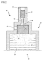
- the figure 2 is a sectional view of an upper portion of an oil reservoir such as that of figure 1 .
- the reservoir 30 is partially filled, its lower portion 32 contains a liquid air-oil mixture 34, and the upper portion 36 contains a predominantly gaseous phase in which suspended oil droplets remain.
- the reservoir 30 forms an enclosure 38, such as a receptacle with a volume useful for containing oil.
- the reservoir 30 is provided with a deaerator device 40 for separating the air from the combined oil in the mixture 34.
- the inlet 42 of the air-oil mixture 34 can be made tangentially to the inner surface of the enclosure 38.
- the admission speed of the mixture 34 in the chamber 38 generates a rotational movement of the amount of oil already present in the enclosure 38.
- a vortex is created, and the gas interface -liquid becomes parabolic.
- the air bubbles of the mixture 34 tend to regain the interface.
- the oil depleted in air becomes denser and is concentrated in the lower part of the enclosure, against the wall of the latter.
- the homogeneous oil is removed for use in oil circuit equipment.
- the tank 30 comprises a vent 44. This can be occupied by the deaeration device 40.
- the communication between the enclosure 38 and the vent 44 can be performed via the deaeration device 40.
- the vent 44 comprises a rotor 46. Its axis of rotation can be in the direction of circulation of the air leaving the tank 30 via the vent 44.
- the rotor 46 may comprise a driven portion 48 receiving at least a portion of the kinetic energy of the air-oil mixture 34 at the inlet 42. This driven portion benefits from the dynamic pressure of the mixture, and allows the rotational movement of the rotor .
- the driven portion 48 converts the movement of the mixture 34 into a rotational movement of the rotor 46.
- the driven portion 48 may be of foam. It may be a disk with an annular row of blades or buckets that receive and capture the energy of the flow of the mixture 34.
- the passage section of the inlet 42 may be calibrated to drive the rotor 46 at a predetermined rotational speed.
- the arrival is equipped with a module reducing its passage section to accelerate the admission speed of the mixture, and thus to control the speed of rotation of the rotor.
- the driven portion 48 may be disposed in a dedicated pocket of the enclosure 38; the inner surface of the pocket may generally fit the driven portion 48.
- the inlet 42 of the mixture 34 may open into the pocket so as to meet the driven portion 48 by actuating it.
- the rotor 46 may comprise a filtering portion 50, for example disposed in the vent 44 or at the inlet of the vent.
- the filtering portion 50 may comprise foam, possibly metallic. The communicating meshes of the foam allow the air of deaeration to cross the rotor 46, and to escape via the vent 44.
- the filtering portion 50 is connected to the driven portion 48 via a rod 52 mounted to be rotatable by relative to the wall of the tank 30, and in particular of the duct of the vent 44.
- the rotational movement of the filtering portion 50 allows several actions. It makes it possible to extract by centrifugation the oil that the filtering portion 50 has captured, and to project this oil against the internal surface of the vent 44. In the normal direction of assembly, the oil projected on the inner surface falls back the conduit by gravitation in the chamber 38 and adds to the volume of oil that is already present.
- the rotational movement causes The deaeration air is also rotated, so that the suspended droplets agglutinate on the internal surface of the vent duct. This is also the result of centrifugal force; which precedes the gravity allowing the return of the oil in the chamber 38 below. Note that the driven portion can contribute to the rotation of the air in the vent 44.
- the inner surface of the duct of the vent 44 is opposite the rotor 46 and surrounds it. It can be smooth, or be lined with foam capturing oil droplets all around the rotor. The oil which is collected there can then flow to return to the enclosure 38.
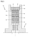
- the figure 3 represents an upper portion of the tank 130 with a de-aerating device 140 according to a second embodiment of the invention. This figure 3 resumes the numbering of the preceding figures for identical or similar elements, however, the numbering is incremented by 100. Specific numbers are used for the specific elements of this embodiment.
- the rotor 146 comprises several disks 154 stirring the air in the vent 144. They rotate the air passing through the vent 144.
- the disks 154 can be made of foam. They can be distant from each other. Static layers (156; 158) of foam may be interposed between the disks 154 of the rotor 144, for example so as to form an alternation of layers (156; 158) and disks 154.
- the vent 144 may present an outlet layer 158 forming a porous plug capturing the droplets.
- the invention has been presented in connection with a reservoir provided with a de-aerating device.
- a rotor can be placed in a passage connecting the arrival to the vent, without the chamber of the tank directly promotes a deaeration.
- the de-aerating device can also be an isolated equipment, remote from the tank.
- the deaerator device can be integrated in the heat exchanger, for example its collector can form an enclosure. It can be integrated with a pump.
- the rotor comprises a driven portion which is introduced into the arrival or which is in front of the finish.
- the vent may be in the extension of the rotor, and therefore in the extension of the arrival.
- both the rotor and the vent may be horizontal or substantially inclined relative to the horizontal.
- An inclined chute may be added for the gravitational return of the oil into the enclosure.
- the vent may be offset relative to the axis of rotation of the rotor.
- the rotor may be outside the vent.
- the driving portion may be arranged to be partially in contact with the parabolic interface between the liquid and the gas.
Landscapes
- Engineering & Computer Science (AREA)
- Chemical & Material Sciences (AREA)
- Chemical Kinetics & Catalysis (AREA)
- General Engineering & Computer Science (AREA)
- Mechanical Engineering (AREA)
- Combustion & Propulsion (AREA)
- Dispersion Chemistry (AREA)
- Physics & Mathematics (AREA)
- Fluid Mechanics (AREA)
- Lubrication Details And Ventilation Of Internal Combustion Engines (AREA)
Applications Claiming Priority (1)
| Application Number | Priority Date | Filing Date | Title |
|---|---|---|---|
| BE2015/5611A BE1023483B1 (fr) | 2015-10-02 | 2015-10-02 | Reservoir d'huile de turbomachine avec desaerateur |
Publications (2)
| Publication Number | Publication Date |
|---|---|
| EP3150265A1 true EP3150265A1 (de) | 2017-04-05 |
| EP3150265B1 EP3150265B1 (de) | 2018-12-12 |
Family
ID=54293006
Family Applications (1)
| Application Number | Title | Priority Date | Filing Date |
|---|---|---|---|
| EP16190529.4A Active EP3150265B1 (de) | 2015-10-02 | 2016-09-26 | Öltank einer turbomaschine mit entlüfter |
Country Status (4)
| Country | Link |
|---|---|
| US (1) | US20170096910A1 (de) |
| EP (1) | EP3150265B1 (de) |
| CN (1) | CN106968795B (de) |
| BE (1) | BE1023483B1 (de) |
Cited By (4)
| Publication number | Priority date | Publication date | Assignee | Title |
|---|---|---|---|---|
| CN111107923A (zh) * | 2017-09-26 | 2020-05-05 | 赛峰直升机发动机公司 | 涡轮机离心式通气器构件和用于制造所述构件的方法 |
| FR3095766A1 (fr) | 2019-05-10 | 2020-11-13 | Safran Aircraft Engines | Dispositif de drainage continu dans un circuit de lubrification comprenant un réservoir de stockage |
| WO2021209456A1 (fr) | 2020-04-14 | 2021-10-21 | Safran Aero Boosters Sa | Surveillance de l'huile d'un dispositif de lubrification |
| WO2023041585A1 (fr) | 2021-09-14 | 2023-03-23 | Safran Aero Boosters Sa | Dispositif désaérateur d'huile avec reservoir pourvu d'une paroi de stabilisation |
Families Citing this family (29)
| Publication number | Priority date | Publication date | Assignee | Title |
|---|---|---|---|---|
| US11504651B2 (en) * | 2017-12-20 | 2022-11-22 | Massachusetts Institute Of Technology | Foam reduction and/or prevention methods and associated systems and articles |
| EP3818258B1 (de) * | 2018-07-05 | 2023-01-04 | Safran | Teil für zentrifugalentlüfter einer turbomaschine mit einem filtergitter |
| US11577852B2 (en) | 2018-11-02 | 2023-02-14 | General Electric Company | Fuel oxygen conversion unit |
| US11085636B2 (en) | 2018-11-02 | 2021-08-10 | General Electric Company | Fuel oxygen conversion unit |
| US11148824B2 (en) | 2018-11-02 | 2021-10-19 | General Electric Company | Fuel delivery system having a fuel oxygen reduction unit |
| US11447263B2 (en) | 2018-11-02 | 2022-09-20 | General Electric Company | Fuel oxygen reduction unit control system |
| US11161622B2 (en) | 2018-11-02 | 2021-11-02 | General Electric Company | Fuel oxygen reduction unit |
| US11319085B2 (en) | 2018-11-02 | 2022-05-03 | General Electric Company | Fuel oxygen conversion unit with valve control |
| US11186382B2 (en) | 2018-11-02 | 2021-11-30 | General Electric Company | Fuel oxygen conversion unit |
| US11851204B2 (en) | 2018-11-02 | 2023-12-26 | General Electric Company | Fuel oxygen conversion unit with a dual separator pump |
| US11193671B2 (en) | 2018-11-02 | 2021-12-07 | General Electric Company | Fuel oxygen conversion unit with a fuel gas separator |
| US11420763B2 (en) | 2018-11-02 | 2022-08-23 | General Electric Company | Fuel delivery system having a fuel oxygen reduction unit |
| US11131256B2 (en) | 2018-11-02 | 2021-09-28 | General Electric Company | Fuel oxygen conversion unit with a fuel/gas separator |
| US11391211B2 (en) | 2018-11-28 | 2022-07-19 | General Electric Company | Waste heat recovery system |
| US11015534B2 (en) | 2018-11-28 | 2021-05-25 | General Electric Company | Thermal management system |
| US10914274B1 (en) | 2019-09-11 | 2021-02-09 | General Electric Company | Fuel oxygen reduction unit with plasma reactor |
| US11774427B2 (en) | 2019-11-27 | 2023-10-03 | General Electric Company | Methods and apparatus for monitoring health of fuel oxygen conversion unit |
| US11906163B2 (en) | 2020-05-01 | 2024-02-20 | General Electric Company | Fuel oxygen conversion unit with integrated water removal |
| US11866182B2 (en) | 2020-05-01 | 2024-01-09 | General Electric Company | Fuel delivery system having a fuel oxygen reduction unit |
| US11773776B2 (en) | 2020-05-01 | 2023-10-03 | General Electric Company | Fuel oxygen reduction unit for prescribed operating conditions |
| US11434824B2 (en) | 2021-02-03 | 2022-09-06 | General Electric Company | Fuel heater and energy conversion system |
| US11591965B2 (en) | 2021-03-29 | 2023-02-28 | General Electric Company | Thermal management system for transferring heat between fluids |
| US12139270B2 (en) | 2021-04-19 | 2024-11-12 | General Electric Company | Aircraft thermal transport system and method |
| US12115470B2 (en) | 2021-04-27 | 2024-10-15 | General Electric Company | Fuel oxygen reduction unit |
| US12005377B2 (en) | 2021-06-15 | 2024-06-11 | General Electric Company | Fuel oxygen reduction unit with level control device |
| US11542870B1 (en) | 2021-11-24 | 2023-01-03 | General Electric Company | Gas supply system |
| US12060832B1 (en) * | 2023-03-16 | 2024-08-13 | Pratt & Whitney Canada Corp. | Aircraft engine fluid system with shut-off valve |
| CN117160062A (zh) * | 2023-11-01 | 2023-12-05 | 南通金泽油脂有限公司 | 一种工业级混合油蒸馏塔 |
| WO2026077713A1 (fr) * | 2024-10-10 | 2026-04-16 | Safran Aero Boosters | Désaérateur incurvé installé dans un reservoir d'huile pour turbomachine |
Citations (6)
| Publication number | Priority date | Publication date | Assignee | Title |
|---|---|---|---|---|
| FR2054388A5 (de) * | 1969-07-22 | 1971-04-16 | Loewe Pumpenfabrik Gmbh | |
| EP0400202A2 (de) * | 1989-05-30 | 1990-12-05 | Mitsubishi Oil Company, Limited | Vorrichtung zur Entfernung von Gasen aus Flüssigkeiten |
| EP0404647A1 (de) * | 1989-06-21 | 1990-12-27 | E & M LAMORT | Vorrichtung zur Flüssigkeitsentgasung |
| US5254145A (en) * | 1992-02-19 | 1993-10-19 | Societe Nationale D'etude Et De Construction De Moteurs D'aviation "S.N.E.C.M.A." | Centrifugal oil de-aerator |
| EP1297875A1 (de) | 2001-09-27 | 2003-04-02 | Techspace Aero S.A. | Statische Entgasungsvorrichtung mit gleichbleibendem Flüssigkeitsstand |
| EP2199614A1 (de) * | 2008-12-22 | 2010-06-23 | Techspace Aero S.A. | Kombinierte Pump- und Abscheidemaschine für Ölkreislauf eines Turbostrahltriebwerks |
Family Cites Families (5)
| Publication number | Priority date | Publication date | Assignee | Title |
|---|---|---|---|---|
| US3447290A (en) * | 1967-09-18 | 1969-06-03 | Frick Co | Separator for disentrainment of material from a gaseous fluid stream |
| US4922691A (en) * | 1988-09-12 | 1990-05-08 | Shen Hsin Der | Separator of vaporizing oil and smoke |
| JPH061710U (ja) * | 1992-06-09 | 1994-01-14 | 三菱重工業株式会社 | エンジン潤滑オイル用気泡分離装置 |
| SE533471C2 (sv) * | 2009-02-05 | 2010-10-05 | Alfa Laval Corp Ab | Anläggning för avskiljning av olja från en gasblandning samt förfarande för avskiljning av olja från en gasblandning |
| US9765644B2 (en) * | 2015-01-20 | 2017-09-19 | United Technologies Corporation | Deoiler debris baffle |
-
2015
- 2015-10-02 BE BE2015/5611A patent/BE1023483B1/fr active
-
2016
- 2016-09-26 EP EP16190529.4A patent/EP3150265B1/de active Active
- 2016-09-29 CN CN201610865433.2A patent/CN106968795B/zh active Active
- 2016-09-30 US US15/281,716 patent/US20170096910A1/en not_active Abandoned
Patent Citations (6)
| Publication number | Priority date | Publication date | Assignee | Title |
|---|---|---|---|---|
| FR2054388A5 (de) * | 1969-07-22 | 1971-04-16 | Loewe Pumpenfabrik Gmbh | |
| EP0400202A2 (de) * | 1989-05-30 | 1990-12-05 | Mitsubishi Oil Company, Limited | Vorrichtung zur Entfernung von Gasen aus Flüssigkeiten |
| EP0404647A1 (de) * | 1989-06-21 | 1990-12-27 | E & M LAMORT | Vorrichtung zur Flüssigkeitsentgasung |
| US5254145A (en) * | 1992-02-19 | 1993-10-19 | Societe Nationale D'etude Et De Construction De Moteurs D'aviation "S.N.E.C.M.A." | Centrifugal oil de-aerator |
| EP1297875A1 (de) | 2001-09-27 | 2003-04-02 | Techspace Aero S.A. | Statische Entgasungsvorrichtung mit gleichbleibendem Flüssigkeitsstand |
| EP2199614A1 (de) * | 2008-12-22 | 2010-06-23 | Techspace Aero S.A. | Kombinierte Pump- und Abscheidemaschine für Ölkreislauf eines Turbostrahltriebwerks |
Cited By (6)
| Publication number | Priority date | Publication date | Assignee | Title |
|---|---|---|---|---|
| CN111107923A (zh) * | 2017-09-26 | 2020-05-05 | 赛峰直升机发动机公司 | 涡轮机离心式通气器构件和用于制造所述构件的方法 |
| FR3095766A1 (fr) | 2019-05-10 | 2020-11-13 | Safran Aircraft Engines | Dispositif de drainage continu dans un circuit de lubrification comprenant un réservoir de stockage |
| WO2021209456A1 (fr) | 2020-04-14 | 2021-10-21 | Safran Aero Boosters Sa | Surveillance de l'huile d'un dispositif de lubrification |
| BE1028211A1 (fr) | 2020-04-14 | 2021-11-09 | Safran Aero Boosters | Surveillance de l'huile d'un dispositif de lubrification |
| WO2023041585A1 (fr) | 2021-09-14 | 2023-03-23 | Safran Aero Boosters Sa | Dispositif désaérateur d'huile avec reservoir pourvu d'une paroi de stabilisation |
| BE1029751A1 (fr) | 2021-09-14 | 2023-04-05 | Safran Aero Boosters | Dispositif désaérateur d’huile avec reservoir pourvu d’une paroi de stabilisation |
Also Published As
| Publication number | Publication date |
|---|---|
| CN106968795A (zh) | 2017-07-21 |
| EP3150265B1 (de) | 2018-12-12 |
| US20170096910A1 (en) | 2017-04-06 |
| BE1023483B1 (fr) | 2017-04-05 |
| BE1023483A1 (fr) | 2017-04-05 |
| CN106968795B (zh) | 2020-02-21 |
Similar Documents
| Publication | Publication Date | Title |
|---|---|---|
| EP3150265B1 (de) | Öltank einer turbomaschine mit entlüfter | |
| EP2199614B1 (de) | Kombinierte Pump- und Abscheidemaschine für Ölkreislauf eines Turbostrahltriebwerks | |
| EP3155234B1 (de) | Turbinenmotor mit einem antriebssystem für eine vorrichtung wie ein hilfsaggregatgehäuse | |
| EP3669964B1 (de) | Vorrichtung zum trennen eines luft-öl-gemisches | |
| EP2826709B1 (de) | Modulare Antriebsanlage und Luftfahrzeug mit einem Auftriebsrotor | |
| FR3110194A1 (fr) | Turbomachine d’aeronef comprenant un dispositif de lubrification d’un palier | |
| CA2874707A1 (fr) | Palier a moyen de lubrification et systeme pour changer le pas des pales d'une helice de turbopropulseur d'aeronef, equipe dudit palier | |
| FR2471813A1 (fr) | Dispositif de traitement de fluide | |
| SE1550684A1 (sv) | Apparatus for cleaning crank case gases | |
| FR3090035A1 (fr) | Dispositif de deshuilage et d’etancheite d’une enceinte de lubrification de turbomachine | |
| EP4296476B1 (de) | Öltank für eine g-negativ kompatible turbomaschine mit zyklonabscheider | |
| EP4408738B1 (de) | Modul für ein flugzeugturbinentriebwerk | |
| EP4569214A1 (de) | Flugzeugturbinentriebwerk | |
| FR3086974A1 (fr) | Boitier d'engrenages de turbomachine | |
| WO2023247846A1 (fr) | Reservoir d'huile pour turbomachine avec compartiment inférieur avec conduit de sortie d'huile compatible g négatif | |
| EP3131656B1 (de) | Filtrierung eines stroms aus gas/partikeln | |
| WO2025242590A1 (fr) | Sortie de dégazage pour une enceinte de palier de turbomachine d'aéronef et son procédé d'utilisation | |
| FR3100843A1 (fr) | Support de palier de turbomachine à récupération d’huile améliorée | |
| FR3163697A1 (fr) | Turbomachine comprenant une enceinte de lubrification et un reducteur de vitesse | |
| WO2026077713A1 (fr) | Désaérateur incurvé installé dans un reservoir d'huile pour turbomachine | |
| EP4296474A1 (de) | Öltank für eine turbomaschine mit einem negativ kompatiblen zentrifugalrad | |
| FR3013075A1 (fr) | Systeme d'alimentation en huile par pompe a jet | |
| FR3148258A1 (fr) | Carter pour une turbomachine d’aeronef |
Legal Events
| Date | Code | Title | Description |
|---|---|---|---|
| PUAI | Public reference made under article 153(3) epc to a published international application that has entered the european phase |
Free format text: ORIGINAL CODE: 0009012 |
|
| STAA | Information on the status of an ep patent application or granted ep patent |
Free format text: STATUS: THE APPLICATION HAS BEEN PUBLISHED |
|
| AK | Designated contracting states |
Kind code of ref document: A1 Designated state(s): AL AT BE BG CH CY CZ DE DK EE ES FI FR GB GR HR HU IE IS IT LI LT LU LV MC MK MT NL NO PL PT RO RS SE SI SK SM TR |
|
| AX | Request for extension of the european patent |
Extension state: BA ME |
|
| STAA | Information on the status of an ep patent application or granted ep patent |
Free format text: STATUS: REQUEST FOR EXAMINATION WAS MADE |
|
| 17P | Request for examination filed |
Effective date: 20171004 |
|
| RBV | Designated contracting states (corrected) |
Designated state(s): AL AT BE BG CH CY CZ DE DK EE ES FI FR GB GR HR HU IE IS IT LI LT LU LV MC MK MT NL NO PL PT RO RS SE SI SK SM TR |
|
| STAA | Information on the status of an ep patent application or granted ep patent |
Free format text: STATUS: EXAMINATION IS IN PROGRESS |
|
| 17Q | First examination report despatched |
Effective date: 20171116 |
|
| GRAP | Despatch of communication of intention to grant a patent |
Free format text: ORIGINAL CODE: EPIDOSNIGR1 |
|
| STAA | Information on the status of an ep patent application or granted ep patent |
Free format text: STATUS: GRANT OF PATENT IS INTENDED |
|
| INTG | Intention to grant announced |
Effective date: 20180615 |
|
| GRAS | Grant fee paid |
Free format text: ORIGINAL CODE: EPIDOSNIGR3 |
|
| GRAA | (expected) grant |
Free format text: ORIGINAL CODE: 0009210 |
|
| STAA | Information on the status of an ep patent application or granted ep patent |
Free format text: STATUS: THE PATENT HAS BEEN GRANTED |
|
| AK | Designated contracting states |
Kind code of ref document: B1 Designated state(s): AL AT BE BG CH CY CZ DE DK EE ES FI FR GB GR HR HU IE IS IT LI LT LU LV MC MK MT NL NO PL PT RO RS SE SI SK SM TR |
|
| REG | Reference to a national code |
Ref country code: GB Ref legal event code: FG4D Free format text: NOT ENGLISH |
|
| REG | Reference to a national code |
Ref country code: CH Ref legal event code: EP |
|
| REG | Reference to a national code |
Ref country code: AT Ref legal event code: REF Ref document number: 1075202 Country of ref document: AT Kind code of ref document: T Effective date: 20181215 |
|
| REG | Reference to a national code |
Ref country code: DE Ref legal event code: R096 Ref document number: 602016008065 Country of ref document: DE |
|
| REG | Reference to a national code |
Ref country code: IE Ref legal event code: FG4D Free format text: LANGUAGE OF EP DOCUMENT: FRENCH |
|
| REG | Reference to a national code |
Ref country code: NL Ref legal event code: MP Effective date: 20181212 |
|
| REG | Reference to a national code |
Ref country code: LT Ref legal event code: MG4D |
|
| PG25 | Lapsed in a contracting state [announced via postgrant information from national office to epo] |
Ref country code: ES Free format text: LAPSE BECAUSE OF FAILURE TO SUBMIT A TRANSLATION OF THE DESCRIPTION OR TO PAY THE FEE WITHIN THE PRESCRIBED TIME-LIMIT Effective date: 20181212 Ref country code: LV Free format text: LAPSE BECAUSE OF FAILURE TO SUBMIT A TRANSLATION OF THE DESCRIPTION OR TO PAY THE FEE WITHIN THE PRESCRIBED TIME-LIMIT Effective date: 20181212 Ref country code: HR Free format text: LAPSE BECAUSE OF FAILURE TO SUBMIT A TRANSLATION OF THE DESCRIPTION OR TO PAY THE FEE WITHIN THE PRESCRIBED TIME-LIMIT Effective date: 20181212 Ref country code: NO Free format text: LAPSE BECAUSE OF FAILURE TO SUBMIT A TRANSLATION OF THE DESCRIPTION OR TO PAY THE FEE WITHIN THE PRESCRIBED TIME-LIMIT Effective date: 20190312 Ref country code: BG Free format text: LAPSE BECAUSE OF FAILURE TO SUBMIT A TRANSLATION OF THE DESCRIPTION OR TO PAY THE FEE WITHIN THE PRESCRIBED TIME-LIMIT Effective date: 20190312 Ref country code: FI Free format text: LAPSE BECAUSE OF FAILURE TO SUBMIT A TRANSLATION OF THE DESCRIPTION OR TO PAY THE FEE WITHIN THE PRESCRIBED TIME-LIMIT Effective date: 20181212 Ref country code: LT Free format text: LAPSE BECAUSE OF FAILURE TO SUBMIT A TRANSLATION OF THE DESCRIPTION OR TO PAY THE FEE WITHIN THE PRESCRIBED TIME-LIMIT Effective date: 20181212 |
|
| REG | Reference to a national code |
Ref country code: AT Ref legal event code: MK05 Ref document number: 1075202 Country of ref document: AT Kind code of ref document: T Effective date: 20181212 |
|
| PG25 | Lapsed in a contracting state [announced via postgrant information from national office to epo] |
Ref country code: SE Free format text: LAPSE BECAUSE OF FAILURE TO SUBMIT A TRANSLATION OF THE DESCRIPTION OR TO PAY THE FEE WITHIN THE PRESCRIBED TIME-LIMIT Effective date: 20181212 Ref country code: RS Free format text: LAPSE BECAUSE OF FAILURE TO SUBMIT A TRANSLATION OF THE DESCRIPTION OR TO PAY THE FEE WITHIN THE PRESCRIBED TIME-LIMIT Effective date: 20181212 Ref country code: GR Free format text: LAPSE BECAUSE OF FAILURE TO SUBMIT A TRANSLATION OF THE DESCRIPTION OR TO PAY THE FEE WITHIN THE PRESCRIBED TIME-LIMIT Effective date: 20190313 Ref country code: AL Free format text: LAPSE BECAUSE OF FAILURE TO SUBMIT A TRANSLATION OF THE DESCRIPTION OR TO PAY THE FEE WITHIN THE PRESCRIBED TIME-LIMIT Effective date: 20181212 |
|
| PG25 | Lapsed in a contracting state [announced via postgrant information from national office to epo] |
Ref country code: NL Free format text: LAPSE BECAUSE OF FAILURE TO SUBMIT A TRANSLATION OF THE DESCRIPTION OR TO PAY THE FEE WITHIN THE PRESCRIBED TIME-LIMIT Effective date: 20181212 |
|
| PG25 | Lapsed in a contracting state [announced via postgrant information from national office to epo] |
Ref country code: PT Free format text: LAPSE BECAUSE OF FAILURE TO SUBMIT A TRANSLATION OF THE DESCRIPTION OR TO PAY THE FEE WITHIN THE PRESCRIBED TIME-LIMIT Effective date: 20190412 Ref country code: CZ Free format text: LAPSE BECAUSE OF FAILURE TO SUBMIT A TRANSLATION OF THE DESCRIPTION OR TO PAY THE FEE WITHIN THE PRESCRIBED TIME-LIMIT Effective date: 20181212 Ref country code: IT Free format text: LAPSE BECAUSE OF FAILURE TO SUBMIT A TRANSLATION OF THE DESCRIPTION OR TO PAY THE FEE WITHIN THE PRESCRIBED TIME-LIMIT Effective date: 20181212 Ref country code: PL Free format text: LAPSE BECAUSE OF FAILURE TO SUBMIT A TRANSLATION OF THE DESCRIPTION OR TO PAY THE FEE WITHIN THE PRESCRIBED TIME-LIMIT Effective date: 20181212 |
|
| PG25 | Lapsed in a contracting state [announced via postgrant information from national office to epo] |
Ref country code: IS Free format text: LAPSE BECAUSE OF FAILURE TO SUBMIT A TRANSLATION OF THE DESCRIPTION OR TO PAY THE FEE WITHIN THE PRESCRIBED TIME-LIMIT Effective date: 20190412 Ref country code: SM Free format text: LAPSE BECAUSE OF FAILURE TO SUBMIT A TRANSLATION OF THE DESCRIPTION OR TO PAY THE FEE WITHIN THE PRESCRIBED TIME-LIMIT Effective date: 20181212 Ref country code: SK Free format text: LAPSE BECAUSE OF FAILURE TO SUBMIT A TRANSLATION OF THE DESCRIPTION OR TO PAY THE FEE WITHIN THE PRESCRIBED TIME-LIMIT Effective date: 20181212 Ref country code: EE Free format text: LAPSE BECAUSE OF FAILURE TO SUBMIT A TRANSLATION OF THE DESCRIPTION OR TO PAY THE FEE WITHIN THE PRESCRIBED TIME-LIMIT Effective date: 20181212 Ref country code: RO Free format text: LAPSE BECAUSE OF FAILURE TO SUBMIT A TRANSLATION OF THE DESCRIPTION OR TO PAY THE FEE WITHIN THE PRESCRIBED TIME-LIMIT Effective date: 20181212 |
|
| REG | Reference to a national code |
Ref country code: DE Ref legal event code: R026 Ref document number: 602016008065 Country of ref document: DE |
|
| PLBI | Opposition filed |
Free format text: ORIGINAL CODE: 0009260 |
|
| PLAX | Notice of opposition and request to file observation + time limit sent |
Free format text: ORIGINAL CODE: EPIDOSNOBS2 |
|
| 26 | Opposition filed |
Opponent name: UNITED TECHNOLOGIES CORPORATION Effective date: 20190912 |
|
| PG25 | Lapsed in a contracting state [announced via postgrant information from national office to epo] |
Ref country code: SI Free format text: LAPSE BECAUSE OF FAILURE TO SUBMIT A TRANSLATION OF THE DESCRIPTION OR TO PAY THE FEE WITHIN THE PRESCRIBED TIME-LIMIT Effective date: 20181212 Ref country code: AT Free format text: LAPSE BECAUSE OF FAILURE TO SUBMIT A TRANSLATION OF THE DESCRIPTION OR TO PAY THE FEE WITHIN THE PRESCRIBED TIME-LIMIT Effective date: 20181212 Ref country code: DK Free format text: LAPSE BECAUSE OF FAILURE TO SUBMIT A TRANSLATION OF THE DESCRIPTION OR TO PAY THE FEE WITHIN THE PRESCRIBED TIME-LIMIT Effective date: 20181212 |
|
| PLBB | Reply of patent proprietor to notice(s) of opposition received |
Free format text: ORIGINAL CODE: EPIDOSNOBS3 |
|
| PG25 | Lapsed in a contracting state [announced via postgrant information from national office to epo] |
Ref country code: TR Free format text: LAPSE BECAUSE OF FAILURE TO SUBMIT A TRANSLATION OF THE DESCRIPTION OR TO PAY THE FEE WITHIN THE PRESCRIBED TIME-LIMIT Effective date: 20181212 |
|
| PG25 | Lapsed in a contracting state [announced via postgrant information from national office to epo] |
Ref country code: MC Free format text: LAPSE BECAUSE OF FAILURE TO SUBMIT A TRANSLATION OF THE DESCRIPTION OR TO PAY THE FEE WITHIN THE PRESCRIBED TIME-LIMIT Effective date: 20181212 |
|
| REG | Reference to a national code |
Ref country code: CH Ref legal event code: PL |
|
| PG25 | Lapsed in a contracting state [announced via postgrant information from national office to epo] |
Ref country code: LU Free format text: LAPSE BECAUSE OF NON-PAYMENT OF DUE FEES Effective date: 20190926 Ref country code: CH Free format text: LAPSE BECAUSE OF NON-PAYMENT OF DUE FEES Effective date: 20190930 Ref country code: IE Free format text: LAPSE BECAUSE OF NON-PAYMENT OF DUE FEES Effective date: 20190926 Ref country code: LI Free format text: LAPSE BECAUSE OF NON-PAYMENT OF DUE FEES Effective date: 20190930 |
|
| PLAB | Opposition data, opponent's data or that of the opponent's representative modified |
Free format text: ORIGINAL CODE: 0009299OPPO |
|
| R26 | Opposition filed (corrected) |
Opponent name: RAYTHEON TECHNOLOGIES CORPORATION Effective date: 20190912 |
|
| REG | Reference to a national code |
Ref country code: DE Ref legal event code: R100 Ref document number: 602016008065 Country of ref document: DE |
|
| PLCK | Communication despatched that opposition was rejected |
Free format text: ORIGINAL CODE: EPIDOSNREJ1 |
|
| PG25 | Lapsed in a contracting state [announced via postgrant information from national office to epo] |
Ref country code: CY Free format text: LAPSE BECAUSE OF FAILURE TO SUBMIT A TRANSLATION OF THE DESCRIPTION OR TO PAY THE FEE WITHIN THE PRESCRIBED TIME-LIMIT Effective date: 20181212 |
|
| PLBN | Opposition rejected |
Free format text: ORIGINAL CODE: 0009273 |
|
| STAA | Information on the status of an ep patent application or granted ep patent |
Free format text: STATUS: OPPOSITION REJECTED |
|
| PG25 | Lapsed in a contracting state [announced via postgrant information from national office to epo] |
Ref country code: MT Free format text: LAPSE BECAUSE OF FAILURE TO SUBMIT A TRANSLATION OF THE DESCRIPTION OR TO PAY THE FEE WITHIN THE PRESCRIBED TIME-LIMIT Effective date: 20181212 Ref country code: HU Free format text: LAPSE BECAUSE OF FAILURE TO SUBMIT A TRANSLATION OF THE DESCRIPTION OR TO PAY THE FEE WITHIN THE PRESCRIBED TIME-LIMIT; INVALID AB INITIO Effective date: 20160926 |
|
| 27O | Opposition rejected |
Effective date: 20210128 |
|
| PG25 | Lapsed in a contracting state [announced via postgrant information from national office to epo] |
Ref country code: MK Free format text: LAPSE BECAUSE OF FAILURE TO SUBMIT A TRANSLATION OF THE DESCRIPTION OR TO PAY THE FEE WITHIN THE PRESCRIBED TIME-LIMIT Effective date: 20181212 |
|
| PGFP | Annual fee paid to national office [announced via postgrant information from national office to epo] |
Ref country code: DE Payment date: 20250919 Year of fee payment: 10 |
|
| PGFP | Annual fee paid to national office [announced via postgrant information from national office to epo] |
Ref country code: BE Payment date: 20250919 Year of fee payment: 10 Ref country code: GB Payment date: 20250923 Year of fee payment: 10 |
|
| PGFP | Annual fee paid to national office [announced via postgrant information from national office to epo] |
Ref country code: FR Payment date: 20250924 Year of fee payment: 10 |