EP3155444B1 - Procédé de localisation d'un objet avec un radar fmcw - Google Patents
Procédé de localisation d'un objet avec un radar fmcw Download PDFInfo
- Publication number
- EP3155444B1 EP3155444B1 EP15722979.0A EP15722979A EP3155444B1 EP 3155444 B1 EP3155444 B1 EP 3155444B1 EP 15722979 A EP15722979 A EP 15722979A EP 3155444 B1 EP3155444 B1 EP 3155444B1
- Authority
- EP
- European Patent Office
- Prior art keywords
- ramp
- time
- ramps
- radar
- frequency
- Prior art date
- Legal status (The legal status is an assumption and is not a legal conclusion. Google has not performed a legal analysis and makes no representation as to the accuracy of the status listed.)
- Active
Links
Images




Classifications
-
- G—PHYSICS
- G01—MEASURING; TESTING
- G01S—RADIO DIRECTION-FINDING; RADIO NAVIGATION; DETERMINING DISTANCE OR VELOCITY BY USE OF RADIO WAVES; LOCATING OR PRESENCE-DETECTING BY USE OF THE REFLECTION OR RERADIATION OF RADIO WAVES; ANALOGOUS ARRANGEMENTS USING OTHER WAVES
- G01S13/00—Systems using the reflection or reradiation of radio waves, e.g. radar systems; Analogous systems using reflection or reradiation of waves whose nature or wavelength is irrelevant or unspecified
- G01S13/02—Systems using reflection of radio waves, e.g. primary radar systems; Analogous systems
- G01S13/06—Systems determining position data of a target
- G01S13/42—Simultaneous measurement of distance and other co-ordinates
-
- G—PHYSICS
- G01—MEASURING; TESTING
- G01S—RADIO DIRECTION-FINDING; RADIO NAVIGATION; DETERMINING DISTANCE OR VELOCITY BY USE OF RADIO WAVES; LOCATING OR PRESENCE-DETECTING BY USE OF THE REFLECTION OR RERADIATION OF RADIO WAVES; ANALOGOUS ARRANGEMENTS USING OTHER WAVES
- G01S7/00—Details of systems according to groups G01S13/00, G01S15/00, G01S17/00
- G01S7/02—Details of systems according to groups G01S13/00, G01S15/00, G01S17/00 of systems according to group G01S13/00
- G01S7/35—Details of non-pulse systems
- G01S7/352—Receivers
- G01S7/354—Extracting wanted echo-signals
-
- G—PHYSICS
- G01—MEASURING; TESTING
- G01S—RADIO DIRECTION-FINDING; RADIO NAVIGATION; DETERMINING DISTANCE OR VELOCITY BY USE OF RADIO WAVES; LOCATING OR PRESENCE-DETECTING BY USE OF THE REFLECTION OR RERADIATION OF RADIO WAVES; ANALOGOUS ARRANGEMENTS USING OTHER WAVES
- G01S13/00—Systems using the reflection or reradiation of radio waves, e.g. radar systems; Analogous systems using reflection or reradiation of waves whose nature or wavelength is irrelevant or unspecified
- G01S13/02—Systems using reflection of radio waves, e.g. primary radar systems; Analogous systems
- G01S13/0209—Systems with very large relative bandwidth, i.e. larger than 10 %, e.g. baseband, pulse, carrier-free, ultrawideband
-
- G—PHYSICS
- G01—MEASURING; TESTING
- G01S—RADIO DIRECTION-FINDING; RADIO NAVIGATION; DETERMINING DISTANCE OR VELOCITY BY USE OF RADIO WAVES; LOCATING OR PRESENCE-DETECTING BY USE OF THE REFLECTION OR RERADIATION OF RADIO WAVES; ANALOGOUS ARRANGEMENTS USING OTHER WAVES
- G01S13/00—Systems using the reflection or reradiation of radio waves, e.g. radar systems; Analogous systems using reflection or reradiation of waves whose nature or wavelength is irrelevant or unspecified
- G01S13/02—Systems using reflection of radio waves, e.g. primary radar systems; Analogous systems
- G01S13/0218—Very long range radars, e.g. surface wave radar, over-the-horizon or ionospheric propagation systems
-
- G—PHYSICS
- G01—MEASURING; TESTING
- G01S—RADIO DIRECTION-FINDING; RADIO NAVIGATION; DETERMINING DISTANCE OR VELOCITY BY USE OF RADIO WAVES; LOCATING OR PRESENCE-DETECTING BY USE OF THE REFLECTION OR RERADIATION OF RADIO WAVES; ANALOGOUS ARRANGEMENTS USING OTHER WAVES
- G01S13/00—Systems using the reflection or reradiation of radio waves, e.g. radar systems; Analogous systems using reflection or reradiation of waves whose nature or wavelength is irrelevant or unspecified
- G01S13/02—Systems using reflection of radio waves, e.g. primary radar systems; Analogous systems
- G01S13/06—Systems determining position data of a target
- G01S13/08—Systems for measuring distance only
- G01S13/32—Systems for measuring distance only using transmission of continuous waves, whether amplitude-, frequency-, or phase-modulated, or unmodulated
- G01S13/34—Systems for measuring distance only using transmission of continuous waves, whether amplitude-, frequency-, or phase-modulated, or unmodulated using transmission of continuous, frequency-modulated waves while heterodyning the received signal, or a signal derived therefrom, with a locally-generated signal related to the contemporaneously transmitted signal
-
- G—PHYSICS
- G01—MEASURING; TESTING
- G01S—RADIO DIRECTION-FINDING; RADIO NAVIGATION; DETERMINING DISTANCE OR VELOCITY BY USE OF RADIO WAVES; LOCATING OR PRESENCE-DETECTING BY USE OF THE REFLECTION OR RERADIATION OF RADIO WAVES; ANALOGOUS ARRANGEMENTS USING OTHER WAVES
- G01S13/00—Systems using the reflection or reradiation of radio waves, e.g. radar systems; Analogous systems using reflection or reradiation of waves whose nature or wavelength is irrelevant or unspecified
- G01S13/02—Systems using reflection of radio waves, e.g. primary radar systems; Analogous systems
- G01S13/06—Systems determining position data of a target
- G01S13/08—Systems for measuring distance only
- G01S13/32—Systems for measuring distance only using transmission of continuous waves, whether amplitude-, frequency-, or phase-modulated, or unmodulated
- G01S13/34—Systems for measuring distance only using transmission of continuous waves, whether amplitude-, frequency-, or phase-modulated, or unmodulated using transmission of continuous, frequency-modulated waves while heterodyning the received signal, or a signal derived therefrom, with a locally-generated signal related to the contemporaneously transmitted signal
- G01S13/343—Systems for measuring distance only using transmission of continuous waves, whether amplitude-, frequency-, or phase-modulated, or unmodulated using transmission of continuous, frequency-modulated waves while heterodyning the received signal, or a signal derived therefrom, with a locally-generated signal related to the contemporaneously transmitted signal using sawtooth modulation
-
- G—PHYSICS
- G01—MEASURING; TESTING
- G01S—RADIO DIRECTION-FINDING; RADIO NAVIGATION; DETERMINING DISTANCE OR VELOCITY BY USE OF RADIO WAVES; LOCATING OR PRESENCE-DETECTING BY USE OF THE REFLECTION OR RERADIATION OF RADIO WAVES; ANALOGOUS ARRANGEMENTS USING OTHER WAVES
- G01S13/00—Systems using the reflection or reradiation of radio waves, e.g. radar systems; Analogous systems using reflection or reradiation of waves whose nature or wavelength is irrelevant or unspecified
- G01S13/02—Systems using reflection of radio waves, e.g. primary radar systems; Analogous systems
- G01S13/50—Systems of measurement based on relative movement of target
- G01S13/52—Discriminating between fixed and moving objects or between objects moving at different speeds
- G01S13/536—Discriminating between fixed and moving objects or between objects moving at different speeds using transmission of continuous unmodulated waves, amplitude-, frequency-, or phase-modulated waves
-
- G—PHYSICS
- G01—MEASURING; TESTING
- G01S—RADIO DIRECTION-FINDING; RADIO NAVIGATION; DETERMINING DISTANCE OR VELOCITY BY USE OF RADIO WAVES; LOCATING OR PRESENCE-DETECTING BY USE OF THE REFLECTION OR RERADIATION OF RADIO WAVES; ANALOGOUS ARRANGEMENTS USING OTHER WAVES
- G01S13/00—Systems using the reflection or reradiation of radio waves, e.g. radar systems; Analogous systems using reflection or reradiation of waves whose nature or wavelength is irrelevant or unspecified
- G01S13/02—Systems using reflection of radio waves, e.g. primary radar systems; Analogous systems
- G01S13/50—Systems of measurement based on relative movement of target
- G01S13/58—Velocity or trajectory determination systems; Sense-of-movement determination systems
- G01S13/583—Velocity or trajectory determination systems; Sense-of-movement determination systems using transmission of continuous unmodulated waves, amplitude-, frequency-, or phase-modulated waves and based upon the Doppler effect resulting from movement of targets
- G01S13/584—Velocity or trajectory determination systems; Sense-of-movement determination systems using transmission of continuous unmodulated waves, amplitude-, frequency-, or phase-modulated waves and based upon the Doppler effect resulting from movement of targets adapted for simultaneous range and velocity measurements
-
- G—PHYSICS
- G01—MEASURING; TESTING
- G01S—RADIO DIRECTION-FINDING; RADIO NAVIGATION; DETERMINING DISTANCE OR VELOCITY BY USE OF RADIO WAVES; LOCATING OR PRESENCE-DETECTING BY USE OF THE REFLECTION OR RERADIATION OF RADIO WAVES; ANALOGOUS ARRANGEMENTS USING OTHER WAVES
- G01S13/00—Systems using the reflection or reradiation of radio waves, e.g. radar systems; Analogous systems using reflection or reradiation of waves whose nature or wavelength is irrelevant or unspecified
- G01S13/88—Radar or analogous systems specially adapted for specific applications
- G01S13/93—Radar or analogous systems specially adapted for specific applications for anti-collision purposes
- G01S13/931—Radar or analogous systems specially adapted for specific applications for anti-collision purposes of land vehicles
-
- G—PHYSICS
- G01—MEASURING; TESTING
- G01S—RADIO DIRECTION-FINDING; RADIO NAVIGATION; DETERMINING DISTANCE OR VELOCITY BY USE OF RADIO WAVES; LOCATING OR PRESENCE-DETECTING BY USE OF THE REFLECTION OR RERADIATION OF RADIO WAVES; ANALOGOUS ARRANGEMENTS USING OTHER WAVES
- G01S7/00—Details of systems according to groups G01S13/00, G01S15/00, G01S17/00
- G01S7/02—Details of systems according to groups G01S13/00, G01S15/00, G01S17/00 of systems according to group G01S13/00
- G01S7/35—Details of non-pulse systems
- G01S7/352—Receivers
-
- G—PHYSICS
- G01—MEASURING; TESTING
- G01S—RADIO DIRECTION-FINDING; RADIO NAVIGATION; DETERMINING DISTANCE OR VELOCITY BY USE OF RADIO WAVES; LOCATING OR PRESENCE-DETECTING BY USE OF THE REFLECTION OR RERADIATION OF RADIO WAVES; ANALOGOUS ARRANGEMENTS USING OTHER WAVES
- G01S13/00—Systems using the reflection or reradiation of radio waves, e.g. radar systems; Analogous systems using reflection or reradiation of waves whose nature or wavelength is irrelevant or unspecified
- G01S13/02—Systems using reflection of radio waves, e.g. primary radar systems; Analogous systems
- G01S2013/0236—Special technical features
- G01S2013/0245—Radar with phased array antenna
-
- G—PHYSICS
- G01—MEASURING; TESTING
- G01S—RADIO DIRECTION-FINDING; RADIO NAVIGATION; DETERMINING DISTANCE OR VELOCITY BY USE OF RADIO WAVES; LOCATING OR PRESENCE-DETECTING BY USE OF THE REFLECTION OR RERADIATION OF RADIO WAVES; ANALOGOUS ARRANGEMENTS USING OTHER WAVES
- G01S7/00—Details of systems according to groups G01S13/00, G01S15/00, G01S17/00
- G01S7/02—Details of systems according to groups G01S13/00, G01S15/00, G01S17/00 of systems according to group G01S13/00
- G01S7/35—Details of non-pulse systems
- G01S7/352—Receivers
- G01S7/356—Receivers involving particularities of FFT processing
Definitions
- FMCW radar sensors are used to record the traffic environment, in particular to locate other vehicles.
- the location results can be used for various assistance functions, such as automatic distance control, an automatic collision warning or the automatic triggering of an emergency braking process if there is an acute risk of a collision.
- the frequency of the baseband signal corresponds to the difference in frequency between the signal being transmitted at a given time and the signal being received at the same time. Due to the frequency modulation of the transmission signal, this frequency difference depends on the propagation time of the signal from the radar sensor to the object and back, and thus on the distance of the object. Due to the Doppler effect, however, the frequency difference also contains a component that is caused by the relative speed of the object. The measurement of the frequency difference on a single ramp therefore does not yet allow the determination of the distance and the relative speed, but only provides a linear relationship between these quantities. This relationship can be represented as a straight line in a distance/velocity diagram (R-v diagram).
- a common type of FMCW radar uses alternating rising and falling frequency ramps. A different straight line is then obtained in the R-v diagram for each ramp, and the distance and the relative speed of the object are given by the intersection of these two straight lines.
- a sequence of identical, relatively short frequency ramps so-called “rapid chirps”
- This correction is determined by following the ramp-to-ramp phase change of the baseband signal. This exploits the fact that the phase of the baseband signal reacts relatively sensitively to the slight change in the object distance, which results from the relative movement of the object during the short time interval from one frequency ramp to the next.
- the relative speed can only be determined unambiguously if it is so small that the phase change is less than half a period (i.e. less than ⁇ ).
- the radar sensor usually has several antenna elements that are spaced apart on a line, for example a horizontal line, so that different azimuth angles of the located objects lead to differences in the path lengths that the radar signals have to travel from the object to the respective antenna element. These run length differences lead to corresponding differences in the phase of the signals that are received by the antenna elements and evaluated in the associated evaluation channels. By comparing the (complex) amplitudes received in the various channels with the corresponding amplitudes in an antenna diagram, the angle of incidence of the radar signal and thus the azimuth angle of the located object can then be determined.
- a greater angular resolution is achieved by not only working with a number of receiving antenna elements, but also with a number of transmitting antenna elements, with different combinations of transmitting and receiving antenna elements being evaluated.
- the varying positions of the transmitting antenna elements then lead to additional phase differences and thus to signals that are equivalent to signals that would be obtained with a configuration with a single transmitting antenna element and additional (virtual) receiving antenna elements. In this way, the aperture is virtually enlarged and thus the angular resolution is improved.
- the different transmission signals must be orthogonal to one another. This can be achieved, for example, by code division multiplex, frequency division multiplex or time division multiplex.
- the code multiplex method requires a great deal of effort and only allows a limited orthogonality of the signals.
- the disadvantage of frequency division multiplexing is that the phase and the Doppler shift depend on the respective wavelength.
- the method proposed here is therefore based on the time-division multiplex principle.
- Relative movements of the located objects in connection with the time offset between the different switching states lead to phase differences that make the subsequent angle estimation more difficult.
- One possibility of compensating for these phase shifts consists in estimating the phase shifts caused by the object movements on the basis of the measured relative speeds, which, however, is only possible with limited accuracy.
- the closest prior art is from EP 2 045 877 A1 a radar system and a method are known, in which the radar system comprises a first transmitting section of antenna elements, a second transmitting section of antenna elements and a receiving section of antenna elements, so that the receiving antenna elements form a multiplicity of subgroups representing real and synthetic antenna elements.
- the radar system also includes a transmitting/receiving device with a switching matrix. At least first and second switching transmitting antenna elements are configured and time-division multiplexed, increasing a receiving aperture of the receiving antenna elements.
- a first transmit signal is received by the real antenna elements and a second transmit signal is received by the real antenna elements and combined such that the signals received by the first switching transmit antenna element represent a signal received from the real receive antenna element and the signal received from the second switching transmit antenna element represents a signal received by the synthetic receiving antenna element.
- WO 2010/115418 A2 JP 2003 315447 A
- US 1008/150795 A1 and U.S. 5,652,589 A as state of the art.
- the object of the invention is to specify a time-division multiplex method for a MIMO radar that allows more accurate angle estimation.
- the invention allows the baseband signals, which are obtained one after the other for any number of switching states, to be related to a common reference point in time, so that the phase shifts caused by the object movements are eliminated without requiring an exact estimated value for the relative speeds of the objects .
- an FMCW radar sensor 10 is shown as a simplified block diagram, which is installed, for example, in the front of a motor vehicle and is used to measure distances R and relative speeds v from objects 12, 14, for example vehicles driving ahead.
- the radar sensor 10 has a voltage-controlled oscillator 16, which supplies a frequency-modulated transmission signal via a mixer 18 to a transmission and reception device 20, from which the signal is transmitted in the direction of the objects 12, 14.
- the signal reflected from the objects is received by the transmitting and receiving device 20 and mixed in the mixer 18 with a portion of the transmitted signal. In this way, a baseband signal b is obtained, which is further evaluated in an electronic evaluation and control device 22 .
- the transmitting and receiving device 20 has four antenna elements 24, 26, 28, 30, which together form a planar array antenna.
- the radar sensor is installed in the motor vehicle in such a way that the antenna elements 24-30 are next to one another at the same height, so that a certain angular resolution of the radar sensor in the horizontal (in the azimuth) is achieved.
- In 2 symbolically depicts radar beams received by the antenna elements at an azimuth angle ⁇ .
- a high-frequency part 34 for driving the antenna elements is formed, for example, by one or more MMICs (Monolithic Microwave Integrated Circuits) and includes a switching network 36 via which the individual antenna elements can be selectively connected to the oscillator 16 .
- the radar echoes received by the antenna elements 24 - 30 are each decoupled with the aid of a circulator 38 and fed to the mixer 18 where they are mixed with the transmission signal supplied by the oscillator 16 . In this way, a baseband signal b1, b2, b3, b4 is obtained for each of the antenna elements, which is supplied to the electronic control and evaluation device 22.
- the control and evaluation device 22 contains a control part 40 which controls the function of the oscillator 16 and the switching network 36 .
- the frequency of the transmission signal supplied by the oscillator 16 is periodically modulated in the form of a sequence of rising and/or falling frequency ramps.
- the different positions of the antenna elements 24 - 30 mean that the radar beams, which were emitted by one and the same antenna element, were reflected on the object and are then received by the different antenna elements, cover different run lengths and therefore phase differences which depend on the azimuth angle ⁇ of the object.
- the associated intermediate frequency signals b1-b4 also have corresponding phase differences.
- the amplitudes (magnitudes) of the received signals also differ from antenna element to antenna element, also depending on the azimuth angle ⁇ .
- the dependency of the complex amplitudes, ie the absolute values and phases, of the received signals on the azimuth angle ⁇ can be stored in the control and evaluation device 22 for each antenna element in the form of an antenna diagram.
- an angle estimator 46 compares the complex amplitudes obtained in the four reception channels with the antenna pattern, so as to estimate the azimuth angle ⁇ of the object.
- the most probable value for the azimuth angle is the value is assumed at which the measured amplitudes correlate best with the values read off the antenna diagrams.
- the complex amplitudes in the four channels are also dependent on which of the four antenna elements 24, 26, 28, 30 is used as the transmission element.
- the switching network 36 makes it possible to transmit a first frequency ramp with the antenna element 24 (the transmission array then consists only of the single antenna element 24), then to switch to the antenna element 26 and then successively to the antenna elements 28 and 30, after which a new cycle begins .
- This steering vector determines the phase relationships between the complex amplitudes of the signals received by the four antenna elements.
- the index ⁇ designates the antenna element, and the variables d r ⁇ indicate the positions of the antenna elements in the horizontal, based on any chosen origin.
- the product vector has sixteen components corresponding to sixteen positions of virtual antenna elements.
- the virtual antenna positions thus correspond to the sums that can be formed from the variables d1 - d4.
- the virtual array thus extends horizontally over a much larger span, which means it has a larger aperture and thus leads to a higher angular resolution, since even small changes in the azimuth angle ⁇ lead to larger phase differences.
- differently designed antenna arrays can also be used, for example those in which the antenna elements have different distances to each other.
- bistatic antenna concepts are possible, in which some antenna elements are used only for transmission and others only for reception.
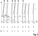
- the control circuit 40 is programmed in such a way that sequences of chronologically consecutive, non-overlapping, ie time-delayed ramps 48, 50, 52 are sent, such as 3 is shown. After each ramp, the switching network 36 is switched to a different switching state so that the next ramp is transmitted with a different selection of antenna elements. In 3 three different switching states TX are provided, between which there is a cyclic change. The ramps 48, 50, 52 thus differ in the selection of the antenna elements.
- Ramps that have the same reference number are sent with the same selection of antenna elements. Overall, a sequence of 64 ramps is run through in this way, for example, before a corresponding sequence begins with a different ramp gradient. In the example shown, all ramps 48, 50, 52 have the same center frequency, the same duration and the same frequency deviation and therefore also the same slope. However, this is not mandatory. Embodiments are also conceivable in which, for example, the center frequencies vary and in turn form a slowly rising or falling ramp.
- the successive ramps 48, 50, 52 of the sequence are counted with a running index j.
- the middle of each ramp is denoted by t TX,n , the first index "TX" indicating the switching state and the second index n indicating the cycle consisting of three ramps (one for each switching state) in which the relevant ramp lies.
- the measurements in the various switching states are thus interleaved in time and extend over a relatively long period of time N ⁇ T, while the effective time offset (difference in center times) between the individual states is only ⁇ t 2 or ⁇ t 3 .
- each individual ramp (with the index j) is first subjected to a one-dimensional Fourier transformation.
- the baseband signal (complex amplitude as a function of time) is sampled at several times evenly distributed over the duration of the ramp. The sampling times are counted with an index k.
- a Fast Fourier Transform (FFT) is then applied to the samples obtained throughout the ramp, yielding a one-dimensional spectrum for this ramp, i.e. a complex amplitude s j as a function of a frequency variable f k .
- FFT Fast Fourier Transform
- ⁇ 0 is a phase offset dependent only on the distance R and the ramp gradient
- f R is the phase offset dependent on the distance R and the ramp gradient Frequency component
- f v is the Doppler frequency
- ⁇ is the sampling period when sampling each ramp (with index k).
- the first two terms in the above formula yield a value that depends on the frequency variable fk.
- the second term does not contain quantities that would be dependent on the sampling index k, and therefore only provides a constant phase factor, i.e. a factor that is independent of f k but oscillates as a function of time with the Doppler frequency f v .
- the ramp index j is used here as a time variable.
- the relative speed and thus the Doppler frequency can be regarded as constant, so that all three signals in 4 have the same frequency and are only shifted by one index point on the time axis.
- FIG. 5 An example of a common window function 54, a so-called emperor window, is given in figure 5 shown.
- the curve in figure 5 gives - as a function of row index j - the weight w with which the values of the in 4 signals shown are to be multiplied for the relevant row index j.
- FIG. 6 shows the result if the same window 54 is used for all three signals, which is shown in figure 5 is shown. However, you can see 6 that the three signals are not only shifted relative to each other on the time axis, but also have different waveforms because, since they are each shifted by a different amount from the curve 54, they are affected in different ways by the window function. This type of windowing would therefore lead to additional phase shifts in the second step of the Fourier transformation, which would make a comparison of the phases impossible or at least more difficult. Windowing is therefore performed using window functions that leave the waveform of the windowed signals unaltered.
- FIG. 13 shows three window functions indicated by curves 58, 60 and 62.
- Curves 58, 60, 62 have the same shape as the Imperial window in figure 5 , but are shifted on the time axis by the same amounts (T/3) as the associated ramps and, accordingly, the signals in 4 .
- phase offset ⁇ TX, ⁇ Given above, then one obtains one finds a set of phase relationships which, despite the relative movement of the object, practically do not depend on the object distance or the relative speed, but only on the run length difference determined by the azimuth angle ⁇ and which therefore enable an exact angle estimation by comparison with the antenna diagram.
Landscapes
- Engineering & Computer Science (AREA)
- Radar, Positioning & Navigation (AREA)
- Remote Sensing (AREA)
- Physics & Mathematics (AREA)
- Computer Networks & Wireless Communication (AREA)
- General Physics & Mathematics (AREA)
- Electromagnetism (AREA)
- Radar Systems Or Details Thereof (AREA)
- Traffic Control Systems (AREA)
Claims (4)
- Procédé de localisation d'objets avec un radar MIMO-FMCW, dans lequel- un signal radar à modulation de fréquence en forme de rampe est émis dont le schéma de modulation présente une séquence de rampes successives (48, 50, 52) décalées dans le temps,- au rythme des rampes successives, périodiquement par cycles, une commutation est effectuée entre au moins trois états de commutation (TX) qui se distinguent par la sélection des éléments d'antenne (24, 26, 28, 30) utilisés pour l'émission et pour la réception,- des échos radar reçus sont abaissés avec le signal émis en une bande de base,- les signaux de bande de base obtenus pour les différents états de commutation (TX) sont transformés en spectres à l'aide desquels les distances (R) et les vitesses relatives (v) des cibles radar (12, 14) sont déterminées, et- pour la détermination d'angles de localisation (θ) des cibles radar, les phases des signaux de bande de base (b) obtenus pour différents états de commutation sont comparées les unes aux autres, et- les signaux de bande de base sont soumis séparément pour chaque état de commutation (TX) à une transformation de Fourier bidimensionnelle, la transformation ayant lieu rampe par rampe dans la première dimension, et la transformation ayant lieu dans la deuxième dimension par l'intermédiaire d'un indice de rampe j qui compte les rampes (48, 50, 52) à l'intérieur de la séquence en utilisant des fonctions de fenêtre (58, 60, 62) qui maintiennent les formes d'onde des signaux de bande de base mis à part un décalage le long de l'axe du temps, et- les spectres obtenus pour différents états de commutation sont soumis à une correction de phase dépendant de la fréquence qui compense le décalage dans le temps des rampes,- les fonctions de fenêtre utilisées pour les différents états de commutation (TX) ayant la même forme mais présentant le même décalage dans le temps les unes par rapport aux autres que les rampes (48, 50, 52) associées,- les rampes (48, 50, 52) successives de la séquence étant comptées à l'aide d'un indice de rampe j courant, de sorte que- l'indice de rampe j est utilisé comme une variable de temps, et- la première rampe (j=1) du cycle présente un décalage dans le temps t0 par rapport à un temps de référence fixe t=0, la deuxième rampe (j=2) du cycle présente un décalage dans le temps Δt2 par rapport à la première rampe du cycle, et la troisième rampe (j=3) du cycle présente un décalage dans le temps Δt3 par rapport à la première rampe du cycle,- les durées Δt2 et Δt3 étant des durées de longueur différente.
- Procédé selon la revendication 1, dans lequel une commutation sur un autre état de commutation (TX) est effectuée après chaque rampe (48, 50, 52).
- Procédé selon l'une quelconque des revendications précédentes, dans lequel le nombre des rampes par séquence est supérieur à 20, de préférence supérieur à 60.
- Capteur radar MIMO-FMCW, comprenant un dispositif de commande et d'analyse (22) dans lequel est mis en œuvre un procédé selon l'une quelconque des revendications 1 à 3.
Applications Claiming Priority (3)
| Application Number | Priority Date | Filing Date | Title |
|---|---|---|---|
| DE102014210993 | 2014-06-10 | ||
| DE102014213190.1A DE102014213190A1 (de) | 2014-06-10 | 2014-07-08 | Verfahren zur Objektortung mit einem FMCW-Radar |
| PCT/EP2015/059897 WO2015188987A1 (fr) | 2014-06-10 | 2015-05-06 | Procédé de localisation d'objets à l'aide d'un radar fmcw |
Publications (2)
| Publication Number | Publication Date |
|---|---|
| EP3155444A1 EP3155444A1 (fr) | 2017-04-19 |
| EP3155444B1 true EP3155444B1 (fr) | 2022-10-05 |
Family
ID=54706736
Family Applications (1)
| Application Number | Title | Priority Date | Filing Date |
|---|---|---|---|
| EP15722979.0A Active EP3155444B1 (fr) | 2014-06-10 | 2015-05-06 | Procédé de localisation d'un objet avec un radar fmcw |
Country Status (6)
| Country | Link |
|---|---|
| US (1) | US10436890B2 (fr) |
| EP (1) | EP3155444B1 (fr) |
| JP (1) | JP6368801B2 (fr) |
| CN (1) | CN106461759B (fr) |
| DE (1) | DE102014213190A1 (fr) |
| WO (1) | WO2015188987A1 (fr) |
Families Citing this family (24)
| Publication number | Priority date | Publication date | Assignee | Title |
|---|---|---|---|---|
| EP3907529A1 (fr) * | 2016-07-01 | 2021-11-10 | Veoneer Sweden AB | Radar de véhicule pour détection de l'environnement |
| DE102017207604B4 (de) | 2017-05-05 | 2019-11-28 | Conti Temic Microelectronic Gmbh | Radarsystem mit Überwachung der Frequenzmodulation einer Folge von gleichartigen Sendesignalen |
| DE102017207607B4 (de) * | 2017-05-05 | 2025-01-30 | Continental Autonomous Mobility Germany GmbH | Radarsystem mit Überwachung der Frequenzlage einer Folge von gleichartigen Sendesignalen |
| CN108107428B (zh) * | 2017-12-07 | 2021-09-10 | 中国科学院电子学研究所 | 用于mimo阵列的相移偏移成像方法及装置 |
| US10718860B2 (en) * | 2018-01-11 | 2020-07-21 | Infineon Technologies Ag | System and method to improve range accuracy in FMCW radar using FSK modulated chirps |
| DE102018202293A1 (de) | 2018-02-15 | 2019-08-22 | Robert Bosch Gmbh | Schätzung von Quergeschwindigkeiten oder kartesischen Geschwindigkeiten von Punktzielen mit einem Radarsensor |
| DE102018206701A1 (de) * | 2018-05-02 | 2019-11-07 | Robert Bosch Gmbh | Überwachen eines FMCW-Radarsensors |
| DE102018210070A1 (de) * | 2018-06-21 | 2019-12-24 | Robert Bosch Gmbh | Verfahren zur Kalibrierung eines MIMO-Radarsensors für Kraftfahrzeuge |
| CN108984942B (zh) * | 2018-08-01 | 2022-09-20 | 桂林电子科技大学 | 基于随机频偏的频控阵雷达通信一体化波形设计方法 |
| DE102018121987A1 (de) | 2018-09-10 | 2020-03-12 | Infineon Technologies Ag | Frequenzmoduliertes Dauerstrich-Radarsystem |
| US11402483B2 (en) * | 2019-01-07 | 2022-08-02 | Niiva OpCo, LLC | Systems and methods to detect motion on sloped surfaces |
| US11360210B2 (en) * | 2019-07-02 | 2022-06-14 | Intel Corporation | Multi-mode multi-input multi-output (MIMO) radar sensors |
| CN115079095A (zh) * | 2019-08-19 | 2022-09-20 | 华为技术有限公司 | 信号传输方法及装置、信号处理方法及装置以及雷达系统 |
| DE102019215107A1 (de) * | 2019-09-27 | 2021-04-01 | Robert Bosch Gmbh | Verfahren und Vorrichtung zum Aussenden elektromagnetischer Strahlung und Empfangen von den Objekten reflektierter Teilstrahlung |
| US11378681B2 (en) * | 2019-10-30 | 2022-07-05 | Nxp Usa, Inc. | Systems and methods for automotive synthetic aperture radar |
| KR102775306B1 (ko) * | 2019-11-21 | 2025-03-05 | 삼성전자주식회사 | 운동 정보 결정 방법 및 장치 |
| FR3114711B1 (fr) * | 2020-08-31 | 2024-01-12 | Stmicroelectronics Grand Ouest Sas | Signal modulé en fréquence |
| JP7502977B2 (ja) | 2020-11-27 | 2024-06-19 | パナソニックオートモーティブシステムズ株式会社 | レーダ装置、レーダ信号生成回路、レーダ送信方法およびレーダ受信方法 |
| CN112666543B (zh) * | 2020-12-01 | 2023-10-27 | 安徽隼波科技有限公司 | 一种稀疏阵列tdm-mimo雷达及其校正方法 |
| JP7516233B2 (ja) | 2020-12-10 | 2024-07-16 | パナソニックオートモーティブシステムズ株式会社 | レーダ装置、レーダ信号処理回路、及び、レーダ信号処理方法 |
| CN112285690B (zh) * | 2020-12-25 | 2021-03-16 | 四川写正智能科技有限公司 | 毫米雷达波测距传感装置 |
| DE102021201073A1 (de) | 2021-02-05 | 2022-08-11 | Robert Bosch Gesellschaft mit beschränkter Haftung | MIMO-Radarsensor |
| US12111393B2 (en) | 2021-09-21 | 2024-10-08 | Apple Inc. | Electronic devices with multi-antenna sensing |
| KR20230111882A (ko) | 2022-01-19 | 2023-07-26 | 삼성전자주식회사 | 레이더 신호 처리 장치 및 방법 |
Family Cites Families (15)
| Publication number | Priority date | Publication date | Assignee | Title |
|---|---|---|---|---|
| CA1275403C (fr) * | 1985-06-07 | 1990-10-23 | Albert Rossi | Huile lubrifiante a combinaison double d'additifs pour ameliorer l'indice de viscosite a temperature |
| JP2768439B2 (ja) * | 1994-11-08 | 1998-06-25 | 本田技研工業株式会社 | Fm−cw方式マルチビームレーダー装置 |
| JP3575694B2 (ja) * | 2002-04-24 | 2004-10-13 | 株式会社ホンダエレシス | 走査型fmcwレーダ |
| JP4987456B2 (ja) | 2006-12-25 | 2012-07-25 | 三菱電機株式会社 | レーダ装置 |
| DE102007018470A1 (de) * | 2007-04-19 | 2008-10-23 | Robert Bosch Gmbh | Fahrerassistenzsystem und Verfahren zur Objektplausibilisierung |
| US7639171B2 (en) * | 2007-09-27 | 2009-12-29 | Delphi Technologies, Inc. | Radar system and method of digital beamforming |
| EP2629113B1 (fr) * | 2009-04-06 | 2017-04-26 | Conti Temic microelectronic GmbH | Système radar doté d'agencements et procédé pour découpler des signaux d'émission et de réception ainsi que pour annuler des rayonnements parasites |
| CN102893173B (zh) * | 2010-03-05 | 2014-12-03 | 温莎大学 | 雷达系统及其制作方法 |
| JP2010156708A (ja) | 2010-03-08 | 2010-07-15 | Mitsubishi Electric Corp | 車載用ミリ波レーダ装置 |
| JP2012202955A (ja) | 2011-03-28 | 2012-10-22 | Fujitsu Ten Ltd | ホログラフィックレーダ |
| US9121943B2 (en) * | 2011-05-23 | 2015-09-01 | Sony Corporation | Beam forming device and method |
| EP2541679A1 (fr) | 2011-06-30 | 2013-01-02 | Sony Corporation | Dispositif de formation de faisceau à large bande, dispositif d'orientation de faisceau à large bande et procédés correspondants |
| JP2013026817A (ja) | 2011-07-21 | 2013-02-04 | Mitsubishi Electric Corp | フェーズドアレーアンテナ |
| US20130151201A1 (en) * | 2011-12-08 | 2013-06-13 | John W. McCorkle | Method and system for processing received data |
| DE102013209708A1 (de) * | 2013-05-24 | 2014-11-27 | Robert Bosch Gmbh | Verfahren zum Betreiben eines MIMO Radars |
-
2014
- 2014-07-08 DE DE102014213190.1A patent/DE102014213190A1/de not_active Withdrawn
-
2015
- 2015-05-06 US US15/317,887 patent/US10436890B2/en active Active
- 2015-05-06 WO PCT/EP2015/059897 patent/WO2015188987A1/fr not_active Ceased
- 2015-05-06 CN CN201580030916.4A patent/CN106461759B/zh active Active
- 2015-05-06 JP JP2016571193A patent/JP6368801B2/ja not_active Expired - Fee Related
- 2015-05-06 EP EP15722979.0A patent/EP3155444B1/fr active Active
Also Published As
| Publication number | Publication date |
|---|---|
| JP2017522549A (ja) | 2017-08-10 |
| JP6368801B2 (ja) | 2018-08-01 |
| WO2015188987A1 (fr) | 2015-12-17 |
| US10436890B2 (en) | 2019-10-08 |
| EP3155444A1 (fr) | 2017-04-19 |
| CN106461759A (zh) | 2017-02-22 |
| DE102014213190A1 (de) | 2015-12-17 |
| CN106461759B (zh) | 2020-03-20 |
| US20170115384A1 (en) | 2017-04-27 |
Similar Documents
| Publication | Publication Date | Title |
|---|---|---|
| EP3155444B1 (fr) | Procédé de localisation d'un objet avec un radar fmcw | |
| DE102018127947B3 (de) | Mimo fmcw radarsystem | |
| EP3161514B1 (fr) | Procédé de mesure d'un mimo radar | |
| EP3161510B1 (fr) | Procédé de mesure par radar | |
| EP3014297B1 (fr) | Détecteur à radar fmcw à résolution angulaire | |
| EP3161513B1 (fr) | Procédé de mésure de radar avec des zones de vision différentes | |
| EP2507649B1 (fr) | Procédé de détermination univoque d'une distance et/ou d'une vitesse relative d'un objet, système d'assistance au conducteur et véhicule à moteur | |
| EP3752858B1 (fr) | Capteur radar à large bande à résolution angulaire pour véhicules automobiles | |
| DE69825341T2 (de) | Verfahren und Vorrichtung für dauerstrichfrequenzmodulierte Radardetektion mit Mehrdeutigkeitsauflösung zwischen Entfernung und Geschwindigkeit | |
| EP2948789B1 (fr) | Radar fmcw à répartition en plages de distance | |
| EP3752852B1 (fr) | Estimation de vitesses cartésiennes d'objets radar étendus au moyen d'un capteur radar | |
| EP3555654A1 (fr) | Détecteur radar à entrées et sorties multiples (mimo) pour véhicules automobiles | |
| EP3596499B1 (fr) | Procédé destiné à déterminer une distance et une vitesse d'un objet | |
| EP3752851B1 (fr) | Estimation de vitesses transversales ou de vitesses cartésiennes de cibles ponctuelles au moyen d'un capteur radar | |
| DE102020210079B3 (de) | Radarverfahren sowie Radarsystem mit hoher Entfernungsauflösung bei geringem Signalprozessierungsaufwand | |
| DE102013212079A1 (de) | Winkelauflösender Radarsensor | |
| WO2014075838A1 (fr) | Radar fmcw à chirp rapide | |
| EP3752859B1 (fr) | Estimation angulaire et résolution d'ambiguïté de capteurs radar pour véhicules automobiles comprenant un grand réseau d'antennes | |
| DE102017200706A1 (de) | Mehrfach unterabgetastetes Chirp-Sequence-Radar | |
| DE102020202500A1 (de) | MIMO-Radarsystem | |
| DE102018010369A1 (de) | Mimo fmcw radarsystem | |
| EP1643265B1 (fr) | Système radar pour véhicules | |
| DE102024208229A1 (de) | Verfahren zur Zieldetektion in einem DDM-Radarsensor | |
| DE102024208156A1 (de) | Radarsystem | |
| EP4662507A1 (fr) | Procédé de détection d'objet et système de capteur radar fmcw à résolution angulaire |
Legal Events
| Date | Code | Title | Description |
|---|---|---|---|
| STAA | Information on the status of an ep patent application or granted ep patent |
Free format text: STATUS: THE INTERNATIONAL PUBLICATION HAS BEEN MADE |
|
| PUAI | Public reference made under article 153(3) epc to a published international application that has entered the european phase |
Free format text: ORIGINAL CODE: 0009012 |
|
| STAA | Information on the status of an ep patent application or granted ep patent |
Free format text: STATUS: REQUEST FOR EXAMINATION WAS MADE |
|
| 17P | Request for examination filed |
Effective date: 20170110 |
|
| AK | Designated contracting states |
Kind code of ref document: A1 Designated state(s): AL AT BE BG CH CY CZ DE DK EE ES FI FR GB GR HR HU IE IS IT LI LT LU LV MC MK MT NL NO PL PT RO RS SE SI SK SM TR |
|
| AX | Request for extension of the european patent |
Extension state: BA ME |
|
| DAV | Request for validation of the european patent (deleted) | ||
| DAX | Request for extension of the european patent (deleted) | ||
| RAP1 | Party data changed (applicant data changed or rights of an application transferred) |
Owner name: ROBERT BOSCH GMBH |
|
| STAA | Information on the status of an ep patent application or granted ep patent |
Free format text: STATUS: EXAMINATION IS IN PROGRESS |
|
| 17Q | First examination report despatched |
Effective date: 20200508 |
|
| RIC1 | Information provided on ipc code assigned before grant |
Ipc: G01S 13/02 20060101ALN20220503BHEP Ipc: G01S 13/536 20060101ALN20220503BHEP Ipc: G01S 13/931 20200101ALN20220503BHEP Ipc: G01S 7/35 20060101ALI20220503BHEP Ipc: G01S 13/58 20060101ALI20220503BHEP Ipc: G01S 13/42 20060101ALI20220503BHEP Ipc: G01S 13/34 20060101AFI20220503BHEP |
|
| REG | Reference to a national code |
Ref country code: DE Ref legal event code: R079 Ref document number: 502015016095 Country of ref document: DE Free format text: PREVIOUS MAIN CLASS: G01S0007350000 Ipc: G01S0013340000 |
|
| RIC1 | Information provided on ipc code assigned before grant |
Ipc: G01S 13/02 20060101ALN20220512BHEP Ipc: G01S 13/536 20060101ALN20220512BHEP Ipc: G01S 13/931 20200101ALN20220512BHEP Ipc: G01S 7/35 20060101ALI20220512BHEP Ipc: G01S 13/58 20060101ALI20220512BHEP Ipc: G01S 13/42 20060101ALI20220512BHEP Ipc: G01S 13/34 20060101AFI20220512BHEP |
|
| GRAP | Despatch of communication of intention to grant a patent |
Free format text: ORIGINAL CODE: EPIDOSNIGR1 |
|
| STAA | Information on the status of an ep patent application or granted ep patent |
Free format text: STATUS: GRANT OF PATENT IS INTENDED |
|
| RIC1 | Information provided on ipc code assigned before grant |
Ipc: G01S 13/02 20060101ALN20220610BHEP Ipc: G01S 13/536 20060101ALN20220610BHEP Ipc: G01S 13/931 20200101ALN20220610BHEP Ipc: G01S 7/35 20060101ALI20220610BHEP Ipc: G01S 13/58 20060101ALI20220610BHEP Ipc: G01S 13/42 20060101ALI20220610BHEP Ipc: G01S 13/34 20060101AFI20220610BHEP |
|
| INTG | Intention to grant announced |
Effective date: 20220714 |
|
| GRAS | Grant fee paid |
Free format text: ORIGINAL CODE: EPIDOSNIGR3 |
|
| GRAA | (expected) grant |
Free format text: ORIGINAL CODE: 0009210 |
|
| STAA | Information on the status of an ep patent application or granted ep patent |
Free format text: STATUS: THE PATENT HAS BEEN GRANTED |
|
| AK | Designated contracting states |
Kind code of ref document: B1 Designated state(s): AL AT BE BG CH CY CZ DE DK EE ES FI FR GB GR HR HU IE IS IT LI LT LU LV MC MK MT NL NO PL PT RO RS SE SI SK SM TR |
|
| REG | Reference to a national code |
Ref country code: GB Ref legal event code: FG4D Free format text: NOT ENGLISH |
|
| REG | Reference to a national code |
Ref country code: CH Ref legal event code: EP |
|
| REG | Reference to a national code |
Ref country code: AT Ref legal event code: REF Ref document number: 1523076 Country of ref document: AT Kind code of ref document: T Effective date: 20221015 |
|
| REG | Reference to a national code |
Ref country code: DE Ref legal event code: R096 Ref document number: 502015016095 Country of ref document: DE |
|
| REG | Reference to a national code |
Ref country code: IE Ref legal event code: FG4D Free format text: LANGUAGE OF EP DOCUMENT: GERMAN |
|
| REG | Reference to a national code |
Ref country code: SE Ref legal event code: TRGR |
|
| REG | Reference to a national code |
Ref country code: LT Ref legal event code: MG9D |
|
| REG | Reference to a national code |
Ref country code: NL Ref legal event code: MP Effective date: 20221005 |
|
| PG25 | Lapsed in a contracting state [announced via postgrant information from national office to epo] |
Ref country code: NL Free format text: LAPSE BECAUSE OF FAILURE TO SUBMIT A TRANSLATION OF THE DESCRIPTION OR TO PAY THE FEE WITHIN THE PRESCRIBED TIME-LIMIT Effective date: 20221005 |
|
| PG25 | Lapsed in a contracting state [announced via postgrant information from national office to epo] |
Ref country code: PT Free format text: LAPSE BECAUSE OF FAILURE TO SUBMIT A TRANSLATION OF THE DESCRIPTION OR TO PAY THE FEE WITHIN THE PRESCRIBED TIME-LIMIT Effective date: 20230206 Ref country code: NO Free format text: LAPSE BECAUSE OF FAILURE TO SUBMIT A TRANSLATION OF THE DESCRIPTION OR TO PAY THE FEE WITHIN THE PRESCRIBED TIME-LIMIT Effective date: 20230105 Ref country code: LT Free format text: LAPSE BECAUSE OF FAILURE TO SUBMIT A TRANSLATION OF THE DESCRIPTION OR TO PAY THE FEE WITHIN THE PRESCRIBED TIME-LIMIT Effective date: 20221005 Ref country code: FI Free format text: LAPSE BECAUSE OF FAILURE TO SUBMIT A TRANSLATION OF THE DESCRIPTION OR TO PAY THE FEE WITHIN THE PRESCRIBED TIME-LIMIT Effective date: 20221005 Ref country code: ES Free format text: LAPSE BECAUSE OF FAILURE TO SUBMIT A TRANSLATION OF THE DESCRIPTION OR TO PAY THE FEE WITHIN THE PRESCRIBED TIME-LIMIT Effective date: 20221005 |
|
| PG25 | Lapsed in a contracting state [announced via postgrant information from national office to epo] |
Ref country code: RS Free format text: LAPSE BECAUSE OF FAILURE TO SUBMIT A TRANSLATION OF THE DESCRIPTION OR TO PAY THE FEE WITHIN THE PRESCRIBED TIME-LIMIT Effective date: 20221005 Ref country code: PL Free format text: LAPSE BECAUSE OF FAILURE TO SUBMIT A TRANSLATION OF THE DESCRIPTION OR TO PAY THE FEE WITHIN THE PRESCRIBED TIME-LIMIT Effective date: 20221005 Ref country code: LV Free format text: LAPSE BECAUSE OF FAILURE TO SUBMIT A TRANSLATION OF THE DESCRIPTION OR TO PAY THE FEE WITHIN THE PRESCRIBED TIME-LIMIT Effective date: 20221005 Ref country code: IS Free format text: LAPSE BECAUSE OF FAILURE TO SUBMIT A TRANSLATION OF THE DESCRIPTION OR TO PAY THE FEE WITHIN THE PRESCRIBED TIME-LIMIT Effective date: 20230205 Ref country code: HR Free format text: LAPSE BECAUSE OF FAILURE TO SUBMIT A TRANSLATION OF THE DESCRIPTION OR TO PAY THE FEE WITHIN THE PRESCRIBED TIME-LIMIT Effective date: 20221005 Ref country code: GR Free format text: LAPSE BECAUSE OF FAILURE TO SUBMIT A TRANSLATION OF THE DESCRIPTION OR TO PAY THE FEE WITHIN THE PRESCRIBED TIME-LIMIT Effective date: 20230106 |
|
| REG | Reference to a national code |
Ref country code: DE Ref legal event code: R097 Ref document number: 502015016095 Country of ref document: DE |
|
| PG25 | Lapsed in a contracting state [announced via postgrant information from national office to epo] |
Ref country code: SM Free format text: LAPSE BECAUSE OF FAILURE TO SUBMIT A TRANSLATION OF THE DESCRIPTION OR TO PAY THE FEE WITHIN THE PRESCRIBED TIME-LIMIT Effective date: 20221005 Ref country code: RO Free format text: LAPSE BECAUSE OF FAILURE TO SUBMIT A TRANSLATION OF THE DESCRIPTION OR TO PAY THE FEE WITHIN THE PRESCRIBED TIME-LIMIT Effective date: 20221005 Ref country code: EE Free format text: LAPSE BECAUSE OF FAILURE TO SUBMIT A TRANSLATION OF THE DESCRIPTION OR TO PAY THE FEE WITHIN THE PRESCRIBED TIME-LIMIT Effective date: 20221005 Ref country code: DK Free format text: LAPSE BECAUSE OF FAILURE TO SUBMIT A TRANSLATION OF THE DESCRIPTION OR TO PAY THE FEE WITHIN THE PRESCRIBED TIME-LIMIT Effective date: 20221005 Ref country code: CZ Free format text: LAPSE BECAUSE OF FAILURE TO SUBMIT A TRANSLATION OF THE DESCRIPTION OR TO PAY THE FEE WITHIN THE PRESCRIBED TIME-LIMIT Effective date: 20221005 |
|
| PLBE | No opposition filed within time limit |
Free format text: ORIGINAL CODE: 0009261 |
|
| STAA | Information on the status of an ep patent application or granted ep patent |
Free format text: STATUS: NO OPPOSITION FILED WITHIN TIME LIMIT |
|
| PG25 | Lapsed in a contracting state [announced via postgrant information from national office to epo] |
Ref country code: SK Free format text: LAPSE BECAUSE OF FAILURE TO SUBMIT A TRANSLATION OF THE DESCRIPTION OR TO PAY THE FEE WITHIN THE PRESCRIBED TIME-LIMIT Effective date: 20221005 Ref country code: AL Free format text: LAPSE BECAUSE OF FAILURE TO SUBMIT A TRANSLATION OF THE DESCRIPTION OR TO PAY THE FEE WITHIN THE PRESCRIBED TIME-LIMIT Effective date: 20221005 |
|
| 26N | No opposition filed |
Effective date: 20230706 |
|
| PG25 | Lapsed in a contracting state [announced via postgrant information from national office to epo] |
Ref country code: SI Free format text: LAPSE BECAUSE OF FAILURE TO SUBMIT A TRANSLATION OF THE DESCRIPTION OR TO PAY THE FEE WITHIN THE PRESCRIBED TIME-LIMIT Effective date: 20221005 |
|
| REG | Reference to a national code |
Ref country code: CH Ref legal event code: PL |
|
| PG25 | Lapsed in a contracting state [announced via postgrant information from national office to epo] |
Ref country code: MC Free format text: LAPSE BECAUSE OF FAILURE TO SUBMIT A TRANSLATION OF THE DESCRIPTION OR TO PAY THE FEE WITHIN THE PRESCRIBED TIME-LIMIT Effective date: 20221005 |
|
| REG | Reference to a national code |
Ref country code: BE Ref legal event code: MM Effective date: 20230531 |
|
| PG25 | Lapsed in a contracting state [announced via postgrant information from national office to epo] |
Ref country code: MC Free format text: LAPSE BECAUSE OF FAILURE TO SUBMIT A TRANSLATION OF THE DESCRIPTION OR TO PAY THE FEE WITHIN THE PRESCRIBED TIME-LIMIT Effective date: 20221005 Ref country code: LU Free format text: LAPSE BECAUSE OF NON-PAYMENT OF DUE FEES Effective date: 20230506 Ref country code: LI Free format text: LAPSE BECAUSE OF NON-PAYMENT OF DUE FEES Effective date: 20230531 Ref country code: CH Free format text: LAPSE BECAUSE OF NON-PAYMENT OF DUE FEES Effective date: 20230531 |
|
| REG | Reference to a national code |
Ref country code: IE Ref legal event code: MM4A |
|
| PG25 | Lapsed in a contracting state [announced via postgrant information from national office to epo] |
Ref country code: IE Free format text: LAPSE BECAUSE OF NON-PAYMENT OF DUE FEES Effective date: 20230506 |
|
| PG25 | Lapsed in a contracting state [announced via postgrant information from national office to epo] |
Ref country code: IE Free format text: LAPSE BECAUSE OF NON-PAYMENT OF DUE FEES Effective date: 20230506 |
|
| PG25 | Lapsed in a contracting state [announced via postgrant information from national office to epo] |
Ref country code: IT Free format text: LAPSE BECAUSE OF FAILURE TO SUBMIT A TRANSLATION OF THE DESCRIPTION OR TO PAY THE FEE WITHIN THE PRESCRIBED TIME-LIMIT Effective date: 20221005 Ref country code: BE Free format text: LAPSE BECAUSE OF NON-PAYMENT OF DUE FEES Effective date: 20230531 |
|
| PGFP | Annual fee paid to national office [announced via postgrant information from national office to epo] |
Ref country code: GB Payment date: 20240522 Year of fee payment: 10 |
|
| REG | Reference to a national code |
Ref country code: AT Ref legal event code: MM01 Ref document number: 1523076 Country of ref document: AT Kind code of ref document: T Effective date: 20230506 |
|
| PG25 | Lapsed in a contracting state [announced via postgrant information from national office to epo] |
Ref country code: AT Free format text: LAPSE BECAUSE OF NON-PAYMENT OF DUE FEES Effective date: 20230506 |
|
| PG25 | Lapsed in a contracting state [announced via postgrant information from national office to epo] |
Ref country code: AT Free format text: LAPSE BECAUSE OF NON-PAYMENT OF DUE FEES Effective date: 20230506 |
|
| PGFP | Annual fee paid to national office [announced via postgrant information from national office to epo] |
Ref country code: FR Payment date: 20240516 Year of fee payment: 10 |
|
| PGFP | Annual fee paid to national office [announced via postgrant information from national office to epo] |
Ref country code: SE Payment date: 20240522 Year of fee payment: 10 |
|
| PG25 | Lapsed in a contracting state [announced via postgrant information from national office to epo] |
Ref country code: BG Free format text: LAPSE BECAUSE OF FAILURE TO SUBMIT A TRANSLATION OF THE DESCRIPTION OR TO PAY THE FEE WITHIN THE PRESCRIBED TIME-LIMIT Effective date: 20221005 |
|
| PG25 | Lapsed in a contracting state [announced via postgrant information from national office to epo] |
Ref country code: BG Free format text: LAPSE BECAUSE OF FAILURE TO SUBMIT A TRANSLATION OF THE DESCRIPTION OR TO PAY THE FEE WITHIN THE PRESCRIBED TIME-LIMIT Effective date: 20221005 |
|
| PG25 | Lapsed in a contracting state [announced via postgrant information from national office to epo] |
Ref country code: CY Free format text: LAPSE BECAUSE OF FAILURE TO SUBMIT A TRANSLATION OF THE DESCRIPTION OR TO PAY THE FEE WITHIN THE PRESCRIBED TIME-LIMIT; INVALID AB INITIO Effective date: 20150506 |
|
| PG25 | Lapsed in a contracting state [announced via postgrant information from national office to epo] |
Ref country code: HU Free format text: LAPSE BECAUSE OF FAILURE TO SUBMIT A TRANSLATION OF THE DESCRIPTION OR TO PAY THE FEE WITHIN THE PRESCRIBED TIME-LIMIT; INVALID AB INITIO Effective date: 20150506 |
|
| PGFP | Annual fee paid to national office [announced via postgrant information from national office to epo] |
Ref country code: DE Payment date: 20250716 Year of fee payment: 11 |
|
| PG25 | Lapsed in a contracting state [announced via postgrant information from national office to epo] |
Ref country code: TR Free format text: LAPSE BECAUSE OF FAILURE TO SUBMIT A TRANSLATION OF THE DESCRIPTION OR TO PAY THE FEE WITHIN THE PRESCRIBED TIME-LIMIT Effective date: 20221005 |
|
| PG25 | Lapsed in a contracting state [announced via postgrant information from national office to epo] |
Ref country code: SE Free format text: LAPSE BECAUSE OF NON-PAYMENT OF DUE FEES Effective date: 20250507 |
|
| REG | Reference to a national code |
Ref country code: SE Ref legal event code: EUG |
|
| GBPC | Gb: european patent ceased through non-payment of renewal fee |
Effective date: 20250506 |
|
| PG25 | Lapsed in a contracting state [announced via postgrant information from national office to epo] |
Ref country code: GB Free format text: LAPSE BECAUSE OF NON-PAYMENT OF DUE FEES Effective date: 20250506 |
|
| PG25 | Lapsed in a contracting state [announced via postgrant information from national office to epo] |
Ref country code: FR Free format text: LAPSE BECAUSE OF NON-PAYMENT OF DUE FEES Effective date: 20250531 |