EP3155444B1 - Verfahren zur objektortung mit einem fmcw-radar - Google Patents
Verfahren zur objektortung mit einem fmcw-radar Download PDFInfo
- Publication number
- EP3155444B1 EP3155444B1 EP15722979.0A EP15722979A EP3155444B1 EP 3155444 B1 EP3155444 B1 EP 3155444B1 EP 15722979 A EP15722979 A EP 15722979A EP 3155444 B1 EP3155444 B1 EP 3155444B1
- Authority
- EP
- European Patent Office
- Prior art keywords
- ramp
- time
- ramps
- radar
- frequency
- Prior art date
- Legal status (The legal status is an assumption and is not a legal conclusion. Google has not performed a legal analysis and makes no representation as to the accuracy of the status listed.)
- Active
Links
Images




Classifications
-
- G—PHYSICS
- G01—MEASURING; TESTING
- G01S—RADIO DIRECTION-FINDING; RADIO NAVIGATION; DETERMINING DISTANCE OR VELOCITY BY USE OF RADIO WAVES; LOCATING OR PRESENCE-DETECTING BY USE OF THE REFLECTION OR RERADIATION OF RADIO WAVES; ANALOGOUS ARRANGEMENTS USING OTHER WAVES
- G01S13/00—Systems using the reflection or reradiation of radio waves, e.g. radar systems; Analogous systems using reflection or reradiation of waves whose nature or wavelength is irrelevant or unspecified
- G01S13/02—Systems using reflection of radio waves, e.g. primary radar systems; Analogous systems
- G01S13/06—Systems determining position data of a target
- G01S13/42—Simultaneous measurement of distance and other co-ordinates
-
- G—PHYSICS
- G01—MEASURING; TESTING
- G01S—RADIO DIRECTION-FINDING; RADIO NAVIGATION; DETERMINING DISTANCE OR VELOCITY BY USE OF RADIO WAVES; LOCATING OR PRESENCE-DETECTING BY USE OF THE REFLECTION OR RERADIATION OF RADIO WAVES; ANALOGOUS ARRANGEMENTS USING OTHER WAVES
- G01S7/00—Details of systems according to groups G01S13/00, G01S15/00, G01S17/00
- G01S7/02—Details of systems according to groups G01S13/00, G01S15/00, G01S17/00 of systems according to group G01S13/00
- G01S7/35—Details of non-pulse systems
- G01S7/352—Receivers
- G01S7/354—Extracting wanted echo-signals
-
- G—PHYSICS
- G01—MEASURING; TESTING
- G01S—RADIO DIRECTION-FINDING; RADIO NAVIGATION; DETERMINING DISTANCE OR VELOCITY BY USE OF RADIO WAVES; LOCATING OR PRESENCE-DETECTING BY USE OF THE REFLECTION OR RERADIATION OF RADIO WAVES; ANALOGOUS ARRANGEMENTS USING OTHER WAVES
- G01S13/00—Systems using the reflection or reradiation of radio waves, e.g. radar systems; Analogous systems using reflection or reradiation of waves whose nature or wavelength is irrelevant or unspecified
- G01S13/02—Systems using reflection of radio waves, e.g. primary radar systems; Analogous systems
- G01S13/0209—Systems with very large relative bandwidth, i.e. larger than 10 %, e.g. baseband, pulse, carrier-free, ultrawideband
-
- G—PHYSICS
- G01—MEASURING; TESTING
- G01S—RADIO DIRECTION-FINDING; RADIO NAVIGATION; DETERMINING DISTANCE OR VELOCITY BY USE OF RADIO WAVES; LOCATING OR PRESENCE-DETECTING BY USE OF THE REFLECTION OR RERADIATION OF RADIO WAVES; ANALOGOUS ARRANGEMENTS USING OTHER WAVES
- G01S13/00—Systems using the reflection or reradiation of radio waves, e.g. radar systems; Analogous systems using reflection or reradiation of waves whose nature or wavelength is irrelevant or unspecified
- G01S13/02—Systems using reflection of radio waves, e.g. primary radar systems; Analogous systems
- G01S13/0218—Very long range radars, e.g. surface wave radar, over-the-horizon or ionospheric propagation systems
-
- G—PHYSICS
- G01—MEASURING; TESTING
- G01S—RADIO DIRECTION-FINDING; RADIO NAVIGATION; DETERMINING DISTANCE OR VELOCITY BY USE OF RADIO WAVES; LOCATING OR PRESENCE-DETECTING BY USE OF THE REFLECTION OR RERADIATION OF RADIO WAVES; ANALOGOUS ARRANGEMENTS USING OTHER WAVES
- G01S13/00—Systems using the reflection or reradiation of radio waves, e.g. radar systems; Analogous systems using reflection or reradiation of waves whose nature or wavelength is irrelevant or unspecified
- G01S13/02—Systems using reflection of radio waves, e.g. primary radar systems; Analogous systems
- G01S13/06—Systems determining position data of a target
- G01S13/08—Systems for measuring distance only
- G01S13/32—Systems for measuring distance only using transmission of continuous waves, whether amplitude-, frequency-, or phase-modulated, or unmodulated
- G01S13/34—Systems for measuring distance only using transmission of continuous waves, whether amplitude-, frequency-, or phase-modulated, or unmodulated using transmission of continuous, frequency-modulated waves while heterodyning the received signal, or a signal derived therefrom, with a locally-generated signal related to the contemporaneously transmitted signal
-
- G—PHYSICS
- G01—MEASURING; TESTING
- G01S—RADIO DIRECTION-FINDING; RADIO NAVIGATION; DETERMINING DISTANCE OR VELOCITY BY USE OF RADIO WAVES; LOCATING OR PRESENCE-DETECTING BY USE OF THE REFLECTION OR RERADIATION OF RADIO WAVES; ANALOGOUS ARRANGEMENTS USING OTHER WAVES
- G01S13/00—Systems using the reflection or reradiation of radio waves, e.g. radar systems; Analogous systems using reflection or reradiation of waves whose nature or wavelength is irrelevant or unspecified
- G01S13/02—Systems using reflection of radio waves, e.g. primary radar systems; Analogous systems
- G01S13/06—Systems determining position data of a target
- G01S13/08—Systems for measuring distance only
- G01S13/32—Systems for measuring distance only using transmission of continuous waves, whether amplitude-, frequency-, or phase-modulated, or unmodulated
- G01S13/34—Systems for measuring distance only using transmission of continuous waves, whether amplitude-, frequency-, or phase-modulated, or unmodulated using transmission of continuous, frequency-modulated waves while heterodyning the received signal, or a signal derived therefrom, with a locally-generated signal related to the contemporaneously transmitted signal
- G01S13/343—Systems for measuring distance only using transmission of continuous waves, whether amplitude-, frequency-, or phase-modulated, or unmodulated using transmission of continuous, frequency-modulated waves while heterodyning the received signal, or a signal derived therefrom, with a locally-generated signal related to the contemporaneously transmitted signal using sawtooth modulation
-
- G—PHYSICS
- G01—MEASURING; TESTING
- G01S—RADIO DIRECTION-FINDING; RADIO NAVIGATION; DETERMINING DISTANCE OR VELOCITY BY USE OF RADIO WAVES; LOCATING OR PRESENCE-DETECTING BY USE OF THE REFLECTION OR RERADIATION OF RADIO WAVES; ANALOGOUS ARRANGEMENTS USING OTHER WAVES
- G01S13/00—Systems using the reflection or reradiation of radio waves, e.g. radar systems; Analogous systems using reflection or reradiation of waves whose nature or wavelength is irrelevant or unspecified
- G01S13/02—Systems using reflection of radio waves, e.g. primary radar systems; Analogous systems
- G01S13/50—Systems of measurement based on relative movement of target
- G01S13/52—Discriminating between fixed and moving objects or between objects moving at different speeds
- G01S13/536—Discriminating between fixed and moving objects or between objects moving at different speeds using transmission of continuous unmodulated waves, amplitude-, frequency-, or phase-modulated waves
-
- G—PHYSICS
- G01—MEASURING; TESTING
- G01S—RADIO DIRECTION-FINDING; RADIO NAVIGATION; DETERMINING DISTANCE OR VELOCITY BY USE OF RADIO WAVES; LOCATING OR PRESENCE-DETECTING BY USE OF THE REFLECTION OR RERADIATION OF RADIO WAVES; ANALOGOUS ARRANGEMENTS USING OTHER WAVES
- G01S13/00—Systems using the reflection or reradiation of radio waves, e.g. radar systems; Analogous systems using reflection or reradiation of waves whose nature or wavelength is irrelevant or unspecified
- G01S13/02—Systems using reflection of radio waves, e.g. primary radar systems; Analogous systems
- G01S13/50—Systems of measurement based on relative movement of target
- G01S13/58—Velocity or trajectory determination systems; Sense-of-movement determination systems
- G01S13/583—Velocity or trajectory determination systems; Sense-of-movement determination systems using transmission of continuous unmodulated waves, amplitude-, frequency-, or phase-modulated waves and based upon the Doppler effect resulting from movement of targets
- G01S13/584—Velocity or trajectory determination systems; Sense-of-movement determination systems using transmission of continuous unmodulated waves, amplitude-, frequency-, or phase-modulated waves and based upon the Doppler effect resulting from movement of targets adapted for simultaneous range and velocity measurements
-
- G—PHYSICS
- G01—MEASURING; TESTING
- G01S—RADIO DIRECTION-FINDING; RADIO NAVIGATION; DETERMINING DISTANCE OR VELOCITY BY USE OF RADIO WAVES; LOCATING OR PRESENCE-DETECTING BY USE OF THE REFLECTION OR RERADIATION OF RADIO WAVES; ANALOGOUS ARRANGEMENTS USING OTHER WAVES
- G01S13/00—Systems using the reflection or reradiation of radio waves, e.g. radar systems; Analogous systems using reflection or reradiation of waves whose nature or wavelength is irrelevant or unspecified
- G01S13/88—Radar or analogous systems specially adapted for specific applications
- G01S13/93—Radar or analogous systems specially adapted for specific applications for anti-collision purposes
- G01S13/931—Radar or analogous systems specially adapted for specific applications for anti-collision purposes of land vehicles
-
- G—PHYSICS
- G01—MEASURING; TESTING
- G01S—RADIO DIRECTION-FINDING; RADIO NAVIGATION; DETERMINING DISTANCE OR VELOCITY BY USE OF RADIO WAVES; LOCATING OR PRESENCE-DETECTING BY USE OF THE REFLECTION OR RERADIATION OF RADIO WAVES; ANALOGOUS ARRANGEMENTS USING OTHER WAVES
- G01S7/00—Details of systems according to groups G01S13/00, G01S15/00, G01S17/00
- G01S7/02—Details of systems according to groups G01S13/00, G01S15/00, G01S17/00 of systems according to group G01S13/00
- G01S7/35—Details of non-pulse systems
- G01S7/352—Receivers
-
- G—PHYSICS
- G01—MEASURING; TESTING
- G01S—RADIO DIRECTION-FINDING; RADIO NAVIGATION; DETERMINING DISTANCE OR VELOCITY BY USE OF RADIO WAVES; LOCATING OR PRESENCE-DETECTING BY USE OF THE REFLECTION OR RERADIATION OF RADIO WAVES; ANALOGOUS ARRANGEMENTS USING OTHER WAVES
- G01S13/00—Systems using the reflection or reradiation of radio waves, e.g. radar systems; Analogous systems using reflection or reradiation of waves whose nature or wavelength is irrelevant or unspecified
- G01S13/02—Systems using reflection of radio waves, e.g. primary radar systems; Analogous systems
- G01S2013/0236—Special technical features
- G01S2013/0245—Radar with phased array antenna
-
- G—PHYSICS
- G01—MEASURING; TESTING
- G01S—RADIO DIRECTION-FINDING; RADIO NAVIGATION; DETERMINING DISTANCE OR VELOCITY BY USE OF RADIO WAVES; LOCATING OR PRESENCE-DETECTING BY USE OF THE REFLECTION OR RERADIATION OF RADIO WAVES; ANALOGOUS ARRANGEMENTS USING OTHER WAVES
- G01S7/00—Details of systems according to groups G01S13/00, G01S15/00, G01S17/00
- G01S7/02—Details of systems according to groups G01S13/00, G01S15/00, G01S17/00 of systems according to group G01S13/00
- G01S7/35—Details of non-pulse systems
- G01S7/352—Receivers
- G01S7/356—Receivers involving particularities of FFT processing
Definitions
- FMCW radar sensors are used to record the traffic environment, in particular to locate other vehicles.
- the location results can be used for various assistance functions, such as automatic distance control, an automatic collision warning or the automatic triggering of an emergency braking process if there is an acute risk of a collision.
- the frequency of the baseband signal corresponds to the difference in frequency between the signal being transmitted at a given time and the signal being received at the same time. Due to the frequency modulation of the transmission signal, this frequency difference depends on the propagation time of the signal from the radar sensor to the object and back, and thus on the distance of the object. Due to the Doppler effect, however, the frequency difference also contains a component that is caused by the relative speed of the object. The measurement of the frequency difference on a single ramp therefore does not yet allow the determination of the distance and the relative speed, but only provides a linear relationship between these quantities. This relationship can be represented as a straight line in a distance/velocity diagram (R-v diagram).
- a common type of FMCW radar uses alternating rising and falling frequency ramps. A different straight line is then obtained in the R-v diagram for each ramp, and the distance and the relative speed of the object are given by the intersection of these two straight lines.
- a sequence of identical, relatively short frequency ramps so-called “rapid chirps”
- This correction is determined by following the ramp-to-ramp phase change of the baseband signal. This exploits the fact that the phase of the baseband signal reacts relatively sensitively to the slight change in the object distance, which results from the relative movement of the object during the short time interval from one frequency ramp to the next.
- the relative speed can only be determined unambiguously if it is so small that the phase change is less than half a period (i.e. less than ⁇ ).
- the radar sensor usually has several antenna elements that are spaced apart on a line, for example a horizontal line, so that different azimuth angles of the located objects lead to differences in the path lengths that the radar signals have to travel from the object to the respective antenna element. These run length differences lead to corresponding differences in the phase of the signals that are received by the antenna elements and evaluated in the associated evaluation channels. By comparing the (complex) amplitudes received in the various channels with the corresponding amplitudes in an antenna diagram, the angle of incidence of the radar signal and thus the azimuth angle of the located object can then be determined.
- a greater angular resolution is achieved by not only working with a number of receiving antenna elements, but also with a number of transmitting antenna elements, with different combinations of transmitting and receiving antenna elements being evaluated.
- the varying positions of the transmitting antenna elements then lead to additional phase differences and thus to signals that are equivalent to signals that would be obtained with a configuration with a single transmitting antenna element and additional (virtual) receiving antenna elements. In this way, the aperture is virtually enlarged and thus the angular resolution is improved.
- the different transmission signals must be orthogonal to one another. This can be achieved, for example, by code division multiplex, frequency division multiplex or time division multiplex.
- the code multiplex method requires a great deal of effort and only allows a limited orthogonality of the signals.
- the disadvantage of frequency division multiplexing is that the phase and the Doppler shift depend on the respective wavelength.
- the method proposed here is therefore based on the time-division multiplex principle.
- Relative movements of the located objects in connection with the time offset between the different switching states lead to phase differences that make the subsequent angle estimation more difficult.
- One possibility of compensating for these phase shifts consists in estimating the phase shifts caused by the object movements on the basis of the measured relative speeds, which, however, is only possible with limited accuracy.
- the closest prior art is from EP 2 045 877 A1 a radar system and a method are known, in which the radar system comprises a first transmitting section of antenna elements, a second transmitting section of antenna elements and a receiving section of antenna elements, so that the receiving antenna elements form a multiplicity of subgroups representing real and synthetic antenna elements.
- the radar system also includes a transmitting/receiving device with a switching matrix. At least first and second switching transmitting antenna elements are configured and time-division multiplexed, increasing a receiving aperture of the receiving antenna elements.
- a first transmit signal is received by the real antenna elements and a second transmit signal is received by the real antenna elements and combined such that the signals received by the first switching transmit antenna element represent a signal received from the real receive antenna element and the signal received from the second switching transmit antenna element represents a signal received by the synthetic receiving antenna element.
- WO 2010/115418 A2 JP 2003 315447 A
- US 1008/150795 A1 and U.S. 5,652,589 A as state of the art.
- the object of the invention is to specify a time-division multiplex method for a MIMO radar that allows more accurate angle estimation.
- the invention allows the baseband signals, which are obtained one after the other for any number of switching states, to be related to a common reference point in time, so that the phase shifts caused by the object movements are eliminated without requiring an exact estimated value for the relative speeds of the objects .
- an FMCW radar sensor 10 is shown as a simplified block diagram, which is installed, for example, in the front of a motor vehicle and is used to measure distances R and relative speeds v from objects 12, 14, for example vehicles driving ahead.
- the radar sensor 10 has a voltage-controlled oscillator 16, which supplies a frequency-modulated transmission signal via a mixer 18 to a transmission and reception device 20, from which the signal is transmitted in the direction of the objects 12, 14.
- the signal reflected from the objects is received by the transmitting and receiving device 20 and mixed in the mixer 18 with a portion of the transmitted signal. In this way, a baseband signal b is obtained, which is further evaluated in an electronic evaluation and control device 22 .
- the transmitting and receiving device 20 has four antenna elements 24, 26, 28, 30, which together form a planar array antenna.
- the radar sensor is installed in the motor vehicle in such a way that the antenna elements 24-30 are next to one another at the same height, so that a certain angular resolution of the radar sensor in the horizontal (in the azimuth) is achieved.
- In 2 symbolically depicts radar beams received by the antenna elements at an azimuth angle ⁇ .
- a high-frequency part 34 for driving the antenna elements is formed, for example, by one or more MMICs (Monolithic Microwave Integrated Circuits) and includes a switching network 36 via which the individual antenna elements can be selectively connected to the oscillator 16 .
- the radar echoes received by the antenna elements 24 - 30 are each decoupled with the aid of a circulator 38 and fed to the mixer 18 where they are mixed with the transmission signal supplied by the oscillator 16 . In this way, a baseband signal b1, b2, b3, b4 is obtained for each of the antenna elements, which is supplied to the electronic control and evaluation device 22.
- the control and evaluation device 22 contains a control part 40 which controls the function of the oscillator 16 and the switching network 36 .
- the frequency of the transmission signal supplied by the oscillator 16 is periodically modulated in the form of a sequence of rising and/or falling frequency ramps.
- the different positions of the antenna elements 24 - 30 mean that the radar beams, which were emitted by one and the same antenna element, were reflected on the object and are then received by the different antenna elements, cover different run lengths and therefore phase differences which depend on the azimuth angle ⁇ of the object.
- the associated intermediate frequency signals b1-b4 also have corresponding phase differences.
- the amplitudes (magnitudes) of the received signals also differ from antenna element to antenna element, also depending on the azimuth angle ⁇ .
- the dependency of the complex amplitudes, ie the absolute values and phases, of the received signals on the azimuth angle ⁇ can be stored in the control and evaluation device 22 for each antenna element in the form of an antenna diagram.
- an angle estimator 46 compares the complex amplitudes obtained in the four reception channels with the antenna pattern, so as to estimate the azimuth angle ⁇ of the object.
- the most probable value for the azimuth angle is the value is assumed at which the measured amplitudes correlate best with the values read off the antenna diagrams.
- the complex amplitudes in the four channels are also dependent on which of the four antenna elements 24, 26, 28, 30 is used as the transmission element.
- the switching network 36 makes it possible to transmit a first frequency ramp with the antenna element 24 (the transmission array then consists only of the single antenna element 24), then to switch to the antenna element 26 and then successively to the antenna elements 28 and 30, after which a new cycle begins .
- This steering vector determines the phase relationships between the complex amplitudes of the signals received by the four antenna elements.
- the index ⁇ designates the antenna element, and the variables d r ⁇ indicate the positions of the antenna elements in the horizontal, based on any chosen origin.
- the product vector has sixteen components corresponding to sixteen positions of virtual antenna elements.
- the virtual antenna positions thus correspond to the sums that can be formed from the variables d1 - d4.
- the virtual array thus extends horizontally over a much larger span, which means it has a larger aperture and thus leads to a higher angular resolution, since even small changes in the azimuth angle ⁇ lead to larger phase differences.
- differently designed antenna arrays can also be used, for example those in which the antenna elements have different distances to each other.
- bistatic antenna concepts are possible, in which some antenna elements are used only for transmission and others only for reception.
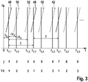
- the control circuit 40 is programmed in such a way that sequences of chronologically consecutive, non-overlapping, ie time-delayed ramps 48, 50, 52 are sent, such as 3 is shown. After each ramp, the switching network 36 is switched to a different switching state so that the next ramp is transmitted with a different selection of antenna elements. In 3 three different switching states TX are provided, between which there is a cyclic change. The ramps 48, 50, 52 thus differ in the selection of the antenna elements.
- Ramps that have the same reference number are sent with the same selection of antenna elements. Overall, a sequence of 64 ramps is run through in this way, for example, before a corresponding sequence begins with a different ramp gradient. In the example shown, all ramps 48, 50, 52 have the same center frequency, the same duration and the same frequency deviation and therefore also the same slope. However, this is not mandatory. Embodiments are also conceivable in which, for example, the center frequencies vary and in turn form a slowly rising or falling ramp.
- the successive ramps 48, 50, 52 of the sequence are counted with a running index j.
- the middle of each ramp is denoted by t TX,n , the first index "TX" indicating the switching state and the second index n indicating the cycle consisting of three ramps (one for each switching state) in which the relevant ramp lies.
- the measurements in the various switching states are thus interleaved in time and extend over a relatively long period of time N ⁇ T, while the effective time offset (difference in center times) between the individual states is only ⁇ t 2 or ⁇ t 3 .
- each individual ramp (with the index j) is first subjected to a one-dimensional Fourier transformation.
- the baseband signal (complex amplitude as a function of time) is sampled at several times evenly distributed over the duration of the ramp. The sampling times are counted with an index k.
- a Fast Fourier Transform (FFT) is then applied to the samples obtained throughout the ramp, yielding a one-dimensional spectrum for this ramp, i.e. a complex amplitude s j as a function of a frequency variable f k .
- FFT Fast Fourier Transform
- ⁇ 0 is a phase offset dependent only on the distance R and the ramp gradient
- f R is the phase offset dependent on the distance R and the ramp gradient Frequency component
- f v is the Doppler frequency
- ⁇ is the sampling period when sampling each ramp (with index k).
- the first two terms in the above formula yield a value that depends on the frequency variable fk.
- the second term does not contain quantities that would be dependent on the sampling index k, and therefore only provides a constant phase factor, i.e. a factor that is independent of f k but oscillates as a function of time with the Doppler frequency f v .
- the ramp index j is used here as a time variable.
- the relative speed and thus the Doppler frequency can be regarded as constant, so that all three signals in 4 have the same frequency and are only shifted by one index point on the time axis.
- FIG. 5 An example of a common window function 54, a so-called emperor window, is given in figure 5 shown.
- the curve in figure 5 gives - as a function of row index j - the weight w with which the values of the in 4 signals shown are to be multiplied for the relevant row index j.
- FIG. 6 shows the result if the same window 54 is used for all three signals, which is shown in figure 5 is shown. However, you can see 6 that the three signals are not only shifted relative to each other on the time axis, but also have different waveforms because, since they are each shifted by a different amount from the curve 54, they are affected in different ways by the window function. This type of windowing would therefore lead to additional phase shifts in the second step of the Fourier transformation, which would make a comparison of the phases impossible or at least more difficult. Windowing is therefore performed using window functions that leave the waveform of the windowed signals unaltered.
- FIG. 13 shows three window functions indicated by curves 58, 60 and 62.
- Curves 58, 60, 62 have the same shape as the Imperial window in figure 5 , but are shifted on the time axis by the same amounts (T/3) as the associated ramps and, accordingly, the signals in 4 .
- phase offset ⁇ TX, ⁇ Given above, then one obtains one finds a set of phase relationships which, despite the relative movement of the object, practically do not depend on the object distance or the relative speed, but only on the run length difference determined by the azimuth angle ⁇ and which therefore enable an exact angle estimation by comparison with the antenna diagram.
Landscapes
- Engineering & Computer Science (AREA)
- Radar, Positioning & Navigation (AREA)
- Remote Sensing (AREA)
- Physics & Mathematics (AREA)
- Computer Networks & Wireless Communication (AREA)
- General Physics & Mathematics (AREA)
- Electromagnetism (AREA)
- Radar Systems Or Details Thereof (AREA)
- Traffic Control Systems (AREA)
Description
- Die Erfindung betrifft ein Verfahren zur Ortung von Objekten mit einem MIMO-FMCW-Radar, bei dem:
- ein rampenförmig frequenzmoduliertes Radarsignal gesendet wird, dessen Modulationsmuster eine Sequenz zeitversetzt aufeinander folgender Rampen aufweist,
- im Takt der aufeinander folgenden Rampen periodisch zwischen mindestens zwei Schaltzuständen umgeschaltet wird, die sich in der Auswahl der zum Senden und zum Empfang verwendeten Antennenelemente unterscheiden,
- empfangene Radarechos mit dem gesendeten Signal in ein Basisband herunter gemischt werden,
- die für die verschiedenen Schaltzustände erhaltenen Basisbandsignale in Spektren transformiert werden, anhand derer die Abstände und Relativgeschwindigkeiten der Radarziele bestimmt werden, und
- zur Bestimmung von Ortungswinkeln der Radarziele die Phasen der für verschiedene Schaltzustände erhaltenen Basisbandsignale miteinander verglichen werden.
- Weiterhin betrifft die Erfindung einen Radarsensor, insbesondere für Kraftfahrzeuge, der zur Durchführung dieses Verfahrens ausgebildet ist.
- Bei Kraftfahrzeugen werden FMCW-Radarsensoren zur Erfassung des Verkehrsumfelds eingesetzt, insbesondere zur Ortung anderer Fahrzeuge. Die Ortungsergebnisse können für verschiedene Assistenzfunktionen genutzt werden, beispielsweise für eine automatische Abstandsregelung, eine automatische Kollisionswarnung oder auch die automatische Auslösung eines Notbremsvorgangs bei akuter Kollisionsgefahr.
- Die Frequenz des Basisbandsignals entspricht dem Frequenzunterschied zwischen dem zu einem gegebenen Zeitpunkt gesendeten Signal und dem zum selben Zeitpunkt empfangenen Signal. Aufgrund der Frequenzmodulation des Sendesignals ist dieser Frequenzunterschied von der Laufzeit des Signals vom Radarsensor zum Objekt und zurück und somit vom Abstand des Objekts abhängig. Aufgrund des Doppler-Effektes enthält der Frequenzunterschied jedoch auch einen Anteil, der durch die Relativgeschwindigkeit des Objekts bedingt ist. Die Messung des Frequenzunterschieds auf einer einzelnen Rampe erlaubt deshalb noch keine Bestimmung des Abstands und der Relativgeschwindigkeit, sondern liefert nur eine lineare Beziehung zwischen diesen Größen. Diese Beziehung lässt sich in einem Abstands/Geschwindigkeits-Diagramm (R-v-Diagramm) als Gerade darstellen.
- Um eindeutige Werte für den Abstand und die Relativgeschwindigkeit zu erhalten, wird bei einem gebräuchlichen Typ eines FMCW-Radars mit einander abwechselnden steigenden und fallenden Frequenzrampen gearbeitet. Im R-v-Diagramm erhält man dann für jede Rampe eine andere Gerade, und der Abstand und die Relativgeschwindigkeit des Objekts sind durch den Schnittpunkt dieser beiden Geraden gegeben.
- In einer anderen Ausführungsform wird mit einer Folge von identischen, verhältnismäßig kurzen Frequenzrampen, sogenannten "Rapid Chirps" gearbeitet, die im Verhältnis zu ihrer Dauer einen hohen Frequenzhub haben und deshalb so steil sind, dass im Basisbandsignal der abstandsabhängige Anteil dominiert, während der Doppleranteil nur eine kleine Korrektur darstellt. Diese Korrektur wird dadurch bestimmt, dass man die Phasenänderung des Basisbandsignals von Rampe zu Rampe verfolgt. Dabei wird der Umstand ausgenutzt, dass die Phase des Basisbandsignals relativ empfindlich auf die geringe Änderung des Objektsabstands reagiert, die aus der Relativbewegung des Objektes während des kurzen Zeitintervalls von einer Frequenzrampe zur nächsten resultiert.
- Da die Phasenänderung jedoch eine periodische Funktion der Relativgeschwindigkeit ist, lässt sich die Relativgeschwindigkeit nur dann eindeutig bestimmen, wenn sie so klein ist, dass die Phasenänderung weniger als eine halbe Periode (also weniger als π) beträgt.
- Zumeist weist der Radarsensor mehrere Antennenelemente auf, die in Abstand zueinander auf einer Linie, beispielsweise einer Horizontalen angeordnet sind, so dass unterschiedliche Azimutwinkel der georteten Objekte zu Differenzen in den Lauflängen führen, die die Radarsignale vom Objekt bis zum jeweiligen Antennenelement zurückzulegen haben. Diese Lauflängendifferenzen führen zu entsprechenden Unterschieden in der Phase der Signale, die von den Antennenelementen empfangen und in den zugehörigen Auswertungskanälen ausgewertet werden. Durch Abgleich der in den verschiedenen Kanälen empfangenen (komplexen) Amplituden mit entsprechenden Amplituden in einem Antennendiagramm lässt sich dann der Einfallswinkel des Radarsignals und damit der Azimutwinkel des georteten Objekts bestimmen.
- Bei einem MIMO-Radar (Multiple Input / Multiple Output) wird ein größeres Winkelauflösungsvermögen dadurch erreicht, dass man nicht nur mit mehreren empfangenden Antennenelementen arbeitet, sondern auch mit mehreren sendenden Antennenelementen, wobei unterschiedliche Kombinationen von sendenden und empfangenden Antennenelementen ausgewertet werden. Die variierenden Positionen der sendenden Antennenelemente führen dann zu zusätzlichen Phasendifferenzen und damit zu Signalen, die äquivalent sind zu Signalen, die man mit einer Konfiguration mit einem einzelnen sendenden Antennenelement und zusätzlichen (virtuellen) empfangenden Antennenelementen erhalten würde. Auf diese Weise wird die Apertur virtuell vergrößert und damit die Winkelauflösung verbessert.
- Bei einem MIMO-Radar müssen die verschiedenen Sendesignale zueinander orthogonal sein. Das lässt sich beispielsweise durch Codemultiplex, Frequenzmultiplex oder Zeitmultiplex erreichen. Das Codemultiplex-Verfahren erfordert jedoch einen hohen Aufwand und ermöglicht nur eine begrenzte Orthogonalität der Signale. Bei Frequenzmultiplex-Verfahren besteht der Nachteil, dass die Phase und die Doppler-Verschiebung von der jeweiligen Wellenlänge abhängig sind. Das hier vorgeschlagene Verfahren basiert deshalb auf dem Zeitmultiplex-Prinzip. Allerdings besteht dabei das Problem, dass Relativbewegungen der georteten Objekte in Verbindung mit dem Zeitversatz zwischen den verschiedenen Schaltzuständen zu Phasenunterschieden führen, die die nachfolgende Winkelschätzung erschweren. Eine Möglichkeit, diese Phasenverschiebungen zu kompensieren, besteht darin, dass anhand der gemessenen Relativgeschwindigkeiten die durch die Objektbewegungen verursachen Phasenverschiebungen geschätzt werden, was jedoch nur mit begrenzter Genauigkeit möglich ist.
- Als nächstkommender Stand der Technik ist aus der
EP 2 045 877 A1 ein Radarsystem und ein Verfahren bekannt, bei dem das Radarsystem einen ersten Sendeabschnitt von Antennenelementen, einen zweiten Sendeabschnitt von Antennenelementen und einen Empfangsabschnitt von Antennenelementen umfasst, so dass die empfangenden Antennenelemente eine Vielzahl von Untergruppen bilden, die reale und synthetische Antennenelemente darstellen. Das Radarsystem umfasst ferner eine Sende-/Empfangsvorrichtung mit einer Schaltmatrix. Mindestens ein erstes und ein zweites schaltendes Sendeantennenelement sind konfiguriert und zeitmultiplexiert, wobei eine Empfangsapertur der Empfangsantennenelemente vergrößert wird. Ein erstes Sendesignal wird von den realen Antennenelementen empfangen und ein zweites Sendesignal wird von den realen Antennenelementen empfangen und so kombiniert, dass die von dem ersten schaltenden Sendeantennenelement empfangenen Signale ein von dem realen Empfangsantennenelement empfangenes Signal darstellen, und das von dem zweiten schaltenden Sendeantennenelement empfangene Signal ein von dem synthetischen Empfangsantennenelement empfangenes Signal darstellt. Darüber ist aufWO 2010/115418 A2 ,JP 2003 315447 A US 1008/150795 A1 undUS 5 652 589 A als Stand der Technik zu verweisen. - Aufgabe der Erfindung ist es, ein Zeitmultiplex-Verfahren für ein MIMO-Radar anzugeben, das es eine genauere Winkelschätzung erlaubt.
- Diese Aufgabe wird erfindungsgemäß durch die Kombination der Merkmale des unabhängigen Anspruchs gelöst.
- Die Erfindung erlaubt es, die Basisbandsignale, die nacheinander für eine beliebige Anzahl von Schaltzuständen erhalten werden, auf einen gemeinsamen Referenzzeitpunkt zu beziehen, so dass die durch die Objektbewegungen verursachten Phasenverschiebungen eliminiert werden, ohne dass dazu ein genauer Schätzwert für die Relativgeschwindigkeiten der Objekte benötigt wird.
- Vorteilhafte Ausgestaltungen der Erfindung sind in den Unteransprüchen angegeben.
- Im folgenden wird ein Ausführungsbeispiel anhand der Zeichnung näher erläutert.
- Es zeigen:
- Fig. 1
- ein Blockdiagramm eines FMCW-Radarsystems;
- Fig. 2
- ein detaillierteres Blockdiagramm eines MIMO-Radarsensors;
- Fig. 3
- ein Modulationsmuster mit wiederholten Abfolgen von drei zeitversetzten Rampen, die mit unterschiedlichen Antennenkonfigurationen gesendet und empfangen werden;
- Fig. 4
- ungefensterte Basisbandsignale zu den drei Rampen nach
Fig. 3 , dargestellt in Form der Amplitudenbeträge als Funktionen eines Rampenindex j; - Fig. 5
- eine einzelne Fensterfunktion;
- Fig. 6
- die Basisbandsignale gemäß
Fig. 4 nach Fensterung mit der Fensterfunktion nachFig. 5 ; - Fig. 7
- drei zeitversetzte Fensterfunktionen; und
- Fig. 8
- die Basisbandsignale gemäß
Fig. 4 nach Fensterung mit den Fensterfunktionen nachFig. 7 . - In
Fig. 1 ist als vereinfachtes Blockdiagramm ein FMCW-Radarsensor 10 dargestellt, der beispielsweise vorn in einem Kraftfahrzeug eingebaut ist und dazu dient, Abstände R und Relativgeschwindigkeiten v von Objekten 12, 14 zu messen, beispielsweise von vorausfahrenden Fahrzeugen. Der Radarsensor 10 weist einen spannungsgesteuerten Oszillator 16 auf, der ein frequenzmoduliertes Sendesignal über einen Mischer 18 an eine Sende- und Empfangseinrichtung 20 liefert, von der das Signal in Richtung auf die Objekte 12, 14 ausgesandt wird. - Das an den Objekten reflektierte Signal wird von der Sende- und Empfangseinrichtung 20 empfangen und im Mischer 18 mit einem Anteil des Sendesignals gemischt. Auf diese Weise erhält man ein Basisbandsignal b, das in einer elektronischen Auswerte- und Steuereinrichtung 22 weiter ausgewertet wird.
- Wie in
Fig. 2 gezeigt ist, weist die Sende- und Empfangseinrichtung 20 vier Antennenelemente 24, 26, 28, 30 auf, die zusammen eine planare Gruppenantenne bilden. Der Radarsensor wird so in das Kraftfahrzeug eingebaut, dass die Antennenelemente 24 - 30 auf gleicher Höhe nebeneinander liegen, so dass ein gewisses Winkelauflösungsvermögen des Radarsensors in der Horizontalen (im Azimut) erreicht wird. InFig. 2 sind symbolisch Radarstrahlen dargestellt, die von den Antennenelementen unter einem Azimutwinkel θ empfangen werden. - Ein Hochfrequenzteil 34 zur Ansteuerung der Antennenelemente wird beispielsweise durch ein oder mehrere MMICs (Monolithic Microwave Integrated Circuits) gebildet und umfasst ein Schaltnetzwerk 36, über das die einzelnen Antennenelemente selektiv mit dem Oszillator 16 verbindbar sind. Die von den Antennenelementen 24 - 30 empfangenen Radarechos werden jeweils mit Hilfe eines Zirkulators 38 ausgekoppelt und dem Mischer 18 zugeführt, wo sie mit dem vom Oszillator 16 gelieferten Sendesignal gemischt werden. Auf diese Weise erhält man für jedes der Antennenelemente ein Basisbandsignal b1, b2, b3, b4, das der elektronischen Steuer- und Auswerteeinrichtung 22 zugeführt wird.
- Die Steuer- und Auswerteeinrichtung 22 enthält einen Steuerungsteil 40, der die Funktion des Oszillators 16 und des Schaltnetzwerkes 36 steuert. Die Frequenz des vom Oszillator 16 gelieferten Sendesignals wird periodisch in Form einer Folge von steigenden und/oder fallenden Frequenzrampen moduliert.
- Weiterhin enthält die Steuer- und Auswerteeinrichtung 22 einen Auswerteteil mit einem vierkanaligen Analog/Digital-Wandler 42, der die von den vier Antennenelementen erhaltenen Basisbandsignale b1 - b4 digitalisiert und aufzeichnet. Die so erhaltenen Zeitsignale werden dann kanalweise in einer Transformationsstufe 44 durch Schnelle Fouriertransformation in entsprechende Frequenzspektren umgewandelt. In diesen Frequenzspektren zeichnet sich jedes geortete Objekt in der Form eines Peaks ab, dessen Frequenzlage von der Signallaufzeit vom Radarsensor zum Objekt und zurück zum Radarsensor sowie - aufgrund des Doppler-Effektes - von der Relativgeschwindigkeit des Objekts abhängig ist. Aus den Frequenzlagen zweier Peaks, die für dasselbe Objekt erhalten wurden, jedoch auf Frequenzrampen mit unterschiedlicher Steigung, beispielsweise einer steigenden Rampe und einer fallenden Rampe, lässt sich dann der Abstand R und die Relativgeschwindigkeit v des betreffenden Objektes berechnen.
- Wie in
Fig. 2 anhand der Radarstrahlen schematisch dargestellt wird, führen die unterschiedlichen Positionen der Antennenelemente 24 - 30 dazu, dass die Radarstrahlen, die von ein und demselben Antennenelement emittiert wurden, am Objekt reflektiert wurden und dann von den verschiedenen Antennenelementen empfangen werden, unterschiedliche Lauflängen zurücklegen und deshalb Phasenunterschiede aufweisen, die vom Azimutwinkel θ des Objekts abhängig sind. Auch die zugehörigen Zwischenfrequenzsignale b1 - b4 weisen entsprechende Phasenunterschiede auf. Auch die Amplituden (-beträge) der empfangenen Signale sind von Antennenelement zu Antennenelement unterschiedlich, ebenfalls abhängig vom Azimutwinkel θ. Die Abhängigkeit der komplexen Amplituden, also der Absolutbeträge und Phasen, der empfangenen Signale vom Azimutwinkel θ kann für jedes Antennenelement in Form eines Antennendiagramms in der Steuer- und Auswerteeinrichtung 22 hinterlegt sein. Ein Winkelschätzer 46 vergleicht für jedes geortete Objekt (jeden Peak im Frequenzspektrum) die in den vier Empfangskanälen erhaltenen komplexen Amplituden mit dem Antennendiagramm, um so den Azimutwinkel θ des Objekts zu schätzen. Als wahrscheinlichster Wert für den Azimutwinkel wird dabei der Wert angenommen, bei dem die gemessenen Amplituden am besten mit den in den Antennendiagrammen abgelesenen Werten korrelieren. - Bei dem hier beschriebenen MIMO-Radar sind jedoch die komplexen Amplituden in den vier Kanälen auch davon abhängig, welches der vier Antennenelemente 24, 26, 28, 30 als Sendeelement benutzt wird. Beispielsweise erlaubt es das Schaltnetzwerk 36, eine erste Frequenzrampe mit dem Antennenelement 24 zu senden (das Sendearray besteht dann nur aus dem einzigen Antennenelement 24), dann auf das Antennenelement 26 umzuschalten und dann nacheinander auf die Antennenelemente 28 und 30, wonach ein neuer Zyklus beginnt. Auf diese Weise erhält man 4 × 4 = 16 verschiedene Konstellationen, die durch das folgende Signalmodell beschrieben werden können.
- Für das planare lineare Antennenarray mit den Antennenelementen 24, 26, 28, 30 als Empfangsarray hat (unter der idealisierten Annahme isotroper Antennenelemente) der Steuerungsvektor arµ(θ) die folgenden Komponenten:

- Dieser Steuerungsvektor bestimmt die Phasenbeziehungen zwischen den komplexen Amplituden der Signale, die von den vier Antennenelementen empfangen werden. Der Index µ bezeichnet dabei das Antennenelement, und die Größen drµ geben die Positionen der Antennenelemente in der Horizontalen an, bezogen auf irgendeinen beliebig gewählten Ursprung.
- Entsprechend hat der Steuerungsvektor atv(θ) für das Sendearray die Komponenten

- Bei dem in
Fig. 1 gezeigten Beispiel eines monostatischen Arrays mit vier Antennenelementen kann man den Ort des Antennenelements 24 als Koordinatenursprung nehmen, so dass gilt:
- dr2 = dt2 = d2,
- dr3 = dt3 = d3 und
- dr4 = dt4 = d4.
- Für die Winkelschätzung wird nun nach dem MIMO-Prinzip der virtuelle Array-Vektor gebildet, indem das Kronecker-Produkt aus atv(θ) und arµ(θ) gebildet wird:

- Der Produktvektor hat sechzehn Komponenten, entsprechend sechzehn Positionen von virtuellen Antennenelementen. Die Komponenten des Vektors haben die Form

- Die virtuellen Antennenpositionen entsprechen somit den Summen, die sich aus den Größen d1 - d4 bilden lassen. Damit erstreckt sich das virtuelle Array in der Horizontalen über eine wesentlich größere Spanne, das heißt, es hat eine größere Apertur und führt damit zu einer höheren Winkelauflösung, da schon kleine Änderungen im Azimutwinkel θ zu größeren Phasenunterschieden führen.
- Wahlweise ist es auch möglich, mit mehreren der Antennenelemente 24 - 30 gleichzeitig zu senden. Das entspricht einem zusätzlichen virtuellen SendeAntennenelement an der Position, die den geometrischen Mittelpunkt der sendenden Antennenelemente entspricht.
- In anderen Ausführungsformen können auch anders gestaltete Antennenarrys eingesetzt werden, beispielsweise auch solche, bei denen die Antennenelemente unterschiedliche Abstände zu einander aufweisen. Ebenso sind bistatische Antennenkonzepte möglich, bei denen einige Antennenelemente nur zum Senden und andere nur zum Empfang benutzt werden.
- Für die Auswertung der Signale in den Empfangskanälen ist es jedoch wesentlich, dass zu jedem Zeitpunkt nur eine einzige der verschiedenen Konfigurationen von Sende-Antennenelementen aktiv ist, damit sich die empfangenen Signale in eindeutiger Weise den sendenden Antennenelementen zuordnen lassen. Aus diesem Grund wird die Steuerschaltung 40 so programmiert, das Sequenzen zeitlich aufeinander folgender, nicht überlappender, also zeitversetzter Rampen 48, 50, 52 gesendet werden, wie
Fig. 3 gezeigt ist. Nach jeder Rampe wird das Schaltnetzwerk 36 in einen anderen Schaltzustand umgeschaltet, so dass die nächste Rampe mit einer anderen Auswahl von Antennenelementen gesendet wird. InFig. 3 sind drei unterschiedliche Schaltzustände TX vorgesehen, zwischen denen zyklisch gewechselt wird. Die Rampen 48, 50, 52 unterscheiden sich somit in der Auswahl der Antennenelemente. Rampen, die das gleiche Bezugszeichen haben, werden mit derselben Auswahl von Antennenelementen gesendet. Insgesamt wird auf diese Weise beispielsweise eine Sequenz von 64 Rampen durchlaufen, bevor eine entsprechende Sequenz mit einer anderen Rampensteigung beginnt. Im gezeigten Beispiel haben alle Rampen 48, 50, 52 die gleiche Mittenfrequenz, die gleiche Dauer und den gleichen Frequenzhub und somit auch die gleiche Steigung. Dies ist jedoch nicht zwingend. Es sind auch Ausführungsformen denkbar, bei denen beispielsweise die Mittenfrequenzen variieren und ihrerseits eine langsam steigende oder fallende Rampe bilden. - In
Fig. 3 werden die aufeinander folgenden Rampen 48, 50, 52 der Sequenz mit einem laufenden Index j gezählt. Außerdem ist für jede Rampe der zugehörige Schaltzustand TX des Schaltnetzwerkes 36 angegeben (TX = 1, 2 oder 3). Die Zeitmitte jeder Rampe ist mit tTX,n bezeichnet, wobei der erste Index "TX" den Schaltzustand angibt und der zweite Index n den aus drei Rampen (je einer für jeden Schaltzustand) bestehenden Zyklus angibt, in dem die betreffende Rampe liegt. - Bezogen auf einen festen Referenzzeitpunkt t = 0 hat die erste Rampe (j = 1) einen Zeitversatz t0. Die zweite Rampe (j = 2) hat gegenüber der ersten Rampe einen Zeitversatz Δt2, und die dritte Rampe (j = 3) hat gegenüber der ersten Rampe einen Zeitversatz Δt3. Ein kompletter Zyklus, bestehend aus drei Rampen 48, 50, 52, hat die Dauer T. Es gilt folglich:


- Für jeden der drei Schaltzustände kann man auch einen Mittenzeitpunkt tTX der gesamten Sequenz angeben, indem man den Mittelwert sämtlicher Mittenzeitpunkte für die zu dem betreffenden Schaltzustand TX gehörenden Rampen-Mittenzeitpunkte tTX,n mittelt. Wenn N die Anzahl der Dreierzyklen innerhalb der Sequenz ist, so erhält man für jeden Schaltzustand TX den folgenden Mittenzeitpunkt tTX:



- Die Messungen in den verschiedenen Schaltzuständen sind somit zeitlich ineinander verschachtelt und erstrecken sich insgesamt über eine relativ lange Zeitspanne N · T, während der effektive Zeitversatz (Differenz der Mittenzeiten) zwischen den einzelnen Zuständen lediglich Δt2 bzw. Δt3 beträgt.
- In dem Transformationsblock 44 wird nun zunächst jede einzelne Rampe (mit dem Index j) einer eindimensionalen Fourier-Transformation unterzogen. Dazu wird das Basisbandsignal (komplexe Amplitude als Funktion der Zeit) an mehreren gleichmäßig über die Dauer der Rampe verteilten Zeitpunkten abgetastet. Die Abtastzeitpunkte werden mit einem Index k gezählt. Auf die so für die gesamte Rampe erhaltenen Abtastwerte wird dann eine Schnelle Fourier-Transformation (FFT) angewandt, die ein eindimensionales Spektrum für diese Rampe liefert, also eine komplexe Amplitude sj als Funktion einer Frequenzvariablen fk.
- Insgesamt erhält man so für jeden Schaltzustand eine Anzahl N verschiedener Spektren . Wenn man nun einen bestimmten Frequenzwert fk festhält, kann man die zugehörigen Amplituden sj (fk) als eine Funktion des Rampenindex j auffassen, der dann als diskrete Zeitvariable dient, und man kann für diese Funktionen für jedes fk erneut eine schnelle Fourier-Transformation nach dem Rampenindex j ausführen. Das Ergebnis ist eine Funktion, die die Amplitude (für ein festes fk) als Funktion einer weiteren Frequenzvariablen fj angibt. Zusammengefasst kann man dann die komplexen Amplituden in einem zweidimensionalen Frequenzraum als Funktion der Frequenzvariablen fk und fj darstellen, weshalb der gesamte Prozess als zweidimensionale Fourier-Transformation bezeichnet wird.
- Im folgenden soll zu Vereinfachung der Diskussion angenommen werden, dass die Rampen 48, 50, 52 alle um den gleichen Betrag T/3 gegeneinander versetzt sind, also:


- Die komplexe Amplitude s des Basisbandsignals b lässt sich dann nach Normierung auf den Betrag 1 wie folgt als Funktion des Abtastindex k und des Rampenindex j beschreiben:

- Darin ist ϕ0 ein nur vom Abstand R und der Rampensteigung abhängiger Phasenoffset, fR ist der vom Abstand R und der Rampensteigung abhängige Frequenzanteil, fv ist die Dopplerfrequenz, und τ ist die Abtastperiode bei der Abtastung der einzelnen Rampen (mit dem Index k).
- Diese Formel gilt für alle drei Schaltzustände, nur mit dem Unterschied, dass j im ersten Schaltzustand nur die Werte 3n + 1, im zweiten Schaltzustand nur die Werte 3n + 2 und im dritten Schaltzustand nur die Werte 3n annehmen kann, mit n = 0, 1,....
- Bei dem ersten Schritt der Fourier-Transformation (nach dem Index k) liefern die beiden ersten Terme in der obigen Formel einen Wert, der von der Frequenzvariablen fk abhängig ist. Der zweite Term enthält jedoch keine Größen, die vom Abtastindex k abhängig wären, und liefert deshalb nur einen konstanten Phasenfaktor, also einen Faktor, der von fk unabhängig ist, aber als Funktion der Zeit mit der Dopplerfrequenz fv oszilliert.
- Solche Quasi-Zeitsignale, die man nach dem ersten Schritt der Fourier-Transformation für irgendein festes fk erhält, sind in
Fig. 4 für die drei Schaltzustände TX = 1, 2, 3 dargestellt. Als Zeitvariable wird hier der Rampenindex j benutzt. Der Referenzzeitpunkt t = 0 ist der gleiche wie inFig. 3 (t = j T/3). - Aufgrund des geringen Zeitversatzes (T/3) zwischen den Schaltzuständen, kann die Relativgeschwindigkeit und damit die Dopplerfrequenz als konstant betrachtet werden, so dass alle drei Signale in
Fig. 4 die gleiche Frequenz haben und lediglich auf der Zeitachse um einen Indexpunkt gegeneinander verschoben sind. - Bevor nun der zweite Schritt der Fourier-Transformation ausgeführt wird, müssen diese Signale mit einer geeigneten Fensterfunktion gefenstert werden, um den abrupten Abbruch des Signals bei j = 0 und j = 65 zu mildern, der zu unerwünschten Artefakten in der Form von Nebenmaxima im Spektrum führen würde.
- Ein Beispiel einer gebräuchlichen Fensterfunktion 54, ein sogenanntes Kaiserfenster, ist in
Fig. 5 gezeigt. Die Kurve inFig. 5 gibt - als Funktion des Zeilenindex j - das Gewicht w an, mit dem die Werte der inFig. 4 gezeigten Signale für den betreffenden Zeilenindex j zu multiplizieren sind. -
Fig. 6 zeigt das Ergebnis für den Fall, dass man für alle drei Signale dasselbe Fenster 54 verwendet, das inFig. 5 dargestellt ist. Man sieht jedoch inFig. 6 , dass die drei Signale nicht nur auf der Zeitachse gegeneinander verschoben sind, sondern auch unterschiedliche Wellenformen haben, weil sie, da sie jeweils um einen anderen Betrag gegenüber der Kurve 54 verschoben sind, in unterschiedlicher Weise durch die Fensterfunktion beeinflusst werden. Diese Art der Fensterung würde deshalb bei dem zweiten Schritt der Fourier-Transformation zu zusätzlichen Phasenverschiebungen führen, die ein Vergleich der Phasen unmöglich machen oder zumindest erschweren würden. Die Fensterung wird deshalb mit Fensterfunktionen ausgeführt, die die Wellenform der gefensterten Signale unverändert lassen. - Das lässt sich beispielsweise dadurch erreichen, dass für jeden Schaltzustand eine eigene Fensterfunktion verwendet wird.
Fig. 7 zeigt drei Fensterfunktionen, die durch Kurven 58, 60 und 62 angegeben sind. Die Kurve 58 wird für die Rampen 48 (TX = 1) benutzt, die Kurve 60 für die Rampen 50 (TX = 2) und die Kurve 62 für die Rampen 52 (TX = 3). Die Kurven 58, 60, 62 haben die gleiche Form wie das Kaiserfenster inFig. 5 , sind jedoch auf der Zeitachse um die gleichen Beträge (T/3) verschoben wie die zugehörigen Rampen und dementsprechend die Signale inFig. 4 . - Das Ergebnis dieser Art der Fensterung ist in
Fig. 8 gezeigt. Hier haben die Signale für TX = 1, TX = 2 und TX = 3 dieselbe Wellenform, und sie sind lediglich auf der Zeitachse gegeneinander verschoben. Bei der zweiten Stufe der Fourier-Transformation führt diese Verschiebung zu einem Phasenfaktor, der nicht von der Frequenzvariablen fk abhängig ist, sondern nur von der Frequenzvariablen fj. - Wenn N die Anzahl der Perioden (mit je drei Rampen) in der Sequenz in
Fig. 3 ist, so wird die schnelle Fourier-Transformation in der zweiten Stufe üblicherweise so ausgeführt, dass der Raum der Frequenzvariablen fj in N sogenannte Frequenzbins µ aufgeteilt wird (µ = 0, ...., N - 1). Die Phasenfaktoren ϕTX,µ sind dann vom jeweiligen Frequenzbin µ abhängig und lassen sich für die Schaltzustände TX = 1, 2, 3 wie folgt angeben:


- Wenn man nun für ein Objekt, das durch einen Peak an einem bestimmten Ort in dem zweidimensionalen Frequenzraum (fk, fj) repräsentiert wird, die Phasen für jeden Schaltzustand und jeden Auswertungskanal um den oben angegebenen Phasenversatz ϕTX,µ korrigiert, so erhält man einen Satz von Phasenbeziehungen, die trotz der Relativbewegung des Objekts praktisch nicht vom Objektabstand und auch nicht von der Relativgeschwindigkeit abhängen, sondern nur von dem durch den Azimutwinkel θ bestimmten Lauflängenunterschied und die deshalb durch Abgleich mit dem Antennendiagramm eine genaue Winkelschätzung ermöglichen.
Claims (4)
- Verfahren zur Ortung von Objekten mit einem MIMO-FMCW-Radar, bei dem- ein rampenförmig frequenzmoduliertes Radarsignal gesendet wird, dessen Modulationsmuster eine Sequenz zeitversetzter aufeinander folgender Rampen (48, 50, 52) aufweist,- im Takt der aufeinander folgenden Rampen periodisch in Zyklen zwischen mindestens drei Schaltzuständen (TX) umgeschaltet wird, die sich in der Auswahl der zum Senden und zum Empfang verwendeten Antennenelemente (24, 26, 28, 30) unterscheiden,- empfangene Radarechos mit dem gesendeten Signal in ein Basisband heruntergemischt werden,- die für die verschiedenen Schaltzustände (TX) erhaltenen Basisbandsignale in Spektren transformiert werden, anhand derer die Abstände (R) und Relativgeschwindigkeiten (v) der Radarziele (12, 14) bestimmt werden, und- zur Bestimmung von Ortungswinkeln (θ) der Radarziele die Phasen der für verschiedene Schaltzustände erhaltenen Basisbandsignale (b) miteinander verglichen werden, und- die Basisbandsignale gesondert für jeden Schaltzustand (TX) einer zweidimensionalen Fourier-Transformation unterzogen werden, wobei in der ersten Dimension Rampe für Rampe transformiert wird und in der zweiten Dimension über einen Rampenindex j transformiert wird, der die Rampen (48, 50, 52) innerhalb der Sequenz zählt, unter Verwendung von Fensterfunktionen (58, 60, 62) die die Wellenformen der Basisbandsignale bis auf eine Verschiebung längs der Zeitachse erhalten, und- die für verschiedene Schaltzustände erhaltenen Spektren einer frequenzabhängigen Phasenkorrektur unterzogen werden, die den Zeitversatz der Rampen kompensiert,- wobei die für die verschiedenen Schaltzustände (TX) verwendeten Fensterfunktionen die gleiche Form haben, jedoch zueinander den gleichen Zeitversatz aufweisen, wie die zugehörigen Rampen (48, 50, 52),- wobei die aufeinander folgenden Rampen (48, 50, 52) der Sequenz mit dem laufenden Rampenindex j gezählt werden, so dass- der Rampenindex j als Zeitvariable genutzt wird, und- auf einen festen Referenzzeitpunkt t=0 die erste Rampe (j=1) des Zyklus einen Zeitversatz t0, die zweite Rampe (j=2) des Zyklus gegenüber der ersten Rampe des Zyklus einen Zeitversatz Δt2, und die dritte Rampe (j = 3) des Zyklus gegenüber der ersten Rampe des Zyklus einen Zeitversatz Δt3 hat,- wobei die Zeitdauern Δt2 und Δt3 unterschiedlich lange Zeitdauern sind.
- Verfahren nach Anspruch 1, bei dem nach jeder Rampe (48, 50, 52) auf einen anderen Schaltzustand (TX) umgeschaltet wird.
- Verfahren nach einem der vorstehenden Ansprüche, bei dem die Anzahl der Rampen je Sequenz größer als 20, vorzugsweise größer als 60 ist.
- MIMO-FMCW-Radarsensor mit einer Steuer- und Auswerteeinrichtung (22), in der ein Verfahren nach einem der Ansprüche 1 bis 3 implementiert ist.
Applications Claiming Priority (3)
| Application Number | Priority Date | Filing Date | Title |
|---|---|---|---|
| DE102014210993 | 2014-06-10 | ||
| DE102014213190.1A DE102014213190A1 (de) | 2014-06-10 | 2014-07-08 | Verfahren zur Objektortung mit einem FMCW-Radar |
| PCT/EP2015/059897 WO2015188987A1 (de) | 2014-06-10 | 2015-05-06 | Verfahren zur objektortung mit einem fmcw-radar |
Publications (2)
| Publication Number | Publication Date |
|---|---|
| EP3155444A1 EP3155444A1 (de) | 2017-04-19 |
| EP3155444B1 true EP3155444B1 (de) | 2022-10-05 |
Family
ID=54706736
Family Applications (1)
| Application Number | Title | Priority Date | Filing Date |
|---|---|---|---|
| EP15722979.0A Active EP3155444B1 (de) | 2014-06-10 | 2015-05-06 | Verfahren zur objektortung mit einem fmcw-radar |
Country Status (6)
| Country | Link |
|---|---|
| US (1) | US10436890B2 (de) |
| EP (1) | EP3155444B1 (de) |
| JP (1) | JP6368801B2 (de) |
| CN (1) | CN106461759B (de) |
| DE (1) | DE102014213190A1 (de) |
| WO (1) | WO2015188987A1 (de) |
Families Citing this family (25)
| Publication number | Priority date | Publication date | Assignee | Title |
|---|---|---|---|---|
| EP3907529A1 (de) * | 2016-07-01 | 2021-11-10 | Veoneer Sweden AB | Fahrzeugradar zur umfelderfassung |
| DE102017207604B4 (de) | 2017-05-05 | 2019-11-28 | Conti Temic Microelectronic Gmbh | Radarsystem mit Überwachung der Frequenzmodulation einer Folge von gleichartigen Sendesignalen |
| DE102017207607B4 (de) * | 2017-05-05 | 2025-01-30 | Continental Autonomous Mobility Germany GmbH | Radarsystem mit Überwachung der Frequenzlage einer Folge von gleichartigen Sendesignalen |
| CN108107428B (zh) * | 2017-12-07 | 2021-09-10 | 中国科学院电子学研究所 | 用于mimo阵列的相移偏移成像方法及装置 |
| US10718860B2 (en) * | 2018-01-11 | 2020-07-21 | Infineon Technologies Ag | System and method to improve range accuracy in FMCW radar using FSK modulated chirps |
| DE102018202293A1 (de) * | 2018-02-15 | 2019-08-22 | Robert Bosch Gmbh | Schätzung von Quergeschwindigkeiten oder kartesischen Geschwindigkeiten von Punktzielen mit einem Radarsensor |
| DE102018206701A1 (de) * | 2018-05-02 | 2019-11-07 | Robert Bosch Gmbh | Überwachen eines FMCW-Radarsensors |
| DE102018210070A1 (de) * | 2018-06-21 | 2019-12-24 | Robert Bosch Gmbh | Verfahren zur Kalibrierung eines MIMO-Radarsensors für Kraftfahrzeuge |
| CN108984942B (zh) * | 2018-08-01 | 2022-09-20 | 桂林电子科技大学 | 基于随机频偏的频控阵雷达通信一体化波形设计方法 |
| DE102018121987A1 (de) | 2018-09-10 | 2020-03-12 | Infineon Technologies Ag | Frequenzmoduliertes Dauerstrich-Radarsystem |
| US11402483B2 (en) * | 2019-01-07 | 2022-08-02 | Niiva OpCo, LLC | Systems and methods to detect motion on sloped surfaces |
| US11360210B2 (en) * | 2019-07-02 | 2022-06-14 | Intel Corporation | Multi-mode multi-input multi-output (MIMO) radar sensors |
| JP7780422B2 (ja) * | 2019-08-19 | 2025-12-04 | 深▲ジェン▼引望智能技術有限公司 | 信号送信方法および装置、信号処理方法および装置、ならびにレーダシステム |
| DE102019215107A1 (de) * | 2019-09-27 | 2021-04-01 | Robert Bosch Gmbh | Verfahren und Vorrichtung zum Aussenden elektromagnetischer Strahlung und Empfangen von den Objekten reflektierter Teilstrahlung |
| US11378681B2 (en) * | 2019-10-30 | 2022-07-05 | Nxp Usa, Inc. | Systems and methods for automotive synthetic aperture radar |
| KR102775306B1 (ko) * | 2019-11-21 | 2025-03-05 | 삼성전자주식회사 | 운동 정보 결정 방법 및 장치 |
| US12671182B2 (en) * | 2020-08-24 | 2026-06-30 | Nokia Technologies Oy | Beam alignment in an apparatus |
| FR3114711B1 (fr) * | 2020-08-31 | 2024-01-12 | Stmicroelectronics Grand Ouest Sas | Signal modulé en fréquence |
| JP7502977B2 (ja) | 2020-11-27 | 2024-06-19 | パナソニックオートモーティブシステムズ株式会社 | レーダ装置、レーダ信号生成回路、レーダ送信方法およびレーダ受信方法 |
| CN112666543B (zh) * | 2020-12-01 | 2023-10-27 | 安徽隼波科技有限公司 | 一种稀疏阵列tdm-mimo雷达及其校正方法 |
| JP7516233B2 (ja) | 2020-12-10 | 2024-07-16 | パナソニックオートモーティブシステムズ株式会社 | レーダ装置、レーダ信号処理回路、及び、レーダ信号処理方法 |
| CN112285690B (zh) * | 2020-12-25 | 2021-03-16 | 四川写正智能科技有限公司 | 毫米雷达波测距传感装置 |
| DE102021201073A1 (de) | 2021-02-05 | 2022-08-11 | Robert Bosch Gesellschaft mit beschränkter Haftung | MIMO-Radarsensor |
| US12111393B2 (en) | 2021-09-21 | 2024-10-08 | Apple Inc. | Electronic devices with multi-antenna sensing |
| KR20230111882A (ko) | 2022-01-19 | 2023-07-26 | 삼성전자주식회사 | 레이더 신호 처리 장치 및 방법 |
Family Cites Families (15)
| Publication number | Priority date | Publication date | Assignee | Title |
|---|---|---|---|---|
| CA1275403C (en) * | 1985-06-07 | 1990-10-23 | Albert Rossi | Lubricating oil composition containing dual additive combination for lowtemperature viscosity improvement |
| JP2768439B2 (ja) * | 1994-11-08 | 1998-06-25 | 本田技研工業株式会社 | Fm−cw方式マルチビームレーダー装置 |
| JP3575694B2 (ja) | 2002-04-24 | 2004-10-13 | 株式会社ホンダエレシス | 走査型fmcwレーダ |
| JP4987456B2 (ja) | 2006-12-25 | 2012-07-25 | 三菱電機株式会社 | レーダ装置 |
| DE102007018470A1 (de) * | 2007-04-19 | 2008-10-23 | Robert Bosch Gmbh | Fahrerassistenzsystem und Verfahren zur Objektplausibilisierung |
| US7639171B2 (en) | 2007-09-27 | 2009-12-29 | Delphi Technologies, Inc. | Radar system and method of digital beamforming |
| EP2417475B1 (de) | 2009-04-06 | 2013-08-21 | Conti Temic microelectronic GmbH | Radarsystem mit anordnungen und verfahren zur entkopplung von sende- und empfangssignalen sowie unterdrückung von störeinstrahlungen |
| EP2542912A4 (de) * | 2010-03-05 | 2014-06-25 | Univ Windsor | Radarsystem und verfahren zu seiner herstellung |
| JP2010156708A (ja) | 2010-03-08 | 2010-07-15 | Mitsubishi Electric Corp | 車載用ミリ波レーダ装置 |
| JP2012202955A (ja) | 2011-03-28 | 2012-10-22 | Fujitsu Ten Ltd | ホログラフィックレーダ |
| US9121943B2 (en) * | 2011-05-23 | 2015-09-01 | Sony Corporation | Beam forming device and method |
| EP2541679A1 (de) * | 2011-06-30 | 2013-01-02 | Sony Corporation | Breitbandstrahlformungsvorrichtung, Breitbandstrahllenkvorrichtung und zugehörige Verfahren |
| JP2013026817A (ja) | 2011-07-21 | 2013-02-04 | Mitsubishi Electric Corp | フェーズドアレーアンテナ |
| US20130151201A1 (en) * | 2011-12-08 | 2013-06-13 | John W. McCorkle | Method and system for processing received data |
| DE102013209708A1 (de) * | 2013-05-24 | 2014-11-27 | Robert Bosch Gmbh | Verfahren zum Betreiben eines MIMO Radars |
-
2014
- 2014-07-08 DE DE102014213190.1A patent/DE102014213190A1/de not_active Withdrawn
-
2015
- 2015-05-06 US US15/317,887 patent/US10436890B2/en active Active
- 2015-05-06 EP EP15722979.0A patent/EP3155444B1/de active Active
- 2015-05-06 WO PCT/EP2015/059897 patent/WO2015188987A1/de not_active Ceased
- 2015-05-06 CN CN201580030916.4A patent/CN106461759B/zh active Active
- 2015-05-06 JP JP2016571193A patent/JP6368801B2/ja not_active Expired - Fee Related
Also Published As
| Publication number | Publication date |
|---|---|
| JP6368801B2 (ja) | 2018-08-01 |
| US20170115384A1 (en) | 2017-04-27 |
| WO2015188987A1 (de) | 2015-12-17 |
| JP2017522549A (ja) | 2017-08-10 |
| US10436890B2 (en) | 2019-10-08 |
| DE102014213190A1 (de) | 2015-12-17 |
| CN106461759B (zh) | 2020-03-20 |
| EP3155444A1 (de) | 2017-04-19 |
| CN106461759A (zh) | 2017-02-22 |
Similar Documents
| Publication | Publication Date | Title |
|---|---|---|
| DE102014213190A1 (de) | Verfahren zur Objektortung mit einem FMCW-Radar | |
| DE102018127947B3 (de) | Mimo fmcw radarsystem | |
| EP3161514B1 (de) | Mimo-radarmessverfahren | |
| EP3161510B1 (de) | Radarmessverfahren | |
| EP3752858B1 (de) | Winkelauflösender breitbandiger radarsensor für kraftfahrzeuge | |
| EP3014297B1 (de) | Winkelauflösender fmcw-radarsensor | |
| EP3161513B1 (de) | Radarmessverfahren mit unterschiedlichen sichtbereichen | |
| EP2507649B1 (de) | Verfahren zum eindeutigen bestimmen einer entfernung und/oder einer relativen geschwindigkeit eines objektes, fahrerassistenzeinrichtung und kraftfahrzeug | |
| DE69825341T2 (de) | Verfahren und Vorrichtung für dauerstrichfrequenzmodulierte Radardetektion mit Mehrdeutigkeitsauflösung zwischen Entfernung und Geschwindigkeit | |
| EP2948789B1 (de) | Fmcw-radar mit abstandsbereichseinteilung | |
| DE102020210079B3 (de) | Radarverfahren sowie Radarsystem mit hoher Entfernungsauflösung bei geringem Signalprozessierungsaufwand | |
| EP3752851B1 (de) | Schätzung von quergeschwindigkeiten oder kartesischen geschwindigkeiten von punktzielen mit einem radarsensor | |
| EP3752852B1 (de) | Schätzung von kartesischen geschwindigkeiten von ausgedehnten radarobjekten mit einem radarsensor | |
| EP3596499B1 (de) | Verfahren zum bestimmen eines abstandes und einer geschwindigkeit eines objektes | |
| EP3752859B1 (de) | Winkelschätzung und mehrdeutigkeitsauflösung von radarsensoren für kraftfahrzeuge mit grossem antennenarray | |
| WO2018108359A1 (de) | Mimo-radarsensor für kraftfahrzeuge | |
| DE102013212079A1 (de) | Winkelauflösender Radarsensor | |
| WO2014075838A1 (de) | Rapid-chirps-fmcw-radar | |
| DE102017200706A1 (de) | Mehrfach unterabgetastetes Chirp-Sequence-Radar | |
| DE102020202500A1 (de) | MIMO-Radarsystem | |
| DE102018010369A1 (de) | Mimo fmcw radarsystem | |
| WO2024165224A1 (de) | Verfahren zur objektdetektion und winkelauflösendes fmcw-radarsensorsystem | |
| EP1643265B1 (de) | Radarsystem für Kraftfahrzeuge | |
| WO2025087589A1 (de) | Radarsystem | |
| DE102024208229A1 (de) | Verfahren zur Zieldetektion in einem DDM-Radarsensor |
Legal Events
| Date | Code | Title | Description |
|---|---|---|---|
| STAA | Information on the status of an ep patent application or granted ep patent |
Free format text: STATUS: THE INTERNATIONAL PUBLICATION HAS BEEN MADE |
|
| PUAI | Public reference made under article 153(3) epc to a published international application that has entered the european phase |
Free format text: ORIGINAL CODE: 0009012 |
|
| STAA | Information on the status of an ep patent application or granted ep patent |
Free format text: STATUS: REQUEST FOR EXAMINATION WAS MADE |
|
| 17P | Request for examination filed |
Effective date: 20170110 |
|
| AK | Designated contracting states |
Kind code of ref document: A1 Designated state(s): AL AT BE BG CH CY CZ DE DK EE ES FI FR GB GR HR HU IE IS IT LI LT LU LV MC MK MT NL NO PL PT RO RS SE SI SK SM TR |
|
| AX | Request for extension of the european patent |
Extension state: BA ME |
|
| DAV | Request for validation of the european patent (deleted) | ||
| DAX | Request for extension of the european patent (deleted) | ||
| RAP1 | Party data changed (applicant data changed or rights of an application transferred) |
Owner name: ROBERT BOSCH GMBH |
|
| STAA | Information on the status of an ep patent application or granted ep patent |
Free format text: STATUS: EXAMINATION IS IN PROGRESS |
|
| 17Q | First examination report despatched |
Effective date: 20200508 |
|
| RIC1 | Information provided on ipc code assigned before grant |
Ipc: G01S 13/02 20060101ALN20220503BHEP Ipc: G01S 13/536 20060101ALN20220503BHEP Ipc: G01S 13/931 20200101ALN20220503BHEP Ipc: G01S 7/35 20060101ALI20220503BHEP Ipc: G01S 13/58 20060101ALI20220503BHEP Ipc: G01S 13/42 20060101ALI20220503BHEP Ipc: G01S 13/34 20060101AFI20220503BHEP |
|
| REG | Reference to a national code |
Ref country code: DE Ref legal event code: R079 Ref document number: 502015016095 Country of ref document: DE Free format text: PREVIOUS MAIN CLASS: G01S0007350000 Ipc: G01S0013340000 |
|
| RIC1 | Information provided on ipc code assigned before grant |
Ipc: G01S 13/02 20060101ALN20220512BHEP Ipc: G01S 13/536 20060101ALN20220512BHEP Ipc: G01S 13/931 20200101ALN20220512BHEP Ipc: G01S 7/35 20060101ALI20220512BHEP Ipc: G01S 13/58 20060101ALI20220512BHEP Ipc: G01S 13/42 20060101ALI20220512BHEP Ipc: G01S 13/34 20060101AFI20220512BHEP |
|
| GRAP | Despatch of communication of intention to grant a patent |
Free format text: ORIGINAL CODE: EPIDOSNIGR1 |
|
| STAA | Information on the status of an ep patent application or granted ep patent |
Free format text: STATUS: GRANT OF PATENT IS INTENDED |
|
| RIC1 | Information provided on ipc code assigned before grant |
Ipc: G01S 13/02 20060101ALN20220610BHEP Ipc: G01S 13/536 20060101ALN20220610BHEP Ipc: G01S 13/931 20200101ALN20220610BHEP Ipc: G01S 7/35 20060101ALI20220610BHEP Ipc: G01S 13/58 20060101ALI20220610BHEP Ipc: G01S 13/42 20060101ALI20220610BHEP Ipc: G01S 13/34 20060101AFI20220610BHEP |
|
| INTG | Intention to grant announced |
Effective date: 20220714 |
|
| GRAS | Grant fee paid |
Free format text: ORIGINAL CODE: EPIDOSNIGR3 |
|
| GRAA | (expected) grant |
Free format text: ORIGINAL CODE: 0009210 |
|
| STAA | Information on the status of an ep patent application or granted ep patent |
Free format text: STATUS: THE PATENT HAS BEEN GRANTED |
|
| AK | Designated contracting states |
Kind code of ref document: B1 Designated state(s): AL AT BE BG CH CY CZ DE DK EE ES FI FR GB GR HR HU IE IS IT LI LT LU LV MC MK MT NL NO PL PT RO RS SE SI SK SM TR |
|
| REG | Reference to a national code |
Ref country code: GB Ref legal event code: FG4D Free format text: NOT ENGLISH |
|
| REG | Reference to a national code |
Ref country code: CH Ref legal event code: EP |
|
| REG | Reference to a national code |
Ref country code: AT Ref legal event code: REF Ref document number: 1523076 Country of ref document: AT Kind code of ref document: T Effective date: 20221015 |
|
| REG | Reference to a national code |
Ref country code: DE Ref legal event code: R096 Ref document number: 502015016095 Country of ref document: DE |
|
| REG | Reference to a national code |
Ref country code: IE Ref legal event code: FG4D Free format text: LANGUAGE OF EP DOCUMENT: GERMAN |
|
| REG | Reference to a national code |
Ref country code: SE Ref legal event code: TRGR |
|
| REG | Reference to a national code |
Ref country code: LT Ref legal event code: MG9D |
|
| REG | Reference to a national code |
Ref country code: NL Ref legal event code: MP Effective date: 20221005 |
|
| PG25 | Lapsed in a contracting state [announced via postgrant information from national office to epo] |
Ref country code: NL Free format text: LAPSE BECAUSE OF FAILURE TO SUBMIT A TRANSLATION OF THE DESCRIPTION OR TO PAY THE FEE WITHIN THE PRESCRIBED TIME-LIMIT Effective date: 20221005 |
|
| PG25 | Lapsed in a contracting state [announced via postgrant information from national office to epo] |
Ref country code: PT Free format text: LAPSE BECAUSE OF FAILURE TO SUBMIT A TRANSLATION OF THE DESCRIPTION OR TO PAY THE FEE WITHIN THE PRESCRIBED TIME-LIMIT Effective date: 20230206 Ref country code: NO Free format text: LAPSE BECAUSE OF FAILURE TO SUBMIT A TRANSLATION OF THE DESCRIPTION OR TO PAY THE FEE WITHIN THE PRESCRIBED TIME-LIMIT Effective date: 20230105 Ref country code: LT Free format text: LAPSE BECAUSE OF FAILURE TO SUBMIT A TRANSLATION OF THE DESCRIPTION OR TO PAY THE FEE WITHIN THE PRESCRIBED TIME-LIMIT Effective date: 20221005 Ref country code: FI Free format text: LAPSE BECAUSE OF FAILURE TO SUBMIT A TRANSLATION OF THE DESCRIPTION OR TO PAY THE FEE WITHIN THE PRESCRIBED TIME-LIMIT Effective date: 20221005 Ref country code: ES Free format text: LAPSE BECAUSE OF FAILURE TO SUBMIT A TRANSLATION OF THE DESCRIPTION OR TO PAY THE FEE WITHIN THE PRESCRIBED TIME-LIMIT Effective date: 20221005 |
|
| PG25 | Lapsed in a contracting state [announced via postgrant information from national office to epo] |
Ref country code: RS Free format text: LAPSE BECAUSE OF FAILURE TO SUBMIT A TRANSLATION OF THE DESCRIPTION OR TO PAY THE FEE WITHIN THE PRESCRIBED TIME-LIMIT Effective date: 20221005 Ref country code: PL Free format text: LAPSE BECAUSE OF FAILURE TO SUBMIT A TRANSLATION OF THE DESCRIPTION OR TO PAY THE FEE WITHIN THE PRESCRIBED TIME-LIMIT Effective date: 20221005 Ref country code: LV Free format text: LAPSE BECAUSE OF FAILURE TO SUBMIT A TRANSLATION OF THE DESCRIPTION OR TO PAY THE FEE WITHIN THE PRESCRIBED TIME-LIMIT Effective date: 20221005 Ref country code: IS Free format text: LAPSE BECAUSE OF FAILURE TO SUBMIT A TRANSLATION OF THE DESCRIPTION OR TO PAY THE FEE WITHIN THE PRESCRIBED TIME-LIMIT Effective date: 20230205 Ref country code: HR Free format text: LAPSE BECAUSE OF FAILURE TO SUBMIT A TRANSLATION OF THE DESCRIPTION OR TO PAY THE FEE WITHIN THE PRESCRIBED TIME-LIMIT Effective date: 20221005 Ref country code: GR Free format text: LAPSE BECAUSE OF FAILURE TO SUBMIT A TRANSLATION OF THE DESCRIPTION OR TO PAY THE FEE WITHIN THE PRESCRIBED TIME-LIMIT Effective date: 20230106 |
|
| REG | Reference to a national code |
Ref country code: DE Ref legal event code: R097 Ref document number: 502015016095 Country of ref document: DE |
|
| PG25 | Lapsed in a contracting state [announced via postgrant information from national office to epo] |
Ref country code: SM Free format text: LAPSE BECAUSE OF FAILURE TO SUBMIT A TRANSLATION OF THE DESCRIPTION OR TO PAY THE FEE WITHIN THE PRESCRIBED TIME-LIMIT Effective date: 20221005 Ref country code: RO Free format text: LAPSE BECAUSE OF FAILURE TO SUBMIT A TRANSLATION OF THE DESCRIPTION OR TO PAY THE FEE WITHIN THE PRESCRIBED TIME-LIMIT Effective date: 20221005 Ref country code: EE Free format text: LAPSE BECAUSE OF FAILURE TO SUBMIT A TRANSLATION OF THE DESCRIPTION OR TO PAY THE FEE WITHIN THE PRESCRIBED TIME-LIMIT Effective date: 20221005 Ref country code: DK Free format text: LAPSE BECAUSE OF FAILURE TO SUBMIT A TRANSLATION OF THE DESCRIPTION OR TO PAY THE FEE WITHIN THE PRESCRIBED TIME-LIMIT Effective date: 20221005 Ref country code: CZ Free format text: LAPSE BECAUSE OF FAILURE TO SUBMIT A TRANSLATION OF THE DESCRIPTION OR TO PAY THE FEE WITHIN THE PRESCRIBED TIME-LIMIT Effective date: 20221005 |
|
| PLBE | No opposition filed within time limit |
Free format text: ORIGINAL CODE: 0009261 |
|
| STAA | Information on the status of an ep patent application or granted ep patent |
Free format text: STATUS: NO OPPOSITION FILED WITHIN TIME LIMIT |
|
| PG25 | Lapsed in a contracting state [announced via postgrant information from national office to epo] |
Ref country code: SK Free format text: LAPSE BECAUSE OF FAILURE TO SUBMIT A TRANSLATION OF THE DESCRIPTION OR TO PAY THE FEE WITHIN THE PRESCRIBED TIME-LIMIT Effective date: 20221005 Ref country code: AL Free format text: LAPSE BECAUSE OF FAILURE TO SUBMIT A TRANSLATION OF THE DESCRIPTION OR TO PAY THE FEE WITHIN THE PRESCRIBED TIME-LIMIT Effective date: 20221005 |
|
| 26N | No opposition filed |
Effective date: 20230706 |
|
| PG25 | Lapsed in a contracting state [announced via postgrant information from national office to epo] |
Ref country code: SI Free format text: LAPSE BECAUSE OF FAILURE TO SUBMIT A TRANSLATION OF THE DESCRIPTION OR TO PAY THE FEE WITHIN THE PRESCRIBED TIME-LIMIT Effective date: 20221005 |
|
| REG | Reference to a national code |
Ref country code: CH Ref legal event code: PL |
|
| PG25 | Lapsed in a contracting state [announced via postgrant information from national office to epo] |
Ref country code: MC Free format text: LAPSE BECAUSE OF FAILURE TO SUBMIT A TRANSLATION OF THE DESCRIPTION OR TO PAY THE FEE WITHIN THE PRESCRIBED TIME-LIMIT Effective date: 20221005 |
|
| REG | Reference to a national code |
Ref country code: BE Ref legal event code: MM Effective date: 20230531 |
|
| PG25 | Lapsed in a contracting state [announced via postgrant information from national office to epo] |
Ref country code: MC Free format text: LAPSE BECAUSE OF FAILURE TO SUBMIT A TRANSLATION OF THE DESCRIPTION OR TO PAY THE FEE WITHIN THE PRESCRIBED TIME-LIMIT Effective date: 20221005 Ref country code: LU Free format text: LAPSE BECAUSE OF NON-PAYMENT OF DUE FEES Effective date: 20230506 Ref country code: LI Free format text: LAPSE BECAUSE OF NON-PAYMENT OF DUE FEES Effective date: 20230531 Ref country code: CH Free format text: LAPSE BECAUSE OF NON-PAYMENT OF DUE FEES Effective date: 20230531 |
|
| REG | Reference to a national code |
Ref country code: IE Ref legal event code: MM4A |
|
| PG25 | Lapsed in a contracting state [announced via postgrant information from national office to epo] |
Ref country code: IE Free format text: LAPSE BECAUSE OF NON-PAYMENT OF DUE FEES Effective date: 20230506 |
|
| PG25 | Lapsed in a contracting state [announced via postgrant information from national office to epo] |
Ref country code: IE Free format text: LAPSE BECAUSE OF NON-PAYMENT OF DUE FEES Effective date: 20230506 |
|
| PG25 | Lapsed in a contracting state [announced via postgrant information from national office to epo] |
Ref country code: IT Free format text: LAPSE BECAUSE OF FAILURE TO SUBMIT A TRANSLATION OF THE DESCRIPTION OR TO PAY THE FEE WITHIN THE PRESCRIBED TIME-LIMIT Effective date: 20221005 Ref country code: BE Free format text: LAPSE BECAUSE OF NON-PAYMENT OF DUE FEES Effective date: 20230531 |
|
| PGFP | Annual fee paid to national office [announced via postgrant information from national office to epo] |
Ref country code: GB Payment date: 20240522 Year of fee payment: 10 |
|
| REG | Reference to a national code |
Ref country code: AT Ref legal event code: MM01 Ref document number: 1523076 Country of ref document: AT Kind code of ref document: T Effective date: 20230506 |
|
| PG25 | Lapsed in a contracting state [announced via postgrant information from national office to epo] |
Ref country code: AT Free format text: LAPSE BECAUSE OF NON-PAYMENT OF DUE FEES Effective date: 20230506 |
|
| PG25 | Lapsed in a contracting state [announced via postgrant information from national office to epo] |
Ref country code: AT Free format text: LAPSE BECAUSE OF NON-PAYMENT OF DUE FEES Effective date: 20230506 |
|
| PGFP | Annual fee paid to national office [announced via postgrant information from national office to epo] |
Ref country code: FR Payment date: 20240516 Year of fee payment: 10 |
|
| PGFP | Annual fee paid to national office [announced via postgrant information from national office to epo] |
Ref country code: SE Payment date: 20240522 Year of fee payment: 10 |
|
| PG25 | Lapsed in a contracting state [announced via postgrant information from national office to epo] |
Ref country code: BG Free format text: LAPSE BECAUSE OF FAILURE TO SUBMIT A TRANSLATION OF THE DESCRIPTION OR TO PAY THE FEE WITHIN THE PRESCRIBED TIME-LIMIT Effective date: 20221005 |
|
| PG25 | Lapsed in a contracting state [announced via postgrant information from national office to epo] |
Ref country code: BG Free format text: LAPSE BECAUSE OF FAILURE TO SUBMIT A TRANSLATION OF THE DESCRIPTION OR TO PAY THE FEE WITHIN THE PRESCRIBED TIME-LIMIT Effective date: 20221005 |
|
| PG25 | Lapsed in a contracting state [announced via postgrant information from national office to epo] |
Ref country code: CY Free format text: LAPSE BECAUSE OF FAILURE TO SUBMIT A TRANSLATION OF THE DESCRIPTION OR TO PAY THE FEE WITHIN THE PRESCRIBED TIME-LIMIT; INVALID AB INITIO Effective date: 20150506 |
|
| PG25 | Lapsed in a contracting state [announced via postgrant information from national office to epo] |
Ref country code: HU Free format text: LAPSE BECAUSE OF FAILURE TO SUBMIT A TRANSLATION OF THE DESCRIPTION OR TO PAY THE FEE WITHIN THE PRESCRIBED TIME-LIMIT; INVALID AB INITIO Effective date: 20150506 |
|
| PGFP | Annual fee paid to national office [announced via postgrant information from national office to epo] |
Ref country code: DE Payment date: 20250716 Year of fee payment: 11 |
|
| PG25 | Lapsed in a contracting state [announced via postgrant information from national office to epo] |
Ref country code: TR Free format text: LAPSE BECAUSE OF FAILURE TO SUBMIT A TRANSLATION OF THE DESCRIPTION OR TO PAY THE FEE WITHIN THE PRESCRIBED TIME-LIMIT Effective date: 20221005 |
|
| PG25 | Lapsed in a contracting state [announced via postgrant information from national office to epo] |
Ref country code: SE Free format text: LAPSE BECAUSE OF NON-PAYMENT OF DUE FEES Effective date: 20250507 |
|
| REG | Reference to a national code |
Ref country code: SE Ref legal event code: EUG |
|
| GBPC | Gb: european patent ceased through non-payment of renewal fee |
Effective date: 20250506 |
|
| PG25 | Lapsed in a contracting state [announced via postgrant information from national office to epo] |
Ref country code: GB Free format text: LAPSE BECAUSE OF NON-PAYMENT OF DUE FEES Effective date: 20250506 |
|
| PG25 | Lapsed in a contracting state [announced via postgrant information from national office to epo] |
Ref country code: FR Free format text: LAPSE BECAUSE OF NON-PAYMENT OF DUE FEES Effective date: 20250531 |