EP3166759B1 - Machine et procédé permettant de faire fonctionner une machine - Google Patents
Machine et procédé permettant de faire fonctionner une machine Download PDFInfo
- Publication number
- EP3166759B1 EP3166759B1 EP15735676.7A EP15735676A EP3166759B1 EP 3166759 B1 EP3166759 B1 EP 3166759B1 EP 15735676 A EP15735676 A EP 15735676A EP 3166759 B1 EP3166759 B1 EP 3166759B1
- Authority
- EP
- European Patent Office
- Prior art keywords
- operating mode
- memory
- movement path
- control device
- movement
- Prior art date
- Legal status (The legal status is an assumption and is not a legal conclusion. Google has not performed a legal analysis and makes no representation as to the accuracy of the status listed.)
- Active
Links
Images
Classifications
-
- B—PERFORMING OPERATIONS; TRANSPORTING
- B25—HAND TOOLS; PORTABLE POWER-DRIVEN TOOLS; MANIPULATORS
- B25J—MANIPULATORS; CHAMBERS PROVIDED WITH MANIPULATION DEVICES
- B25J9/00—Program-controlled manipulators
- B25J9/16—Program controls
- B25J9/1656—Program controls characterised by programming, planning systems for manipulators
- B25J9/1664—Program controls characterised by programming, planning systems for manipulators characterised by motion, path, trajectory planning
-
- B—PERFORMING OPERATIONS; TRANSPORTING
- B25—HAND TOOLS; PORTABLE POWER-DRIVEN TOOLS; MANIPULATORS
- B25J—MANIPULATORS; CHAMBERS PROVIDED WITH MANIPULATION DEVICES
- B25J9/00—Program-controlled manipulators
- B25J9/16—Program controls
- B25J9/1656—Program controls characterised by programming, planning systems for manipulators
- B25J9/1664—Program controls characterised by programming, planning systems for manipulators characterised by motion, path, trajectory planning
- B25J9/1666—Avoiding collision or forbidden zones
-
- B—PERFORMING OPERATIONS; TRANSPORTING
- B25—HAND TOOLS; PORTABLE POWER-DRIVEN TOOLS; MANIPULATORS
- B25J—MANIPULATORS; CHAMBERS PROVIDED WITH MANIPULATION DEVICES
- B25J9/00—Program-controlled manipulators
- B25J9/16—Program controls
- B25J9/1656—Program controls characterised by programming, planning systems for manipulators
- B25J9/1669—Program controls characterised by programming, planning systems for manipulators characterised by special application, e.g. multi-arm co-operation, assembly, grasping
-
- B—PERFORMING OPERATIONS; TRANSPORTING
- B25—HAND TOOLS; PORTABLE POWER-DRIVEN TOOLS; MANIPULATORS
- B25J—MANIPULATORS; CHAMBERS PROVIDED WITH MANIPULATION DEVICES
- B25J9/00—Program-controlled manipulators
- B25J9/16—Program controls
- B25J9/1679—Program controls characterised by the tasks executed
-
- G—PHYSICS
- G05—CONTROLLING; REGULATING
- G05B—CONTROL OR REGULATING SYSTEMS IN GENERAL; FUNCTIONAL ELEMENTS OF SUCH SYSTEMS; MONITORING OR TESTING ARRANGEMENTS FOR SUCH SYSTEMS OR ELEMENTS
- G05B2219/00—Program-control systems
- G05B2219/30—Nc systems
- G05B2219/35—Nc in input of data, input till input file format
- G05B2219/35472—Mode selection
-
- G—PHYSICS
- G05—CONTROLLING; REGULATING
- G05B—CONTROL OR REGULATING SYSTEMS IN GENERAL; FUNCTIONAL ELEMENTS OF SUCH SYSTEMS; MONITORING OR TESTING ARRANGEMENTS FOR SUCH SYSTEMS OR ELEMENTS
- G05B2219/00—Program-control systems
- G05B2219/30—Nc systems
- G05B2219/40—Robotics, robotics mapping to robotics vision
- G05B2219/40497—Collision monitor controls planner in real time to replan if collision
Definitions
- the invention relates to a machine that has a control device and a mechanism with at least two components arranged relative to one another, which can be moved relative to one another with respect to an axis by means of a drive of the machine and controlled by the control device, and a method for operating such a machine.
- Industrial robots in general are handling machines that are equipped with appropriate tools for the automatic handling of objects and can be programmed in several movement axes, in particular with regard to orientation, position and workflow.
- Industrial robots usually have a robot arm with several links arranged one behind the other and programmable controllers (control devices) which control or regulate drives of the industrial robot for the movement sequences of the robot arm during automatic operation of the industrial robot.
- control devices programmable controllers
- the drives are e.g. electric drives.
- the handheld programming device is connected to the control device and includes input means.
- the control device controls the drives of the industrial robot for the movement of the robot arm in such a way that, for example, a so-called tool center point carries out a movement corresponding to the actuation of the input means.
- the Input means include, for example, rocker switches and/or a joystick. A simultaneous movement of the robot arm or its tool center points in up to three or six directions or degrees of freedom can be possible.
- the industrial robot is located, for example, within a relatively cramped application, for example due to the execution of a user program or due to manual processes, it may be necessary to safely remove the robot arm or its tool center point from this relatively cramped environment, i.e. with as little or no Risk of collision, move out.
- the DE 25 26 504 A1 describes an apparatus for generating a program for a robotic arm operatively controlled by a memory-equipped controller, thereby integrating the robotic arm into a physical process by automatically repeating the program during automatic operation and performing the process, wherein the program consists of a number of predetermined points in space which define a trajectory of movement, where the Robotic arm has a geometric shape defined by a generalized coordinate system.
- the DE 696 03 009 T2 describes a robot teaching pendant for teaching or operating a robot, comprising an operation panel for operating the robot and a display device for displaying display data relating to the movement of the robot, the pendant further comprising at least one of data storage means for temporarily storing robot programs from a robot controller and means for reading robot programs within the robot controller one by one.
- the EP 1 435 280 A2 describes a method associated with programming an industrial robot, comprising teaching the robot a path having a number of waypoints located on or near an object to be processed by the robot.
- the U.S. 2004/0193321 A1 describes a method for programming an industrial robot with a tool to perform a process on an object while following a robot path defined by a number of waypoints.
- the object of the present invention is to provide an improved machine that has a control device and a mechanism with at least two components arranged relative to one another, which can be moved relative to one another by means of a drive of the machine and controlled by the control device with respect to an axis, and an improved method for indicate operation of such a machine.
- the machine according to the invention is in particular an electric machine, i.e. its at least one drive is in particular an electric drive.
- the mechanism comprises more than two components which can be moved relative to one another with respect to axes by means of an assigned drive, in particular by means of an electric drive.
- the mechanism can be designed, for example, as closed kinematics, e.g. as delta kinematics or a hexapod.
- the machine is preferably designed as an industrial robot, which has a robot arm as the mechanism, which comprises a plurality of links arranged one behind the other and connected via joints as the at least two components.
- the distinguished point is a tool center point associated with the robot arm.
- the machine according to the invention comprises the at least two components which are movable relative to one another with respect to the axis.
- the axis is, for example, a rotary axis or a linear axis.
- this includes the robot arm, the limbs of which can be moved by means of the drives.
- the drives are in particular electric drives and preferably controlled electric drives. At least the electric motors of these electric drives are preferably attached in or on the robot arm.
- the control device of the machine according to the invention in particular of the industrial robot according to the invention, is set up to move the mechanics, in particular the robot arm, along a movement path in the first operating mode.
- control device controls the robot arm in such a way in the first operating mode that a dem Tool center point assigned to robot arm moved along the movement path.
- control device controls the drives on the basis of the trajectory recorded in the memory in such a way that the tool center point moves along the trajectory recorded in the memory.
- the first operating mode can be, for example, automatic operation of the machine, in particular of the industrial robot, in which the control device automatically controls the at least one drive on the basis of a computer program running on the control device, a so-called user program, so that the mechanics or the distinguished Point, in particular the robot arm or its tool center point moves along the trajectory.
- the first operating mode can also represent manual traversing operation of the machine or the industrial robot.
- the machine according to the invention has an input device which is coupled or can be coupled to the control device and which has input means.
- An example of such an input device is a handheld programmer. Suitable input means are, for example, rocker switches and/or a joystick.
- the control device controls the at least one drive for moving the mechanism along the movement path in accordance with a manual actuation of the input means. It is thus possible to manually move the mechanism, in particular the robot arm, using the input device.
- a dynamic memory is preferably provided as the memory.
- the memory can be designed as a LIFO memory (last in - first out).
- a ring buffer is also referred to as a ring memory.
- the memory designed as a ring buffer is preferably configurable, for example in order to configure or predetermine its length.
- the machine according to the invention in particular the industrial robot according to the invention, preferably its control device, during the first operating mode, in particular quasi continuously or in discrete steps, the point marked by the mechanics or its, in particular by the robot arm or the trajectory covered by its tool center point is recorded in the memory.
- the actual path actually traveled by the mechanism or by the robot arm including any additional axes that may be present, is written to the memory, preferably in a relatively fine grid, quasi-continuously.
- the recorded trajectory includes information about the marked point moved by means of the mechanism or tool center points moved by means of the robot arm, in particular including information about the layers, i.e. positions and orientations of the marked point or tool center point during its movement.
- the recorded trajectory can also contain information about the axis positions of the axes of the robot arm, i.e. information about the relative positions of the individual links of the robot arm relative to each other during the movement.
- the movement path currently covered by the mechanism is stored in the memory up to a length which is specified or predetermined by the size of the memory, for example the length of the ring buffer.
- the control device controls the at least one drive on the basis of the trajectory stored in the memory.
- the control device in the second operating mode it is preferably possible for the control device in the second operating mode to be able to control the at least one drive on the basis of the movement path recorded in the memory in such a way that the mechanism or its marked point, in particular the robot arm or its tool center point, moves along the recorded movement path moves counter to the direction of movement with which the mechanics, in particular the robot arm, was moved during the first operating mode.
- the industrial robot according to the invention is located within a relatively cramped application, for example due to the execution of a user program or due to manual processes, the industrial robot in the second operating mode is able to move backwards out of the cramped application with as little risk of collision as possible.
- the recorded Trajectory information about the axis positions of the axes ie have information about the relative positions of the individual links of the robot arm relative to each other during the movement. This results in particular in “reversing” in the second operating mode.
- the spatial distance between two points or axis positions to be recorded can be a function of the current radius of curvature of the path traveled.
- the path is expediently scanned at smaller spatial distances than in the case of large radii of curvature or on straight path sections.
- the memory is not simply played backwards during the second operating mode, but the speed profile for the movement of the mechanism during the second operating mode is replanned based on the trajectory stored in the memory. This may be necessary due to the different time intervals in the memory or because braking and acceleration are not inverse to each other, e.g. due to friction.
- a trajectory that can be traversed "forwards”, i.e. a movement of the mechanics in the first operating mode does not necessarily have to be traversable backwards, i.e. in the second operating mode, for example because the permissible maximum accelerations or decelerations are exceeded.
- a path planning is based on the second operating mode movement path recorded in the memory is carried out in order to control the at least one drive by means of the control device in the second operating mode of the machine based on the path planning in such a way that the mechanism, in particular the marked point, moves along the movement path recorded in the memory in the opposite direction to the direction of movement with which the mechanism was moving during of the first operating mode has been moved.
- control device is preferably set up to carry out path planning for the second operating mode on the basis of the movement path recorded in the memory, in order to control the at least one drive in the second operating mode of the machine on the basis of the path planning in such a way that the mechanics, in particular the marked point, moves along the path stored in the memory recorded trajectory moves against the direction of movement with which the mechanism was moved during the first mode of operation.
- control device in the second operating mode is able to control the drives on the basis of the movement path recorded in the memory in such a way that the mechanism or its marked point moves back and forth along the recorded movement path.
- the control device controls the at least one drive for moving the mechanics or the marked point, in particular the robot arm or its tool center point, along the Memory recorded trajectory corresponding to a manual actuation of the input means coupled in particular with the control device or can be coupled to control input device.
- the input device is, for example, the manual programming device described above.
- a rocker switch, two pushbuttons and/or two fields displayed on a touchscreen of the input device are preferably used as the input means.
- the speed of the movement of the mechanism in the second operating mode preferably differs from the speed of the movement of the mechanism or its marked point in the first operating mode. If, for example, the trajectory was recorded in the memory during automatic operation, then the speed at which the mechanics, in particular the robot arm or its tool center point, is moved in the second operating mode is lower, preferably significantly lower.
- the speed of the movement of the mechanics, in particular the robot arm or its tool center point in the second operating mode is preferably assigned to the speed at which the mechanics, in particular the robot arm or its tool center point, is moved in manual traversing mode.
- the mechanism or its marked point is automatically moved to the beginning or to the automatically move towards the end of the trajectory recorded in the memory, so that the mechanism or its marked point can move along the trajectory recorded in the memory.
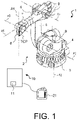
- the 1 shows an industrial robot 1 as a preferred embodiment of a machine.
- the mechanical system of the industrial robot 1 is a robot arm 2 which, in the case of the present embodiment, comprises a plurality of links as components which are arranged one after the other and are connected by means of joints.
- the links are, in particular, a stationary or movable frame 3 and a carousel 4 that is rotatably mounted relative to the frame 3 about a vertical axis A1 a preferably multi-axis robot hand 7 with a fastening device designed, for example, as a flange 8 for fastening an end effector, not shown in detail.
- the rocker 5 is mounted at the lower end, for example on a rocker bearing head not shown in detail, on the carousel 4 so as to be pivotable about a preferably horizontal axis A2.
- the cantilever 6 can in turn be pivoted about a likewise preferably horizontal axis A3 stored. This end carries the robot hand 7 with its preferably three axes A4, A5, A6.
- the industrial robot 1 or its robot arm 2 In order to move the industrial robot 1 or its robot arm 2, it comprises electric drives connected in a generally known manner to a control device 10 (robot control). In the 1 only some of the electric motors 9 of these electric drives are shown, which are attached in or on the robot arm 2 . Power electronics of the electric drives are arranged, for example, within a housing of a control cabinet, not shown in detail, within which, for example, the control device 10 is also arranged. In the case of the present exemplary embodiment, the electric motors 9 are three-phase motors, for example three-phase synchronous motors. However, the power electronics can also be arranged in and/or on the robot arm 2 .
- a computer program runs on the control device 10, by means of which the control device 10 controls the drives in an automatic mode and, if necessary, regulates them in such a way that the flange 8 of the industrial robot 1 or a tool center point TCP carries out a specified movement.
- the drives are optionally controlled electric drives.
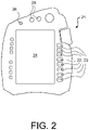
- the handheld programming device 21 is connected to the control device 10 and includes input means 22.
- the control device 10 controls the drives of the industrial robot 1 in such a way that the flange 8 or the tool center point TCP of the robot arm 2 performs a movement corresponding to the actuation of the input means 22 .
- the input means 22 include, for example, rocker switches 23 and/or a joystick, not shown in detail.
- the handheld programming device 21 can also have a display device 24 . If the display device 24 is designed as a touchscreen, the touchscreen can also be designed as an input means for the handheld programming device 21 by displaying the rocker switches 23, for example.
- the manual programming device 21 can also be used to program the industrial robot 1, ie to create the user program.
- the industrial robot 1 comprises a memory in the form of a ring memory or ring buffer 11 which is connected in particular to the control device 10 or is part of the control device 10 .
- a differently designed memory can also be provided, for example a LIFO stack or last in-first out memory or another dynamic memory.
- the ring buffer 11 is designed in particular in such a way that it overwrites the oldest stored elements in the event of an overflow.
- the industrial robot 1 is set up to be operated in a first operating mode and in a second operating mode.
- the industrial robot 1 runs in automatic mode or in manual traversing mode, ie the robot arm 1 is either moved automatically due to the user program running on the control device 1 or moved manually using the handheld programming device 21 .
- the desired operating mode can be activated, for example, by actuating further input means 25 of the manual programming device 21 .
- the industrial robot 1 or its control device 10 is set up in such a way that, during the first operating mode, the movement path covered by the robot arm 2 or its tool center point TCP is recorded continuously or in discrete steps in the memory designed as a ring buffer 11 becomes.
- the sampling rate or acquisition rate of the actual path can preferably be between 1 Hz and 10 kHz, in particular between 10 Hz and 100 Hz.
- the actual path traveled or recorded or scanned by the robot arm 2 is written to the ring buffer 11 preferably quasi-continuously.
- the recorded trajectory includes information about the tool center point TCP moved by means of the robot arm 2, in particular including information about the layers, i.e.
- the recorded trajectory can also contain information about the axis positions of the axes A1-A6, i.e. information about the relative positions of the individual links of the robot arm 2 relative to each other during the movement.
- the path of movement currently covered by the robot arm 2 is stored in the ring buffer 11 up to a length which is the length of the ring buffer 11 is specified or predetermined.
- the control device 10 controls the robot arm 2 controlled in such a way that it can be moved back and forth along the stored trajectory, in particular by means of the manual programming device 21 .
- This is preferably done by actuating the input means 22 of the handheld programming device 21, preferably by actuating one of the rocker switches 23.
- the robot arm 2 can be moved by correspondingly actuating the corresponding rocker switch 23 along the stored trajectory can be moved back and forth.
- a movement backwards to the movement carried out in the first operating mode can e.g. by pressing the part of the rocker switch 23 provided with a "-" sign and moving the robot arm 2 in the direction of the movement carried out in the first operating mode can e.g. by pressing the part with a "+” sign. Character provided part of the rocker switch 23 are selected.
- the movement covered by the robot arm 2 is not recorded in the ring buffer 21 during the second operating mode. In other words find a record the actual path in the ring buffer 21 only takes place in the first operating mode.
- the corresponding rocker switch 23 is automatically marked, for example by being illuminated or highlighted in some other way.
- a path is calculated by means of the control device 10, which e.g. represents the last forward movement driven in the first operating mode, but in the reverse direction.
- the speed of movement of the robot arm 2 during the second operating mode is preferably independent of the speed of the robot arm 2 during the first operating mode, in particular if the industrial robot 1 was in automatic mode during the first operating mode.
- the speed at which the robot arm 2 is moved in the second operating mode is preferably based on the speed or corresponds to the speed at which the robot arm 2 is moved during the manual traversing mode.
- the control device 10 preferably stops the movement of the robot arm 2 with a corresponding message.
- the rocker switch 23 is released beforehand, i.e. if the part of the rocker switch 23 marked "-" is no longer actuated before the end of the recorded movement path is reached, the movement of the robot arm 2 also stops. By actuating the rocker switch 23 again during the second operating mode, the control device 10 continues to control the robot arm 22 on the basis of the trajectory stored in the ring buffer 11 so that it moves along the stored trajectory.
- the robot arm 2 is moved in the direction of the movement carried out in the first operating mode on the basis of the movement path stored in the ring buffer 11. This happens as long as the rocker switch 23 is actuated, but at most until the point on the recorded movement path is reached at which the movement in the first operating mode was ended or at the point at which the recording of the movement path in the ring buffer 11 was ended.
- these movements carried out in the second operating mode are the only movements that are not or not completely recorded in the ring buffer 11 .
Landscapes
- Engineering & Computer Science (AREA)
- Robotics (AREA)
- Mechanical Engineering (AREA)
- Numerical Control (AREA)
- Manipulator (AREA)
Claims (13)
- Machine, présentant un mécanisme (2) qui présente au moins deux composants (3-7) agencés relativement les uns aux autres, qui sont mobiles relativement l'un à l'autre par rapport à des axes (A1-A6) au moyen d'au moins un entraînement de la machine (1), une mémoire (11), et un dispositif de commande (10) couplé à l'entraînement, qui est conçupour piloter, dans un premier mode de fonctionnement, ledit au moins un entraînement pour déplacer le mécanisme (2) de telle sorte que le mécanisme (2), en particulier un point (TCP) marqué, associé au mécanisme (2), se déplace le long d'une trajectoire de déplacement pour enregistrer, dans le premier mode de fonctionnement, la trajectoire de mouvement dans la mémoire (11), etpour piloter, dans un deuxième mode de fonctionnement, ledit au moins un entraînement sur la base de la trajectoire de déplacement enregistrée dans la mémoire (11) de telle sorte que le mécanisme (2), en particulier le point (TCP) marqué, se déplace le long de la trajectoire de déplacement enregistrée dans la mémoire (11) à l'encontre de la direction de déplacement avec laquelle le mécanisme (2) a été déplacé pendant le premier mode de fonctionnement, la vitesse de déplacement du mécanisme (2) dans le deuxième mode de fonctionnement étant différente de la vitesse de déplacement du mécanisme (2) dans le premier mode de fonctionnement, caractérisée en ce que le dispositif de commande (10) est conçu pour replanifier la courbe de vitesse pour le mouvement du mécanisme (2) pendant le deuxième mode de fonctionnement sur la base de la trajectoire de mouvement enregistrée dans la mémoire (11) et pour piloter en conséquence ledit au moins un entraînement, sans simplement lire la mémoire à rebours.
- Machine selon la revendication 1, qui est réalisée sous la forme de robot industriel (1) qui comprend un bras de robot (2) réalisé en tant que mécanisme, qui présente plusieurs composants (3-7) disposés les uns derrière les autres, reliés par des articulations, en tant que lesdits au moins deux composants, qui peuvent être déplacés les uns relativement aux autres par rapport à des axes (A1 -A6) au moyen d'entraînements associés, le dispositif de commande (10) étant conçu pour piloter, dans le premier mode de fonctionnement, les entraînements destinés à déplacer le bras de robot (2) de telle sorte que le bras de robot (2), en particulier un Tool Center Point (TCP) associé au bras de robot (2), se déplace, en tant que point marqué, le long de la trajectoire de déplacement,le dispositif de commande (10) étant conçu, dans le premier mode de fonctionnement, pour enregistrer la trajectoire de déplacement dans la mémoire (11), etle dispositif de commande (10) étant conçu, dans le deuxième mode de fonctionnement, pour piloter les entraînements sur la base de la trajectoire de déplacement enregistrée dans la mémoire (11) de telle sorte que le bras de robot (2), en particulier le Tool Center Point (TCP), se déplace le long de la trajectoire de déplacement enregistrée dans la mémoire (11).
- Machine selon la revendication 1 ou 2, dans laquelle le premier mode de fonctionnement est un fonctionnement automatique de la machine (1), dans lequel le dispositif de commande (10) pilote, sur la base d'un programme d'utilisateur fonctionnant sur le dispositif de commande (10), automatiquement ledit au moins un entraînement afin que le mécanisme (2) se déplace le long de la trajectoire de déplacement.
- Machine selon l'une des revendications 1 à 3, dont le dispositif de commande (10) est conçu, dans le deuxième mode de fonctionnement, pour piloter l'entraînement sur la base de la trajectoire de déplacement enregistrée dans la mémoire (11) de telle sorte que le mécanisme (2) se déplace en va-et-vient le long de la trajectoire de déplacement enregistrée.
- Machine selon l'une quelconque des revendications 1 à 4, présentant un dispositif d'entrée (21) couplé ou pouvant être couplé au dispositif de commande (10), qui présente des moyens d'entrée (22) et, dans le deuxième mode de fonctionnement, le dispositif de commande (10) pilote l'entraînement pour déplacer le mécanisme (2) le long de la trajectoire de déplacement enregistrée dans la mémoire (11), en fonction d'un actionnement manuel des moyens d'entrée (22).
- Machine selon l'une quelconque des revendications 1 à 5, dont le dispositif de commande (10) est conçu, pendant le premier mode de fonctionnement, pour terminer, sur la base d'un actionnement d'un moyen d'entrée (26), l'enregistrement de la trajectoire de déplacement actuel dans la mémoire (11) et, après avoir terminé l'enregistrement de la trajectoire de mouvement dans le premier mode de fonctionnement, pour continuer à déplacer le mécanisme (2), et dont le dispositif de commande (10) est conçu, pendant le deuxième mode de fonctionnement, pour déplacer automatiquement le mécanisme (2), vers le début ou vers la fin de la trajectoire de déplacement enregistrée dans la mémoire (11), de telle sorte que le mécanisme (2) est apte à se déplacer le long de la trajectoire de déplacement enregistrée dans la mémoire (11).
- Machine selon l'une des revendications précédentes, dans laquelle la mémoire (11) est conçue comme une mémoire tampon circulaire ou comme une mémoire LIFO.
- Procédé pour faire fonctionner une machine (1) qui présente un dispositif de commande (10) et un mécanisme (2) qui présente au moins deux composants (3-7) disposés les uns par rapport aux autres, qui sont mobiles relativement les uns aux autres par rapport à un axe (A1-A6) au moyen d'au moins un entraînement de la machine (1), présentant les étapes de procédé suivantes :- dans un premier mode de fonctionnement de la machine (1), pilotage dudit au moins un entraînement au moyen du dispositif de commande (10) de telle sorte que le mécanisme (2), en particulier un point (TCP) marqué, associé au mécanisme (2), se déplace le long d'une trajectoire de déplacement, et simultanément, enregistrement de la trajectoire de déplacement dans une mémoire (11), et- dans un deuxième mode de fonctionnement de la machine (1), pilotage dudit au moins un entraînement au moyen du dispositif de commande (10), sur la base de la trajectoire de déplacement enregistrée dans la mémoire (11) de telle sorte que le mécanisme (2) se déplace le long de la trajectoire de déplacement enregistrée dans la mémoire (11) à l'encontre de la direction de déplacement avec laquelle le mécanisme (2) a été déplacé pendant le premier mode de fonctionnement, et- dans le deuxième mode de fonctionnement, déplacement du mécanisme (2) le long de la trajectoire de déplacement enregistrée dans la mémoire (11) à une vitesse qui est différente de la vitesse à laquelle le mécanisme (2) a été déplacé dans le premier mode de fonctionnement,caractérisé par l'étape supplémentaire consistant à replanifier la courbe de vitesse pour le déplacement du mécanisme (2) pendant le deuxième mode de fonctionnement sur la base de la trajectoire de déplacement enregistrée dans la mémoire (11) par le dispositif de commande (10) et à piloter ledit au moins en conséquence un entraînement, sans simplement lire la mémoire à rebours.
- Procédé selon la revendication 8, dans lequel la machine est réalisée sous la forme d'un robot industriel (1) qui présente comme mécanisme un bras de robot (2) qui comprend plusieurs éléments (3-7) disposés les uns derrière les autres et reliés par des articulations, en tant que lesdits au moins deux composants, et en particulier le point marqué est un Tool Center Point (TCP) associé au bras de robot (2).
- Procédé selon la revendication 9 ou 8, dans lequel le premier mode de fonctionnement est un fonctionnement automatique de la machine (1), dans lequel le dispositif de commande (10) pilote automatiquement, sur la base d'un programme d'utilisateur fonctionnant sur le dispositif de commande (10), ledit au moins un entraînement afin que le mécanisme (2) se déplace le long de la trajectoire de déplacement, et/ou dans lequel le premier mode de fonctionnement constitue un mode de déplacement manuel de la machine (1), et la machine (1) comprend un dispositif d'entrée (21) couplé ou pouvant être couplé au dispositif de commande (10), qui présente des moyens d'entrée (22), et dans le mode de déplacement manuel, le dispositif de commande (10) pilote l'entraînement pour le déplacement du mécanisme (2) le long de la trajectoire de déplacement conformément à un actionnement manuel des moyens d'entrée (22).
- Procédé selon l'une des revendications 8 à 10, et/ou présentant le pilotage de l'entraînement au moyen du dispositif de commande (10) dans le deuxième mode de fonctionnement, sur la base de la trajectoire de déplacement enregistrée dans la mémoire (11), de telle sorte que le mécanisme (2) se déplace en va-et-vient le long de la trajectoire de déplacement enregistrée.
- Procédé selon l'une quelconque des revendications 8 à 11, présentant le pilotage de l'entraînement au moyen du dispositif de commande (10), sur la base de la trajectoire de déplacement enregistrée dans la mémoire (11) et en fonction d'un actionnement de moyens d'entrée (22) d'un dispositif d'entrée (21) .
- Procédé selon l'une quelconque des revendications 8 à 12, présentant la terminaison de l'enregistrement de la trajectoire dans la mémoire (11) pendant le premier mode de fonctionnement, en particulier sur la base d'un actionnement d'un moyen d'entrée (26), et la poursuite du déplacement du mécanisme (2), dans le premier mode de fonctionnement, et le rapprochement automatique du mécanisme (2) vers le début ou vers la fin de la trajectoire enregistrée dans la mémoire (11), dans le deuxième mode de fonctionnement, de telle sorte que le mécanisme (2) est apte à se déplacer le long de la trajectoire enregistrée dans la mémoire (11).
Applications Claiming Priority (2)
| Application Number | Priority Date | Filing Date | Title |
|---|---|---|---|
| DE102014213262.2A DE102014213262A1 (de) | 2014-07-08 | 2014-07-08 | Maschine und Verfahren zum Betreiben einer Maschine |
| PCT/EP2015/065461 WO2016005379A1 (fr) | 2014-07-08 | 2015-07-07 | Machine et procédé permettant de faire fonctionner une machine |
Publications (2)
| Publication Number | Publication Date |
|---|---|
| EP3166759A1 EP3166759A1 (fr) | 2017-05-17 |
| EP3166759B1 true EP3166759B1 (fr) | 2022-07-27 |
Family
ID=53525185
Family Applications (1)
| Application Number | Title | Priority Date | Filing Date |
|---|---|---|---|
| EP15735676.7A Active EP3166759B1 (fr) | 2014-07-08 | 2015-07-07 | Machine et procédé permettant de faire fonctionner une machine |
Country Status (6)
| Country | Link |
|---|---|
| US (1) | US20170197310A1 (fr) |
| EP (1) | EP3166759B1 (fr) |
| KR (1) | KR20170018384A (fr) |
| CN (1) | CN106488832A (fr) |
| DE (1) | DE102014213262A1 (fr) |
| WO (1) | WO2016005379A1 (fr) |
Families Citing this family (7)
| Publication number | Priority date | Publication date | Assignee | Title |
|---|---|---|---|---|
| JP6778199B2 (ja) * | 2015-08-25 | 2020-10-28 | 川崎重工業株式会社 | 遠隔操作ロボットシステム |
| DE102017010244A1 (de) | 2017-11-03 | 2019-05-09 | Kuka Deutschland Gmbh | Verfahren und Steuermittel zum Steuern einer Roboteranordnung |
| CN108789415B (zh) * | 2018-07-27 | 2021-05-28 | 珠海格力智能装备有限公司 | 机器人及其运动轨迹数据的存储方法和装置 |
| CN109465826B (zh) * | 2018-11-13 | 2021-08-17 | 南京工程学院 | 一种基于姿态均匀分布的工业机器人tcp标定方法 |
| CN112436431B (zh) * | 2020-11-30 | 2022-03-25 | 国网湖北省电力有限公司检修公司 | 带电更换特高压线路绝缘子机器人控制系统及方法 |
| JP7593078B2 (ja) * | 2020-11-30 | 2024-12-03 | セイコーエプソン株式会社 | モーター制御用角度センサー、モーター制御システムおよびモーター制御用角度センサーの制御方法 |
| CN113650015B (zh) * | 2021-08-20 | 2022-07-26 | 中国人民解放军63920部队 | 一种月面采样机械臂动态任务规划方法 |
Family Cites Families (13)
| Publication number | Priority date | Publication date | Assignee | Title |
|---|---|---|---|---|
| US3920972A (en) * | 1974-07-16 | 1975-11-18 | Cincinnati Milacron Inc | Method and apparatus for programming a computer operated robot arm |
| DE3724428A1 (de) * | 1987-07-23 | 1989-02-02 | Christian Loeffler | Verfahren zur direkten speicherung eines bewegungsablaufes in echtzeit und exakter wiedergabe dieser bewegung sowohl in zeit als auch ort |
| JP3276248B2 (ja) * | 1994-08-02 | 2002-04-22 | 株式会社小松製作所 | 異常復帰装置 |
| EP0850730B1 (fr) * | 1995-09-14 | 2002-07-24 | Kabushiki Kaisha Yaskawa Denki | Unite d'enseignement pour robots |
| JP4014662B2 (ja) * | 1995-09-18 | 2007-11-28 | ファナック株式会社 | ロボット教示操作盤 |
| JPH1011124A (ja) * | 1996-06-20 | 1998-01-16 | Fanuc Ltd | ロボットの後退実行機能を備えたロボット制御装置 |
| SE525108C2 (sv) * | 2002-12-30 | 2004-11-30 | Abb Research Ltd | Metod och system för programmering av en industrirobot, datorprogramprodukt, datorläsbart medium samt användning |
| SE531104C2 (sv) * | 2002-12-30 | 2008-12-16 | Abb Research Ltd | Metod och system för programmering av en industrirobot |
| JP4027350B2 (ja) * | 2004-06-29 | 2007-12-26 | ファナック株式会社 | ロボットの待機位置復帰プログラム作成装置 |
| US9393691B2 (en) * | 2009-02-12 | 2016-07-19 | Mitsubishi Electric Corporation | Industrial robot system including action planning circuitry for temporary halts |
| CN201559195U (zh) * | 2009-12-11 | 2010-08-25 | Abb技术有限公司 | 机器人 |
| US8340820B2 (en) * | 2010-02-26 | 2012-12-25 | Agilent Technologies, Inc. | Robot arm and method of controlling robot arm to avoid collisions |
| DE102012009010A1 (de) * | 2012-05-05 | 2012-12-13 | Daimler Ag | Verfahren zum Erzeugen einer Bewegung eines Roboters |
-
2014
- 2014-07-08 DE DE102014213262.2A patent/DE102014213262A1/de not_active Ceased
-
2015
- 2015-07-07 CN CN201580037347.6A patent/CN106488832A/zh active Pending
- 2015-07-07 US US15/324,493 patent/US20170197310A1/en not_active Abandoned
- 2015-07-07 KR KR1020177000465A patent/KR20170018384A/ko not_active Ceased
- 2015-07-07 WO PCT/EP2015/065461 patent/WO2016005379A1/fr not_active Ceased
- 2015-07-07 EP EP15735676.7A patent/EP3166759B1/fr active Active
Also Published As
| Publication number | Publication date |
|---|---|
| WO2016005379A1 (fr) | 2016-01-14 |
| US20170197310A1 (en) | 2017-07-13 |
| DE102014213262A1 (de) | 2016-01-14 |
| CN106488832A (zh) | 2017-03-08 |
| KR20170018384A (ko) | 2017-02-17 |
| EP3166759A1 (fr) | 2017-05-17 |
Similar Documents
| Publication | Publication Date | Title |
|---|---|---|
| EP3166759B1 (fr) | Machine et procédé permettant de faire fonctionner une machine | |
| EP2255931B1 (fr) | Procédé et dispositif de commande d'un manipulateur | |
| EP1950010B1 (fr) | Robot et procédé de programmation d'un robot | |
| DE102018122376B3 (de) | Verfahren und Vorrichtung zur kollisionsfreien Bewegungsplanung eines Manipulators | |
| EP2546711B1 (fr) | Procédé de programmation d'un robot | |
| EP2987592B1 (fr) | Procede de programmation d'un robot industriel et robot industriel correspondant | |
| EP2223191B1 (fr) | Robot industriel et procédé de programmation d'un robot industriel | |
| EP2303521B1 (fr) | Robot industriel et procédé de planification de trajectoire pour commander le déplacement d un robot industriel | |
| DE2530261C2 (de) | Programmiereinrichtung für einen Manipulator | |
| EP2492062B2 (fr) | Robot industriel | |
| DE102010039540C5 (de) | Handbediengerät zum manuellen Bewegen eines Roboterarms | |
| DE112019006713B4 (de) | Ein Verfahren zur Steuerung einer Bewegung, eine Bewegungssteuereinrichtung und ein System sowie ein Speichermedium desselben | |
| EP2353802A2 (fr) | Procédé de planification de bande sans collision d'un robot industriel | |
| WO2018228727A1 (fr) | Installation de traitement de récipient équipée d'un robot mobile pour le changement de composant | |
| DE102015114013B4 (de) | Verfahren und Vorrichtung zur Steuerung des Betriebs eines Roboters | |
| DE102007026299B4 (de) | Industrieroboter und Verfahren zum Programmieren eines Industrieroboters | |
| DE10255037A1 (de) | Verfahren und Vorrichtung zum Bearbeiten eines Werkstücks | |
| WO2016206968A1 (fr) | Procédé de planification optimisé en termes de redondance d'un fonctionnement d'un robot mobile | |
| EP1906281A1 (fr) | Procédé et système pour la conception et la vérification de zones de sécurité d'un robot industriel | |
| EP3569367B1 (fr) | Détermination d'un mouvement d'un dispositif assistée par ordinateur | |
| EP3112094A1 (fr) | Procédé de commande d'un système de manipulation | |
| EP2008778A1 (fr) | Procédé et dispositif destinés à la programmation d'un robot industriel | |
| EP2208584A1 (fr) | Procédé et dispositif destinés à la commande de robots industriels | |
| EP2504741B1 (fr) | Procédé d'élaboration d'un modèle de robot, et robot industriel | |
| EP4084937B1 (fr) | Déplacement d'une référence fixée à un robot |
Legal Events
| Date | Code | Title | Description |
|---|---|---|---|
| STAA | Information on the status of an ep patent application or granted ep patent |
Free format text: STATUS: THE INTERNATIONAL PUBLICATION HAS BEEN MADE |
|
| PUAI | Public reference made under article 153(3) epc to a published international application that has entered the european phase |
Free format text: ORIGINAL CODE: 0009012 |
|
| STAA | Information on the status of an ep patent application or granted ep patent |
Free format text: STATUS: REQUEST FOR EXAMINATION WAS MADE |
|
| 17P | Request for examination filed |
Effective date: 20161215 |
|
| AK | Designated contracting states |
Kind code of ref document: A1 Designated state(s): AL AT BE BG CH CY CZ DE DK EE ES FI FR GB GR HR HU IE IS IT LI LT LU LV MC MK MT NL NO PL PT RO RS SE SI SK SM TR |
|
| AX | Request for extension of the european patent |
Extension state: BA ME |
|
| DAV | Request for validation of the european patent (deleted) | ||
| DAX | Request for extension of the european patent (deleted) | ||
| RAP1 | Party data changed (applicant data changed or rights of an application transferred) |
Owner name: KUKA DEUTSCHLAND GMBH |
|
| STAA | Information on the status of an ep patent application or granted ep patent |
Free format text: STATUS: EXAMINATION IS IN PROGRESS |
|
| 17Q | First examination report despatched |
Effective date: 20200420 |
|
| GRAP | Despatch of communication of intention to grant a patent |
Free format text: ORIGINAL CODE: EPIDOSNIGR1 |
|
| STAA | Information on the status of an ep patent application or granted ep patent |
Free format text: STATUS: GRANT OF PATENT IS INTENDED |
|
| INTG | Intention to grant announced |
Effective date: 20220303 |
|
| GRAS | Grant fee paid |
Free format text: ORIGINAL CODE: EPIDOSNIGR3 |
|
| GRAA | (expected) grant |
Free format text: ORIGINAL CODE: 0009210 |
|
| STAA | Information on the status of an ep patent application or granted ep patent |
Free format text: STATUS: THE PATENT HAS BEEN GRANTED |
|
| AK | Designated contracting states |
Kind code of ref document: B1 Designated state(s): AL AT BE BG CH CY CZ DE DK EE ES FI FR GB GR HR HU IE IS IT LI LT LU LV MC MK MT NL NO PL PT RO RS SE SI SK SM TR |
|
| REG | Reference to a national code |
Ref country code: CH Ref legal event code: EP |
|
| REG | Reference to a national code |
Ref country code: AT Ref legal event code: REF Ref document number: 1506768 Country of ref document: AT Kind code of ref document: T Effective date: 20220815 |
|
| REG | Reference to a national code |
Ref country code: DE Ref legal event code: R096 Ref document number: 502015015971 Country of ref document: DE |
|
| REG | Reference to a national code |
Ref country code: IE Ref legal event code: FG4D Free format text: LANGUAGE OF EP DOCUMENT: GERMAN |
|
| REG | Reference to a national code |
Ref country code: LT Ref legal event code: MG9D |
|
| REG | Reference to a national code |
Ref country code: NL Ref legal event code: MP Effective date: 20220727 |
|
| PG25 | Lapsed in a contracting state [announced via postgrant information from national office to epo] |
Ref country code: SE Free format text: LAPSE BECAUSE OF FAILURE TO SUBMIT A TRANSLATION OF THE DESCRIPTION OR TO PAY THE FEE WITHIN THE PRESCRIBED TIME-LIMIT Effective date: 20220727 Ref country code: RS Free format text: LAPSE BECAUSE OF FAILURE TO SUBMIT A TRANSLATION OF THE DESCRIPTION OR TO PAY THE FEE WITHIN THE PRESCRIBED TIME-LIMIT Effective date: 20220727 Ref country code: PT Free format text: LAPSE BECAUSE OF FAILURE TO SUBMIT A TRANSLATION OF THE DESCRIPTION OR TO PAY THE FEE WITHIN THE PRESCRIBED TIME-LIMIT Effective date: 20221128 Ref country code: NO Free format text: LAPSE BECAUSE OF FAILURE TO SUBMIT A TRANSLATION OF THE DESCRIPTION OR TO PAY THE FEE WITHIN THE PRESCRIBED TIME-LIMIT Effective date: 20221027 Ref country code: NL Free format text: LAPSE BECAUSE OF FAILURE TO SUBMIT A TRANSLATION OF THE DESCRIPTION OR TO PAY THE FEE WITHIN THE PRESCRIBED TIME-LIMIT Effective date: 20220727 Ref country code: LV Free format text: LAPSE BECAUSE OF FAILURE TO SUBMIT A TRANSLATION OF THE DESCRIPTION OR TO PAY THE FEE WITHIN THE PRESCRIBED TIME-LIMIT Effective date: 20220727 Ref country code: LT Free format text: LAPSE BECAUSE OF FAILURE TO SUBMIT A TRANSLATION OF THE DESCRIPTION OR TO PAY THE FEE WITHIN THE PRESCRIBED TIME-LIMIT Effective date: 20220727 Ref country code: FI Free format text: LAPSE BECAUSE OF FAILURE TO SUBMIT A TRANSLATION OF THE DESCRIPTION OR TO PAY THE FEE WITHIN THE PRESCRIBED TIME-LIMIT Effective date: 20220727 Ref country code: ES Free format text: LAPSE BECAUSE OF FAILURE TO SUBMIT A TRANSLATION OF THE DESCRIPTION OR TO PAY THE FEE WITHIN THE PRESCRIBED TIME-LIMIT Effective date: 20220727 |
|
| PG25 | Lapsed in a contracting state [announced via postgrant information from national office to epo] |
Ref country code: PL Free format text: LAPSE BECAUSE OF FAILURE TO SUBMIT A TRANSLATION OF THE DESCRIPTION OR TO PAY THE FEE WITHIN THE PRESCRIBED TIME-LIMIT Effective date: 20220727 Ref country code: IS Free format text: LAPSE BECAUSE OF FAILURE TO SUBMIT A TRANSLATION OF THE DESCRIPTION OR TO PAY THE FEE WITHIN THE PRESCRIBED TIME-LIMIT Effective date: 20221127 Ref country code: HR Free format text: LAPSE BECAUSE OF FAILURE TO SUBMIT A TRANSLATION OF THE DESCRIPTION OR TO PAY THE FEE WITHIN THE PRESCRIBED TIME-LIMIT Effective date: 20220727 Ref country code: GR Free format text: LAPSE BECAUSE OF FAILURE TO SUBMIT A TRANSLATION OF THE DESCRIPTION OR TO PAY THE FEE WITHIN THE PRESCRIBED TIME-LIMIT Effective date: 20221028 |
|
| PG25 | Lapsed in a contracting state [announced via postgrant information from national office to epo] |
Ref country code: SM Free format text: LAPSE BECAUSE OF FAILURE TO SUBMIT A TRANSLATION OF THE DESCRIPTION OR TO PAY THE FEE WITHIN THE PRESCRIBED TIME-LIMIT Effective date: 20220727 Ref country code: RO Free format text: LAPSE BECAUSE OF FAILURE TO SUBMIT A TRANSLATION OF THE DESCRIPTION OR TO PAY THE FEE WITHIN THE PRESCRIBED TIME-LIMIT Effective date: 20220727 Ref country code: DK Free format text: LAPSE BECAUSE OF FAILURE TO SUBMIT A TRANSLATION OF THE DESCRIPTION OR TO PAY THE FEE WITHIN THE PRESCRIBED TIME-LIMIT Effective date: 20220727 Ref country code: CZ Free format text: LAPSE BECAUSE OF FAILURE TO SUBMIT A TRANSLATION OF THE DESCRIPTION OR TO PAY THE FEE WITHIN THE PRESCRIBED TIME-LIMIT Effective date: 20220727 |
|
| REG | Reference to a national code |
Ref country code: DE Ref legal event code: R097 Ref document number: 502015015971 Country of ref document: DE |
|
| PG25 | Lapsed in a contracting state [announced via postgrant information from national office to epo] |
Ref country code: SK Free format text: LAPSE BECAUSE OF FAILURE TO SUBMIT A TRANSLATION OF THE DESCRIPTION OR TO PAY THE FEE WITHIN THE PRESCRIBED TIME-LIMIT Effective date: 20220727 Ref country code: EE Free format text: LAPSE BECAUSE OF FAILURE TO SUBMIT A TRANSLATION OF THE DESCRIPTION OR TO PAY THE FEE WITHIN THE PRESCRIBED TIME-LIMIT Effective date: 20220727 |
|
| PLBE | No opposition filed within time limit |
Free format text: ORIGINAL CODE: 0009261 |
|
| STAA | Information on the status of an ep patent application or granted ep patent |
Free format text: STATUS: NO OPPOSITION FILED WITHIN TIME LIMIT |
|
| PG25 | Lapsed in a contracting state [announced via postgrant information from national office to epo] |
Ref country code: AL Free format text: LAPSE BECAUSE OF FAILURE TO SUBMIT A TRANSLATION OF THE DESCRIPTION OR TO PAY THE FEE WITHIN THE PRESCRIBED TIME-LIMIT Effective date: 20220727 |
|
| 26N | No opposition filed |
Effective date: 20230502 |
|
| P01 | Opt-out of the competence of the unified patent court (upc) registered |
Effective date: 20230528 |
|
| PG25 | Lapsed in a contracting state [announced via postgrant information from national office to epo] |
Ref country code: SI Free format text: LAPSE BECAUSE OF FAILURE TO SUBMIT A TRANSLATION OF THE DESCRIPTION OR TO PAY THE FEE WITHIN THE PRESCRIBED TIME-LIMIT Effective date: 20220727 |
|
| PG25 | Lapsed in a contracting state [announced via postgrant information from national office to epo] |
Ref country code: MC Free format text: LAPSE BECAUSE OF FAILURE TO SUBMIT A TRANSLATION OF THE DESCRIPTION OR TO PAY THE FEE WITHIN THE PRESCRIBED TIME-LIMIT Effective date: 20220727 |
|
| PG25 | Lapsed in a contracting state [announced via postgrant information from national office to epo] |
Ref country code: MC Free format text: LAPSE BECAUSE OF FAILURE TO SUBMIT A TRANSLATION OF THE DESCRIPTION OR TO PAY THE FEE WITHIN THE PRESCRIBED TIME-LIMIT Effective date: 20220727 |
|
| REG | Reference to a national code |
Ref country code: BE Ref legal event code: MM Effective date: 20230731 |
|
| PG25 | Lapsed in a contracting state [announced via postgrant information from national office to epo] |
Ref country code: LU Free format text: LAPSE BECAUSE OF NON-PAYMENT OF DUE FEES Effective date: 20230707 |
|
| PG25 | Lapsed in a contracting state [announced via postgrant information from national office to epo] |
Ref country code: LU Free format text: LAPSE BECAUSE OF NON-PAYMENT OF DUE FEES Effective date: 20230707 |
|
| REG | Reference to a national code |
Ref country code: IE Ref legal event code: MM4A |
|
| PG25 | Lapsed in a contracting state [announced via postgrant information from national office to epo] |
Ref country code: IT Free format text: LAPSE BECAUSE OF FAILURE TO SUBMIT A TRANSLATION OF THE DESCRIPTION OR TO PAY THE FEE WITHIN THE PRESCRIBED TIME-LIMIT Effective date: 20220727 Ref country code: BE Free format text: LAPSE BECAUSE OF NON-PAYMENT OF DUE FEES Effective date: 20230731 |
|
| PG25 | Lapsed in a contracting state [announced via postgrant information from national office to epo] |
Ref country code: IE Free format text: LAPSE BECAUSE OF NON-PAYMENT OF DUE FEES Effective date: 20230707 |
|
| PG25 | Lapsed in a contracting state [announced via postgrant information from national office to epo] |
Ref country code: IE Free format text: LAPSE BECAUSE OF NON-PAYMENT OF DUE FEES Effective date: 20230707 |
|
| PG25 | Lapsed in a contracting state [announced via postgrant information from national office to epo] |
Ref country code: BG Free format text: LAPSE BECAUSE OF FAILURE TO SUBMIT A TRANSLATION OF THE DESCRIPTION OR TO PAY THE FEE WITHIN THE PRESCRIBED TIME-LIMIT Effective date: 20220727 |
|
| PG25 | Lapsed in a contracting state [announced via postgrant information from national office to epo] |
Ref country code: BG Free format text: LAPSE BECAUSE OF FAILURE TO SUBMIT A TRANSLATION OF THE DESCRIPTION OR TO PAY THE FEE WITHIN THE PRESCRIBED TIME-LIMIT Effective date: 20220727 |
|
| PGFP | Annual fee paid to national office [announced via postgrant information from national office to epo] |
Ref country code: GB Payment date: 20250529 Year of fee payment: 11 |
|
| PGFP | Annual fee paid to national office [announced via postgrant information from national office to epo] |
Ref country code: FR Payment date: 20250610 Year of fee payment: 11 |
|
| PG25 | Lapsed in a contracting state [announced via postgrant information from national office to epo] |
Ref country code: CY Free format text: LAPSE BECAUSE OF FAILURE TO SUBMIT A TRANSLATION OF THE DESCRIPTION OR TO PAY THE FEE WITHIN THE PRESCRIBED TIME-LIMIT; INVALID AB INITIO Effective date: 20150707 |
|
| PG25 | Lapsed in a contracting state [announced via postgrant information from national office to epo] |
Ref country code: HU Free format text: LAPSE BECAUSE OF FAILURE TO SUBMIT A TRANSLATION OF THE DESCRIPTION OR TO PAY THE FEE WITHIN THE PRESCRIBED TIME-LIMIT; INVALID AB INITIO Effective date: 20150707 |
|
| PGFP | Annual fee paid to national office [announced via postgrant information from national office to epo] |
Ref country code: DE Payment date: 20250604 Year of fee payment: 11 |
|
| PGFP | Annual fee paid to national office [announced via postgrant information from national office to epo] |
Ref country code: AT Payment date: 20250625 Year of fee payment: 11 |
|
| PGFP | Annual fee paid to national office [announced via postgrant information from national office to epo] |
Ref country code: CH Payment date: 20250801 Year of fee payment: 11 |
|
| PG25 | Lapsed in a contracting state [announced via postgrant information from national office to epo] |
Ref country code: TR Free format text: LAPSE BECAUSE OF FAILURE TO SUBMIT A TRANSLATION OF THE DESCRIPTION OR TO PAY THE FEE WITHIN THE PRESCRIBED TIME-LIMIT Effective date: 20220727 |