EP3170216B1 - Lithium-schwefel-batterie - Google Patents
Lithium-schwefel-batterie Download PDFInfo
- Publication number
- EP3170216B1 EP3170216B1 EP15748294.4A EP15748294A EP3170216B1 EP 3170216 B1 EP3170216 B1 EP 3170216B1 EP 15748294 A EP15748294 A EP 15748294A EP 3170216 B1 EP3170216 B1 EP 3170216B1
- Authority
- EP
- European Patent Office
- Prior art keywords
- lithium
- separator
- electrolyte
- stage
- battery according
- Prior art date
- Legal status (The legal status is an assumption and is not a legal conclusion. Google has not performed a legal analysis and makes no representation as to the accuracy of the status listed.)
- Active
Links
Images

Classifications
-
- H—ELECTRICITY
- H01—ELECTRIC ELEMENTS
- H01M—PROCESSES OR MEANS, e.g. BATTERIES, FOR THE DIRECT CONVERSION OF CHEMICAL ENERGY INTO ELECTRICAL ENERGY
- H01M50/00—Constructional details or processes of manufacture of the non-active parts of electrochemical cells other than fuel cells, e.g. hybrid cells
- H01M50/40—Separators; Membranes; Diaphragms; Spacing elements inside cells
- H01M50/409—Separators, membranes or diaphragms characterised by the material
- H01M50/411—Organic material
-
- H—ELECTRICITY
- H01—ELECTRIC ELEMENTS
- H01M—PROCESSES OR MEANS, e.g. BATTERIES, FOR THE DIRECT CONVERSION OF CHEMICAL ENERGY INTO ELECTRICAL ENERGY
- H01M4/00—Electrodes
- H01M4/02—Electrodes composed of, or comprising, active material
- H01M4/36—Selection of substances as active materials, active masses, active liquids
- H01M4/58—Selection of substances as active materials, active masses, active liquids of inorganic compounds other than oxides or hydroxides, e.g. sulfides, selenides, tellurides, halogenides or LiCoFy; of polyanionic structures, e.g. phosphates, silicates or borates
- H01M4/581—Chalcogenides or intercalation compounds thereof
- H01M4/5815—Sulfides
-
- H—ELECTRICITY
- H01—ELECTRIC ELEMENTS
- H01M—PROCESSES OR MEANS, e.g. BATTERIES, FOR THE DIRECT CONVERSION OF CHEMICAL ENERGY INTO ELECTRICAL ENERGY
- H01M10/00—Secondary cells; Manufacture thereof
- H01M10/05—Accumulators with non-aqueous electrolyte
- H01M10/052—Li-accumulators
-
- H—ELECTRICITY
- H01—ELECTRIC ELEMENTS
- H01M—PROCESSES OR MEANS, e.g. BATTERIES, FOR THE DIRECT CONVERSION OF CHEMICAL ENERGY INTO ELECTRICAL ENERGY
- H01M10/00—Secondary cells; Manufacture thereof
- H01M10/05—Accumulators with non-aqueous electrolyte
- H01M10/052—Li-accumulators
- H01M10/0525—Rocking-chair batteries, i.e. batteries with lithium insertion or intercalation in both electrodes; Lithium-ion batteries
-
- H—ELECTRICITY
- H01—ELECTRIC ELEMENTS
- H01M—PROCESSES OR MEANS, e.g. BATTERIES, FOR THE DIRECT CONVERSION OF CHEMICAL ENERGY INTO ELECTRICAL ENERGY
- H01M10/00—Secondary cells; Manufacture thereof
- H01M10/05—Accumulators with non-aqueous electrolyte
- H01M10/056—Accumulators with non-aqueous electrolyte characterised by the materials used as electrolytes, e.g. mixed inorganic/organic electrolytes
- H01M10/0564—Accumulators with non-aqueous electrolyte characterised by the materials used as electrolytes, e.g. mixed inorganic/organic electrolytes the electrolyte being constituted of organic materials only
- H01M10/0565—Polymeric materials, e.g. gel-type or solid-type
-
- H—ELECTRICITY
- H01—ELECTRIC ELEMENTS
- H01M—PROCESSES OR MEANS, e.g. BATTERIES, FOR THE DIRECT CONVERSION OF CHEMICAL ENERGY INTO ELECTRICAL ENERGY
- H01M10/00—Secondary cells; Manufacture thereof
- H01M10/05—Accumulators with non-aqueous electrolyte
- H01M10/056—Accumulators with non-aqueous electrolyte characterised by the materials used as electrolytes, e.g. mixed inorganic/organic electrolytes
- H01M10/0564—Accumulators with non-aqueous electrolyte characterised by the materials used as electrolytes, e.g. mixed inorganic/organic electrolytes the electrolyte being constituted of organic materials only
- H01M10/0566—Liquid materials
- H01M10/0568—Liquid materials characterised by the solutes
-
- H—ELECTRICITY
- H01—ELECTRIC ELEMENTS
- H01M—PROCESSES OR MEANS, e.g. BATTERIES, FOR THE DIRECT CONVERSION OF CHEMICAL ENERGY INTO ELECTRICAL ENERGY
- H01M10/00—Secondary cells; Manufacture thereof
- H01M10/05—Accumulators with non-aqueous electrolyte
- H01M10/056—Accumulators with non-aqueous electrolyte characterised by the materials used as electrolytes, e.g. mixed inorganic/organic electrolytes
- H01M10/0564—Accumulators with non-aqueous electrolyte characterised by the materials used as electrolytes, e.g. mixed inorganic/organic electrolytes the electrolyte being constituted of organic materials only
- H01M10/0566—Liquid materials
- H01M10/0569—Liquid materials characterised by the solvents
-
- H—ELECTRICITY
- H01—ELECTRIC ELEMENTS
- H01M—PROCESSES OR MEANS, e.g. BATTERIES, FOR THE DIRECT CONVERSION OF CHEMICAL ENERGY INTO ELECTRICAL ENERGY
- H01M4/00—Electrodes
- H01M4/02—Electrodes composed of, or comprising, active material
- H01M4/36—Selection of substances as active materials, active masses, active liquids
- H01M4/38—Selection of substances as active materials, active masses, active liquids of elements or alloys
-
- H—ELECTRICITY
- H01—ELECTRIC ELEMENTS
- H01M—PROCESSES OR MEANS, e.g. BATTERIES, FOR THE DIRECT CONVERSION OF CHEMICAL ENERGY INTO ELECTRICAL ENERGY
- H01M4/00—Electrodes
- H01M4/02—Electrodes composed of, or comprising, active material
- H01M4/36—Selection of substances as active materials, active masses, active liquids
- H01M4/38—Selection of substances as active materials, active masses, active liquids of elements or alloys
- H01M4/381—Alkaline or alkaline earth metals elements
- H01M4/382—Lithium
-
- H—ELECTRICITY
- H01—ELECTRIC ELEMENTS
- H01M—PROCESSES OR MEANS, e.g. BATTERIES, FOR THE DIRECT CONVERSION OF CHEMICAL ENERGY INTO ELECTRICAL ENERGY
- H01M4/00—Electrodes
- H01M4/02—Electrodes composed of, or comprising, active material
- H01M4/62—Selection of inactive substances as ingredients for active masses, e.g. binders, fillers
- H01M4/621—Binders
- H01M4/622—Binders being polymers
-
- H—ELECTRICITY
- H01—ELECTRIC ELEMENTS
- H01M—PROCESSES OR MEANS, e.g. BATTERIES, FOR THE DIRECT CONVERSION OF CHEMICAL ENERGY INTO ELECTRICAL ENERGY
- H01M4/00—Electrodes
- H01M4/02—Electrodes composed of, or comprising, active material
- H01M4/62—Selection of inactive substances as ingredients for active masses, e.g. binders, fillers
- H01M4/624—Electric conductive fillers
- H01M4/625—Carbon or graphite
-
- H—ELECTRICITY
- H01—ELECTRIC ELEMENTS
- H01M—PROCESSES OR MEANS, e.g. BATTERIES, FOR THE DIRECT CONVERSION OF CHEMICAL ENERGY INTO ELECTRICAL ENERGY
- H01M50/00—Constructional details or processes of manufacture of the non-active parts of electrochemical cells other than fuel cells, e.g. hybrid cells
- H01M50/40—Separators; Membranes; Diaphragms; Spacing elements inside cells
- H01M50/409—Separators, membranes or diaphragms characterised by the material
- H01M50/411—Organic material
- H01M50/414—Synthetic resins, e.g. thermoplastics or thermosetting resins
- H01M50/417—Polyolefins
-
- H—ELECTRICITY
- H01—ELECTRIC ELEMENTS
- H01M—PROCESSES OR MEANS, e.g. BATTERIES, FOR THE DIRECT CONVERSION OF CHEMICAL ENERGY INTO ELECTRICAL ENERGY
- H01M50/00—Constructional details or processes of manufacture of the non-active parts of electrochemical cells other than fuel cells, e.g. hybrid cells
- H01M50/40—Separators; Membranes; Diaphragms; Spacing elements inside cells
- H01M50/489—Separators, membranes, diaphragms or spacing elements inside the cells, characterised by their physical properties, e.g. swelling degree, hydrophilicity or shut down properties
-
- H—ELECTRICITY
- H01—ELECTRIC ELEMENTS
- H01M—PROCESSES OR MEANS, e.g. BATTERIES, FOR THE DIRECT CONVERSION OF CHEMICAL ENERGY INTO ELECTRICAL ENERGY
- H01M50/00—Constructional details or processes of manufacture of the non-active parts of electrochemical cells other than fuel cells, e.g. hybrid cells
- H01M50/40—Separators; Membranes; Diaphragms; Spacing elements inside cells
- H01M50/489—Separators, membranes, diaphragms or spacing elements inside the cells, characterised by their physical properties, e.g. swelling degree, hydrophilicity or shut down properties
- H01M50/491—Porosity
-
- H—ELECTRICITY
- H01—ELECTRIC ELEMENTS
- H01M—PROCESSES OR MEANS, e.g. BATTERIES, FOR THE DIRECT CONVERSION OF CHEMICAL ENERGY INTO ELECTRICAL ENERGY
- H01M2300/00—Electrolytes
- H01M2300/0017—Non-aqueous electrolytes
- H01M2300/0025—Organic electrolyte
-
- H—ELECTRICITY
- H01—ELECTRIC ELEMENTS
- H01M—PROCESSES OR MEANS, e.g. BATTERIES, FOR THE DIRECT CONVERSION OF CHEMICAL ENERGY INTO ELECTRICAL ENERGY
- H01M2300/00—Electrolytes
- H01M2300/0017—Non-aqueous electrolytes
- H01M2300/0025—Organic electrolyte
- H01M2300/0028—Organic electrolyte characterised by the solvent
-
- H—ELECTRICITY
- H01—ELECTRIC ELEMENTS
- H01M—PROCESSES OR MEANS, e.g. BATTERIES, FOR THE DIRECT CONVERSION OF CHEMICAL ENERGY INTO ELECTRICAL ENERGY
- H01M2300/00—Electrolytes
- H01M2300/0085—Immobilising or gelification of electrolyte
-
- Y—GENERAL TAGGING OF NEW TECHNOLOGICAL DEVELOPMENTS; GENERAL TAGGING OF CROSS-SECTIONAL TECHNOLOGIES SPANNING OVER SEVERAL SECTIONS OF THE IPC; TECHNICAL SUBJECTS COVERED BY FORMER USPC CROSS-REFERENCE ART COLLECTIONS [XRACs] AND DIGESTS
- Y02—TECHNOLOGIES OR APPLICATIONS FOR MITIGATION OR ADAPTATION AGAINST CLIMATE CHANGE
- Y02E—REDUCTION OF GREENHOUSE GAS [GHG] EMISSIONS, RELATED TO ENERGY GENERATION, TRANSMISSION OR DISTRIBUTION
- Y02E60/00—Enabling technologies; Technologies with a potential or indirect contribution to GHG emissions mitigation
- Y02E60/10—Energy storage using batteries
-
- Y—GENERAL TAGGING OF NEW TECHNOLOGICAL DEVELOPMENTS; GENERAL TAGGING OF CROSS-SECTIONAL TECHNOLOGIES SPANNING OVER SEVERAL SECTIONS OF THE IPC; TECHNICAL SUBJECTS COVERED BY FORMER USPC CROSS-REFERENCE ART COLLECTIONS [XRACs] AND DIGESTS
- Y02—TECHNOLOGIES OR APPLICATIONS FOR MITIGATION OR ADAPTATION AGAINST CLIMATE CHANGE
- Y02P—CLIMATE CHANGE MITIGATION TECHNOLOGIES IN THE PRODUCTION OR PROCESSING OF GOODS
- Y02P70/00—Climate change mitigation technologies in the production process for final industrial or consumer products
- Y02P70/50—Manufacturing or production processes characterised by the final manufactured product
-
- Y—GENERAL TAGGING OF NEW TECHNOLOGICAL DEVELOPMENTS; GENERAL TAGGING OF CROSS-SECTIONAL TECHNOLOGIES SPANNING OVER SEVERAL SECTIONS OF THE IPC; TECHNICAL SUBJECTS COVERED BY FORMER USPC CROSS-REFERENCE ART COLLECTIONS [XRACs] AND DIGESTS
- Y02—TECHNOLOGIES OR APPLICATIONS FOR MITIGATION OR ADAPTATION AGAINST CLIMATE CHANGE
- Y02T—CLIMATE CHANGE MITIGATION TECHNOLOGIES RELATED TO TRANSPORTATION
- Y02T10/00—Road transport of goods or passengers
- Y02T10/60—Other road transportation technologies with climate change mitigation effect
- Y02T10/70—Energy storage systems for electromobility, e.g. batteries
Definitions
- the present invention relates to the field of lithium-sulfur batteries with high energy and power densities.
- the present invention relates to a lithium sulfur battery comprising a biaxially oriented polypropylene porous separator and its manufacturing process.
- Lithium batteries have become indispensable components in many devices that include portable devices, such as mobile phones, computers and light equipment, or heavier devices such as two-wheeled vehicles (bicycles). , mopeds) or four-wheeled vehicles (electric or hybrid motor vehicles). They are also widely studied for use in the field of stationary energy storage.
- lithium ions pass from one to the other of the electrodes through the electrolyte.
- an amount of lithium reacts with the positive electrode active material from the electrolyte, and an equivalent amount is introduced into the electrolyte from the active material of the negative electrode, the lithium concentration thus remaining constant in the electrolyte.
- the insertion of the lithium into the positive electrode is compensated by supplying electrons from the negative electrode via an external circuit. During charging, the reverse phenomena take place.
- the various components of a lithium battery are chosen so as to produce, at the lowest possible cost, batteries which have a high energy density, good cycling stability and operate safely.
- the lithium sulfur battery firstly because the elemental sulfur S 8 is an abundant, economic and non-toxic element, and secondly because this material presents a specific capacity and a high theoretical mass density of energy, and respectively of 1675 mAh / g sulfur and 2600 Wh / kg sulfur , if the elemental sulfur S 8 is completely reduced to lithium sulphide Li 2 S at a voltage close to 2 volts (relative to the Li + / Li 0 couple).
- the mass densities of energy currently obtained for the best Li-ion batteries are 200-250 Wh / kg, 100-150 Wh / kg for a Na-ion battery, and 50 Wh / kg for a redox flow battery (well known as the "redox-flow battery "). It is therefore possible to achieve energy densities of the order of 500 Wh / kg for a lithium sulfur battery (ie Li / S), which is comparable to the values obtained for Li-air batteries.
- a lithium sulfur battery generally comprises a negative electrode (ie anode) made of lithium metal or a lithium-based alloy, a positive electrode (ie cathode) comprising sulfur or an organic compound comprising sulfur as active ingredient, and a separator generally composed of a porous membrane of polyolefins (eg polyethylene, polypropylene) impregnated with a liquid electrolyte comprising at least one lithium salt, or a polymer electrolyte ensuring by itself both the physical separation of the electrodes and the transport of lithium ions.
- a negative electrode ie anode
- a positive electrode ie cathode
- separator generally composed of a porous membrane of polyolefins (eg polyethylene, polypropylene) impregnated with a liquid electrolyte comprising at least one lithium salt, or a polymer electrolyte ensuring by itself both the physical separation of the electrodes and the transport of lithium ions.
- the lithium metal electrode is prone to the appearance of dendrites on its surface during charging. As lithium tends to grow in columnar form, it deposits unevenly on the surface of the lithium metal electrode and thus forms dendrites. During cycling, the dendrites grow and may perforate the separator placed between the two electrodes and cause a short circuit. At the end of a local short circuit caused by a dendrite, it usually acts as a fuse and self-destruct, which has little effect on the performance of the battery. On the other hand, the repetition of these microphones short-circuits contributes to a self-discharge of the battery.
- the current flowing through these short circuits can be very important, it induces a local heating and, if adverse conditions are met, a possible thermal runaway battery (eg decreased thermal stability of the battery due to aging, battery raised to a high temperature related to the application).
- solid electrolytes eg gelled polymeric electrolytes
- the use of liquid electrolytes almost always leads to the occurrence of short circuits in cycling or when the current densities applied are high.
- conventional separators used in the presence of a liquid electrolyte are not stable to lithium metal and tend to react with the latter to form a foam, thus causing its degradation.
- the reduction of sulfur by lithium leads to the formation of negatively charged liquid polysulfides soluble in most of the usual liquid electrolytes, which diffuse through the separator to the negative electrode where they are reduced.
- This reduction of the polysulfides at the negative pole leads to the formation of a Li 2 S or Li 2 S 2 layer on the lithium metal. This layer being solid and electrically insulating, it leads to the passivation of the negative electrode and the blocking of electrochemical reactions.
- the intermediate lithium polysulfides Li 2 S n (2 ⁇ n ⁇ 8) can react with the negative electrode, they also promote self-discharge. In addition, they are responsible for the implementation of a shuttle mechanism that occurs in charge and which leads to degradation of battery performance, particularly in terms of coulombic efficiency.
- a separator comprising at least one nonwoven of fibers and an excess of electrolyte makes it possible to avoid the precipitation of the sulfur species, as well as the passivation of the electrodes, while obtaining a density significant mass energy of the order of 200 Wh.kg -1 .
- the lithium sulfur accumulator obtained is not optimized to prevent the formation of dendrites and the diffusion of the active material through the electrolyte ( via the separator) in order to obtain a stable discharge capacity over several cycles.
- the thickness of the separators tested ie greater than 50 microns does not ensure a density of sufficient energy density.
- EP Patent 0492942 A2 discloses the manufacture of a biaxially oriented porous film based on polypropylene and polyethylene and its use in a large number of applications such as filters, electrochemical cell separators, reverse osmosis membranes, waterproofing membranes , coatings for automotive equipment, surgical drapes and protective clothing for use in hospitals and in electronic clean rooms, etc.
- said biaxially oriented porous film made of polymeric material is not optimized for be used specifically in a lithium sulfur battery. Indeed, the separators are a function of the desired performance for a given application.
- the porous film as described does not guarantee sufficient electrochemical stability and mechanical strength (eg pore size greater than 5 ⁇ m), a stable discharge capacity over several cycles, while avoiding the premature death of the battery related to the formation of dendrites.
- the pore size can reach values of about 20 microns, such a separator suggests a complete inability to oppose the formation of dendrites, unless it has a very large thickness, then leading to a significant lowering of the energy density of the battery envisaged.
- the article published in Polymers for Advanced Technologies, vol. 7, no. 9, September 1, 1996, pages 743-748 discloses a biaxially stretched polypropylene microporous film and its use as a battery separator.
- the object of the present invention is to overcome the disadvantages of the aforementioned prior art and to develop an economical lithium sulfur battery with improved electrochemical performance, particularly in terms of cycling stability and volume density of energy.
- the battery of the invention exhibits outstanding electrochemical performance in terms of energy density density and specific capacity stability during discharge over a large number of cycles, suggesting that diffusion of the polysulfides is limited.
- linear or low molecular weight liquid cyclic polyether means a linear or cyclic liquid polyether of molar mass less than or equal to approximately 20 000 g ⁇ mol -1 , preferably less than or equal to 2000 g ⁇ mol -1 approximately, and more preferably less than or equal to 600 g ⁇ mol -1 approximately.
- linear or low molecular weight liquid cyclic polyether is also referred to as "polyether”.
- the biaxially oriented separator used in the lithium sulfur battery of the invention not only makes it possible to ensure the electrical separation of the electrodes, but also to avoid the formation of dendrites while guaranteeing good electrochemical performance, particularly in terms of stability in cycling.
- the separator is stable with respect to the electrolyte of the battery, whether said electrolyte is in liquid or solid form (e.g. gelled polymer electrolyte).
- the lithium ion transport is optimized while avoiding the diffusion of polysulfides from the positive electrode to the negative electrode.
- the separator has a thickness ranging from about 5 ⁇ m to about 50 ⁇ m, preferably from about 10 ⁇ m to about 40 ⁇ m, and more preferably from about 10 ⁇ m to about 30 ⁇ m.
- the separator must not be too thin, to have good mechanical and electrochemical resistance during cycling, to avoid short circuits, and to accommodate a sufficient amount of electrolyte. However, it must not be too thick, as it may penalize the battery in terms of mass and volume energy densities (mass effect), and in terms of high-speed or low-temperature performance (polarization effect).
- the separator has a porosity greater than or equal to about 50% by volume, preferably greater than or equal to about 55% by volume, and more preferably greater than or equal to 60% by volume. about.
- the separator has pores of average size ranging from about 50 nm to about 3 ⁇ m, preferably from about 50 nm to about 1 ⁇ m, and more preferably from about 100 nm to about 500 nm.
- said separator can be easily impregnated by the electrolyte while ensuring sufficient mechanical strength.
- the separator of the invention has a resistance to perforation (well known by the Anglicism " puncture strength ”) of at least about 30 Newton, and preferably at least about 40 Newton.
- the separator of the invention has an elongation at break of at least about 5 mm, and preferably at least about 10 mm. This elongation is measured during perforation tests using a metal punch, at room temperature.
- the separator may have a Gurley porosity ranging from about 50 to about 500 sec / 100 cm 3 , and preferably from about 50 to about 400 sec / 100 cm 3 .
- Gurley P Gurley porosity indicates the time taken (in seconds) for 100 cm 3 of air to pass through 1 inch-square of separator.
- the Gurley P Gurley type porosity reflects the permeability of a separator: the lower the Gurley P value, the more favorable the exchanges through it, and thus the easier the diffusion of the species.
- the separator may have a thermal shrinkage in the longitudinal direction (ie longitudinal shrinkage) and / or a thermal shrinkage in the transverse direction (ie transverse shrinkage) strictly less than about 15%, and preferably less than about 10%, whatever its thickness (the shrinkage is measured at 100 ° C. for 1 hour).
- the biaxially oriented porous separator must have a sufficiently low thermal shrinkage to be able to withstand temperature rises in the lithium sulfur battery and thus prevent the battery from being degraded by uncontrolled heating. Its implementation in the cell manufacturing process is also facilitated.
- the term "biaxially oriented" means that the separator has been obtained by stretching in a longitudinal direction (" machine direction ”) and in a direction transverse to the longitudinal direction.
- the separator may further comprise a polymeric material selected from polyethylene, a copolymer of polyethylene and a mixture thereof.
- the polypropylene may be a homopolymer of polypropylene (PP) or a copolymer of polypropylene.
- the separator comprises other polymeric materials than polypropylene, it comprises at least 90% by weight of polypropylene, and preferably at least 95% by weight of polypropylene, relative to the total mass of the separator.
- the separator of the invention may consist solely of polypropylene.
- the separator preferably contains no inorganic filler and / or no ceramic.
- the separator preferably does not comprise polymeric material (s) which can be reacted with polysulfides, such as PVdF or polymers comprising at least one C doubleC double bond, such as synthetic rubbers. natural.
- the separator may be monolayer or multilayer. When it is multilayer, it is preferably bilayer so as to have a thickness as small as possible without however affecting its mechanical properties.
- the separator must have good wettability properties with respect to the electrolyte used so that its impregnation is easy, in particular by simple contacting when the electrolyte is liquid, or by co-rolling when the electrolyte is solid or gelled.
- the polyether (s) used in the electrolyte of the invention is (are) particularly stable with respect to lithium and sulfur compounds, thus making it possible to limit as much as possible the parasitic reactions .
- the polyether of the invention is preferably linear.
- TEGDME tetraethylene glycol dimethyl ether
- the lithium salt L 1 may be chosen from lithium fluoride (LiFO 3 ), lithium bis (trifluoromethanesulfonyl) imide (LiTFSI), lithium hexafluorophosphate (LiPF 6 ), lithium fluoroborate (LiBF 4 ), lithium metaborate (LiBO 2 ), lithium perchlorate (LiClO 4 ), lithium nitrate (LiNO 3 ), lithium bis (fluorosulfonyl) imide (LiFSI) and mixtures thereof.
- LiFO 3 lithium fluoride
- LiTFSI lithium bis (trifluoromethanesulfonyl) imide
- LiPF 6 lithium hexafluorophosphate
- LiBF 4 lithium fluoroborate
- LiBO 2 lithium metaborate
- LiClO 4 lithium perchlorate
- LiNO 3 lithium bis (fluorosulfonyl) imide
- LiFSI lithium bis (fluorosulfonyl) imide
- LiTFSI is the preferred lithium salt L 1 .
- the electrolyte of the battery of the invention is non-aqueous, that is to say that it does not include water or aqueous solvents. Indeed, an aqueous electrolyte is not compatible with a negative electrode lithium metal.
- the electrolyte does not preferably comprise organic solvents of carbonate type, the latter being able to react with the polysulfides formed during the cycling.
- the electrolyte is a liquid electrolyte. It soaks the separator completely in order to impregnate the porosity.
- the concentration of the lithium salt L 1 in the liquid electrolyte is from 0.8 to 8 mol / l, and preferably from 1 to 5 mol / l approximately.
- the liquid electrolyte may consist solely of a lithium salt L 1 and a polyether.
- the liquid electrolyte is preferably a solution comprising 1.5 mol / l LiTFSI in TEGDME.
- the electrolyte is a gelled polymer electrolyte, it is then deposited on the separator in order to impregnate the porosity and form a self-supporting dry electrolyte film.
- the electrolyte further comprises at least one polymeric binder P 2 .
- the polymer binder P 2 may be chosen from polyolefins such as homopolymers or copolymers of ethylene and propylene, or a mixture of at least two of these polymers; homopolymers and copolymers of ethylene oxide (eg POE, POE copolymer), methylene oxide, propylene oxide, epichlorohydrin or allylglycidyl ether, or mixtures thereof; halogenated polymers such as homopolymers and copolymers of vinyl chloride, vinylidene fluoride (PVdF), vinylidene chloride, ethylene tetrafluoride, or chlorotrifluoroethylene, copolymers of vinylidene fluoride and hexafluoropropylene (PVdF).
- polyolefins such as homopolymers or copolymers of ethylene and propylene, or a mixture of at least two of these polymers
- homopolymers and copolymers of ethylene oxide e
- anionic-type non-conductive electronic polymers such as poly (styrene sulfonate), poly (acrylic acid), poly (glutamate), alginate, pectin, or mixtures thereof; polyacrylates; and one of their mixtures.
- the gelled polymer electrolyte may comprise from 20 to 70% by weight of polymer binder P 2 , and preferably from 40 to 60% by weight of polymer binder P 2 , relative to the total weight of the gelled polymer electrolyte. .
- the preferred polymeric binders P 2 are the copolymer of ethylene oxide and propylene oxide and the copolymer of ethylene oxide and butylene oxide.
- the gelled polymer electrolyte may comprise from 15 to 45% by weight of lithium salt L 1 , and preferably from 20 to 35% by weight of lithium salt L 1 relative to the total mass of the polymer electrolyte. gelled.
- the gelled polymer electrolyte may comprise from about 5 to about 40% by weight of polyether, and preferably from about 10 to about 30% by weight of polyether, based on the total weight of the gelled polymer electrolyte.
- the battery according to the invention can operate between 0 and 110 ° C, and preferably between 20 and 100 ° C.
- the positive electrode of the battery of the invention comprises at least about 45% by weight of sulfur (S), and preferably at least about 50% by weight of sulfur (S). ) with respect to the total mass of said positive electrode.
- the sulfur-containing organic compound may be chosen from organic polysulfides, especially those of the general formula R 2 -SS n -R 3 in which R 2 and R 3 , which may be identical or different, represent a linear, branched or cyclic alkyl chain, which may comprise From 1 to 20 carbon atoms, and n being from 1 to 50; and disulfide polymers having a sequence of SS bonds that can be broken during the discharge cycle of a lithium sulfur battery, and reformed during the charge cycle.
- the sulfur-containing agent is preferably elemental sulfur S 8 .
- the latter confers indeed the lithium sulfur battery a higher energy density, by its high mass storage capacity.
- the agent generating an electronic conductivity may represent from 5 to 30% by weight, preferably from 5 to 20% by weight, relative to the total mass of the positive electrode.
- the agent generating an electronic conductivity that is suitable for the present invention is preferably chosen from carbon black, SP carbon, acetylene black, carbon fibers and nanofibers, carbon nanotubes, graphene, graphite, metal particles and fibers and one of their mixtures.
- the agent generating an electronic conductivity is preferably carbon black.
- carbonaceous agent means an agent essentially comprising carbon, that is to say comprising at least about 80% by weight of carbon, preferably at least about 90% by weight of carbon, and more preferably at least about 95% by weight of carbon.
- the term "essentially mesoporous carbonaceous agent” means that the carbonaceous agent comprises a mesoporous volume of at least about 70% by volume of the total pore volume, preferably at least about 80% by volume of the total pore volume, and more preferably at least about 90% by volume of the total pore volume, said mesoporous volume being calculated from the BJH method
- the carbonaceous particles are in the form of spherical particles (ie in the form of beads) in order to promote the conduction, in particular in the direction perpendicular to the positive electrode (ie in the direction of its thickness) and thus to facilitate electrochemical exchanges between the positive electrode and the negative electrode.
- the carbonaceous particles in the form of spherical particles have a propensity to form three-dimensional conductive networks. When the carbonaceous particles are in the form of spherical particles, this means that several carbon atoms form spheres.
- the carbonaceous agent is preferably not in the form of fibers or platelets such as carbon fibers or graphene platelets, since these will move preferentially in the direction of manufacture of the film.
- the carbonaceous agent comprises spherical carbon particles having a mean diameter ranging from about 20 nm to about 100 nm.
- each sphere comprising a plurality of carbon atoms has a mean diameter ranging from about 20 nm to about 100 nm.
- Said carbonaceous agent is preferably carbon black.
- Ketjenblack 600JD® As an example of essentially mesoporous carbon black presenting the characteristics as defined in the present invention, mention may be made of the carbon blacks marketed under the references: Ketjenblack 600JD®, Ketjenblack 700JD® and Timcal Ensaco 350G®.
- the positive electrode comprises from 5 to 20% by weight of polymer binder P 1 , and preferably from 5 to 15% by weight of polymer binder P 1 , relative to the total mass of the positive electrode.
- the polymer binder P 1 may be chosen from copolymers of ethylene and propylene, or a mixture of at least two of these polymers; homopolymers and copolymers of ethylene oxide (eg POE, POE copolymer), methylene oxide, propylene oxide, epichlorohydrin or allylglycidyl ether, or mixtures thereof; halogenated polymers such as homopolymers and copolymers of vinyl chloride, vinylidene fluoride (PVdF), vinylidene chloride, ethylene tetrafluoride, or chlorotrifluoroethylene, copolymers of vinylidene fluoride and hexafluoropropylene (PVdF).
- ethylene oxide eg POE, POE copolymer
- methylene oxide propylene oxide
- epichlorohydrin or allylglycidyl ether epichlorohydrin or allylglycidyl ether
- polyacrylates such as polymethyl methacrylate
- polyalcohols such as polyvinyl alcohol (PVA), electronically conductive polymers such as polyaniline, polypyrrole, polyfluorenes, polypyrenes, polyazulenes, polynaphthalenes, polyacetylenes, poly (p-phenylenevinylene), polycarbazoles, polyindoles, polyazepines, polythiophenes, p-phenylene polysulfide or mixtures thereof
- cationic type polymers such as polyethyleneimine (PEI), polyaniline in the form of emeraldine salt (ES), poly (N-vinylimidazole quaternized), poly (acrylamide-co-diallyldimethyl ammonium chloride) (AMAC) or their mixtures; and one of their mixtures.
- PEI polyethyleneimine
- ES emeraldine salt
- AMAC acrylamide-co-diallyldimethyl ammonium
- a polymer of cationic type (ie positively charged) makes it possible to improve the retention of the polysulfides which are negatively charged in the positive electrode, and thus to limit the diffusion of the polysulphides in the electrolyte during the cycling.
- the polymeric binder P 1 is preferably PVA, PEI, AMAC or a mixture thereof.
- the positive electrode may further comprise at least one linear or low molecular weight liquid cyclic polyether as defined in the present invention.
- the positive electrode may comprise from about 2 to about 30 weight percent polyether, and preferably about 5 to about 25 weight percent polyether, based on the total weight of the positive electrode.
- the positive electrode may further comprise at least one lithium salt L 2 .
- the positive electrode may comprise from 2 to 25% by weight of lithium salt L 2 , preferably from 3 to 15% by weight of lithium salt L 2 , and more preferably from 3 to 8% by weight approximately. lithium salt L 2, relative to the total mass of the positive electrode.
- the lithium salt L 2 may be chosen from lithium fluoride (LiFO 3 ), lithium bis (trifluoromethanesulfonyl) imide (LiTFSI), lithium hexafluorophosphate (LiPF 6 ), lithium fluoroborate (LiBF 4 ), lithium metaborate (LiBO 2 ), lithium perchlorate (LiClO 4 ), lithium nitrate (LiNO 3 ), lithium bis (fluorosulfonyl) imide (LiFSI), and mixtures thereof.
- LiFO 3 lithium fluoride
- LiTFSI lithium bis (trifluoromethanesulfonyl) imide
- LiPF 6 lithium hexafluorophosphate
- LiBF 4 lithium fluoroborate
- LiBO 2 lithium metaborate
- LiClO 4 lithium perchlorate
- LiNO 3 lithium bis (fluorosulfonyl) imide
- LiTFSI is the preferred lithium salt L 2 .
- the positive electrode of the invention may have a porosity less than or equal to about 40% by volume, and preferably less than or equal to about 30% by volume, relative to the total volume of the electrode. This makes it possible to improve the energy density of the battery.
- the total mass of the positive electrode comprises the mass of the sulfur-containing agent, the mass of the polymer binder P 1 , the mass of the carbonaceous agent generating an electronic conductivity, possibly the mass of the polyether if is present and possibly the mass of lithium salt L 2 if it is present.
- the polymer binder P 1 , the lithium salt L 2 and the linear or cyclic low molecular weight polyether or polyether are as defined above.
- Step a) may be carried out by extrusion or grinding.
- Extrusion is very advantageous since it makes it possible to easily obtain low-porous electrodes while using little solvent. It also makes it possible to avoid a calendering step on the dry electrode which may cause changes in the structure of the electrode, adversely affect the good coating of the grains of the carbonaceous agent and thus may induce a collapse of the electrode during cycling. Finally, the calendering step has the disadvantage of increasing the number of steps to obtain the electrode and thus its cost of production.
- the solvent of the polymeric binder P 1 of step a) makes it possible to solubilize said polymeric binder P 1 .
- said solvent preferably represents less than about 30% by weight of the total weight of the mixture of sulfur-containing agent, agent generating an electronic conductivity, polymer binder P 1 , optionally lithium salt L 1 and optionally polyether.
- the use during manufacture of the positive electrode of a small amount of solvent of the polymer binder P 1 makes it possible to lead to a positive electrode of low porosity (ie ⁇ 40% by volume approximately). This weak porosity makes it possible to control and optimize the amount of sulfur present in the positive electrode, and thus to achieve optimal energy density densities.
- the solvent of step a) may be selected from water, N- methylpyrrolidone, carbonate type solvents such as ethylene carbonate, propylene carbonate, dimethyl carbonate, diethyl carbonate or the like. methyl and ethyl carbonate, acetone, alcohols such as methanol, ethanol or propanol, and mixtures thereof.
- the solvent is preferably selected from water, acetone, alcohols, and mixtures thereof.
- Step b) can be carried out by rolling or coating.
- the support may be a current collector and / or a support film.
- a current collector there may be mentioned an aluminum current collector covered with a carbon-based layer (anticorrosive layer).
- a support film there may be mentioned a plastic film of the polyethylene terephthalate (PET) silicone type.
- PET polyethylene terephthalate
- the supported positive electrode film obtained at the end of step c) may have a thickness ranging from about 2 to 100 ⁇ m, and preferably from 10 to 60 ⁇ m.
- Step c) can be performed at a temperature sufficient to allow removal of the solvent from step a).
- the electronic conductivity conferring agent is an essentially mesoporous carbonaceous agent as defined herein.
- said essentially mesoporous carbonaceous agent can undergo, in the presence of the sulfur-containing agent, pretreatment to form a composite material comprising sulfur (S) and carbon (C) in order to promote said intimate contact.
- the amount of sulfur (S) in the mixture of step i) ranges from about 80% to about 85% by weight.
- Step ii) grinding facilitates the homogeneous distribution of sulfur on the carbon. It can be carried out manually, in particular by means of a mortar, or mechanically, in particular by means of a ball mill.
- step iii) is advantageously chosen so that the sulfur is in the liquid state and the viscosity of the molten sulfur is low.
- the sufficient temperature of the heat treatment of step iii) may range from about 115 ° C to about 270 ° C, preferably from about 130 ° C to about 220 ° C, and more preferably from about 140 ° C to about 170 ° C.
- the duration of the heat treatment of step iii) can range from about 30 minutes to 24 hours, and preferably from 1 to about 5 hours.
- Step iii) is preferably carried out under a dry air atmosphere, in particular having a dew point less than or equal to -30 ° C.
- the sulfur when the carbonaceous agent has a particular mesopore size ranging from 4 to 10 nm, the sulfur is capable, during step iii), of filling the porosity of the carbonaceous agent.
- the pore size of the carbonaceous agent must be sufficiently high (that is to say greater than 4 nm) to allow the molten sulfur to penetrate inside the pores, but sufficiently low (this is less than 10 nm) to exert sufficient retention of polysulfides during cycling.
- the high specific surface area (S BET ⁇ 700 m 2 / g) of the carbonaceous agent makes it possible to obtain a thin layer of sulfur over the entire skeleton formed by the carbonaceous agent and to avoid the formation of agglomerates. of sulfur in the composite material of the invention and thereby the rapid diffusion of sulfur during cycling.
- the large pore volume is also necessary to effectively retain polysulfides formed during cycling.
- the composite material as obtained at the end of step iv) has a thin coating of sulfur homogeneously distributed, thereby increasing its accessibility during electrochemical reactions and its mechanical stability.
- Step iv) can be carried out manually, in particular using a mortar, or mechanically, in particular using a ball mill.
- the composite material comprising sulfur and carbon is structured such that the sulfur forms a surface coating of the carbonaceous agent by entering the mesopores thereof.
- the pretreatment may further comprise, between step iii) and step iv), a cooling step of the closed container comprising the ground mixture.
- the pretreatment does not include any other heat treatment step (s) than step iii).
- the pretreatment making it possible to lead to the composite material is simple, fast and does not require a complex device. With this pretreatment, the coating of the carbonaceous agent with sulfur is facilitated with a low production cost.
- step a) of preparing the positive electrode consists of mixing said composite material comprising sulfur (S) and carbon (C) and as defined above, with at least one polymeric binder P 1 , optionally at least one lithium salt L 1 , optionally at least one liquid linear or cyclic low molecular weight polyether, and optionally at least a solvent of said polymer binder P 1 , to obtain an electrode paste.
- the positive electrode of the invention does not include an agent conferring electronic conductivity other than the substantially mesoporous carbon black as defined in the present invention.
- the low molecular weight linear or cyclic liquid polyether, the lithium salt L 1 and the polymeric binder P 2 are as defined in the first subject of the invention.
- the liquid electrolyte of step A) is preferably prepared by dissolving with stirring at least one lithium salt L 1 in a low molecular weight linear or cyclic liquid polyether, optionally at a temperature ranging from 20 to 120 ° C. .
- the gelled polymer electrolyte of step A) may be obtained by extrusion of at least one polymeric binder P 2 with a solution comprising at least one low molecular weight linear or cyclic liquid polyether and at least one lithium salt L 1 to obtain an electrolyte paste, then by rolling the electrolyte paste, in particular between two support films to obtain a gelled polymer electrolyte film.
- the extrusion can be carried out at a temperature ranging from 60 to 170 ° C.
- the concentration of lithium salt L 1 in said solution may range from about 2 to 25 mol / l.
- the two support films may be silicone PET plastic films.
- the impregnation of the separator with the gelled polymer electrolyte can be carried out by co-rolling the separator and the gelled polymer electrolyte film, in particular at a temperature of about 80 ° C., and preferably at a pressure of about 5 bar.
- Steps A) and C-2) can be a single step during which the electrolyte paste obtained by extrusion is laminated directly. on the separator to obtain a separator impregnated with a gelled polymer electrolyte.
- a carbon / sulfur mixture was prepared by mixing a Ketjenblack carbon black with sulfur S 8 in the following mass proportions C / S: 18.8 / 81.2.
- the C / S mixture thus obtained was then ground in a mortar and stored in a closed container.
- Said container containing the crushed mixture of carbon and sulfur was subjected to a heat treatment at a temperature of 155 ° C for 1h30 in dry air.
- the heat-treated mixture was then grinded to obtain the composite material 1.
- Table 1 below shows the characteristics [specific surface area (in m 2 / g), total pore volume (in cm 3 / g), pore volume (in cm 3 / g), average pore diameter (in nm)] carbon black used to prepare the composite material 1: ⁇ b> TABLE 1 ⁇ / b> Specific surface (m 2 / g) Total volume (cm 3 / g) Volume BJH (cm 3 / g) 2-50 nm Mean pore diameter (BET) (nm) Average pore diameter (BJH) (nm) Black Carbon Ketjenblack 1529 (BET) 3.24 ( ⁇ 126 nm) a 2.84 8.48 7.74 ( a ): maximum average pore diameter taken into account to calculate the total volume.
- the specific surface area, the total pore volume, the pore volume BJH, the average pore diameter of the Ketjenblack carbon black were evaluated using an apparatus sold under the trade name ASAP2010 by Micromeritics.
- the figure 1 shows the composite material 1 by scanning electron microscopy (SEM).
- the figure 1b is a magnification of part of figure la.
- the scanning electron microscopy (SEM) analysis was carried out using an apparatus sold under the trade name JSM-7600F by the company Jeol.
- the figure 1 shows that the composite material 1 prepared from Ketjenblack carbon black has the same structure as the base carbon black.
- a gloss indicates the presence of sulfur.
- the sulfur after this pretreatment, is distributed homogeneously around the carbon grains and does not form agglomerates on the outside thereof.
- the figure 2 shows a mixture of Ketjenblack carbon black and elemental sulfur (mass proportions: 18.8% Ketjenblack carbon black and 81.2% elemental sulfur) per SEM after step ii) grinding and before step iii ) heat treatment. It is observed that the sulfur does not coat the carbon grains and is not dispersed homogeneously in the carbonaceous agent.
- the composite material 1 obtained in Example 1 was mixed at 80 ° C. for 30 minutes with tetraethylene glycol dimethyl ether (TEGDME), polyvinyl alcohol (PVA), a lithium salt (LiTFSI) and water in a mixer sold under the trade name Plastograph® EC by Brabender®.
- TEGDME tetraethylene glycol dimethyl ether
- PVA polyvinyl alcohol
- LiTFSI lithium salt
- the resulting slurry was then rolled at 95 ° C onto an aluminum current collector coated with a carbon-based layer.
- the film thus obtained was dried at 80 ° C. for 20 minutes in an oven to obtain a positive electrode E-1 in the form of a film in accordance with the invention.
- Table 3 shows the characteristics of the S-1 separator : the thickness e (in ⁇ m), the porosity P (in%), the porosity of Gurley P Gurley type (in s / 100 cm 3 ), the shrinkage. thermal longitudinal measured at 100 ° C for 1 hour R L (in%), the transverse thermal shrinkage measured at 100 ° C for 1 hour R T (in%), the maximum resistance to perforation F max (in Newton N), and elongation at break A (in mm).
- Gurley P Gurley porosity is measured using an automatic densimeter sold under the trade name Guenine Gurley Model 4340.
- the porosity P is calculated by comparing the actual thickness of the separator and its theoretical thickness estimated from its mass and the density of the polypropylene.
- the positive electrode / S-1 separator / negative electrode assembly was then impregnated with a liquid electrolyte consisting of a 1.5 mol / l solution of LiTFSI in TEGDME.
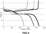
- the voltage (in volts, V) of the battery B-1 as a function of its specific capacity (in mAh / g) at a current regime of (C / 20, D / 20) and a temperature of 40 ° C is reported on the figure 3 for several cycles.
- the curve with the solid black squares represents the first cycle
- the curve with the empty black circles represents the second cycle
- the curve with the solid gray triangles represents the ninetieth cycle.
- the figure 3 shows no appearance of dendrites even after 90 cycles in battery B-1 according to the invention.
- Table 4 below presents the characteristics of the SA separator: the thickness e (in ⁇ m), the porosity P (in%), the porosity of the Gurley P Gurley type (in s / 100 cm 3 ), longitudinal thermal shrinkage measured at 100 ° C for 1 hour R L (in%), the transverse thermal shrinkage measured at 100 ° C for 1 hour R T (in%), the maximum resistance to perforation F max (in Newton N), and the elongation at break A (in mm). Unless otherwise indicated, these characteristics were obtained as described in Example 3 above.
- the positive electrode / SA separator / negative electrode assembly was then impregnated with a liquid electrolyte consisting of a 1.5 mol / l solution of LiTFSI in TEGDME.
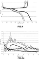
- the voltage (in volts, V) of the battery BA according to its specific capacity (in mAh / g) at a current regime of (C / 20, D / 20) and a temperature of 40 ° C is reported on the figure 4 for several cycles.
- the figure 4 shows the premature death of the BA battery at least in the ninth cycle induced by the formation of dendrites.
- the positive electrode / separator SB / negative electrode assembly was then impregnated with a liquid electrolyte consisting of a 1.5 mol / l solution of LiTFSI in TEGDME.
- Table 5 below shows the respective characteristics of separators S-2, S-3 and S-4 : the thickness e (in ⁇ m), the porosity P (in%), the porosity of type Gurley P Gurley (in s / 100 cm 3 ), the longitudinal thermal shrinkage measured at 100 ° C for 1 hour R L (in%), the transverse thermal shrinkage measured at 100 ° C for 1 hour R T (in%), the maximum resistance to the perforation F max (in Newton N), and elongation at break A (in mm). Unless otherwise indicated, these characteristics were obtained as described in Example 3 above.
- Each of the positive electrode / separator / negative electrode assemblies was then impregnated with a liquid electrolyte consisting of a 1.5 mol / l solution of LiTFSI in TEGDME.
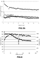
- the relative capacity corresponding to the ratio of the discharge capacity of the cycle n to the discharge capacity of the first cycle, the BA batteries (curve with open circles), B-1 (curve with solid squares), B-2 (curve with solid diamonds), B-3 (curve with empty squares) and B-4 (curve with solid squares) solid triangles) as a function of the number of cycles at a current regime of (C / 20, D / 20) and a temperature of 40 ° C is reported on the figure 5a .
- the figure 5a shows no appearance of dendrites even after 30 cycles in batteries according to the invention B-1, B-2, B-3 and B-4, regardless of the thickness of the biaxially oriented separator used. However, as observed in Comparative Example 4 above, the figure 5a shows the premature death of the BA battery not according to the invention, induced by the formation of dendrites.
- the density of energy density (ie density of capacity, considering the volume of positive electrode, separator and electrolyte) (in mAh / cm 3 ) of batteries BA (curve with the empty circles), B-1 ( curve with solid squares), B-2 (curve with solid diamonds), B-3 (curve with empty squares) and B-4 (curve with solid triangles) as a function of the number of cycles at a current regime (C / 20, D / 20) and a temperature of 40 ° C is reported on the figure 5b .
- the results of the figure 5b show the good cyclability of batteries according to the invention.
- the maximum density of energy density (117 mAh / cm 3 ) is obtained with the separator S-1 (considering the volume of positive electrode, separator and electrolyte).
- Lithium salt (LiTFSI) (28.2% by weight) was dissolved in TEGDME (21.8% by weight) with magnetic stirring at 50 ° C. Then, to the resulting mixture was added a Zeospan® POE copolymer (50% by weight). The resulting mixture was kneaded in the Plastograph® EC mixer as described in Example 2, at 80 ° C for 30 minutes. The electrolyte paste obtained was laminated at 95 ° C. between two silicone PET plastic films.
- the biaxially oriented polypropylene separator S-1 was previously impregnated with the gelled polymer electrolyte by co-rolling the separator and the gelled polymer electrolyte at 80 ° C. and at a pressure of 5 bars under a dry air atmosphere ( ie air with a dew point ⁇ -40 ° C).
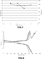
- the specific capacity (in mAh / g) during the discharge as a function of the number of cycles (curve with the solid circles), as well as the coulombic efficiency (in%), corresponding to the ratio of the discharge capacity of the cycle n on the capacity cycle charge, as a function of the number of cycles (curve with solid squares) of the battery B-5 at a current regime of D / 20 and a temperature of 40 ° C, are reported on the figure 6 .
- the figure 6 shows no appearance of dendrites even after 85 cycles in the battery according to the invention B-5.
- the volume density of energy obtained is 83 mAh / cm 3 (considering the volume of positive electrode, separator and electrolyte).
- Lithium salt (LiTFSI) (17.7% by weight) was dissolved in TEGDME (27.3% by weight) with magnetic stirring at 50 ° C. Then, to the resulting mixture was added a copolymer of Zeospan® POE (15% by weight) and a copolymer of vinylidene fluoride and hexafluoropropylene (PVdF-co-HFP) (30% by weight). The resulting mixture was kneaded in the Plastograph® EC mixer as described in Example 2 at 130 ° C for 30 minutes. The electrolyte paste obtained was laminated at 125 ° C. between two silicone PET plastic films.
- the battery does not conform to the invention because it does not include a biaxially oriented porous separator comprising at least polypropylene.
- a biaxially oriented porous separator comprising at least polypropylene.
- the specific capacity (in mAh / g) during the discharge as a function of the number of cycles (curve with the solid circles), as well as the coulombic efficiency (in%), corresponding to the ratio of the discharge capacity of the cycle n on the capacity charge of the cycle n, as a function of the number of cycles (curve with solid squares) of the battery BC at a current regime of D / 40 and a temperature of 40 ° C, are reported on the figure 7 .
- the figure 8 shows the appearance of dendrites from the third cycle in the battery not in accordance with the invention BC, resulting in an impaired cyclability visible on the figure 7 .
- This premature dendritic growth can be attributed to the degradation of the PVdF-co-HFP by the polysulfides formed during the cycling, resulting in a deterioration of the mechanical properties of the gelled polymer electrolyte which then no longer plays its role anti-dendrite.
- the volume density of energy obtained is 95 mAh / cm 3 (considering the volume of positive electrode, separator and electrolyte).
Landscapes
- Chemical & Material Sciences (AREA)
- Chemical Kinetics & Catalysis (AREA)
- Electrochemistry (AREA)
- General Chemical & Material Sciences (AREA)
- Engineering & Computer Science (AREA)
- Manufacturing & Machinery (AREA)
- Inorganic Chemistry (AREA)
- Physics & Mathematics (AREA)
- Condensed Matter Physics & Semiconductors (AREA)
- General Physics & Mathematics (AREA)
- Materials Engineering (AREA)
- Dispersion Chemistry (AREA)
- Secondary Cells (AREA)
- Cell Separators (AREA)
- Battery Electrode And Active Subsutance (AREA)
Claims (17)
- Lithium-Schwefel-Batterie, umfassend:- eine negative Elektrode, umfassend Lithiummetall oder eine Lithiummetalllegierung,- eine positive Elektrode, umfassend mindestens ein schwefelhaltiges Mittel, ausgewählt aus dem elementaren Schwefel S8 und einer schwefelhaltigen organischen Verbindung, umfassend mindestens eine S-S-Bindung, mindestens ein Polymerbindemittel P1 und mindestens ein Mittel, das eine elektronische Leitfähigkeit erzeugt,- einen Elektrolyten, umfassend mindestens einen flüssigen linearen oder cyclischen Polyether geringer molarer Masse und mindestens ein Lithiumsalz L1, und- einen porösen Separator,wobei die Lithium-Schwefel-Batterie dadurch gekennzeichnet ist, dass der poröse Separator ein biaxial ausgerichteter Separator ist, umfassend mindestens Polypropylen, und die positive Elektrode mindestens zirka 40 Ma% Schwefel (S) in Bezug zur Gesamtmasse der positiven Elektrode umfasst.
- Batterie nach Anspruch 1, dadurch gekennzeichnet, dass der Separator eine Stärke von 5 µm bis 50 µm aufweist.
- Batterie nach Anspruch 1 oder Anspruch 2, dadurch gekennzeichnet, dass der Separator eine Porosität größer oder gleich 50 Vol% aufweist.
- Batterie nach einem der vorangehenden Ansprüche, dadurch gekennzeichnet, dass der Separator Poren mit einer durchschnittlichen Größe von 50 nm bis 3 µm aufweist.
- Batterie nach einem der vorangehenden Ansprüche, dadurch gekennzeichnet, dass der Separator eine Porosität vom Typ Gurley von 50 bis 500 s/100 cm3 aufweist
- Batterie nach einem der vorangehenden Ansprüche, dadurch gekennzeichnet, dass der Separator einen Wärmeschwund in Längsrichtung und/oder einen Wärmeschwund in Querrichtung kleiner als 15 % aufweist.
- Batterie nach einem der vorangehenden Ansprüche, dadurch gekennzeichnet, dass der Polyether ausgewählt ist aus:* den Polyethylenglykolen der Formel H-[O-CH2-CH2]m-OH, wobei m zwischen 1 und 13 inklusive ist,* den Glykolethern der Formel R-[O-CH2-CH2]p-O-R', wobei p zwischen 1 und 13 inklusive ist und R und R', identisch oder unterschiedlich, lineare, verzweigte oder cyclische Alkylgruppen sind, die 1 bis 20 Kohlenstoffatome umfassen können,* den Ethern der Formel R1-[CH2-O]q-R1', wobei q zwischen 1 und 13 inklusive ist, R1 und R1', identisch oder unterschiedlich, lineare, verzweigte oder cyclische Alkyle sind, die 1 bis 20 Kohlenstoffatome und eventuell Heteroatome umfassen können,*den cyclischen Ethern, die 2 bis 20 Kohlenstoffatome umfassen können, den cyclischen Polyethern, die 3 bis 40 Kohlenstoffatome umfassen können, und* einem ihrer Gemische.
- Batterie nach einem der vorangehenden Ansprüche, dadurch gekennzeichnet, dass das Lithiumsalz L1 aus dem Lithiumfluorat (LiFO3), dem Lithium-Bis(Trifluormethansulfonyl)imid (LiTFSI), dem Lithiumhexafluorphosphat (LiPF6), dem Lithiumfluorborat (LiBF4), dem Lithiummetaborat (LiBO2), dem Lithiumperchlorat (LiClO4), dem Lithiumnitrat (LiNO3), dem Lithium-Bis(fluorsulfonyl)imid (LiFSI) und ihren Gemischen ausgewählt ist.
- Batterie nach einem der vorangehenden Ansprüche, dadurch gekennzeichnet, dass der Elektrolyt ein flüssiger Elektrolyt ist und die Konzentration des Lithiumsalzes L1 in dem flüssigen Elektrolyten 0,8 bis 8 mol/l beträgt.
- Batterie nach einem der vorangehenden Ansprüche, dadurch gekennzeichnet, dass der Elektrolyt ein gelartiger Polymerelektrolyt ist und er ferner mindestens ein Polymerbindemittel P2 umfasst.
- Batterie nach Anspruch 10, dadurch gekennzeichnet, dass der Elektrolyt 20 bis 70 Ma% Polymerbindemittel P2 umfasst.
- Batterie nach Anspruch 10 oder Anspruch 11, dadurch gekennzeichnet, dass der Elektrolyt 15 bis 45 Ma% Lithiumsalz L1 umfasst.
- Batterie nach einem der Ansprüche 10 bis 12, dadurch gekennzeichnet, dass der Elektrolyt 5 bis 40 Ma% Polyether umfasst.
- Batterie nach einem der vorangehenden Ansprüche, dadurch gekennzeichnet, dass das eine elektronische Leitfähigkeit erzeugende Mittel ein im Wesentlichen mesoporöses kohlenstoffhaltiges Mittel ist, das die folgenden Merkmale aufweist:- eine spezifische Oberfläche SBET größer oder gleich 800 m2/g, wobei die spezifische Oberfläche mit der B.E.T.-Methode berechnet wird,- eine mittlere Größe der Mesoporen zwischen 4 und 10 nm inklusive, wobei die Größe mit der B.J.H.-Methode berechnet wird, und- ein Porenvolumen insgesamt größer oder gleich 1,5 cm3/g, wobei das Porenvolumen insgesamt mit der B.E.T.-Methode berechnet wird.
- Batterie nach Anspruch 14, dadurch gekennzeichnet, dass das im Wesentlichen mesoporöse kohlenstoffhaltige Mittel in Gegenwart des schwefelhaltigen Mittels einer Vorbehandlung unterzogen wird, um ein Verbundmaterial zu bilden, das Schwefel (S) und Kohlenstoff (C) umfasst, wobei die Vorbehandlung die folgenden Schritte umfasst:i) einen Mischschritt eines kohlenstoffhaltigen, im Wesentlichen mesoporösen Mittels nach Anspruch 14 und eines schwefelhaltigen Mittels nach Anspruch 1, wobei die Schwefelmenge (S) in dem Gemisch 75 bis 85 Ma% beträgt,ii) einen Zerkleinerungsschritt des in vorangehendem Schritt i) erhaltenen Gemischs,iii) einen thermischen Behandlungsschritt des in vorangehendem Schritt ii) erhaltenen zerkleinerten Gemischs in einem verschlossenen Behälter bei einer Temperatur, die ausreichend ist, dass der Schwefel schmilzt, undiv) einen Zerkleinerungsschritt des thermisch behandelten Gemischs des vorangehenden Schritts iii), um ein Verbundmaterial zu erhalten, das Schwefel (S) und Kohlenstoff (C) umfasst.
- Batterie nach Anspruch 14 oder Anspruch 15, dadurch gekennzeichnet, dass das kohlenstoffhaltige Mittel Karbonschwarz ist.
- Herstellungsverfahren einer Batterie nach einem der Ansprüche 1 bis 16, dadurch gekennzeichnet, dass es die folgenden Schritte umfasst:A) einen Zubereitungsschritt eines flüssigen Elektrolyten oder gelartigen Polymers nach einem der Ansprüche 9 bis 13,B) einen Zusammenbauschritt einer positiven Elektrode, einer negativen Elektrode und eines Separators nach einem der Ansprüche 1 bis 16,wobei das Verfahren ferner den einen oder den anderen der folgenden Schritte umfasst:C-1) einen Imprägnierschritt des Zusammenbaus, wie in Schritt B) erhalten, mit dem flüssigen Elektrolyten, zubereitet in Schritt A), oderC-2) einen Imprägnierschritt des Separators durch den in Schritt A) zubereiteten gelartigen Polymerelektrolyten, wobei die Imprägnierung vor dem Zusammenbauschritt B) erfolgt.
Applications Claiming Priority (2)
| Application Number | Priority Date | Filing Date | Title |
|---|---|---|---|
| FR1456873A FR3023982B1 (fr) | 2014-07-17 | 2014-07-17 | Batterie lithium soufre |
| PCT/FR2015/051942 WO2016009147A1 (fr) | 2014-07-17 | 2015-07-16 | Batterie lithium soufre |
Publications (2)
| Publication Number | Publication Date |
|---|---|
| EP3170216A1 EP3170216A1 (de) | 2017-05-24 |
| EP3170216B1 true EP3170216B1 (de) | 2018-02-07 |
Family
ID=51659874
Family Applications (1)
| Application Number | Title | Priority Date | Filing Date |
|---|---|---|---|
| EP15748294.4A Active EP3170216B1 (de) | 2014-07-17 | 2015-07-16 | Lithium-schwefel-batterie |
Country Status (10)
| Country | Link |
|---|---|
| US (1) | US10109860B2 (de) |
| EP (1) | EP3170216B1 (de) |
| JP (1) | JP6473763B2 (de) |
| KR (1) | KR20170031235A (de) |
| CN (1) | CN107210409B (de) |
| CA (1) | CA2953054A1 (de) |
| ES (1) | ES2664349T3 (de) |
| FR (1) | FR3023982B1 (de) |
| SG (1) | SG11201610831PA (de) |
| WO (1) | WO2016009147A1 (de) |
Families Citing this family (14)
| Publication number | Priority date | Publication date | Assignee | Title |
|---|---|---|---|---|
| WO2018071393A1 (en) | 2016-10-11 | 2018-04-19 | Furcifer Inc. | Polymer electrolyte and electrochromic devices including polymer electrolyte |
| JP6969085B2 (ja) * | 2016-10-27 | 2021-11-24 | 日産自動車株式会社 | 非水電解質二次電池 |
| FR3059470B1 (fr) * | 2016-11-28 | 2019-05-17 | Commissariat A L'energie Atomique Et Aux Energies Alternatives | Procede de fabrication d'une electrode positive poreuse pour accumulateur electrochimique lithium-soufre |
| KR101997074B1 (ko) * | 2017-03-15 | 2019-07-08 | 한국과학기술연구원 | 폴리에틸렌이마인이 부착된 탄소재료 및 이를 코팅한 리튬-황 전지용 분리막 |
| EP3416211A1 (de) | 2017-06-14 | 2018-12-19 | Centre National De La Recherche Scientifique | Geätzte ionenspur poröse polymermembran als batterieseparator |
| FR3071360B1 (fr) * | 2017-09-18 | 2019-09-13 | Blue Solutions | Electrolyte polymere solide comprenant un polymere solvatant, un sel de lithium et un polymere halogene selectionne et batterie le comprenant |
| KR102229452B1 (ko) * | 2017-11-08 | 2021-03-17 | 주식회사 엘지화학 | 분리막 및 이를 포함하는 리튬-황 전지 |
| US10826066B2 (en) | 2018-03-23 | 2020-11-03 | Toyota Jidosha Kabushiki Kaisha | Lithium-ion secondary battery |
| WO2020226361A1 (ko) * | 2019-05-03 | 2020-11-12 | 주식회사 엘지화학 | 고체 전해질막 및 이를 제조하는 방법 및 이를 포함하는 전고체 전지 |
| US12009505B2 (en) * | 2020-05-12 | 2024-06-11 | Honeycomb Battery Company | Conducting polymer network/graphene-protected negative electrode for a lithium-ion battery |
| CN112599724B (zh) * | 2020-12-14 | 2023-03-24 | 天津市捷威动力工业有限公司 | 一种复合正极、全固态锂硫电池及它们的干法制备方法 |
| CN113193300A (zh) * | 2021-04-30 | 2021-07-30 | 湖南立方新能源科技有限责任公司 | 一种隔膜、其制备方法以及锂金属电池 |
| JP2023019106A (ja) * | 2021-07-28 | 2023-02-09 | 公立大学法人大阪 | 電極用複合粒子及びその製造方法 |
| FR3126813B1 (fr) * | 2021-09-09 | 2024-11-22 | Blue Solutions | Procédé d’extraction, de manière sécurisée, de lithium d’une batterie électrique comprenant du lithium métallique solide. |
Family Cites Families (7)
| Publication number | Priority date | Publication date | Assignee | Title |
|---|---|---|---|---|
| US5176953A (en) | 1990-12-21 | 1993-01-05 | Amoco Corporation | Oriented polymeric microporous films |
| US6030720A (en) * | 1994-11-23 | 2000-02-29 | Polyplus Battery Co., Inc. | Liquid electrolyte lithium-sulfur batteries |
| CN1412882A (zh) * | 2001-10-15 | 2003-04-23 | 三星Sdi株式会社 | 用于锂-硫电池的电解质和含有该电解质的锂-硫电池 |
| KR100467455B1 (ko) * | 2002-07-10 | 2005-01-24 | 삼성에스디아이 주식회사 | 리튬 황 전지용 양극 활물질 조성물 및 이를 사용하여 제조된 리튬 황 전지 |
| DE102009050439A1 (de) * | 2009-10-20 | 2011-05-05 | Treofan Germany Gmbh & Co. Kg | Nanoskaliges ß-Nukleierungsmittel für Polypropylen |
| FR2977722B1 (fr) * | 2011-07-05 | 2014-03-14 | Commissariat Energie Atomique | Separateur d'electrodes pour accumulateur au lithium/soufre |
| WO2013155038A1 (en) * | 2012-04-13 | 2013-10-17 | Arkema Inc. | Battery based on organosulfur species |
-
2014
- 2014-07-17 FR FR1456873A patent/FR3023982B1/fr not_active Expired - Fee Related
-
2015
- 2015-07-16 WO PCT/FR2015/051942 patent/WO2016009147A1/fr not_active Ceased
- 2015-07-16 CN CN201580039796.4A patent/CN107210409B/zh active Active
- 2015-07-16 KR KR1020177004486A patent/KR20170031235A/ko not_active Ceased
- 2015-07-16 ES ES15748294.4T patent/ES2664349T3/es active Active
- 2015-07-16 JP JP2016574438A patent/JP6473763B2/ja active Active
- 2015-07-16 EP EP15748294.4A patent/EP3170216B1/de active Active
- 2015-07-16 SG SG11201610831PA patent/SG11201610831PA/en unknown
- 2015-07-16 CA CA2953054A patent/CA2953054A1/fr not_active Abandoned
- 2015-07-16 US US15/322,714 patent/US10109860B2/en active Active
Also Published As
| Publication number | Publication date |
|---|---|
| FR3023982A1 (fr) | 2016-01-22 |
| CN107210409A (zh) | 2017-09-26 |
| CN107210409B (zh) | 2020-07-24 |
| KR20170031235A (ko) | 2017-03-20 |
| CA2953054A1 (fr) | 2016-01-21 |
| SG11201610831PA (en) | 2017-02-27 |
| FR3023982B1 (fr) | 2016-08-12 |
| US20170141397A1 (en) | 2017-05-18 |
| EP3170216A1 (de) | 2017-05-24 |
| JP6473763B2 (ja) | 2019-02-20 |
| US10109860B2 (en) | 2018-10-23 |
| JP2017526109A (ja) | 2017-09-07 |
| WO2016009147A1 (fr) | 2016-01-21 |
| ES2664349T3 (es) | 2018-04-19 |
Similar Documents
| Publication | Publication Date | Title |
|---|---|---|
| EP3170216B1 (de) | Lithium-schwefel-batterie | |
| EP3116827B1 (de) | Lithium-schwefel-batterie | |
| US11894545B2 (en) | Protected electrode structures | |
| EP3227944B1 (de) | Organische lithiumbatterie | |
| US10461333B2 (en) | Electrochemical cells comprising fibril materials | |
| CN109415394B (zh) | 用于电化学电池的组件的涂层 | |
| EP3231023B1 (de) | Organische lithiumbatterie | |
| US9728768B2 (en) | Protected electrode structures and methods | |
| CN111279526A (zh) | 用于电化学电池的保护膜 | |
| US20100266901A1 (en) | Lithium Oxygen Battery Having Enhanced Anode Environment | |
| EP3776697B1 (de) | Elektrochemisches element des lithium-schwefel-typs | |
| EP3472882B1 (de) | Verfahren zur herstellung einer als positivelektrode und als stromabnehmer wirkenden struktur für einen elektrochemischen lithium-schwefel-akkumulator | |
| HK1234530B (en) | Lithium-sulfur battery | |
| HK1234530A1 (en) | Lithium-sulfur battery |
Legal Events
| Date | Code | Title | Description |
|---|---|---|---|
| PUAI | Public reference made under article 153(3) epc to a published international application that has entered the european phase |
Free format text: ORIGINAL CODE: 0009012 |
|
| 17P | Request for examination filed |
Effective date: 20170105 |
|
| AK | Designated contracting states |
Kind code of ref document: A1 Designated state(s): AL AT BE BG CH CY CZ DE DK EE ES FI FR GB GR HR HU IE IS IT LI LT LU LV MC MK MT NL NO PL PT RO RS SE SI SK SM TR |
|
| AX | Request for extension of the european patent |
Extension state: BA ME |
|
| DAV | Request for validation of the european patent (deleted) | ||
| DAX | Request for extension of the european patent (deleted) | ||
| GRAP | Despatch of communication of intention to grant a patent |
Free format text: ORIGINAL CODE: EPIDOSNIGR1 |
|
| RIC1 | Information provided on ipc code assigned before grant |
Ipc: H01M 10/0569 20100101ALI20171026BHEP Ipc: H01M 4/62 20060101ALI20171026BHEP Ipc: H01M 4/38 20060101ALN20171026BHEP Ipc: H01M 4/58 20100101ALI20171026BHEP Ipc: H01M 10/052 20100101ALI20171026BHEP Ipc: H01M 2/16 20060101AFI20171026BHEP |
|
| INTG | Intention to grant announced |
Effective date: 20171124 |
|
| GRAS | Grant fee paid |
Free format text: ORIGINAL CODE: EPIDOSNIGR3 |
|
| GRAA | (expected) grant |
Free format text: ORIGINAL CODE: 0009210 |
|
| AK | Designated contracting states |
Kind code of ref document: B1 Designated state(s): AL AT BE BG CH CY CZ DE DK EE ES FI FR GB GR HR HU IE IS IT LI LT LU LV MC MK MT NL NO PL PT RO RS SE SI SK SM TR |
|
| REG | Reference to a national code |
Ref country code: GB Ref legal event code: FG4D Free format text: NOT ENGLISH |
|
| REG | Reference to a national code |
Ref country code: AT Ref legal event code: REF Ref document number: 969112 Country of ref document: AT Kind code of ref document: T Effective date: 20180215 Ref country code: HK Ref legal event code: DE Ref document number: 1234530 Country of ref document: HK Ref country code: CH Ref legal event code: EP |
|
| REG | Reference to a national code |
Ref country code: IE Ref legal event code: FG4D Free format text: LANGUAGE OF EP DOCUMENT: FRENCH |
|
| REG | Reference to a national code |
Ref country code: DE Ref legal event code: R096 Ref document number: 602015007955 Country of ref document: DE |
|
| REG | Reference to a national code |
Ref country code: ES Ref legal event code: FG2A Ref document number: 2664349 Country of ref document: ES Kind code of ref document: T3 Effective date: 20180419 |
|
| REG | Reference to a national code |
Ref country code: NL Ref legal event code: MP Effective date: 20180207 |
|
| REG | Reference to a national code |
Ref country code: AT Ref legal event code: MK05 Ref document number: 969112 Country of ref document: AT Kind code of ref document: T Effective date: 20180207 |
|
| REG | Reference to a national code |
Ref country code: HK Ref legal event code: GR Ref document number: 1234530 Country of ref document: HK Ref country code: FR Ref legal event code: PLFP Year of fee payment: 4 |
|
| PG25 | Lapsed in a contracting state [announced via postgrant information from national office to epo] |
Ref country code: NL Free format text: LAPSE BECAUSE OF FAILURE TO SUBMIT A TRANSLATION OF THE DESCRIPTION OR TO PAY THE FEE WITHIN THE PRESCRIBED TIME-LIMIT Effective date: 20180207 Ref country code: CY Free format text: LAPSE BECAUSE OF FAILURE TO SUBMIT A TRANSLATION OF THE DESCRIPTION OR TO PAY THE FEE WITHIN THE PRESCRIBED TIME-LIMIT Effective date: 20180207 Ref country code: HR Free format text: LAPSE BECAUSE OF FAILURE TO SUBMIT A TRANSLATION OF THE DESCRIPTION OR TO PAY THE FEE WITHIN THE PRESCRIBED TIME-LIMIT Effective date: 20180207 Ref country code: LT Free format text: LAPSE BECAUSE OF FAILURE TO SUBMIT A TRANSLATION OF THE DESCRIPTION OR TO PAY THE FEE WITHIN THE PRESCRIBED TIME-LIMIT Effective date: 20180207 Ref country code: NO Free format text: LAPSE BECAUSE OF FAILURE TO SUBMIT A TRANSLATION OF THE DESCRIPTION OR TO PAY THE FEE WITHIN THE PRESCRIBED TIME-LIMIT Effective date: 20180507 Ref country code: FI Free format text: LAPSE BECAUSE OF FAILURE TO SUBMIT A TRANSLATION OF THE DESCRIPTION OR TO PAY THE FEE WITHIN THE PRESCRIBED TIME-LIMIT Effective date: 20180207 |
|
| PG25 | Lapsed in a contracting state [announced via postgrant information from national office to epo] |
Ref country code: SE Free format text: LAPSE BECAUSE OF FAILURE TO SUBMIT A TRANSLATION OF THE DESCRIPTION OR TO PAY THE FEE WITHIN THE PRESCRIBED TIME-LIMIT Effective date: 20180207 Ref country code: LV Free format text: LAPSE BECAUSE OF FAILURE TO SUBMIT A TRANSLATION OF THE DESCRIPTION OR TO PAY THE FEE WITHIN THE PRESCRIBED TIME-LIMIT Effective date: 20180207 Ref country code: AT Free format text: LAPSE BECAUSE OF FAILURE TO SUBMIT A TRANSLATION OF THE DESCRIPTION OR TO PAY THE FEE WITHIN THE PRESCRIBED TIME-LIMIT Effective date: 20180207 Ref country code: PL Free format text: LAPSE BECAUSE OF FAILURE TO SUBMIT A TRANSLATION OF THE DESCRIPTION OR TO PAY THE FEE WITHIN THE PRESCRIBED TIME-LIMIT Effective date: 20180207 Ref country code: IS Free format text: LAPSE BECAUSE OF FAILURE TO SUBMIT A TRANSLATION OF THE DESCRIPTION OR TO PAY THE FEE WITHIN THE PRESCRIBED TIME-LIMIT Effective date: 20180607 Ref country code: BG Free format text: LAPSE BECAUSE OF FAILURE TO SUBMIT A TRANSLATION OF THE DESCRIPTION OR TO PAY THE FEE WITHIN THE PRESCRIBED TIME-LIMIT Effective date: 20180507 Ref country code: GR Free format text: LAPSE BECAUSE OF FAILURE TO SUBMIT A TRANSLATION OF THE DESCRIPTION OR TO PAY THE FEE WITHIN THE PRESCRIBED TIME-LIMIT Effective date: 20180508 Ref country code: RS Free format text: LAPSE BECAUSE OF FAILURE TO SUBMIT A TRANSLATION OF THE DESCRIPTION OR TO PAY THE FEE WITHIN THE PRESCRIBED TIME-LIMIT Effective date: 20180207 |
|
| PG25 | Lapsed in a contracting state [announced via postgrant information from national office to epo] |
Ref country code: MT Free format text: LAPSE BECAUSE OF FAILURE TO SUBMIT A TRANSLATION OF THE DESCRIPTION OR TO PAY THE FEE WITHIN THE PRESCRIBED TIME-LIMIT Effective date: 20180207 |
|
| PG25 | Lapsed in a contracting state [announced via postgrant information from national office to epo] |
Ref country code: AL Free format text: LAPSE BECAUSE OF FAILURE TO SUBMIT A TRANSLATION OF THE DESCRIPTION OR TO PAY THE FEE WITHIN THE PRESCRIBED TIME-LIMIT Effective date: 20180207 Ref country code: RO Free format text: LAPSE BECAUSE OF FAILURE TO SUBMIT A TRANSLATION OF THE DESCRIPTION OR TO PAY THE FEE WITHIN THE PRESCRIBED TIME-LIMIT Effective date: 20180207 Ref country code: EE Free format text: LAPSE BECAUSE OF FAILURE TO SUBMIT A TRANSLATION OF THE DESCRIPTION OR TO PAY THE FEE WITHIN THE PRESCRIBED TIME-LIMIT Effective date: 20180207 |
|
| REG | Reference to a national code |
Ref country code: DE Ref legal event code: R097 Ref document number: 602015007955 Country of ref document: DE |
|
| PG25 | Lapsed in a contracting state [announced via postgrant information from national office to epo] |
Ref country code: SM Free format text: LAPSE BECAUSE OF FAILURE TO SUBMIT A TRANSLATION OF THE DESCRIPTION OR TO PAY THE FEE WITHIN THE PRESCRIBED TIME-LIMIT Effective date: 20180207 Ref country code: DK Free format text: LAPSE BECAUSE OF FAILURE TO SUBMIT A TRANSLATION OF THE DESCRIPTION OR TO PAY THE FEE WITHIN THE PRESCRIBED TIME-LIMIT Effective date: 20180207 Ref country code: CZ Free format text: LAPSE BECAUSE OF FAILURE TO SUBMIT A TRANSLATION OF THE DESCRIPTION OR TO PAY THE FEE WITHIN THE PRESCRIBED TIME-LIMIT Effective date: 20180207 Ref country code: SK Free format text: LAPSE BECAUSE OF FAILURE TO SUBMIT A TRANSLATION OF THE DESCRIPTION OR TO PAY THE FEE WITHIN THE PRESCRIBED TIME-LIMIT Effective date: 20180207 |
|
| PLBE | No opposition filed within time limit |
Free format text: ORIGINAL CODE: 0009261 |
|
| STAA | Information on the status of an ep patent application or granted ep patent |
Free format text: STATUS: NO OPPOSITION FILED WITHIN TIME LIMIT |
|
| 26N | No opposition filed |
Effective date: 20181108 |
|
| PG25 | Lapsed in a contracting state [announced via postgrant information from national office to epo] |
Ref country code: LU Free format text: LAPSE BECAUSE OF NON-PAYMENT OF DUE FEES Effective date: 20180716 Ref country code: MC Free format text: LAPSE BECAUSE OF FAILURE TO SUBMIT A TRANSLATION OF THE DESCRIPTION OR TO PAY THE FEE WITHIN THE PRESCRIBED TIME-LIMIT Effective date: 20180207 |
|
| REG | Reference to a national code |
Ref country code: BE Ref legal event code: MM Effective date: 20180731 |
|
| REG | Reference to a national code |
Ref country code: IE Ref legal event code: MM4A |
|
| PG25 | Lapsed in a contracting state [announced via postgrant information from national office to epo] |
Ref country code: IE Free format text: LAPSE BECAUSE OF NON-PAYMENT OF DUE FEES Effective date: 20180716 |
|
| PG25 | Lapsed in a contracting state [announced via postgrant information from national office to epo] |
Ref country code: BE Free format text: LAPSE BECAUSE OF NON-PAYMENT OF DUE FEES Effective date: 20180731 |
|
| PGFP | Annual fee paid to national office [announced via postgrant information from national office to epo] |
Ref country code: IT Payment date: 20190730 Year of fee payment: 5 |
|
| PGFP | Annual fee paid to national office [announced via postgrant information from national office to epo] |
Ref country code: CH Payment date: 20190719 Year of fee payment: 5 |
|
| PG25 | Lapsed in a contracting state [announced via postgrant information from national office to epo] |
Ref country code: TR Free format text: LAPSE BECAUSE OF FAILURE TO SUBMIT A TRANSLATION OF THE DESCRIPTION OR TO PAY THE FEE WITHIN THE PRESCRIBED TIME-LIMIT Effective date: 20180207 |
|
| PG25 | Lapsed in a contracting state [announced via postgrant information from national office to epo] |
Ref country code: PT Free format text: LAPSE BECAUSE OF FAILURE TO SUBMIT A TRANSLATION OF THE DESCRIPTION OR TO PAY THE FEE WITHIN THE PRESCRIBED TIME-LIMIT Effective date: 20180207 |
|
| PG25 | Lapsed in a contracting state [announced via postgrant information from national office to epo] |
Ref country code: HU Free format text: LAPSE BECAUSE OF FAILURE TO SUBMIT A TRANSLATION OF THE DESCRIPTION OR TO PAY THE FEE WITHIN THE PRESCRIBED TIME-LIMIT; INVALID AB INITIO Effective date: 20150716 Ref country code: MK Free format text: LAPSE BECAUSE OF NON-PAYMENT OF DUE FEES Effective date: 20180207 |
|
| REG | Reference to a national code |
Ref country code: DE Ref legal event code: R079 Ref document number: 602015007955 Country of ref document: DE Free format text: PREVIOUS MAIN CLASS: H01M0002160000 Ipc: H01M0050409000 |
|
| PG25 | Lapsed in a contracting state [announced via postgrant information from national office to epo] |
Ref country code: SI Free format text: LAPSE BECAUSE OF NON-PAYMENT OF DUE FEES Effective date: 20180716 |
|
| REG | Reference to a national code |
Ref country code: CH Ref legal event code: PL |
|
| PG25 | Lapsed in a contracting state [announced via postgrant information from national office to epo] |
Ref country code: LI Free format text: LAPSE BECAUSE OF NON-PAYMENT OF DUE FEES Effective date: 20200731 Ref country code: CH Free format text: LAPSE BECAUSE OF NON-PAYMENT OF DUE FEES Effective date: 20200731 |
|
| PG25 | Lapsed in a contracting state [announced via postgrant information from national office to epo] |
Ref country code: IT Free format text: LAPSE BECAUSE OF NON-PAYMENT OF DUE FEES Effective date: 20200716 |
|
| REG | Reference to a national code |
Ref country code: GB Ref legal event code: 732E Free format text: REGISTERED BETWEEN 20231026 AND 20231101 |
|
| PGFP | Annual fee paid to national office [announced via postgrant information from national office to epo] |
Ref country code: GB Payment date: 20250619 Year of fee payment: 11 |
|
| REG | Reference to a national code |
Ref country code: DE Ref legal event code: R081 Ref document number: 602015007955 Country of ref document: DE Owner name: BLUE SOLUTIONS, FR Free format text: FORMER OWNERS: BLUE SOLUTIONS, ERGUE-GABERIC, FR; CENTRE NATIONAL DE LA RECHERCHE SCIENTIFIQUE, PARIS, FR; UNIVERSITE DE NANTES, NANTES, FR Ref country code: DE Ref legal event code: R081 Ref document number: 602015007955 Country of ref document: DE Owner name: CENTRE NATIONAL DE LA RECHERCHE SCIENTIFIQUE, FR Free format text: FORMER OWNERS: BLUE SOLUTIONS, ERGUE-GABERIC, FR; CENTRE NATIONAL DE LA RECHERCHE SCIENTIFIQUE, PARIS, FR; UNIVERSITE DE NANTES, NANTES, FR Ref country code: DE Ref legal event code: R081 Ref document number: 602015007955 Country of ref document: DE Owner name: NANTES UNIVERSITE, FR Free format text: FORMER OWNERS: BLUE SOLUTIONS, ERGUE-GABERIC, FR; CENTRE NATIONAL DE LA RECHERCHE SCIENTIFIQUE, PARIS, FR; UNIVERSITE DE NANTES, NANTES, FR |
|
| PGFP | Annual fee paid to national office [announced via postgrant information from national office to epo] |
Ref country code: FR Payment date: 20250620 Year of fee payment: 11 |
|
| REG | Reference to a national code |
Ref country code: ES Ref legal event code: PC2A Owner name: NANTES UNIVERSITE Effective date: 20250717 |
|
| PGFP | Annual fee paid to national office [announced via postgrant information from national office to epo] |
Ref country code: ES Payment date: 20250801 Year of fee payment: 11 |
|
| PGFP | Annual fee paid to national office [announced via postgrant information from national office to epo] |
Ref country code: DE Payment date: 20250620 Year of fee payment: 11 |