EP3171028A1 - Pompe centrifuge multicellulaire avec un piston d'équilibrage de poussée axiale dont les faces de haute et basse pression sont séparées par une garniture méchanique - Google Patents
Pompe centrifuge multicellulaire avec un piston d'équilibrage de poussée axiale dont les faces de haute et basse pression sont séparées par une garniture méchanique Download PDFInfo
- Publication number
- EP3171028A1 EP3171028A1 EP15195416.1A EP15195416A EP3171028A1 EP 3171028 A1 EP3171028 A1 EP 3171028A1 EP 15195416 A EP15195416 A EP 15195416A EP 3171028 A1 EP3171028 A1 EP 3171028A1
- Authority
- EP
- European Patent Office
- Prior art keywords
- ring
- axial
- pump housing
- centrifugal pump
- pressure
- Prior art date
- Legal status (The legal status is an assumption and is not a legal conclusion. Google has not performed a legal analysis and makes no representation as to the accuracy of the status listed.)
- Granted
Links
Images




Classifications
-
- F—MECHANICAL ENGINEERING; LIGHTING; HEATING; WEAPONS; BLASTING
- F04—POSITIVE - DISPLACEMENT MACHINES FOR LIQUIDS; PUMPS FOR LIQUIDS OR ELASTIC FLUIDS
- F04D—NON-POSITIVE-DISPLACEMENT PUMPS
- F04D29/00—Details, component parts, or accessories
- F04D29/08—Sealings
- F04D29/10—Shaft sealings
- F04D29/12—Shaft sealings using sealing-rings
- F04D29/126—Shaft sealings using sealing-rings especially adapted for liquid pumps
-
- F—MECHANICAL ENGINEERING; LIGHTING; HEATING; WEAPONS; BLASTING
- F04—POSITIVE - DISPLACEMENT MACHINES FOR LIQUIDS; PUMPS FOR LIQUIDS OR ELASTIC FLUIDS
- F04D—NON-POSITIVE-DISPLACEMENT PUMPS
- F04D1/00—Radial-flow pumps, e.g. centrifugal pumps; Helico-centrifugal pumps
- F04D1/06—Multi-stage pumps
-
- F—MECHANICAL ENGINEERING; LIGHTING; HEATING; WEAPONS; BLASTING
- F04—POSITIVE - DISPLACEMENT MACHINES FOR LIQUIDS; PUMPS FOR LIQUIDS OR ELASTIC FLUIDS
- F04D—NON-POSITIVE-DISPLACEMENT PUMPS
- F04D29/00—Details, component parts, or accessories
- F04D29/04—Shafts or bearings, or assemblies thereof
- F04D29/041—Axial thrust balancing
-
- F—MECHANICAL ENGINEERING; LIGHTING; HEATING; WEAPONS; BLASTING
- F04—POSITIVE - DISPLACEMENT MACHINES FOR LIQUIDS; PUMPS FOR LIQUIDS OR ELASTIC FLUIDS
- F04D—NON-POSITIVE-DISPLACEMENT PUMPS
- F04D29/00—Details, component parts, or accessories
- F04D29/04—Shafts or bearings, or assemblies thereof
- F04D29/041—Axial thrust balancing
- F04D29/0413—Axial thrust balancing hydrostatic; hydrodynamic thrust bearings
-
- F—MECHANICAL ENGINEERING; LIGHTING; HEATING; WEAPONS; BLASTING
- F04—POSITIVE - DISPLACEMENT MACHINES FOR LIQUIDS; PUMPS FOR LIQUIDS OR ELASTIC FLUIDS
- F04D—NON-POSITIVE-DISPLACEMENT PUMPS
- F04D29/00—Details, component parts, or accessories
- F04D29/04—Shafts or bearings, or assemblies thereof
- F04D29/041—Axial thrust balancing
- F04D29/0416—Axial thrust balancing balancing pistons
-
- F—MECHANICAL ENGINEERING; LIGHTING; HEATING; WEAPONS; BLASTING
- F04—POSITIVE - DISPLACEMENT MACHINES FOR LIQUIDS; PUMPS FOR LIQUIDS OR ELASTIC FLUIDS
- F04D—NON-POSITIVE-DISPLACEMENT PUMPS
- F04D29/00—Details, component parts, or accessories
- F04D29/04—Shafts or bearings, or assemblies thereof
- F04D29/042—Axially shiftable rotors
-
- F—MECHANICAL ENGINEERING; LIGHTING; HEATING; WEAPONS; BLASTING
- F04—POSITIVE - DISPLACEMENT MACHINES FOR LIQUIDS; PUMPS FOR LIQUIDS OR ELASTIC FLUIDS
- F04D—NON-POSITIVE-DISPLACEMENT PUMPS
- F04D29/00—Details, component parts, or accessories
- F04D29/05—Shafts or bearings, or assemblies thereof, specially adapted for elastic fluid pumps
- F04D29/051—Axial thrust balancing
-
- F—MECHANICAL ENGINEERING; LIGHTING; HEATING; WEAPONS; BLASTING
- F04—POSITIVE - DISPLACEMENT MACHINES FOR LIQUIDS; PUMPS FOR LIQUIDS OR ELASTIC FLUIDS
- F04D—NON-POSITIVE-DISPLACEMENT PUMPS
- F04D29/00—Details, component parts, or accessories
- F04D29/05—Shafts or bearings, or assemblies thereof, specially adapted for elastic fluid pumps
- F04D29/051—Axial thrust balancing
- F04D29/0513—Axial thrust balancing hydrostatic; hydrodynamic thrust bearings
-
- F—MECHANICAL ENGINEERING; LIGHTING; HEATING; WEAPONS; BLASTING
- F04—POSITIVE - DISPLACEMENT MACHINES FOR LIQUIDS; PUMPS FOR LIQUIDS OR ELASTIC FLUIDS
- F04D—NON-POSITIVE-DISPLACEMENT PUMPS
- F04D29/00—Details, component parts, or accessories
- F04D29/05—Shafts or bearings, or assemblies thereof, specially adapted for elastic fluid pumps
- F04D29/051—Axial thrust balancing
- F04D29/0516—Axial thrust balancing balancing pistons
-
- F—MECHANICAL ENGINEERING; LIGHTING; HEATING; WEAPONS; BLASTING
- F04—POSITIVE - DISPLACEMENT MACHINES FOR LIQUIDS; PUMPS FOR LIQUIDS OR ELASTIC FLUIDS
- F04D—NON-POSITIVE-DISPLACEMENT PUMPS
- F04D29/00—Details, component parts, or accessories
- F04D29/08—Sealings
- F04D29/086—Sealings especially adapted for liquid pumps
-
- F—MECHANICAL ENGINEERING; LIGHTING; HEATING; WEAPONS; BLASTING
- F04—POSITIVE - DISPLACEMENT MACHINES FOR LIQUIDS; PUMPS FOR LIQUIDS OR ELASTIC FLUIDS
- F04D—NON-POSITIVE-DISPLACEMENT PUMPS
- F04D29/00—Details, component parts, or accessories
- F04D29/08—Sealings
- F04D29/10—Shaft sealings
- F04D29/106—Shaft sealings especially adapted for liquid pumps
-
- F—MECHANICAL ENGINEERING; LIGHTING; HEATING; WEAPONS; BLASTING
- F04—POSITIVE - DISPLACEMENT MACHINES FOR LIQUIDS; PUMPS FOR LIQUIDS OR ELASTIC FLUIDS
- F04D—NON-POSITIVE-DISPLACEMENT PUMPS
- F04D29/00—Details, component parts, or accessories
- F04D29/08—Sealings
- F04D29/10—Shaft sealings
- F04D29/12—Shaft sealings using sealing-rings
-
- F—MECHANICAL ENGINEERING; LIGHTING; HEATING; WEAPONS; BLASTING
- F04—POSITIVE - DISPLACEMENT MACHINES FOR LIQUIDS; PUMPS FOR LIQUIDS OR ELASTIC FLUIDS
- F04D—NON-POSITIVE-DISPLACEMENT PUMPS
- F04D29/00—Details, component parts, or accessories
- F04D29/08—Sealings
- F04D29/10—Shaft sealings
- F04D29/12—Shaft sealings using sealing-rings
- F04D29/122—Shaft sealings using sealing-rings especially adapted for elastic fluid pumps
-
- F—MECHANICAL ENGINEERING; LIGHTING; HEATING; WEAPONS; BLASTING
- F04—POSITIVE - DISPLACEMENT MACHINES FOR LIQUIDS; PUMPS FOR LIQUIDS OR ELASTIC FLUIDS
- F04D—NON-POSITIVE-DISPLACEMENT PUMPS
- F04D29/00—Details, component parts, or accessories
- F04D29/40—Casings; Connections of working fluid
- F04D29/42—Casings; Connections of working fluid for radial or helico-centrifugal pumps
- F04D29/426—Casings; Connections of working fluid for radial or helico-centrifugal pumps especially adapted for liquid pumps
Definitions
- the invention relates to a multi-stage centrifugal pump with the features specified in the preamble of claim 1.
- the drive is often via an external motor, which is drivingly connected to a coupling with the pump shaft and on a motor chair, that is one for Recording the motor formed housing part, is picked up and attached.
- the one shaft end is sealingly guided through the pump housing and out of this, the other shaft end is mounted within the pump housing.
- the pump-side shaft end is mounted radially and / or axially within the pump housing to relieve the engine bearings.
- common to all constructions is an increased load and thus an increased wear of the motor bearings.
- the invention has the object, a generic multi-stage centrifugal pump in such a way that on the one hand, the hydraulically induced forces can be reduced to the shaft, on the other hand, however, a good, low friction and low-wear and thus long-term stable seal.
- the impellers of the pump stages are arranged directly or via a support body on a shaft which is rotatably disposed within a pump housing. At one end of this shaft for connection to a drive motor from the housing is guided sealingly out, at the other end it is disposed within the pump housing, wherein the arranged inside the pump housing shaft end is acted upon by a counter force by pressurizing a line connection to a pressure side the pump is generated, typically, but not necessarily, with the pressure of the last pump stage, ie the pressure side of the pump.
- an axial seal is provided on the shaft end mounted inside the pump housing, whose rotating part is guided on the shaft end and whose non-rotating part is axially movable within the pump housing.
- sealing means are provided according to the invention between the non-rotating axially movably mounted part and the pump housing in order to prevent there also an overflow of liquid from the pressure side to the suction side.
- Under pump housing in the context of the present invention is also an intermediate component to understand, which is incorporated into the pump housing and on which attack the sealant.
- the basic idea of the solution according to the invention is, on the one hand, to provide a hydraulic force compensation which reduces the axial forces of the pump shaft acting on the bearings, but on the other hand to provide an axial seal on the shaft end mounted inside the housing, which has only low friction and thus low wear, but which is simple in construction and reliable in the effect.
- This is achieved by providing the rotating part of the axial seal at the shaft end and the non-rotating part inside the pump housing.
- the non-rotating part of the axial seal is mounted and guided in an axially movable manner within the pump housing, wherein sealing means are provided between the axially movable mounted part of the axial seal and the pump housing.
- the entire seal is thus divided into a pure axial seal and another seal, preferably a radial seal, wherein the essential movement is intercepted in the axial seal, whereas the other, in particular radial seal must perform only small axial movements and thus by design even little wear is exposed.
- This further particular radial seal can therefore be formed inexpensively, for example, by an elastic sealing ring, whereas the axial seal can be designed by appropriately designed sealing surfaces exclusively for sealing against the rotational movement. In this case, with a suitable embodiment of the axial seal, these also absorb axial forces and thus also take the function of a thrust bearing.
- the construction according to the invention provides in a particularly advantageous manner that the sealing is not carried out by a seal between a fixed and a rotating component, but between the pump housing and the axially movable mounted and non-rotating part of the axial seal.
- This solution has the advantage that the seal has only to absorb the typically small axial movement of the non-rotating part of the axial seal, but not the friction-intensive and wear-promoting movement to the rotating part, which is received by the axial seal.
- the seal is made by the sealing gap itself, which is sufficiently small in a correspondingly dimensioned axial seal to neglect Matterströmbuche can.
- the sealants can therefore be designed cost-effective and long-term stability, without this having a noticeable effect on the efficiency of the pump.
- the solution according to the invention also has the advantage that at least to a limited extent axial forces of the shaft can be absorbed by the axial seal in the pump housing.
- the essential part of the axial forces is due to the hydraulic compensation, that is, by returning the pressure level generated by the pump generated on the free shaft end within the pump housing, so that regardless of the number of stages, the drive of the pump can be ensured with a standard motor.
- the dynamic force compensation of the hydraulically induced axial forces acting on the shaft limits the forces to be absorbed by the thrust bearing to a minimum.
- the hydraulic power compensation has the advantage that in the case of dry running, if these restoring forces do not occur, no force compensation takes place, so that even then the wear keeps within acceptable limits.
- the embodiment according to the invention has the additional advantage that, in accordance with constructive implementation, both the axial seal and the other sealing means, in particular the radial seal can be replaced without having to remove the shaft from the pump housing.
- the pump stages that is, the wheels with the associated nozzles remain in their intended position.
- the non-rotating part of the axial seal is acted upon by the pressure of the pressure side of the pump on its axial side facing away from the sealing surface, that is to say the rear side.
- the required supporting force for the axial seal or for the thrust bearing function is applied, namely dynamically, that is, depending on the output pressure of the pump.
- the non-rotating part of the axial seal has a ring whose one axial end side forms a sealing surface of the axial seal and the other thereof facing away from the rear axial side is closed and at least one recess whose pressure-effective cross-sectional area is smaller than the pressure-effective cross-sectional area of the line connection to the pressure side. It can Recess according to the present invention, an edge gap, an opening, one or more openings or the like or a combination thereof.
- the pressure-effective cross-sectional area of the one or more recesses is always smaller than the pressure-effective cross-sectional area of the one or more line connections to the pressure side, to ensure that when starting the pump, first forms a pressure in front of this closed surface of the ring, which causes the ring to move axially towards the mating face at the shaft end, and only when, after some time, the interior space defined by the ring is completely filled with liquid will this additional axial force causing the movement of the ring wears off.
- an O-ring is advantageously provided, which is held in a radially circumferential groove.
- This radially encircling groove can be provided either on the housing side or on the ring side, that is to say on the bearing side.
- this part can be made of solid material, for example as a turned part.
- this sheet metal section which covers the back of the ring and thus forms the initially pressure-effective closed axial side with the at least one recess can also be used advantageously to form the anti-rotation of the non-rotating part of the axial seal, in particular of the ring and this either rotationally fixed to the retaining ring and / or on the pump housing. Since in this respect only small forces are to be absorbed, this function can be realized by a cost-effective stamped part, which is optionally processed according to shaping.
- Shaft side is provided according to the invention to connect a retaining ring tightly and firmly with the shaft end, which is either itself formed as a sealing ring and forms an Axialdicht Structure or advantageously receives the axial sealing surface forming a sliding ring.
- a sliding ring may for example consist of highly wear-resistant silicon carbide, wherein the retaining ring may consist of a more cost-effective preferably metal material.
- the axial sealing surface forming the sliding ring is advantageously determined by means of a screwed into the retaining ring threaded bushing or a female form fit to this or with this. This allows the exchange of the axial sealing surface forming the sliding ring also without disassembly of the shaft, since the free end of the shaft is accessible from outside the pump housing and can be blocked by a tool against rotation.
- the centrifugal pump according to the invention is advantageously designed as an in-line pump, thus has a pump housing, wherein the suction port and pressure port are arranged coaxially.
- a passage between the pressure port and a space receiving the non-rotating part of the axial seal and typically located in the base of the pump housing can be easily realized. It may optionally be provided more channels to realize the required cable cross-sections.
- one of the sealing surfaces of the axial seal is designed as a three-point support, thus has distributed over the circumference three macroscopic elevations, which on the one hand ensure a defined support to the plane mating surface and on the other are particularly advantageous in terms of the structure of the lubricant film, which is when starting the Pump should build up as quickly as possible, so that the advantageous and low-wear sliding friction arises.
- the formation of this three-point support is advantageously carried out on the slide ring, since this can be processed as a separate component cost-effective with low tolerance than the other components.
- the embodiment of the invention makes it possible to provide the axial bearing of the shaft exclusively on the motor side, wherein the axial forces occurring due to the design are so small that they can be absorbed by the engine mounts without noticeably increasing their wear.
- the axial bearing of the shaft is thus advantageously carried out by one or more bearings arranged on the motor side, preferably a motor-side bearing near the pump-side end of the motor shaft.
- the ring of the non-rotating part of the axial seal be constructed in several parts and have a high wear-resistant part having the sealing surface and a carrier receiving the highly wear-resistant part, as already indicated above for the rotating part of the axial seal.
- the sliding ring and / or the highly wear-resistant part of the ring of silicon carbide or a comparable highly wear-resistant material formed which allows particularly long service life.
- a closable opening in the pump housing preferably aligned with the axial seal provided by which the axial seal can be exchanged.
- the centrifugal pump shown is a multi-stage, vertically operated centrifugal pump 1 of the inline design.
- the pump housing has a foot part 2, a head part 3 and a cylindrical shell 4 arranged therebetween, which surrounds the pump stages and is clamped between head part 3 and foot part 2.
- the foot part 2 has a suction connection 5 and in alignment with a pressure connection 6.
- the head part 3 is designed as a motor chair and surrounds a clutch 7, which has a shaft 51 of a in Fig. 1 schematically shown mounted on the head part 3 electric motor 50 rotatably connected to a shaft 8 of the pump 1 connects.
- the shaft 8 of the pump 1 carries the impellers 9 of the pump stages and is rotatably disposed within the pump housing.
- a radial seal 10 is provided in the head part 3 and in the foot part 2 an axial seal 11.
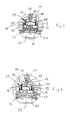
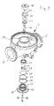
- the structure of this axial seal 11 is made of the FIGS. 3 to 8 in detail and described in detail below.
- the housing-side shaft end 15 of the pump is located in the region of the suction port 12 below the first pump stage. It has a threaded blind hole 16 in which a cap screw 17 is seated, with a retaining ring 18 is tightly and firmly attached to the shaft end 15.
- the retaining ring 18 has a directed towards the suction port 12 and, except for a central recess for performing the screw 17 closed wall 19, so is cup-shaped and tightly and firmly connected to the shaft end 15.
- the retaining ring 18 is formed as a rotating part, stepped to the side facing away from the shaft end 15 side and formed with a downwardly open circumferential groove which is provided for receiving a sliding ring 20.
- the sliding ring 20 is made of silicon carbide and is secured against rotation by means of pins 21 in the retaining ring 18 and the rest by means of a sleeve 22 which radially overlaps the sliding ring 20 on the inside and is fastened by means of the screw 7 together with the retaining ring 18 at the shaft end 15.
- the sliding ring 20 has a downwardly directed, thus facing away from the shaft end 15 axial surface 23, which forms the rotating axial surface of the axial seal 11.
- This axial surface 23 is not completely flat, but has three evenly distributed over the circumference macroscopic elevations, which on the one hand a defined contact with the counter surface 24, that is, the axial surface 24 of the non-rotating Axialdichtungsteils 25, and other serves the rapid construction of the lubricating film.
- the axial surface 24 is flat and part of the non-rotating part, here the ring 25, which is arranged axially movable within a retaining ring 26 which is incorporated in a corresponding receptacle in the bottom of the foot part 2 of the pump housing.
- the retaining ring 26 has a circumferential groove 27 on its inner side, in which an O-ring 28 is incorporated, which radially seals the ring 25 relative to the retaining ring 26 and thus with respect to the pump housing.
- the retaining ring 26 is further sealed with an outer circumferential seal 58 against the receptacle in the pump housing, as can be seen from the sectional views 4 and 7.
- the non-rotating ring 25 is covered by a sheet metal section 29 which almost completely covers this rear side of the sealing ring 25.
- the sheet metal section 29 has bent tongues 30 with which the sheet metal section is incorporated in a form-fitting manner within corresponding recesses 52 on the rear side of the ring 25. These tongues 30 protrude radially over the ring 25 and engage in these recesses 52 in the ring 25 and form part of an anti-rotation of the non-rotating ring 25.
- the sheet metal portion 29 offset by 90 ° to the tongues 30 two diametrically opposite tongues 31, which are bent from the plane of the base material by 90 ° upwards and the sheet metal portion 29 in the axial direction spaced connect with the ring 25, in which the ends 53 engage detent in a shoulder 54 on the inside of the ring 25.
- the sheet metal section 29 forms a closed surface of the underside of the ring 25 and has a central rectangular recess 32 into which engages a rectangular cross-section pin 55, the part the retaining ring 26 forms, on which the ring 25, which has the Axialdicht Structure 24, rotatably but axially movably guided.
- the pin 55 and the recess 32 are dimensioned in cross-section so that this recess 32 with the pin 55 therein together with any gap tolerances of the sheet portion 29 form a passage gap with a cross-sectional area which is significantly smaller than the cross-sectional area of channels 33 in the foot 2 of the pump housing or in the retaining ring 26 are provided and which ensure that the interior 34 of the ring 25 with the sheet metal portion 29 and the retaining ring 26 with the pressure of the pressure side of the pump, ie with the pressure at the pressure port 6, is acted upon.
- the pressure of the pressure side is also within the ring 25 and thus on the front side of the shaft 8, whereby the desired during operation certain force compensation in terms of hydraulically induced axial force of the shaft 8 takes place.
- the retaining ring 26 is part of a circular disc 56, which for incorporation in a bottom-side Maintenance opening 60 of the pump housing, here the foot part 2 is provided.
- the disc 56 is this bottom-side opening 60 closes in a shoulder 64 on the underside of the foot part 2 and is connected via four screws 57 which are guided by recesses 61 in the edge 62 of the disc 56, releasably connected to the foot part 2.
- an O-ring 58 is arranged in the upper region of the ring 26, ie at a small distance from the disk 25, which is incorporated in a circumferential radial groove of the ring 26 and for sealing this component against a recess 63 in the foot part 2 serves.
- a second O-ring 59 is incorporated in a circumferential radial groove in the lower part of the ring 26, which serves to seal against the maintenance opening 60 in the foot part 2.
- Between the O-rings 58 and 59 includes within the foot part 2, a connection to the pressure side of the centrifugal pump 1, which is fluidly connected via channels 33 in the ring 26 with the interior of the ring 26, so that above the pressure of the pressure side of the through Sheet section 29 formed initially pressure-effective surface of the non-rotating part 25 of the axial seal is present.
- the ring 26 is sealed over the O-ring 28 which lies in a groove on the inside of the retaining ring 26, opposite the ring 25, which forms the non-rotating part of the axial seal with the axial surface 24 of the seal.
- This O-ring 28 thus forms a radial seal, which, however, has to absorb only the comparatively small movements in the axial direction and is therefore subject to only slight wear.
- the shaft 8 in the field of motor chair on a cross-sectional profile, which through lateral engagement of a tool allows a locking of the shaft. It can thus, after the shaft 8 is rotatably held by means of a introduced in the field of motor chair open-end wrench, the cap screw 17 is released and after replacement of the sliding ring 20 and optionally further seals the retaining ring 18, these are screwed again.
Landscapes
- Engineering & Computer Science (AREA)
- Mechanical Engineering (AREA)
- General Engineering & Computer Science (AREA)
- Physics & Mathematics (AREA)
- Fluid Mechanics (AREA)
- Structures Of Non-Positive Displacement Pumps (AREA)
Priority Applications (4)
| Application Number | Priority Date | Filing Date | Title |
|---|---|---|---|
| ES15195416T ES2756199T3 (es) | 2015-11-19 | 2015-11-19 | Bomba centrífuga multietapa con un émbolo de compensación de empuje axial, cuyos lados de presión y de aspiración están separados por un retén frontal |
| EP15195416.1A EP3171028B1 (fr) | 2015-11-19 | 2015-11-19 | Pompe centrifuge multicellulaire avec un piston d'équilibrage de poussée axiale dont les faces de haute et basse pression sont séparées par une garniture mécanique |
| US15/355,744 US10495099B2 (en) | 2015-11-19 | 2016-11-18 | Multistage centrifugal pump with shaft hydraulic force compensation |
| CN201611027447.3A CN106870378B (zh) | 2015-11-19 | 2016-11-21 | 多级离心泵 |
Applications Claiming Priority (1)
| Application Number | Priority Date | Filing Date | Title |
|---|---|---|---|
| EP15195416.1A EP3171028B1 (fr) | 2015-11-19 | 2015-11-19 | Pompe centrifuge multicellulaire avec un piston d'équilibrage de poussée axiale dont les faces de haute et basse pression sont séparées par une garniture mécanique |
Publications (2)
| Publication Number | Publication Date |
|---|---|
| EP3171028A1 true EP3171028A1 (fr) | 2017-05-24 |
| EP3171028B1 EP3171028B1 (fr) | 2019-08-14 |
Family
ID=54608407
Family Applications (1)
| Application Number | Title | Priority Date | Filing Date |
|---|---|---|---|
| EP15195416.1A Active EP3171028B1 (fr) | 2015-11-19 | 2015-11-19 | Pompe centrifuge multicellulaire avec un piston d'équilibrage de poussée axiale dont les faces de haute et basse pression sont séparées par une garniture mécanique |
Country Status (4)
| Country | Link |
|---|---|
| US (1) | US10495099B2 (fr) |
| EP (1) | EP3171028B1 (fr) |
| CN (1) | CN106870378B (fr) |
| ES (1) | ES2756199T3 (fr) |
Citations (1)
| Publication number | Priority date | Publication date | Assignee | Title |
|---|---|---|---|---|
| NL7712699A (en) * | 1977-11-17 | 1979-05-21 | Stork Koninklijke Maschf | Centrifugal pump with thrust load counteraction - has component on shaft between high and low-pressure chambers |
Family Cites Families (9)
| Publication number | Priority date | Publication date | Assignee | Title |
|---|---|---|---|---|
| US1927543A (en) * | 1932-02-03 | 1933-09-19 | Ingersoll Rand Co | Sealing device |
| US3671138A (en) * | 1971-02-02 | 1972-06-20 | Borg Warner | Composite knockdown pump |
| JP3182307B2 (ja) * | 1994-12-27 | 2001-07-03 | 株式会社荏原製作所 | 全周流型ポンプ |
| US6309174B1 (en) * | 1997-02-28 | 2001-10-30 | Fluid Equipment Development Company, Llc | Thrust bearing for multistage centrifugal pumps |
| FR2906580B1 (fr) * | 2006-09-28 | 2009-01-09 | Snecma Sa | Pompe a moteur electrique, immergee dans le fluide a pomper |
| FR2915535B1 (fr) * | 2007-04-30 | 2009-07-24 | Snecma Sa | Machine tournante comportant un systeme d'equilibrage axial passif |
| DE102013223806A1 (de) * | 2013-11-21 | 2015-05-21 | Ksb Aktiengesellschaft | Entlastungseinrichtung |
| CN204716554U (zh) * | 2015-05-04 | 2015-10-21 | 上海东方泵业(集团)有限公司 | 一种潜水泵轴向密封结构 |
| US20170130730A1 (en) * | 2015-11-10 | 2017-05-11 | Onesubsea Ip Uk Limited | Axial bearing offloading in fluid processing machines |
-
2015
- 2015-11-19 ES ES15195416T patent/ES2756199T3/es active Active
- 2015-11-19 EP EP15195416.1A patent/EP3171028B1/fr active Active
-
2016
- 2016-11-18 US US15/355,744 patent/US10495099B2/en active Active
- 2016-11-21 CN CN201611027447.3A patent/CN106870378B/zh active Active
Patent Citations (1)
| Publication number | Priority date | Publication date | Assignee | Title |
|---|---|---|---|---|
| NL7712699A (en) * | 1977-11-17 | 1979-05-21 | Stork Koninklijke Maschf | Centrifugal pump with thrust load counteraction - has component on shaft between high and low-pressure chambers |
Also Published As
| Publication number | Publication date |
|---|---|
| ES2756199T3 (es) | 2020-04-27 |
| EP3171028B1 (fr) | 2019-08-14 |
| CN106870378B (zh) | 2019-04-23 |
| US20170146019A1 (en) | 2017-05-25 |
| CN106870378A (zh) | 2017-06-20 |
| US10495099B2 (en) | 2019-12-03 |
Similar Documents
| Publication | Publication Date | Title |
|---|---|---|
| DE4331560B4 (de) | Magnetisch gekuppelte Kreiselpumpe | |
| DE102009050359B4 (de) | Spindelmotor | |
| EP3071840B1 (fr) | Dispositif de décharge | |
| DE102008013991A1 (de) | Pumpe oder Motor | |
| EP3441619B1 (fr) | Pompe centrifuge | |
| DE102012216254A1 (de) | Außenzahnradmaschine | |
| DE102013213051A1 (de) | Fördereinrichtung zur Förderung von Öl aus einem Vorratsbehälter zu einem Getriebe eines Kraftfahrzeuges | |
| EP3199815B1 (fr) | Pompe centrifuge | |
| EP2148096B1 (fr) | Pompe centrifuge | |
| DE102010051316A1 (de) | Vakuumpumpe | |
| DE202016100479U1 (de) | Ölabscheider | |
| EP2707629B1 (fr) | Dispositif d'étanchéification d'une chambre de pompage d'une pompe à piston tournant, et pompe à piston tournant dotée de ce dispositif | |
| DE102014110583A1 (de) | Vorrichtung zum Abtrennen von Verunreinigungen aus dem Schmieröl einer Brennkraftmaschine | |
| DE102011053148A1 (de) | Radialkolbenpumpe | |
| EP3171028B1 (fr) | Pompe centrifuge multicellulaire avec un piston d'équilibrage de poussée axiale dont les faces de haute et basse pression sont séparées par une garniture mécanique | |
| DE102006055161A1 (de) | Lagerschale für eine hydrostatische Maschine und hydrostatische Maschine mit dieser Lagerschale | |
| DE102008025323B4 (de) | Kältemittelverdichter | |
| DE3303856C2 (de) | Rotationszellenpumpe | |
| EP2180976B1 (fr) | Moteur de broche | |
| EP3171033A1 (fr) | Pompe centrifuge à étages multiples avec ouverture de carter pour la maintenance d'un piston d'équilibrage de poussée axiale | |
| DE102013211647A1 (de) | Innenzahnradpumpe | |
| EP2818722B1 (fr) | Pompe centrifuge | |
| EP2233748A1 (fr) | Pompe centrifuge à plusieurs étages | |
| DE10112501A1 (de) | Hydrostatische Antriebseinheit | |
| DE3729319C2 (de) | Spiralverdichter |
Legal Events
| Date | Code | Title | Description |
|---|---|---|---|
| PUAI | Public reference made under article 153(3) epc to a published international application that has entered the european phase |
Free format text: ORIGINAL CODE: 0009012 |
|
| STAA | Information on the status of an ep patent application or granted ep patent |
Free format text: STATUS: THE APPLICATION HAS BEEN PUBLISHED |
|
| AK | Designated contracting states |
Kind code of ref document: A1 Designated state(s): AL AT BE BG CH CY CZ DE DK EE ES FI FR GB GR HR HU IE IS IT LI LT LU LV MC MK MT NL NO PL PT RO RS SE SI SK SM TR |
|
| AX | Request for extension of the european patent |
Extension state: BA ME |
|
| STAA | Information on the status of an ep patent application or granted ep patent |
Free format text: STATUS: REQUEST FOR EXAMINATION WAS MADE |
|
| 17P | Request for examination filed |
Effective date: 20171124 |
|
| RBV | Designated contracting states (corrected) |
Designated state(s): AL AT BE BG CH CY CZ DE DK EE ES FI FR GB GR HR HU IE IS IT LI LT LU LV MC MK MT NL NO PL PT RO RS SE SI SK SM TR |
|
| GRAP | Despatch of communication of intention to grant a patent |
Free format text: ORIGINAL CODE: EPIDOSNIGR1 |
|
| STAA | Information on the status of an ep patent application or granted ep patent |
Free format text: STATUS: GRANT OF PATENT IS INTENDED |
|
| INTG | Intention to grant announced |
Effective date: 20190509 |
|
| GRAS | Grant fee paid |
Free format text: ORIGINAL CODE: EPIDOSNIGR3 |
|
| GRAA | (expected) grant |
Free format text: ORIGINAL CODE: 0009210 |
|
| STAA | Information on the status of an ep patent application or granted ep patent |
Free format text: STATUS: THE PATENT HAS BEEN GRANTED |
|
| AK | Designated contracting states |
Kind code of ref document: B1 Designated state(s): AL AT BE BG CH CY CZ DE DK EE ES FI FR GB GR HR HU IE IS IT LI LT LU LV MC MK MT NL NO PL PT RO RS SE SI SK SM TR |
|
| REG | Reference to a national code |
Ref country code: GB Ref legal event code: FG4D Free format text: NOT ENGLISH |
|
| REG | Reference to a national code |
Ref country code: CH Ref legal event code: EP Ref country code: AT Ref legal event code: REF Ref document number: 1167353 Country of ref document: AT Kind code of ref document: T Effective date: 20190815 |
|
| REG | Reference to a national code |
Ref country code: IE Ref legal event code: FG4D Free format text: LANGUAGE OF EP DOCUMENT: GERMAN |
|
| REG | Reference to a national code |
Ref country code: DE Ref legal event code: R096 Ref document number: 502015009963 Country of ref document: DE |
|
| REG | Reference to a national code |
Ref country code: NL Ref legal event code: MP Effective date: 20190814 |
|
| REG | Reference to a national code |
Ref country code: LT Ref legal event code: MG4D |
|
| PG25 | Lapsed in a contracting state [announced via postgrant information from national office to epo] |
Ref country code: FI Free format text: LAPSE BECAUSE OF FAILURE TO SUBMIT A TRANSLATION OF THE DESCRIPTION OR TO PAY THE FEE WITHIN THE PRESCRIBED TIME-LIMIT Effective date: 20190814 Ref country code: LT Free format text: LAPSE BECAUSE OF FAILURE TO SUBMIT A TRANSLATION OF THE DESCRIPTION OR TO PAY THE FEE WITHIN THE PRESCRIBED TIME-LIMIT Effective date: 20190814 Ref country code: NL Free format text: LAPSE BECAUSE OF FAILURE TO SUBMIT A TRANSLATION OF THE DESCRIPTION OR TO PAY THE FEE WITHIN THE PRESCRIBED TIME-LIMIT Effective date: 20190814 Ref country code: BG Free format text: LAPSE BECAUSE OF FAILURE TO SUBMIT A TRANSLATION OF THE DESCRIPTION OR TO PAY THE FEE WITHIN THE PRESCRIBED TIME-LIMIT Effective date: 20191114 Ref country code: PT Free format text: LAPSE BECAUSE OF FAILURE TO SUBMIT A TRANSLATION OF THE DESCRIPTION OR TO PAY THE FEE WITHIN THE PRESCRIBED TIME-LIMIT Effective date: 20191216 Ref country code: NO Free format text: LAPSE BECAUSE OF FAILURE TO SUBMIT A TRANSLATION OF THE DESCRIPTION OR TO PAY THE FEE WITHIN THE PRESCRIBED TIME-LIMIT Effective date: 20191114 Ref country code: HR Free format text: LAPSE BECAUSE OF FAILURE TO SUBMIT A TRANSLATION OF THE DESCRIPTION OR TO PAY THE FEE WITHIN THE PRESCRIBED TIME-LIMIT Effective date: 20190814 Ref country code: SE Free format text: LAPSE BECAUSE OF FAILURE TO SUBMIT A TRANSLATION OF THE DESCRIPTION OR TO PAY THE FEE WITHIN THE PRESCRIBED TIME-LIMIT Effective date: 20190814 |
|
| PG25 | Lapsed in a contracting state [announced via postgrant information from national office to epo] |
Ref country code: RS Free format text: LAPSE BECAUSE OF FAILURE TO SUBMIT A TRANSLATION OF THE DESCRIPTION OR TO PAY THE FEE WITHIN THE PRESCRIBED TIME-LIMIT Effective date: 20190814 Ref country code: GR Free format text: LAPSE BECAUSE OF FAILURE TO SUBMIT A TRANSLATION OF THE DESCRIPTION OR TO PAY THE FEE WITHIN THE PRESCRIBED TIME-LIMIT Effective date: 20191115 Ref country code: IS Free format text: LAPSE BECAUSE OF FAILURE TO SUBMIT A TRANSLATION OF THE DESCRIPTION OR TO PAY THE FEE WITHIN THE PRESCRIBED TIME-LIMIT Effective date: 20191214 Ref country code: AL Free format text: LAPSE BECAUSE OF FAILURE TO SUBMIT A TRANSLATION OF THE DESCRIPTION OR TO PAY THE FEE WITHIN THE PRESCRIBED TIME-LIMIT Effective date: 20190814 Ref country code: LV Free format text: LAPSE BECAUSE OF FAILURE TO SUBMIT A TRANSLATION OF THE DESCRIPTION OR TO PAY THE FEE WITHIN THE PRESCRIBED TIME-LIMIT Effective date: 20190814 |
|
| PG25 | Lapsed in a contracting state [announced via postgrant information from national office to epo] |
Ref country code: TR Free format text: LAPSE BECAUSE OF FAILURE TO SUBMIT A TRANSLATION OF THE DESCRIPTION OR TO PAY THE FEE WITHIN THE PRESCRIBED TIME-LIMIT Effective date: 20190814 |
|
| REG | Reference to a national code |
Ref country code: ES Ref legal event code: FG2A Ref document number: 2756199 Country of ref document: ES Kind code of ref document: T3 Effective date: 20200427 |
|
| PG25 | Lapsed in a contracting state [announced via postgrant information from national office to epo] |
Ref country code: EE Free format text: LAPSE BECAUSE OF FAILURE TO SUBMIT A TRANSLATION OF THE DESCRIPTION OR TO PAY THE FEE WITHIN THE PRESCRIBED TIME-LIMIT Effective date: 20190814 Ref country code: PL Free format text: LAPSE BECAUSE OF FAILURE TO SUBMIT A TRANSLATION OF THE DESCRIPTION OR TO PAY THE FEE WITHIN THE PRESCRIBED TIME-LIMIT Effective date: 20190814 Ref country code: DK Free format text: LAPSE BECAUSE OF FAILURE TO SUBMIT A TRANSLATION OF THE DESCRIPTION OR TO PAY THE FEE WITHIN THE PRESCRIBED TIME-LIMIT Effective date: 20190814 Ref country code: RO Free format text: LAPSE BECAUSE OF FAILURE TO SUBMIT A TRANSLATION OF THE DESCRIPTION OR TO PAY THE FEE WITHIN THE PRESCRIBED TIME-LIMIT Effective date: 20190814 |
|
| PG25 | Lapsed in a contracting state [announced via postgrant information from national office to epo] |
Ref country code: SK Free format text: LAPSE BECAUSE OF FAILURE TO SUBMIT A TRANSLATION OF THE DESCRIPTION OR TO PAY THE FEE WITHIN THE PRESCRIBED TIME-LIMIT Effective date: 20190814 Ref country code: CZ Free format text: LAPSE BECAUSE OF FAILURE TO SUBMIT A TRANSLATION OF THE DESCRIPTION OR TO PAY THE FEE WITHIN THE PRESCRIBED TIME-LIMIT Effective date: 20190814 Ref country code: IS Free format text: LAPSE BECAUSE OF FAILURE TO SUBMIT A TRANSLATION OF THE DESCRIPTION OR TO PAY THE FEE WITHIN THE PRESCRIBED TIME-LIMIT Effective date: 20200224 Ref country code: SM Free format text: LAPSE BECAUSE OF FAILURE TO SUBMIT A TRANSLATION OF THE DESCRIPTION OR TO PAY THE FEE WITHIN THE PRESCRIBED TIME-LIMIT Effective date: 20190814 |
|
| REG | Reference to a national code |
Ref country code: DE Ref legal event code: R097 Ref document number: 502015009963 Country of ref document: DE |
|
| REG | Reference to a national code |
Ref country code: CH Ref legal event code: PL |
|
| PLBE | No opposition filed within time limit |
Free format text: ORIGINAL CODE: 0009261 |
|
| STAA | Information on the status of an ep patent application or granted ep patent |
Free format text: STATUS: NO OPPOSITION FILED WITHIN TIME LIMIT |
|
| PG2D | Information on lapse in contracting state deleted |
Ref country code: IS |
|
| PG25 | Lapsed in a contracting state [announced via postgrant information from national office to epo] |
Ref country code: CH Free format text: LAPSE BECAUSE OF NON-PAYMENT OF DUE FEES Effective date: 20191130 Ref country code: LI Free format text: LAPSE BECAUSE OF NON-PAYMENT OF DUE FEES Effective date: 20191130 Ref country code: LU Free format text: LAPSE BECAUSE OF NON-PAYMENT OF DUE FEES Effective date: 20191119 Ref country code: MC Free format text: LAPSE BECAUSE OF FAILURE TO SUBMIT A TRANSLATION OF THE DESCRIPTION OR TO PAY THE FEE WITHIN THE PRESCRIBED TIME-LIMIT Effective date: 20190814 |
|
| 26N | No opposition filed |
Effective date: 20200603 |
|
| REG | Reference to a national code |
Ref country code: BE Ref legal event code: MM Effective date: 20191130 |
|
| PG25 | Lapsed in a contracting state [announced via postgrant information from national office to epo] |
Ref country code: SI Free format text: LAPSE BECAUSE OF FAILURE TO SUBMIT A TRANSLATION OF THE DESCRIPTION OR TO PAY THE FEE WITHIN THE PRESCRIBED TIME-LIMIT Effective date: 20190814 |
|
| PG25 | Lapsed in a contracting state [announced via postgrant information from national office to epo] |
Ref country code: IE Free format text: LAPSE BECAUSE OF NON-PAYMENT OF DUE FEES Effective date: 20191119 |
|
| PG25 | Lapsed in a contracting state [announced via postgrant information from national office to epo] |
Ref country code: BE Free format text: LAPSE BECAUSE OF NON-PAYMENT OF DUE FEES Effective date: 20191130 |
|
| PG25 | Lapsed in a contracting state [announced via postgrant information from national office to epo] |
Ref country code: CY Free format text: LAPSE BECAUSE OF FAILURE TO SUBMIT A TRANSLATION OF THE DESCRIPTION OR TO PAY THE FEE WITHIN THE PRESCRIBED TIME-LIMIT Effective date: 20190814 |
|
| PG25 | Lapsed in a contracting state [announced via postgrant information from national office to epo] |
Ref country code: HU Free format text: LAPSE BECAUSE OF FAILURE TO SUBMIT A TRANSLATION OF THE DESCRIPTION OR TO PAY THE FEE WITHIN THE PRESCRIBED TIME-LIMIT; INVALID AB INITIO Effective date: 20151119 Ref country code: MT Free format text: LAPSE BECAUSE OF FAILURE TO SUBMIT A TRANSLATION OF THE DESCRIPTION OR TO PAY THE FEE WITHIN THE PRESCRIBED TIME-LIMIT Effective date: 20190814 |
|
| REG | Reference to a national code |
Ref country code: AT Ref legal event code: MM01 Ref document number: 1167353 Country of ref document: AT Kind code of ref document: T Effective date: 20201119 |
|
| PG25 | Lapsed in a contracting state [announced via postgrant information from national office to epo] |
Ref country code: AT Free format text: LAPSE BECAUSE OF NON-PAYMENT OF DUE FEES Effective date: 20201119 |
|
| PG25 | Lapsed in a contracting state [announced via postgrant information from national office to epo] |
Ref country code: MK Free format text: LAPSE BECAUSE OF FAILURE TO SUBMIT A TRANSLATION OF THE DESCRIPTION OR TO PAY THE FEE WITHIN THE PRESCRIBED TIME-LIMIT Effective date: 20190814 |
|
| REG | Reference to a national code |
Ref country code: DE Ref legal event code: R082 Ref document number: 502015009963 Country of ref document: DE |
|
| PGFP | Annual fee paid to national office [announced via postgrant information from national office to epo] |
Ref country code: DE Payment date: 20251119 Year of fee payment: 11 |
|
| PGFP | Annual fee paid to national office [announced via postgrant information from national office to epo] |
Ref country code: GB Payment date: 20251120 Year of fee payment: 11 |
|
| PGFP | Annual fee paid to national office [announced via postgrant information from national office to epo] |
Ref country code: IT Payment date: 20251125 Year of fee payment: 11 |
|
| PGFP | Annual fee paid to national office [announced via postgrant information from national office to epo] |
Ref country code: FR Payment date: 20251126 Year of fee payment: 11 |
|
| PGFP | Annual fee paid to national office [announced via postgrant information from national office to epo] |
Ref country code: ES Payment date: 20251229 Year of fee payment: 11 |