EP3172003B1 - Dispositif d'usinage d'une jante et procédé d'utilisation d'un dispositif d'usinage d'une jante - Google Patents
Dispositif d'usinage d'une jante et procédé d'utilisation d'un dispositif d'usinage d'une jante Download PDFInfo
- Publication number
- EP3172003B1 EP3172003B1 EP15766736.1A EP15766736A EP3172003B1 EP 3172003 B1 EP3172003 B1 EP 3172003B1 EP 15766736 A EP15766736 A EP 15766736A EP 3172003 B1 EP3172003 B1 EP 3172003B1
- Authority
- EP
- European Patent Office
- Prior art keywords
- rim
- shaped element
- milling
- funnel
- machining
- Prior art date
- Legal status (The legal status is an assumption and is not a legal conclusion. Google has not performed a legal analysis and makes no representation as to the accuracy of the status listed.)
- Active
Links
Images


Classifications
-
- B—PERFORMING OPERATIONS; TRANSPORTING
- B23—MACHINE TOOLS; METAL-WORKING NOT OTHERWISE PROVIDED FOR
- B23Q—DETAILS, COMPONENTS, OR ACCESSORIES FOR MACHINE TOOLS, e.g. ARRANGEMENTS FOR COPYING OR CONTROLLING; MACHINE TOOLS IN GENERAL CHARACTERISED BY THE CONSTRUCTION OF PARTICULAR DETAILS OR COMPONENTS; COMBINATIONS OR ASSOCIATIONS OF METAL-WORKING MACHINES, NOT DIRECTED TO A PARTICULAR RESULT
- B23Q11/00—Accessories fitted to machine tools for keeping tools or parts of the machine in good working condition or for cooling work; Safety devices specially combined with or arranged in, or specially adapted for use in connection with, machine tools
- B23Q11/0042—Devices for removing chips
-
- B—PERFORMING OPERATIONS; TRANSPORTING
- B23—MACHINE TOOLS; METAL-WORKING NOT OTHERWISE PROVIDED FOR
- B23B—TURNING; BORING
- B23B41/00—Boring or drilling machines or devices specially adapted for particular work; Accessories specially adapted therefor
-
- B—PERFORMING OPERATIONS; TRANSPORTING
- B23—MACHINE TOOLS; METAL-WORKING NOT OTHERWISE PROVIDED FOR
- B23B—TURNING; BORING
- B23B39/00—General-purpose boring or drilling machines or devices; Sets of boring and/or drilling machines
-
- B—PERFORMING OPERATIONS; TRANSPORTING
- B23—MACHINE TOOLS; METAL-WORKING NOT OTHERWISE PROVIDED FOR
- B23B—TURNING; BORING
- B23B39/00—General-purpose boring or drilling machines or devices; Sets of boring and/or drilling machines
- B23B39/003—Drilling machine situated underneath the workpiece
-
- B—PERFORMING OPERATIONS; TRANSPORTING
- B23—MACHINE TOOLS; METAL-WORKING NOT OTHERWISE PROVIDED FOR
- B23B—TURNING; BORING
- B23B47/00—Constructional features of components specially designed for boring or drilling machines; Accessories therefor
-
- B—PERFORMING OPERATIONS; TRANSPORTING
- B23—MACHINE TOOLS; METAL-WORKING NOT OTHERWISE PROVIDED FOR
- B23C—MILLING
- B23C3/00—Milling particular work; Special milling operations; Machines therefor
- B23C3/02—Milling surfaces of revolution
-
- B—PERFORMING OPERATIONS; TRANSPORTING
- B23—MACHINE TOOLS; METAL-WORKING NOT OTHERWISE PROVIDED FOR
- B23Q—DETAILS, COMPONENTS, OR ACCESSORIES FOR MACHINE TOOLS, e.g. ARRANGEMENTS FOR COPYING OR CONTROLLING; MACHINE TOOLS IN GENERAL CHARACTERISED BY THE CONSTRUCTION OF PARTICULAR DETAILS OR COMPONENTS; COMBINATIONS OR ASSOCIATIONS OF METAL-WORKING MACHINES, NOT DIRECTED TO A PARTICULAR RESULT
- B23Q3/00—Devices holding, supporting, or positioning work or tools, of a kind normally removable from the machine
- B23Q3/02—Devices holding, supporting, or positioning work or tools, of a kind normally removable from the machine for mounting on a work-table, tool-slide, or analogous part
- B23Q3/06—Work-clamping means
-
- B—PERFORMING OPERATIONS; TRANSPORTING
- B23—MACHINE TOOLS; METAL-WORKING NOT OTHERWISE PROVIDED FOR
- B23Q—DETAILS, COMPONENTS, OR ACCESSORIES FOR MACHINE TOOLS, e.g. ARRANGEMENTS FOR COPYING OR CONTROLLING; MACHINE TOOLS IN GENERAL CHARACTERISED BY THE CONSTRUCTION OF PARTICULAR DETAILS OR COMPONENTS; COMBINATIONS OR ASSOCIATIONS OF METAL-WORKING MACHINES, NOT DIRECTED TO A PARTICULAR RESULT
- B23Q37/00—Metal-working machines, or constructional combinations thereof, built-up from units designed so that at least some of the units can form parts of different machines or combinations; Units therefor in so far as the feature of interchangeability is important
-
- B—PERFORMING OPERATIONS; TRANSPORTING
- B23—MACHINE TOOLS; METAL-WORKING NOT OTHERWISE PROVIDED FOR
- B23B—TURNING; BORING
- B23B2215/00—Details of workpieces
- B23B2215/08—Automobile wheels
-
- B—PERFORMING OPERATIONS; TRANSPORTING
- B23—MACHINE TOOLS; METAL-WORKING NOT OTHERWISE PROVIDED FOR
- B23C—MILLING
- B23C2215/00—Details of workpieces
- B23C2215/08—Automotive parts
- B23C2215/085—Wheels
Definitions
- the invention relates to a device for machining a rim according to the preamble of claim 1, which is known from the document DE 30 35 505 A is known, and a method of using a device for processing a rim according to the preamble of claim 8, which is known from the document US Pat. No. 1,995,485 is known.
- Object of the present invention is to provide a simple, reliable and fast device for machining a rim while avoiding the disadvantages of the prior art.
- a device for processing a rim for a vehicle, in particular an automobile or truck comprising a means for supporting the rim, means for centering the rim, means for material processing, in particular machining, the rim with the inner side is arranged in a downward direction on the support means and is held laterally by the means for centering, in particular two means for centering, which are arranged opposite one another, wherein the rim with a central hub axis substantially concentric with respect to a machining axis of the means for support and / or a predetermined machining radius about the machining axis is to be aligned, wherein in a hub region of a direction of the inside of the rim with the means for material working out, in particular machining a material preparation, in particular the bore can be carried out by the means for circulation therethrough in the hub region, wherein the means for supporting the wheel a protective insert, in particular a funnel-shaped element, and is insertable into an inner side of the rim, wherein in particular
- the invention enables an accurate and rapid removal of possible sprue remnants in the region of the wheel hub, also called spigots or risers, in the region of a wheel hub in aluminum rims which are produced by low-pressure casting, which often contain voids and accordingly reduce the quality.
- the removal of the residues takes place in such a way that they fall down by gravity and do not remain on the rim.
- a distance in the pass is possible, without complex individual positioning of the rims.
- the invention thus eliminates a problem of chips and avoids disturbances in the chuck.
- the means for material processing, in particular machining comprises a means for drilling and / or a means for milling, in particular a milling insert, in particular with a smaller diameter than a diameter of the material processing in the rim, in particular with a means for im Essentially circular and / or helical guiding the milling insert.
- the protective insert in particular the funnel-shaped element, only has a passage to the wheel hub region, which is adapted to a material processing diameter, in particular a drill diameter and / or milling insert, in particular for a circular movement.
- the means for depressing which in particular at least one force element, in particular a power piston, comprises, in particular one or more hydraulic pistons, and / or a plate-shaped element which is to be placed from above on the rim and whereby a pressure against the Means to exercise is.
- the plate-shaped element has recesses for the means for centering.
- the rim is to be transported by a means for transporting the rim, in particular a belt comprising transport rollers, in particular driven by the means for centering, to the means for supporting the rim.
- a method according to claim 8 for use of a device for processing a rim for a vehicle, in particular an automobile, in particular according to one of claims 1 to 7, wherein the rim on a means for supporting the rim with an inside in a direction is laid down, wherein the means for supporting comprises a protective insert, in particular a funnel-shaped element, which is inserted into an inner region of the rim, the rim is inserted and held by one or more means for centering the rim in a centering position, and the rim is aligned with a central hub axis substantially concentric with respect to a machining axis of the support means and / or a predetermined machining radius, wherein in a wheel hub region from the direction of the inside of the rim with a means for material processing, in particular machining, a Material processing, in particular drilling through a means for drilling and / or a means for milling, in particular a milling insert is performed by the means for support through in the wheel hub area.
- a protective insert in particular
- a depth distance perpendicular to a circular guide can also be carried out by a means for substantially circular guiding of a milling insert, so that in particular a helical milling path is described.
- the means for material preparation for machining in the wheel hub area is to be moved, in particular approaching and / or on a movement path, in particular circular path line and / or helical track with a means for milling, to lead and / or the rim relative to the center to move to material processing is.
- the material preparation in particular machining, in particular drilling and / or milling is carried out only until a small remainder of the wheel hub region to be machined, in particular boring out towards the outside of the rim and then a separate removal of the remainder, in particular a Punching of the rest by means for punching and / or suction by means of strong negative pressure takes place.
- the rim is transported via a means for transport, on which the rim rests with the inside down, and centered by the laterally arranged means for centering to the means for support, then the protective insert, in particular the funnel-shaped element , is extended from below against the inside of the rim and a means for depressing, comprise in particular a plate-shaped element, presses from above the rim, and then with the means for material processing, in particular machining, the material removal, in particular bore through a passage the funnel-shaped element into the wheel hub region of the rim, the protective insert, in particular the funnel-shaped element, being subsequently driven back into the means for support, in which case, in particular, the machined rim after the return of the protective insert, in particular e of the funnel-shaped element, is transported on the means for transport.
- a means for depressing comprise in particular a plate-shaped element, presses from above the rim, and then with the means for material processing, in particular machining, the material removal, in particular bore through a passage the funnel-shaped element
- the protective insert in particular the funnel-shaped element, is pressed in the area of the passage substantially close to the inside of the rim, so that worked material, in particular drill chips, remain in the interior of the protective insert.
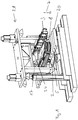
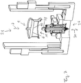
- Fig. 1 a device 21 according to the invention for processing in a perspective view.
- the device 21 is inventively provided for processing a rim 1 for a vehicle, in particular an automobile.
- a rim 1 is supplied to a means for support 2 in the center of the device 21.
- the device 21 comprises, by way of example, the means for supporting the rim 2, a means 3 for centering the rim, a means of drilling which are not visible.
- a means for depressing 17, which is placed on the rim has a plate-shaped element 18 with recesses 24 for means for centering 3.
- the means for supporting the rim 2 has a funnel-shaped element 5 and is insertable into an inner side of the rim 2, as exemplified in Fig. 4 shown.
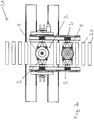
- the rim 1 is arranged with the inside in a direction 7 down on the means for support 2 and the center of the means for centering 3, in particular two means for centering 3, which are arranged opposite, held, exemplified in Fig. 2 ,
- Fig. 2 an inventive device for processing 21 in partial supervision.
- the means for transport 19 with transport rollers 20 two rims 1 are transported one after another and held centrally by the centering means 3 and in particular transported to the means for support 2.
- Means for transport 19 can also be shown at the same time cause the centering as a means of centering 3 to position the rim 1 in the middle. Once a rim is finished bored, it is packed with the means of transport via the means for centering, after it has embraced the new rim, and transported on.
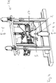
- FIG. 3 a device according to the invention for processing 21 in a perspective view.
- a plate-shaped element 18 of a means 17 for depressing with recesses 24 is lowered straight down on the rim 1, which lies on a means for support 2 and was delivered via transport rollers 20. From below, a funnel-shaped Element 5 introduced. The drill cuttings can later be collected in a drill cuttings catch 25.
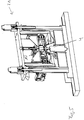
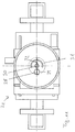
- Fig. 4 a device according to the invention for processing 21 in a sectional view.
- the rim 2 is to be aligned substantially concentrically with respect to a machining axis 9 of the means for support 2 with a central hub axis 8.
- the rim is fixed by a depressing means 17.
- a hole can be made through the funnel-shaped element 5 of the means for support 2 into the wheel hub region 10.
- Fig. 5 a device according to the invention for processing 21 in a sectional view.
- the means for drilling 4 has been drilled through to the hub portion 10.
- Fig. 6 a section of a device 2 according to the invention for editing in a sectional view.
- the funnel-shaped element 5 is arranged at least during drilling in such a way that, in the case of drilling from a direction 11 of the inner side 6 of the rim 1 with the means for drilling 4, a bore can be made through the funnel-shaped element 5 into the wheel hub region 10.
- the funnel-shaped element 5 seals against drifting out of drill cuttings 13 into an outer region 12.
- the chippings 13 fall into the inner region 14 of the rim 1.
- the funnel-shaped element 5 has only one passage 15 to the hub portion 10, which is adapted to a drill diameter 16 adapted.
- the rim 2 is substantially fixed on the funnel-shaped member 5 by means for depressing the rim 17. A remaining after drilling remainder 22 can be removed by means of subsequent punching.
- Fig. 7 shows a device 21 according to the invention for processing a rim 1 in a sectional view, wherein the means for material processing 26, in particular machining, in this case comprises a milling operation in combination with a circular movement and / or helical movement of a milling.
- the device 21 for processing a rim 1 comprises a means 26 for material processing, in particular machining, wherein the rim is held with the inner side 6 in a direction 7 downwards, wherein the rim 2 with a central hub axis 8 substantially concentric with respect to a central Axis 30 of the circular motion and / or helix movement is to be aligned, wherein in a wheel hub region 10 from a direction 11 of the inner side 6 of the rim 1 with the means for material processing 26, in particular machining a material processing, in particular a milling insert 28 by a means for support through in the rim hub portion 10 is feasible.
- Fig. 8 shows a device according to the invention 21 for editing in a sectional view, with a means for material processing 26, with a milling insert 28 in a lateral circle position, the milling insert can be performed in particular, for example, about 12,000 revolutions.
- Fig. 9 shows a device according to the invention 21 for editing in a sectional view with a means for material processing 26, with a milling insert 28 which occupies a lateral position, on a circular movement line 31.
- the device is used at different diameters 32 of the material processing in the rim.
- the smallest possible diameter is selected as the milling means in order to produce larger inner rim bores by means of circular, possibly CNC-controlled milling.
- a controlled stage, rotary table or other suitable device causes movement of the drill spindle horizontally in the X and Y axes.
- the Z-axis determines the cutting depth / drilling depth in the rim.
- the same effect of circular milling could also be generated by relative movement of the rim.
- Fig. 10 shows a device 21 according to the invention with a milling insert 28 for machining in a sectional view.
- Fig. 11 shows a device 21 according to the invention for processing in a schematic view.
Landscapes
- Engineering & Computer Science (AREA)
- Mechanical Engineering (AREA)
- Drilling And Boring (AREA)
- Turning (AREA)
Claims (13)
- Dispositif (21) pour le traitement d'une jante (1) pour un véhicule, en particulier une automobile ou un camion, un de la jante, un moyen pour le centrage (3) de la jante, un moyen (26) pour l'enlèvement de matière, en particulier usinage, dans lequel la jante avec le côté intérieur (6) est disposée dans une direction (7) vers le bas sur le moyen de déposer (2) et sur le côté du moyen pour le centrage (3), en particulier, deux moyens de centrage (3), qui sont arrangés opposés, où la jante (2) avec un axe de moyeu de roue central (8) essentiellement concentrique par rapport à un axe d'usinage (9) des moyen de déposer (2) et/ou un rayon d'usinage prédéterminé pour aligner le axe d'usinage (9), dans lequel, dans une zone de moyeu de roue (10) d'une direction (11) du côté intérieur (6) de la jante (1) avec les moyens pour l'enlèvement du matériau (26), en particulier l'usinage (4) a la préparation du matériau, en particulier l'alésage au moyen de déposer (2) est faisable jusqu'à la zone du moyeu de roue (10), caractérisé par le fait que le moyen de déposer (2) de la jante ont un insert de protection, en particulier un élément en forme d'entonnoir (5), et doit être imposé dans un côté intérieur (6) de la jante, où en particulier l'insert de protection, en particulier l'élément en forme d'entonnoir (5), au moins à la préparation des matériaux, en particulier les alésages, tels que le filet arrangé est qu'il scelle une zone extérieure (12) de la jante essentiellement contre l'extérieur-pénétrant des copeaux de préparation de matériel, en particulier les copeaux de forage (13).
- Dispositif selon la revendication 1, caractérisé par le fait que le moyen (26) pour le matériau à usiner, en particulier l'usinage, comprennent un moyen de perçage (4) et/ou un moyen de fraisage (27), en particulier un insert de fraisage (28), en particulier avec un plus petit diamètre (29) qu'un diamètre (32) de la préparation du matériau dans la jante, en particulier avec un moyen pour le plomb essentiellement circulaire et/ou hélicoïdal de l'insert de fraisage (28).
- Dispositif selon l'une des revendications 1 à 2, caractérisé en ce que l'insert de protection, en particulier l'élément en forme d'entonnoir (5), n'a qu'un seul passage (15) à la zone du moyeu de roue (10), qui est relié à un diamètre de la préparation du matériau, en particulier un diamètre de un foret (16) et/ou un insert de fraisage, en particulier pour un mouvement circulaire, est conçu adapté.
- Dispositif selon l'une des revendications 1 à 3, caractérisé en ce que la jante (2) est essentiellement fixée par un moyen de presser vers le bas (17) de la jante sur le moyen de déposer (2).
- Dispositif selon l'une des revendications 1 à 4, caractérisé en ce que le moyen de presser vers le bas (17), qui a en particulier au moins un élément de force, en particulier un piston de force, en particulier un ou plusieurs pistons hydrauliques, et/ou un élément en forme de plaque (18), qui doit être mis en place sur la jante d'en haut et exerce ainsi une pression contre le moyen de déposer (2).
- Dispositif selon l'une des revendications 1 à 5, caractérisé en ce que l'élément en forme de plaque (18) a des évidements (24) pour le centrage (3).
- Dispositif selon l'une des revendications 1 à 6, caractérisé en ce que la jante par un moyen de transport (19) de la jante, en particulier un rouleau porte-courroie (20), en particulier conduit par les moyens de centrage (3), aux moyen de déposer (2) de la jante.
- Procédure d'utilisation d'un dispositif pour le traitement (21) d'une jante (1) pour un véhicule, en particulier une automobile, en particulier selon l'une des revendications 1 à 7, dans lequel la jante (1) sur un moyen de déposer (2) de la jante avec un côté intérieur (6) est placé dans une direction (7) vers le bas, et la jante par un ou plusieurs moyens pour le centrage (3) de la jante est insérée et maintenue en position de centrage, caractérisé en ce que le moyen de déposer (2) ont un insert de protection, en particulier un élément en forme d'entonnoir (5), qui est inséré dans une zone intérieure (14) de la jante, et la jante avec un axe central de moyeu de roue (8) est essentiellement concentriques par rapport à un axe d'usinage (9) de moyen de déposer (2) et/ou à une diamètre d'usinage prédéterminée est aligné, dans lequel dans une zone de moyeu de roue (10) de la direction (11) du côté intérieur (6) de la jante avec un moyen pour le matériau à usiner (26), en particulier l'usinage (4), une préparation matérielle, en particulier alésage au moyen du perçage (4) et/ou d'un moyen de fraisage (27), en particulier un insert de fraisage (28), au moyen de déposer (2) sont effectués dans la zone du moyeu de roue (10).
- Procédure selon la revendication 8, caractérisée en ce que par le biais de la tête essentiellement circulaire d'un insert de fraisage, en particulier en plus d'un fil circulaire perpendiculaire profonde distance peut être effectuée, de sorte que, en particulier, un ligne de fraisage de form de l'hélix est décrite.
- Procédure selon la revendication 8 ou 9, caractérisé en ce que le moyen pour le matériau à usiner (26) à déplacer pour l'usinage dans la zone de moyeu de roue (10), en particulier pour être approché et/ou sur une trajectoire, en particulier la ligne circulaire (31) et/ou de ligne de l'hélix doit être transporté avec un moyen de fraisage (27), et/ou la jante (1) doit être déplacée par rapport aux moyens pour le matériau à usiner (26).
- Procédure selon l'une des revendications 8 à 10, caractérisée par le fait que la préparation matérielle, en particulier l'usinage, en particulier l'alésage et/ou le broyage, n'est effectuée que jusqu'à présent, jusqu'à ce qu'un faible résidu (22) du travail, en particulier zone de moyeu de roue de perçage (10) à l'extérieur (23) de la jante s'arrête et puis une distance séparée du reste (22), en particulier, un poinçonnage du reste au moyen d'une perforation et/ou d'une succion au moyen d'un vide s'effectue.
- Procédure selon l'une des revendications 8 à 11, caractérisé dans celui à-suivant la jante (2) par un moyen de transport (19), sur lequel la jante est placée avec le côté intérieur (6) vers le bas, et centrée par le moyen disposés latéralement pour le centrage (3) au est transporté de moyen de déposer (2), ensuite, l'insert de protection, en particulier l'élément en forme d'entonnoir (5), du fond contre l'intérieur (6) de la jante est rétracté et un moyen de presser vers le bas (17), en particulier comprend un élément en forme de plaque (18), de haut presser de la jante (2), puis avec les moyens pour l'enlèvement de matière, en particulier l'usinage (4), le levage de matériel, en particulier alésage par un passage (15) l'élément en forme d'entonnoir (18) dans la zone de moyeu de roue (10) la jante est en place, dans lequel l'insert de protection, en particulier l'élément en forme d'entonnoir (5), est repoussé dans le moyen de déposer (2), en particulier à la fermeture de la jante transformée (2) après le retour de l'insert de protection, en particulier le L'élément en forme d'entonnoir (5), sur lequel les moyens de transport (19) sont transportés plus loin.
- Procédure selon l'une des revendications 8 à 12, caractérisée en ce que l'insert de protection, en particulier l'élément en forme d'entonnoir (5), est pressé dans la zone du passage (15) essentiellement étroitement à l'intérieur (6) de la jante, de sorte que travaillé matériau, en particulier les copeaux d'alésage (13) restent à l'intérieur (14) de l'insert de protection.
Applications Claiming Priority (2)
| Application Number | Priority Date | Filing Date | Title |
|---|---|---|---|
| DE102014010877.5A DE102014010877A1 (de) | 2014-07-26 | 2014-07-26 | Vorrichtung zur Bearbeitung einer Felge und Verfahren zur Verwendung einer Vorrichtung zur Bearbeitung einer Felge |
| PCT/DE2015/000367 WO2016015700A1 (fr) | 2014-07-26 | 2015-07-23 | Dispositif d'usinage d'une jante et procédé d'utilisation d'un dispositif d'usinage de jante |
Publications (2)
| Publication Number | Publication Date |
|---|---|
| EP3172003A1 EP3172003A1 (fr) | 2017-05-31 |
| EP3172003B1 true EP3172003B1 (fr) | 2018-06-06 |
Family
ID=54150197
Family Applications (1)
| Application Number | Title | Priority Date | Filing Date |
|---|---|---|---|
| EP15766736.1A Active EP3172003B1 (fr) | 2014-07-26 | 2015-07-23 | Dispositif d'usinage d'une jante et procédé d'utilisation d'un dispositif d'usinage d'une jante |
Country Status (6)
| Country | Link |
|---|---|
| US (1) | US10870156B2 (fr) |
| EP (1) | EP3172003B1 (fr) |
| CN (1) | CN105992673B (fr) |
| DE (2) | DE102014010877A1 (fr) |
| ES (1) | ES2686709T3 (fr) |
| WO (1) | WO2016015700A1 (fr) |
Families Citing this family (16)
| Publication number | Priority date | Publication date | Assignee | Title |
|---|---|---|---|---|
| CN107414193B (zh) * | 2017-08-31 | 2023-11-17 | 中信戴卡股份有限公司 | 一种高精度去车轮轮缘毛刺装置 |
| CN108340233B (zh) * | 2018-03-20 | 2023-08-22 | 中信戴卡股份有限公司 | 一种车轮去毛刺设备 |
| CN109079542B (zh) * | 2018-08-23 | 2019-10-11 | 南京六和普什机械有限公司 | 一种高稳定性的汽车工装用夹具 |
| CN109396486B (zh) * | 2018-11-05 | 2020-04-17 | 浙江振华精锻齿轮股份有限公司 | 一种机械齿轮修补打孔辅助机构 |
| CN110681888A (zh) * | 2019-10-23 | 2020-01-14 | 中信戴卡股份有限公司 | 一种轮毂专用钻孔装置 |
| CN112296725A (zh) * | 2020-11-10 | 2021-02-02 | 江苏天宏机械工业有限公司 | 一种基于一维码识别的机加工入料定位系统 |
| CN112643089B (zh) * | 2020-11-16 | 2023-01-24 | 江苏悦达兴业汽车配件有限公司 | 一种便捷性高的汽车配件钻孔设备 |
| CN112756653A (zh) * | 2020-12-29 | 2021-05-07 | 苏州华昂智能设备制造有限公司 | 一种自动钻孔机定位装置 |
| CN112692444B (zh) * | 2021-01-22 | 2021-07-13 | 浙江铂动工贸有限公司 | 用于轮毂加工的3d激光雕刻机 |
| CN113477975B (zh) * | 2021-07-24 | 2022-06-14 | 湖北龙运汽车配件有限公司 | 一种鼓式摩擦片的钻孔设备 |
| CN113681078B (zh) * | 2021-09-02 | 2023-12-29 | 苏州市通达自动扶梯配件厂 | 一种梯级链滑动滚轮自动铰孔装置 |
| CN114309721B (zh) * | 2022-03-15 | 2022-06-07 | 江苏东方龙机车集团有限公司 | 一种汽车轮毂全自动钻孔加工设备 |
| CN115139121B (zh) * | 2022-06-18 | 2024-02-02 | 台州必拓汽车配件股份有限公司 | 发动机轴加工工装 |
| CN117139688B (zh) * | 2023-11-01 | 2024-01-02 | 常州鸿雁行机械科技有限公司 | 一种ct设备配件生产加工设备 |
| TWI904576B (zh) * | 2024-02-20 | 2025-11-11 | 雅輪實業股份有限公司 | 自動化輪圈鑽孔加工設備及方法 |
| CN117900536B (zh) * | 2024-02-27 | 2024-06-21 | 江苏圣欣不锈钢制品有限公司 | 一种工字钢连续打孔装置 |
Family Cites Families (16)
| Publication number | Priority date | Publication date | Assignee | Title |
|---|---|---|---|---|
| BE451342A (fr) * | ||||
| GB307668A (en) * | 1928-06-11 | 1929-03-14 | Ernest Reich | Improvements relating to drilling machines |
| US1995485A (en) * | 1932-07-29 | 1935-03-26 | Gen Motors Corp | Machine to countersink twenty holes in a wheel hub shell for short spokes |
| US3751053A (en) * | 1972-04-24 | 1973-08-07 | Cushman Ind Inc | Chuck with centering and compensating jaws |
| DE2302631A1 (de) * | 1973-01-17 | 1974-07-25 | Kronprinz Ag | Verfahren zum herstellen eines fahrzeugrades |
| US4490079A (en) * | 1979-03-12 | 1984-12-25 | David Trevarrow | Method of making a wheel |
| DE3035505A1 (de) * | 1979-09-21 | 1981-04-09 | Karl Böni Maschinen- und Apparatebau, Dübendorf | Koordinaten-zentrierbohrmaschine |
| DE4339755C1 (de) * | 1993-11-22 | 1995-03-09 | Chiron Werke Gmbh | Vorrichtung zum Einbringen von Bohrungen in eine Schüssel bzw. einer Felge eines Rades eines Kraftfahrzeuges |
| DE20309308U1 (de) * | 2003-06-15 | 2004-03-04 | Makra Manfred Kratzmeier Gmbh | Radaufnahme |
| ES2315654T3 (es) * | 2004-04-08 | 2009-04-01 | Maus S.P.A. | Metodo de centraje de piezas semiacabadas que deben someterse a mecanizado mecanico. |
| WO2006137089A1 (fr) * | 2005-06-22 | 2006-12-28 | Maus S.P.A. | Procédé d’usinage mécanique, en particulier pour percer et tourner des roues d’alliage léger, et installation d’usinage mécanique fonctionnant selon ledit procédé |
| DE102008014835A1 (de) * | 2008-03-07 | 2009-09-10 | Chiron-Werke Gmbh & Co Kg | Werkzeugmaschine, insbesondere für Felgenbearbeitung |
| CN202994124U (zh) * | 2012-12-17 | 2013-06-12 | 滨州盟威戴卡轮毂有限公司 | 一种轮毂中心孔检测设备 |
| JP6410023B2 (ja) * | 2013-09-06 | 2018-10-24 | パナソニックIpマネジメント株式会社 | マスタスレーブロボットの制御装置及び制御方法、ロボット、マスタスレーブロボットの制御プログラム、並びに、マスタスレーブロボットの制御用集積電子回路 |
| CN103862080A (zh) * | 2014-03-25 | 2014-06-18 | 中信戴卡股份有限公司 | 一种轮辋在线自动钻孔装置 |
| CN103862026B (zh) * | 2014-03-26 | 2015-11-25 | 中信戴卡股份有限公司 | 一种车轮毛坯在线去飞边装置 |
-
2014
- 2014-07-26 DE DE102014010877.5A patent/DE102014010877A1/de not_active Withdrawn
-
2015
- 2015-07-23 WO PCT/DE2015/000367 patent/WO2016015700A1/fr not_active Ceased
- 2015-07-23 EP EP15766736.1A patent/EP3172003B1/fr active Active
- 2015-07-23 CN CN201580002960.4A patent/CN105992673B/zh not_active Expired - Fee Related
- 2015-07-23 US US15/328,481 patent/US10870156B2/en not_active Expired - Fee Related
- 2015-07-23 DE DE112015003449.8T patent/DE112015003449A5/de not_active Withdrawn
- 2015-07-23 ES ES15766736.1T patent/ES2686709T3/es active Active
Non-Patent Citations (1)
| Title |
|---|
| None * |
Also Published As
| Publication number | Publication date |
|---|---|
| US20190143421A1 (en) | 2019-05-16 |
| CN105992673A (zh) | 2016-10-05 |
| WO2016015700A1 (fr) | 2016-02-04 |
| CN105992673B (zh) | 2020-07-28 |
| EP3172003A1 (fr) | 2017-05-31 |
| US10870156B2 (en) | 2020-12-22 |
| DE112015003449A5 (de) | 2017-04-06 |
| ES2686709T3 (es) | 2018-10-19 |
| DE102014010877A1 (de) | 2016-01-28 |
Similar Documents
| Publication | Publication Date | Title |
|---|---|---|
| EP3172003B1 (fr) | Dispositif d'usinage d'une jante et procédé d'utilisation d'un dispositif d'usinage d'une jante | |
| DE202014006593U1 (de) | Vorrichtung zur Bearbeitung einer Felge | |
| DE10002053A1 (de) | Verfahren und Vorrichtung zur Fertigung von Werkstücken, insbesondere zur Komplettfertigung komplexer Werkteile | |
| DE202009017339U1 (de) | Maschine zur Bearbeitung von gegossenen oder geschmiedeten Felgen und korrespondierendes Verfahren | |
| DE102017112416A1 (de) | Vorrichtung und Verfahren zum Anfasen eines innenverzahnten Werkstücks | |
| DE3735858A1 (de) | Vorrichtung zum einbringen von befestigungsbohrungen oder ventilbohrungen in eine schuessel bzw. eine felge eines rades eines kraftfahrzeuges | |
| EP3152000B1 (fr) | Dispositif de finition servant à la finition d'une pièce à usiner, en particulier d'un vilebrequin ou d'un arbre à cames | |
| WO2018036858A1 (fr) | Outil pour disques de frein destiné à l'usinage d'une ébauche de disque de frein, installation de fabrication de disques de frein et procédé pour fabriquer un disque de frein | |
| DE102004020723A1 (de) | Verfahren zum Spannen und anschließenden Bearbeiten eines Werkstückes sowie Vorrichtung zum Spannen eines Werkstückes zur Durchführung des Verfahrens | |
| DE102004052342A1 (de) | Verfahren zum Synchronstützschleifen und Synchronschleifmaschine | |
| DE102016115819A1 (de) | Bremsscheiben-Werkzeug zum Bearbeiten eines Bremsscheiben-Rohlings, Bremsscheiben-Herstellanlage und Verfahren zum Herstellen einer Bremsscheibe | |
| DE112012002207B4 (de) | Tragbare Werkzeugvorrichtung zum Bearbeiten eines unteren Abschnitts eines Fahrwerkgehäuses eines Luftfahrzeugs sowie Verfahren zu ihrer Anwendung | |
| AT512389B1 (de) | Werkzeugmaschine und Verfahren zur Bearbeitung eines insbesondere geschmiedeten Werkstücks | |
| DE102016118270A1 (de) | Bremsscheiben-Werkzeug zum Bearbeiten eines Bremsscheiben-Rohlings, Bremsscheiben-Herstellanlage und Verfahren zum Herstellen einer Bremsscheibe | |
| DE102009023519A1 (de) | Werkzeugmaschine | |
| DE102008046086A1 (de) | Schleifmaschine | |
| DE202011106597U1 (de) | Werkzeugmaschine, insbesondere Verzahnungs- oder Profilschleifmaschine | |
| DE102010033859B4 (de) | Verfahren zum Abstechen von Rohrstücken und Drehmaschine zur Durchführung des Verfahrens | |
| EP1412149A1 (fr) | Machine a decouper des plaquettes | |
| DE102010053405A1 (de) | Verfahren und Schleifmaschine zum Schleifen von stabförmigen Werkstücken | |
| DE102010012149A1 (de) | Verfahren und Vorrichtung zur Bearbeitung rotatorisch angetriebener Werkstücke | |
| EP1761712B1 (fr) | Procede pour realiser des pieces rotatives qui peuvent s'inserer les unes dans les autres de façon concentrique | |
| DE102004063857A1 (de) | Waferrandentfernen auf dem Werkstückaufspanntisch | |
| DE102013003771A1 (de) | Verzahnmaschine zum Bearbeiten eines Werkstücks und Vefahren zum Bearbeiten einer Kurbelwelle | |
| EP2455188B1 (fr) | Dispositif et procédé destinés à bloquer une lentille |
Legal Events
| Date | Code | Title | Description |
|---|---|---|---|
| PUAI | Public reference made under article 153(3) epc to a published international application that has entered the european phase |
Free format text: ORIGINAL CODE: 0009012 |
|
| 17P | Request for examination filed |
Effective date: 20170227 |
|
| AK | Designated contracting states |
Kind code of ref document: A1 Designated state(s): AL AT BE BG CH CY CZ DE DK EE ES FI FR GB GR HR HU IE IS IT LI LT LU LV MC MK MT NL NO PL PT RO RS SE SI SK SM TR |
|
| AX | Request for extension of the european patent |
Extension state: BA ME |
|
| RIN1 | Information on inventor provided before grant (corrected) |
Inventor name: KUNKEL, RAINER Inventor name: GROESCHL, NORMEN |
|
| DAV | Request for validation of the european patent (deleted) | ||
| DAX | Request for extension of the european patent (deleted) | ||
| GRAP | Despatch of communication of intention to grant a patent |
Free format text: ORIGINAL CODE: EPIDOSNIGR1 |
|
| INTG | Intention to grant announced |
Effective date: 20171207 |
|
| GRAS | Grant fee paid |
Free format text: ORIGINAL CODE: EPIDOSNIGR3 |
|
| GRAA | (expected) grant |
Free format text: ORIGINAL CODE: 0009210 |
|
| AK | Designated contracting states |
Kind code of ref document: B1 Designated state(s): AL AT BE BG CH CY CZ DE DK EE ES FI FR GB GR HR HU IE IS IT LI LT LU LV MC MK MT NL NO PL PT RO RS SE SI SK SM TR |
|
| REG | Reference to a national code |
Ref country code: GB Ref legal event code: FG4D Free format text: NOT ENGLISH |
|
| RIN1 | Information on inventor provided before grant (corrected) |
Inventor name: GROESCHL, NORMEN Inventor name: KUNKEL, MICHAEL |
|
| REG | Reference to a national code |
Ref country code: CH Ref legal event code: EP Ref country code: AT Ref legal event code: REF Ref document number: 1005498 Country of ref document: AT Kind code of ref document: T Effective date: 20180615 |
|
| REG | Reference to a national code |
Ref country code: IE Ref legal event code: FG4D Free format text: LANGUAGE OF EP DOCUMENT: GERMAN |
|
| REG | Reference to a national code |
Ref country code: DE Ref legal event code: R096 Ref document number: 502015004596 Country of ref document: DE |
|
| REG | Reference to a national code |
Ref country code: FR Ref legal event code: PLFP Year of fee payment: 4 |
|
| REG | Reference to a national code |
Ref country code: NL Ref legal event code: MP Effective date: 20180606 |
|
| REG | Reference to a national code |
Ref country code: ES Ref legal event code: FG2A Ref document number: 2686709 Country of ref document: ES Kind code of ref document: T3 Effective date: 20181019 |
|
| REG | Reference to a national code |
Ref country code: LT Ref legal event code: MG4D |
|
| PG25 | Lapsed in a contracting state [announced via postgrant information from national office to epo] |
Ref country code: SE Free format text: LAPSE BECAUSE OF FAILURE TO SUBMIT A TRANSLATION OF THE DESCRIPTION OR TO PAY THE FEE WITHIN THE PRESCRIBED TIME-LIMIT Effective date: 20180606 Ref country code: NO Free format text: LAPSE BECAUSE OF FAILURE TO SUBMIT A TRANSLATION OF THE DESCRIPTION OR TO PAY THE FEE WITHIN THE PRESCRIBED TIME-LIMIT Effective date: 20180906 Ref country code: FI Free format text: LAPSE BECAUSE OF FAILURE TO SUBMIT A TRANSLATION OF THE DESCRIPTION OR TO PAY THE FEE WITHIN THE PRESCRIBED TIME-LIMIT Effective date: 20180606 Ref country code: BG Free format text: LAPSE BECAUSE OF FAILURE TO SUBMIT A TRANSLATION OF THE DESCRIPTION OR TO PAY THE FEE WITHIN THE PRESCRIBED TIME-LIMIT Effective date: 20180906 Ref country code: LT Free format text: LAPSE BECAUSE OF FAILURE TO SUBMIT A TRANSLATION OF THE DESCRIPTION OR TO PAY THE FEE WITHIN THE PRESCRIBED TIME-LIMIT Effective date: 20180606 Ref country code: CY Free format text: LAPSE BECAUSE OF FAILURE TO SUBMIT A TRANSLATION OF THE DESCRIPTION OR TO PAY THE FEE WITHIN THE PRESCRIBED TIME-LIMIT Effective date: 20180606 |
|
| PG25 | Lapsed in a contracting state [announced via postgrant information from national office to epo] |
Ref country code: GR Free format text: LAPSE BECAUSE OF FAILURE TO SUBMIT A TRANSLATION OF THE DESCRIPTION OR TO PAY THE FEE WITHIN THE PRESCRIBED TIME-LIMIT Effective date: 20180907 Ref country code: HR Free format text: LAPSE BECAUSE OF FAILURE TO SUBMIT A TRANSLATION OF THE DESCRIPTION OR TO PAY THE FEE WITHIN THE PRESCRIBED TIME-LIMIT Effective date: 20180606 Ref country code: RS Free format text: LAPSE BECAUSE OF FAILURE TO SUBMIT A TRANSLATION OF THE DESCRIPTION OR TO PAY THE FEE WITHIN THE PRESCRIBED TIME-LIMIT Effective date: 20180606 Ref country code: LV Free format text: LAPSE BECAUSE OF FAILURE TO SUBMIT A TRANSLATION OF THE DESCRIPTION OR TO PAY THE FEE WITHIN THE PRESCRIBED TIME-LIMIT Effective date: 20180606 |
|
| PG25 | Lapsed in a contracting state [announced via postgrant information from national office to epo] |
Ref country code: NL Free format text: LAPSE BECAUSE OF FAILURE TO SUBMIT A TRANSLATION OF THE DESCRIPTION OR TO PAY THE FEE WITHIN THE PRESCRIBED TIME-LIMIT Effective date: 20180606 |
|
| PG25 | Lapsed in a contracting state [announced via postgrant information from national office to epo] |
Ref country code: RO Free format text: LAPSE BECAUSE OF FAILURE TO SUBMIT A TRANSLATION OF THE DESCRIPTION OR TO PAY THE FEE WITHIN THE PRESCRIBED TIME-LIMIT Effective date: 20180606 Ref country code: CZ Free format text: LAPSE BECAUSE OF FAILURE TO SUBMIT A TRANSLATION OF THE DESCRIPTION OR TO PAY THE FEE WITHIN THE PRESCRIBED TIME-LIMIT Effective date: 20180606 Ref country code: EE Free format text: LAPSE BECAUSE OF FAILURE TO SUBMIT A TRANSLATION OF THE DESCRIPTION OR TO PAY THE FEE WITHIN THE PRESCRIBED TIME-LIMIT Effective date: 20180606 Ref country code: IS Free format text: LAPSE BECAUSE OF FAILURE TO SUBMIT A TRANSLATION OF THE DESCRIPTION OR TO PAY THE FEE WITHIN THE PRESCRIBED TIME-LIMIT Effective date: 20181006 Ref country code: SK Free format text: LAPSE BECAUSE OF FAILURE TO SUBMIT A TRANSLATION OF THE DESCRIPTION OR TO PAY THE FEE WITHIN THE PRESCRIBED TIME-LIMIT Effective date: 20180606 Ref country code: PL Free format text: LAPSE BECAUSE OF FAILURE TO SUBMIT A TRANSLATION OF THE DESCRIPTION OR TO PAY THE FEE WITHIN THE PRESCRIBED TIME-LIMIT Effective date: 20180606 |
|
| PG25 | Lapsed in a contracting state [announced via postgrant information from national office to epo] |
Ref country code: SM Free format text: LAPSE BECAUSE OF FAILURE TO SUBMIT A TRANSLATION OF THE DESCRIPTION OR TO PAY THE FEE WITHIN THE PRESCRIBED TIME-LIMIT Effective date: 20180606 |
|
| REG | Reference to a national code |
Ref country code: DE Ref legal event code: R097 Ref document number: 502015004596 Country of ref document: DE |
|
| PG25 | Lapsed in a contracting state [announced via postgrant information from national office to epo] |
Ref country code: MC Free format text: LAPSE BECAUSE OF FAILURE TO SUBMIT A TRANSLATION OF THE DESCRIPTION OR TO PAY THE FEE WITHIN THE PRESCRIBED TIME-LIMIT Effective date: 20180606 Ref country code: LU Free format text: LAPSE BECAUSE OF NON-PAYMENT OF DUE FEES Effective date: 20180723 |
|
| REG | Reference to a national code |
Ref country code: BE Ref legal event code: MM Effective date: 20180731 |
|
| PLBE | No opposition filed within time limit |
Free format text: ORIGINAL CODE: 0009261 |
|
| STAA | Information on the status of an ep patent application or granted ep patent |
Free format text: STATUS: NO OPPOSITION FILED WITHIN TIME LIMIT |
|
| REG | Reference to a national code |
Ref country code: IE Ref legal event code: MM4A |
|
| PG25 | Lapsed in a contracting state [announced via postgrant information from national office to epo] |
Ref country code: IE Free format text: LAPSE BECAUSE OF NON-PAYMENT OF DUE FEES Effective date: 20180723 |
|
| 26N | No opposition filed |
Effective date: 20190307 |
|
| PG25 | Lapsed in a contracting state [announced via postgrant information from national office to epo] |
Ref country code: BE Free format text: LAPSE BECAUSE OF NON-PAYMENT OF DUE FEES Effective date: 20180731 Ref country code: DK Free format text: LAPSE BECAUSE OF FAILURE TO SUBMIT A TRANSLATION OF THE DESCRIPTION OR TO PAY THE FEE WITHIN THE PRESCRIBED TIME-LIMIT Effective date: 20180606 Ref country code: SI Free format text: LAPSE BECAUSE OF FAILURE TO SUBMIT A TRANSLATION OF THE DESCRIPTION OR TO PAY THE FEE WITHIN THE PRESCRIBED TIME-LIMIT Effective date: 20180606 |
|
| PG25 | Lapsed in a contracting state [announced via postgrant information from national office to epo] |
Ref country code: AL Free format text: LAPSE BECAUSE OF FAILURE TO SUBMIT A TRANSLATION OF THE DESCRIPTION OR TO PAY THE FEE WITHIN THE PRESCRIBED TIME-LIMIT Effective date: 20180606 |
|
| PG25 | Lapsed in a contracting state [announced via postgrant information from national office to epo] |
Ref country code: MT Free format text: LAPSE BECAUSE OF FAILURE TO SUBMIT A TRANSLATION OF THE DESCRIPTION OR TO PAY THE FEE WITHIN THE PRESCRIBED TIME-LIMIT Effective date: 20180606 |
|
| GBPC | Gb: european patent ceased through non-payment of renewal fee |
Effective date: 20190723 |
|
| PG25 | Lapsed in a contracting state [announced via postgrant information from national office to epo] |
Ref country code: TR Free format text: LAPSE BECAUSE OF FAILURE TO SUBMIT A TRANSLATION OF THE DESCRIPTION OR TO PAY THE FEE WITHIN THE PRESCRIBED TIME-LIMIT Effective date: 20180606 |
|
| PG25 | Lapsed in a contracting state [announced via postgrant information from national office to epo] |
Ref country code: GB Free format text: LAPSE BECAUSE OF NON-PAYMENT OF DUE FEES Effective date: 20190723 |
|
| PG25 | Lapsed in a contracting state [announced via postgrant information from national office to epo] |
Ref country code: PT Free format text: LAPSE BECAUSE OF FAILURE TO SUBMIT A TRANSLATION OF THE DESCRIPTION OR TO PAY THE FEE WITHIN THE PRESCRIBED TIME-LIMIT Effective date: 20180606 |
|
| PG25 | Lapsed in a contracting state [announced via postgrant information from national office to epo] |
Ref country code: MK Free format text: LAPSE BECAUSE OF NON-PAYMENT OF DUE FEES Effective date: 20180606 Ref country code: HU Free format text: LAPSE BECAUSE OF FAILURE TO SUBMIT A TRANSLATION OF THE DESCRIPTION OR TO PAY THE FEE WITHIN THE PRESCRIBED TIME-LIMIT; INVALID AB INITIO Effective date: 20150723 |
|
| P01 | Opt-out of the competence of the unified patent court (upc) registered |
Effective date: 20230521 |
|
| REG | Reference to a national code |
Ref country code: DE Ref legal event code: R409 Ref document number: 502015004596 Country of ref document: DE Ref country code: DE Ref legal event code: R119 Ref document number: 502015004596 Country of ref document: DE |
|
| PGFP | Annual fee paid to national office [announced via postgrant information from national office to epo] |
Ref country code: ES Payment date: 20250826 Year of fee payment: 11 |
|
| PGFP | Annual fee paid to national office [announced via postgrant information from national office to epo] |
Ref country code: DE Payment date: 20250813 Year of fee payment: 11 |
|
| PGFP | Annual fee paid to national office [announced via postgrant information from national office to epo] |
Ref country code: IT Payment date: 20250730 Year of fee payment: 11 |
|
| PGFP | Annual fee paid to national office [announced via postgrant information from national office to epo] |
Ref country code: FR Payment date: 20250730 Year of fee payment: 11 Ref country code: AT Payment date: 20250731 Year of fee payment: 11 |
|
| PGFP | Annual fee paid to national office [announced via postgrant information from national office to epo] |
Ref country code: CH Payment date: 20250813 Year of fee payment: 11 |