EP3176606A2 - Procédé destiné à l'alignement d'un scanner laser - Google Patents
Procédé destiné à l'alignement d'un scanner laser Download PDFInfo
- Publication number
- EP3176606A2 EP3176606A2 EP16194669.4A EP16194669A EP3176606A2 EP 3176606 A2 EP3176606 A2 EP 3176606A2 EP 16194669 A EP16194669 A EP 16194669A EP 3176606 A2 EP3176606 A2 EP 3176606A2
- Authority
- EP
- European Patent Office
- Prior art keywords
- laser scanner
- markings
- orientation
- reference object
- reference line
- Prior art date
- Legal status (The legal status is an assumption and is not a legal conclusion. Google has not performed a legal analysis and makes no representation as to the accuracy of the status listed.)
- Granted
Links
Images


Classifications
-
- G—PHYSICS
- G01—MEASURING; TESTING
- G01S—RADIO DIRECTION-FINDING; RADIO NAVIGATION; DETERMINING DISTANCE OR VELOCITY BY USE OF RADIO WAVES; LOCATING OR PRESENCE-DETECTING BY USE OF THE REFLECTION OR RERADIATION OF RADIO WAVES; ANALOGOUS ARRANGEMENTS USING OTHER WAVES
- G01S17/00—Systems using the reflection or reradiation of electromagnetic waves other than radio waves, e.g. lidar systems
- G01S17/02—Systems using the reflection of electromagnetic waves other than radio waves
- G01S17/06—Systems determining position data of a target
- G01S17/42—Simultaneous measurement of distance and other co-ordinates
-
- G—PHYSICS
- G01—MEASURING; TESTING
- G01S—RADIO DIRECTION-FINDING; RADIO NAVIGATION; DETERMINING DISTANCE OR VELOCITY BY USE OF RADIO WAVES; LOCATING OR PRESENCE-DETECTING BY USE OF THE REFLECTION OR RERADIATION OF RADIO WAVES; ANALOGOUS ARRANGEMENTS USING OTHER WAVES
- G01S7/00—Details of systems according to groups G01S13/00, G01S15/00, G01S17/00
- G01S7/48—Details of systems according to groups G01S13/00, G01S15/00, G01S17/00 of systems according to group G01S17/00
- G01S7/497—Means for monitoring or calibrating
- G01S7/4972—Alignment of sensor
Definitions
- the present invention relates to a method for aligning a laser scanner whose alignment is variable by means of an adjusting device at least about a pitch axis and a roll axis.
- a laser beam is deflected by means of a scanning device usually cyclically into different solid angles.
- the reflected or remitted by scanned objects light is detected by suitable sensors.
- scanning devices for example rotating mirrors or prisms are used.
- the light used by laser scanners can be in the visible or invisible wavelength range (ultraviolet or infrared range).
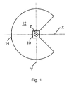
- the scanning axis ie the axis about which the laser beam rotates forms the z-axis, which is also referred to as the vertical axis or yaw axis.
- the axis dividing the sector-shaped scan area in the middle is defined as the x-axis.
- the x-axis corresponds so to speak, the "direction of view" of the laser scanner and is also referred to as roll axis.
- the y-axis is perpendicular to the x- and z-axis and is also called the pitch axis.
- the alignment with respect to the vertical axis is generally not critical and can be carried out, for example, by means of markings provided on the laser scanner or by electronic determination of the scan area
- the alignment of the laser scanner with respect to the pitch and roll axis is more complex.
- alignment of the laser scanner by means of a spirit level is known.
- the achievable accuracy is often insufficient.
- a sufficiently large, flat reference surface must be present on the laser scanner, which entails restrictions in the design and size.
- only a horizontal orientation is possible by means of a spirit level, unless other aids (wedges or the like) are taken to the rescue.
- a time-of-flight measurement of the distance of defined shaped and positioned solids is performed, the volume being shaped and arranged such that the measurement gives an extreme runtime value when the desired pitch angle is present.
- DE 102 17 295 A1 describes the alignment of a laser scanner mounted on a motor vehicle, in which the vehicle is moved along a test track and the scanning line is detected along a test surface by detecting means provided there for detecting the scanning plane of the scanner.
- DE 101 22 664 A1 describes the calibration of a laser scanner mounted on a vehicle using different objects detectable by the scanner, which are placed around the vehicle and allow calibration in the xy plane.
- two superimposed detectors are used, which detect the laser beam depending on the orientation of the scanning plane.
- An essential component of the reference object are the markings, which are provided, for example, by reflective and / or remitting materials, e.g. Adhesive strips arranged on a suitable support or substrate.
- the markings may be applied to a plate, a cardboard sheet or the like placed within the scanning area.
- the type of contrast is basically irrelevant to the method according to the invention. Even if it is subsequently assumed that marks reflect the light more strongly than the surrounding area, it is also possible to use markings which provide an inverse contrast, e.g. black markings on a white wall.
- the markings have to run transversely to the reference line for proper implementation of the method, although a right angle between the markers and the reference line for the sake of simple evaluation is particularly advantageous, but not mandatory. Deviations from the perpendicular of a few degrees, e.g. up to about 10 ° to 20 °, can be tolerated with appropriate consideration in the evaluation.
- the detection of whether there is a deviation or a match between the determined and the desired orientation can, for example, take place by means of a comparison between the acquired scanning pattern and a reference pattern, wherein the orientation of the laser scanner corresponds to a desired orientation if the detected scanning pattern corresponds to the reference pattern.
- a correspondence between the generated scanning pattern and the reference pattern is in this sense not only if the two patterns are identical, but also if the patterns are geometrically similar to each other, for example, if the ratios of the distances between different marks in the scanning correspond to the corresponding ratios in the reference pattern. This makes it possible to use the inventive method even with different distances between the laser scanner and the reference object.
- the detection of whether there is a deviation or a correspondence between the determined and the desired orientation can also be made on the basis of information present within the scanning pattern, e.g. by means of a comparison of various detected markings with respect to certain features, which comprise, for example, geometric characteristics or brightness differences.
- the term "detected marking” is understood here to mean a structure in the scanning pattern which represents the associated marking.
- the desired orientation of the laser scanner is essentially determined by the position and orientation of the reference object.
- the actual alignment of the laser scanner may then be done manually, for example, by outputting user instructions based on the scan pattern and by using the adjustment device to make the corresponding changes in orientation.
- the user instructions may consist in that the sampling pattern by means of a suitable Display device is displayed so that the user recognizes the necessary adjustment.
- an adjusting device for an automatic adjustment can be provided, which is connected to an evaluation unit, which determines due to an evaluation of the scanning possibly required adjustment movements and transmitted to the adjusting device, which are carried out by this.
- the method according to the invention is not limited to laser scanners in which the scanning beam moves in a plane, e.g. in so-called Einlagenscannern, but can also in other embodiments, in which the scanning beam, for example. moved on a conical surface, or used in multi-layer scanners. Since, in a non-planar scan area, spacing-dependent distortions of the scan line may occur, i. the scan line does not extend in a plane, it is advisable to operate if necessary, a multi-layer scanner so that the scanning beam moves during alignment in a plane.
- the shape and / or the arrangement of the markings are chosen such that it is detected on the basis of the shape of the scanning pattern, whether the orientation of the laser scanner with respect to the pitch axis and / or with respect to the roll axis deviates from the desired orientation, wherein the Alignment of the laser scanner is changed by the axis for which a deviation has been detected, so that this deviation is reduced or eliminated.
- a deviation of the pitch angle from a desired pitch angle and a deviation of the roll angle from a desired roll angle can be differentiated. This allows a targeted removal of any existing deviation of the orientation of the laser scanner from a desired orientation.
- the direction of this deviation is recognized and taken into account in particular when changing the orientation of the alignment of the laser scanner.
- the direction of the deviation is understood to mean whether the pitch or roll angle differs by a positive or negative amount from the desired pitch or roll angle.
- the direction and / or the amount of a possible deviation can be obtained not only from a comparison of the scanning pattern with a reference pattern, but advantageously also from information contained in the scanning pattern itself. This will be discussed in more detail below.
- the scanning of the reference object and the changing of the orientation of the laser scanner are carried out iteratively, wherein in particular an increment with which the orientation is changed is reduced with each iteration.
- an increment with which the orientation is changed is reduced with each iteration.
- the shape and / or the arrangement of the markings is selected such that on the basis of the number of detected markings and / or on the basis of at least one predetermined characteristic of at least one of the detected markings it can be determined whether the orientation of the laser scanner of the desired orientation deviates, with the given Criterion comprises the width of the detected mark in the direction of the reference line or in the scanning direction and / or the signal level of the detected mark.
- all or part of the markings may have a width varying over their length, so that, depending on where the mark is swept by the scanning beam, the width of the detected mark varies and thus as a criterion, in particular when determining the amount an existing deviation of the orientation can be used.
- the signal height of the detected marking in the scanning pattern can also be used, since in this case an integration of the light intensity over the width of the detected marking takes place in principle, and thus an approximately linear relationship between the signal height and the width of the detected mark.
- a deviation of the alignment based on a comparison of the widths or signal heights of two or more detected markings can be determined without reference to a reference pattern, which corresponds to the above-mentioned evaluation of information contained in the scanning itself.
- one part of the markings is assigned to an inner area of the reference object and another part of the markings is assigned to a two-part outer area of the reference object, the two parts of the outer area being arranged in the direction of the reference line on both sides of the inner area, wherein a first Level of alignment are taken into account only the markers associated with the interior, and in a subsequent second stage of alignment exclusively or additionally, the markers associated with the outside area are taken into account.
- the markings provided in the two parts of the outside area have a greater distance from the center of the reference object than the marks provided in the interior.
- the accuracy of alignment that can be achieved with the method according to the invention is in fact u.a. determined by the distance of the markings from each other in the direction of the reference line. The greater the distance between the markers, the more accurate alignment can be.
- the method is carried out in two or more stages, initially using markings which are located close to one another, so that a correct sweep of the markings by the scanning beam is ensured even in the case of a large misalignment of the laser scanner.
- a more precise alignment can be carried out on the basis of the further outward markings in the following stage (s).
- the reference object may be formed in one piece and comprise both the inner area and the two outer areas. Alternatively, it is also possible to design the reference object in multiple pieces, wherein each one section is provided for the interior and each outdoor area.
- the invention also relates to a flat reference object for aligning a laser scanner, which is designed in particular for carrying out the method described above, with a plurality of strip-like detectable by the laser scanner markers which extend transversely to a reference line and spaced from each other in the direction of the reference line, wherein a Part of the markers of a first group and another part of the markers are assigned in a second group, and wherein the markers associated with the first group with respect to the reference line and with respect to a perpendicular to the reference line symmetry line on the one side and the second group associated markers are arranged with respect to the reference line and with respect to the symmetry line on the other side.
- Each group has one or more markings.
- the area of the reference object is thus subdivided by the reference line and by the symmetry line into a matrix with 2 ⁇ 2 fields, the two groups of markings being arranged in two diagonally opposite fields. In the other two, also diagonally opposite fields need no marks are provided, but this is not excluded. If the orientation of the laser scanner matches the desired orientation defined by the reference object, the scanning beam will sweep the reference line. With such a reference object, it is possible to detect on the one hand whether there is a deviation with respect to the roll or pitch angle, and on the other hand also to determine the direction of such a deviation, so that on the basis of the scanning pattern a correction of the alignment about a specific axis and can be arranged in a certain direction.
- the first group and the second group of markings with respect to the shape and / or the position of the respective markings are point-symmetrical with respect to the point of intersection between the reference line and the symmetry line.
- one of the markers is designed as a center mark, which extends along the symmetry line on both sides of the reference line. This makes it possible to find the reference object reliably and, in particular, also makes it possible to distinguish whether the reference object was not scanned at all or whether there is a certain deviation with respect to the roll angle at which none of the markings associated with the two aforementioned groups was detected. Without existing center mark both scanning patterns would have no detected markers, while in the latter case with existing center mark this is usually detected.
- At least some of the markings have a constant width.
- at least one other part of the markings has a wedge-shaped form, wherein in particular its width increases with increasing distance from the reference line.
- the width here refers to the extent of the markings in the direction of the reference line. Basically, a sufficiently rapid and precise alignment of the laser scanner is possible even when using markers with a constant width.
- wedge-shaped markings at least some quantification of the deviation from the desired orientation can be made.
- each group of markers has at least one first mark whose end facing the reference line touches the reference lines, and at least one second mark whose end facing the reference line is spaced from the reference line.
- the lengths of the first and second markers are chosen so that the markers are just barely and the second markers are no longer detected when the orientation of the laser scanner corresponds to the desired orientation, i. when the scanning beam of the laser scanner sweeps over the reference line.
- the present invention further relates to a laser scanner arrangement, which is designed in particular for carrying out the method described above, with a laser scanner, an adjusting device which is designed to change the orientation of the laser scanner at least about a pitch axis and a roll axis, a reference object, in particular a reference object one of the embodiments described above, which is arranged in an operating configuration of the laser scanner assembly within a scanning range of the laser scanner, wherein the reference object comprises a plurality of strip-like detectable by the laser scanner markers which extend in the operating configuration transverse to a reference line and spaced from each other in the direction of the reference line , and a control unit configured to drive the laser scanner to scan the reference object to generate a scanning pattern of the reference object, wherein the Form and / or the arrangement of the markings are selected such that it is detected by the shape of the Abtastmustesr generated, whether the orientation of the laser scanner coincides with a desired orientation, or whether the orientation of the laser scanner deviates from the desired orientation, and to generate a
- the control unit may be connected to the laser scanner or integrated into it.
- the information about the determined deviation comprises the direction of this deviation and preferably also the amount of this deviation, wherein, in particular, the information about the determined deviation is present specifically for the pitch axis or the roll axis.
- the control unit is designed to control the adjustment device on the basis of the generated signal in order to change the orientation of the laser scanner about the axis for which a deviation has been detected, so that this deviation is reduced or eliminated.
- the control unit is designed to output a user instruction on the basis of the signal, which prompts the user to change the orientation of the laser scanner about the axis for which a deviation was detected, so that this deviation diminished or eliminated.
- the user instruction can be issued optically and / or acoustically.
- the output of the user instruction can also be done by a reproduction or representation of the sample.
- the method according to the invention, the reference object according to the invention, the laser scanner arrangement according to the invention and their respective preferred embodiments serve, in particular, for aligning the laser scanner about the roll and / or pitch axis.
- a laser scanner arrangement comprises a laser scanner 10, which in this example has a planar scanning region 12 of 270 ° ( Fig. 1 ). This example is a deposit scanner.
- the orientation of the laser scanner 10 is variable by means of an adjusting device (not shown) at least about a pitch axis Y and a roll axis X.
- an adjusting device (not shown) at least about a pitch axis Y and a roll axis X.
- the reference object 14 comprises a plurality of strip-shaped markings 16A to 16C, 18, which are applied to a rectangular carrier 26.
- the reflectivity of the markers 16A-16C, 18 is greater than the reflectivity of the carrier 26, and the contrast ratio may be reversed.
- the reference object 14 is divided into four fields in a symmetrical manner by a reference line R extending parallel to the long sides and a symmetry line S extending parallel to the short sides.
- a rectangular center mark 18 extends along the symmetry line S on both sides of the reference line R.
- a first group 24A of markings comprising two rectangular markings 16A, 16B and a wedge-shaped mark 16C arranged between them.
- the inner marker 16A is spaced from the reference line R to such an extent that it is not detected by a scanning ray coincident with the reference line R.
- the wedge-shaped mark 16C extends to the reference line R.
- a second group 24B of markers is located to the right of the center mark 18 and below the reference line R.
- the second group 24B of marks is point symmetric with respect to the intersection between the line of symmetry S and the reference line R, i. the dimensions and relative positions of the markers 16A to 16C are the same in both groups 24A, 24B.
- the wedge-shaped markings 16C may also be omitted, so that the groups 24A, 24B comprise only the rectangular markings 16A, 16B.
- one of the rectangular markings 16A, 16B can be dispensed with, ie a rectangular mark 16A or 16B and the wedge-shaped mark 16C are provided.
- all of the rectangular marks 16A, 16B may be omitted so that the groups 24A, 24B each include only the wedge marks 16C.
- the reference object 14 is arranged such that the position and the orientation of the reference line R together with the position of the laser scanner 10 determine the desired position of the scanning region 12 in space. In this case, a coarse adjustment of the alignment of the laser scanner 10 should take place, so that it is ensured that the scanning beam detects the reference object 14.
- the laser scanner 10 generates a scan pattern corresponding to one of the in Fig. 3 represented nine possible scan pattern corresponds.
- the representation of the detected markings in the scanning patterns is purely schematic here reproduced in the form of vertical bars. If the scanning pattern has no detected markings, first the coarse alignment of the laser scanner 10 must be adapted to ensure that the reference object 14 is detected.
- Fig. 3 explains in more detail how deviations in the orientation of the laser scanner from the desired alignment with respect to the pitch axis Y and / or the roll axis X affect the associated scan pattern and which corrections of the alignment of the laser scanner by changing the orientation of the laser scanner about the pitch axis or The roll axis must be performed. That the Fig. 3 underlying reference object corresponds to the reference object 14 of Fig. 2 without the wedge-shaped marks 16C.
- the scan line overlaps those in the graph of FIG Fig. 3 Dashed line reference line, as shown in the case 6. Only the outer long markings 16B and the Center mark 18 overlined (cf. Fig. 2 ). A correction is not required, which is represented by the symbol "0".
- cases 1 to 3 there is at least one misalignment with respect to the roll axis X, in which case the roll angle is set too large. Accordingly, when a scanning pattern according to cases 1 to 3 has been detected, a reduction in the roll angle X is made. Any additional misalignment with respect to the pitch axis Y, as in cases 2 and 3, is initially disregarded.
- the misalignment with respect to the pitch axis Y is corrected by increasing the pitch angle (case 7) or by decreasing the pitch angle (case 8). Only when no misalignment with respect to the pitch axis Y is detected more, a correction of an optionally existing deviation with respect to the roll axis X.
- the scan line captures all five marks, so there are also five dashes in the scan pattern.
- the detection of five marks is also possible if in addition to the deviation with respect to the roll axis X, there is also a deviation with respect to the pitch axis Y. Also in this case, a correction of the pitch angle is postponed until a match with the desired orientation has been achieved with respect to the roll angle.
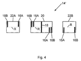
- the reference object 14 ' is designed in three parts with an inner region 20 which is the reference object 14 of Fig. 2 and two outer regions 22A, 22B which are spaced from the inner region 20 and each have two markings 16A, 16B corresponding to the markings 16A, 16B of the reference object 14.
- care must be taken that their reference lines R are aligned with the reference line R of the inner region 20.
- the markings 16B of the outer regions 22A, 22B extend to the reference line R, while the markings 16A are spaced so far from the reference line R that a scanning beam, the reference object 14 'along the reference line R scans, the markings 16A of the outer areas 22A, 22B also not detected.
- the alignment of the laser scanner 10 is carried out in a two-stage process, wherein the first stage with respect to Fig. 2 and 3 In this case, only the markings 16A, 16B, 18 of the inner region 20 are taken into account.
- the external areas 22A, 22B are additionally taken into account in a second stage, whereby instead of the markings 16A, 16B of the interior area 20, only the markings 16A, 16B of the exterior areas 22A, 22B are usefully considered.
- both embodiments may be required to adjust the distance of the markers 16A from the reference line R and possibly also the distance of the markers 16B, 16C from the reference line R to the distance. This can be done, for example, by masking the end regions of the markings 16A, 16B, 16C facing the reference line R with the aid of non-reflective material. In order to ensure correct coverage, the regions of the markings 16A, 16B, 16C to be masked off can be marked on the reference object 14, 14 'by corresponding distance-specific auxiliary markings.
- the alignment of the laser scanner 10 can be done manually by outputting user instructions based on the scan pattern and by a user performs the corresponding changes of orientation by means of the adjusting device.
- the user instructions may be that the scanning pattern is reproduced by means of a suitable display device.
- FIGS Fig. 3 explained contexts issued thereon correction instructions for adjusting the pitch angle or the roll angle, which instructions should at least also contain information about the direction of the change. If a quantitative evaluation of the scanning patterns is possible, for example on the basis of the wedge-shaped markings 16C, the user instruction can also include information about the extent of the necessary adjustments.
- the output of the user instructions can be done optically and / or acoustically.
- the adjusting device is designed for automatic adjustment and connected to the evaluation unit, so that determined by the evaluation unit required adjustment movements are transmitted to the adjustment and executed by this.
- individually manufactured reference objects can also be used instead of the prefabricated reference objects 14, 14 ', for example, by temporarily attaching the necessary markings to a stationary object, for example a wall, at the installation location of the laser scanner.
Landscapes
- Physics & Mathematics (AREA)
- Engineering & Computer Science (AREA)
- Electromagnetism (AREA)
- Computer Networks & Wireless Communication (AREA)
- General Physics & Mathematics (AREA)
- Radar, Positioning & Navigation (AREA)
- Remote Sensing (AREA)
- Length Measuring Devices By Optical Means (AREA)
- Optical Radar Systems And Details Thereof (AREA)
- Laser Beam Processing (AREA)
- Mechanical Optical Scanning Systems (AREA)
Applications Claiming Priority (1)
| Application Number | Priority Date | Filing Date | Title |
|---|---|---|---|
| DE102015119707.3A DE102015119707B8 (de) | 2015-11-16 | 2015-11-16 | Verfahren zum Ausrichten eines Laserscanners und Laserscanneranordnung |
Publications (3)
| Publication Number | Publication Date |
|---|---|
| EP3176606A2 true EP3176606A2 (fr) | 2017-06-07 |
| EP3176606A3 EP3176606A3 (fr) | 2017-11-29 |
| EP3176606B1 EP3176606B1 (fr) | 2019-07-31 |
Family
ID=57178310
Family Applications (1)
| Application Number | Title | Priority Date | Filing Date |
|---|---|---|---|
| EP16194669.4A Active EP3176606B1 (fr) | 2015-11-16 | 2016-10-19 | Procédé destiné à l'alignement d'un scanner laser |
Country Status (3)
| Country | Link |
|---|---|
| EP (1) | EP3176606B1 (fr) |
| JP (1) | JP6343325B2 (fr) |
| DE (1) | DE102015119707B8 (fr) |
Cited By (4)
| Publication number | Priority date | Publication date | Assignee | Title |
|---|---|---|---|---|
| WO2019211209A1 (fr) * | 2018-05-04 | 2019-11-07 | Valeo Schalter Und Sensoren Gmbh | Procédé pour déterminer une position angulaire d'un capteur optoélectronique et banc d'essai |
| WO2020002778A1 (fr) * | 2018-06-28 | 2020-01-02 | Angular Velocity Oy | Procédé et système d'étalonnage d'un capteur |
| EP3693927A1 (fr) * | 2019-02-05 | 2020-08-12 | Sick Ag | Alignement d'une caméra à balayage linéaire avec des triangles comme cibles d'alignement |
| WO2021170292A1 (fr) * | 2020-02-27 | 2021-09-02 | Sew-Eurodrive Gmbh & Co. Kg | Dispositif et procédé d'étalonnage d'un capteur numérique |
Families Citing this family (6)
| Publication number | Priority date | Publication date | Assignee | Title |
|---|---|---|---|---|
| JP7139184B2 (ja) * | 2018-08-01 | 2022-09-20 | 株式会社トプコン | 測量システム、計測モジュール、および測量方法 |
| JP2020024142A (ja) * | 2018-08-07 | 2020-02-13 | 日本電信電話株式会社 | 計測校正装置、計測校正方法、及びプログラム |
| KR102186929B1 (ko) * | 2018-12-18 | 2020-12-04 | 주식회사 엠알케이 | 고점착, 광확산 기능과 다양한 양면 이형 점착력을 가진 기능성 실리콘 점착제 및 이를 이용한 필름 |
| KR102080310B1 (ko) * | 2019-02-28 | 2020-02-21 | 한화시스템 주식회사 | 위상 배열 레이더의 표적 탐지 방법 및 기록 매체 |
| DE102020117428A1 (de) | 2020-07-02 | 2022-01-05 | Sick Ag | Sensorvorrichtung und Ausrichtverfahren |
| DE202020103821U1 (de) | 2020-07-02 | 2021-10-06 | Sick Ag | Sensorvorrichtung |
Citations (3)
| Publication number | Priority date | Publication date | Assignee | Title |
|---|---|---|---|---|
| DE10122664A1 (de) | 2001-05-10 | 2002-11-14 | Ibeo Automobile Sensor Gmbh | Kalibrierverfahren |
| DE10217295A1 (de) | 2002-04-18 | 2003-11-06 | Ibeo Automobile Sensor Gmbh | Bestimmung der Ausrichtung eines optoelektronischen Sensors |
| DE19902287B4 (de) | 1999-01-21 | 2009-04-30 | Volkswagen Ag | Verfahren und Anordnung zur automatischen Justage eines Laserscanner-Sensors |
Family Cites Families (10)
| Publication number | Priority date | Publication date | Assignee | Title |
|---|---|---|---|---|
| US4330212A (en) * | 1978-12-18 | 1982-05-18 | Grumman Aerospace Corporation | Triaxis laser alignment system and method |
| JPH07198382A (ja) * | 1993-12-28 | 1995-08-01 | Nikon Corp | レーザ測量システム |
| JPH08285594A (ja) * | 1995-04-14 | 1996-11-01 | Nikon Corp | レーザ投光装置 |
| JPH10318751A (ja) * | 1997-05-20 | 1998-12-04 | Nikon Corp | 遠隔操作可能なレーザ投光装置 |
| JP3636343B2 (ja) * | 1998-08-27 | 2005-04-06 | オムロン株式会社 | 測距装置の2次元軸調整方法 |
| JP2004317507A (ja) * | 2003-04-04 | 2004-11-11 | Omron Corp | 監視装置の軸調整方法 |
| EP1584946A3 (fr) * | 2004-04-02 | 2006-03-22 | Omron Corporation | Méthode pour le réglage de l'axe optique des capteurs optiques |
| WO2012048420A1 (fr) * | 2010-10-15 | 2012-04-19 | Silonex Inc. | Système et procédé de positionnement optique |
| DE102012100324B4 (de) * | 2012-01-16 | 2024-03-28 | Vorwerk & Co. Interholding Gmbh | Selbsttätig verfahrbares Gerät sowie Verfahren zur Bestimmung der Neigung eines solchen Gerätes und/oder zur Wandverfolgung und/oder zum Annähern an ein Objekt |
| DE102012102651B3 (de) * | 2012-03-27 | 2013-07-18 | Jenoptik Robot Gmbh | Prüfvorrichtung und Prüfverfahren für ein Verkehrsüberwachungsgerät mit einem Laserscanner |
-
2015
- 2015-11-16 DE DE102015119707.3A patent/DE102015119707B8/de not_active Expired - Fee Related
-
2016
- 2016-10-19 EP EP16194669.4A patent/EP3176606B1/fr active Active
- 2016-11-09 JP JP2016218547A patent/JP6343325B2/ja active Active
Patent Citations (3)
| Publication number | Priority date | Publication date | Assignee | Title |
|---|---|---|---|---|
| DE19902287B4 (de) | 1999-01-21 | 2009-04-30 | Volkswagen Ag | Verfahren und Anordnung zur automatischen Justage eines Laserscanner-Sensors |
| DE10122664A1 (de) | 2001-05-10 | 2002-11-14 | Ibeo Automobile Sensor Gmbh | Kalibrierverfahren |
| DE10217295A1 (de) | 2002-04-18 | 2003-11-06 | Ibeo Automobile Sensor Gmbh | Bestimmung der Ausrichtung eines optoelektronischen Sensors |
Cited By (5)
| Publication number | Priority date | Publication date | Assignee | Title |
|---|---|---|---|---|
| WO2019211209A1 (fr) * | 2018-05-04 | 2019-11-07 | Valeo Schalter Und Sensoren Gmbh | Procédé pour déterminer une position angulaire d'un capteur optoélectronique et banc d'essai |
| KR20210003879A (ko) * | 2018-05-04 | 2021-01-12 | 발레오 샬터 운트 센소렌 게엠베아 | 광전자 센서의 각도 위치를 결정하는 방법 및 테스트 스탠드 |
| WO2020002778A1 (fr) * | 2018-06-28 | 2020-01-02 | Angular Velocity Oy | Procédé et système d'étalonnage d'un capteur |
| EP3693927A1 (fr) * | 2019-02-05 | 2020-08-12 | Sick Ag | Alignement d'une caméra à balayage linéaire avec des triangles comme cibles d'alignement |
| WO2021170292A1 (fr) * | 2020-02-27 | 2021-09-02 | Sew-Eurodrive Gmbh & Co. Kg | Dispositif et procédé d'étalonnage d'un capteur numérique |
Also Published As
| Publication number | Publication date |
|---|---|
| EP3176606B1 (fr) | 2019-07-31 |
| DE102015119707B3 (de) | 2017-05-18 |
| JP6343325B2 (ja) | 2018-06-13 |
| JP2017122712A (ja) | 2017-07-13 |
| EP3176606A3 (fr) | 2017-11-29 |
| DE102015119707B8 (de) | 2017-08-24 |
Similar Documents
| Publication | Publication Date | Title |
|---|---|---|
| EP3176606B1 (fr) | Procédé destiné à l'alignement d'un scanner laser | |
| DE102004015785B4 (de) | Verfahren zur Bestimmung der Abmessung eines Querschnitts eines Flachkabels oder eines Sektorleiters | |
| EP2093537B1 (fr) | Système et procédé pour déterminer l'alignement de deux pièces de machine rotatives | |
| EP1711777B1 (fr) | Procede pour determiner la position et le mouvement relativ d'un objet dans un espace | |
| DE102012102651B3 (de) | Prüfvorrichtung und Prüfverfahren für ein Verkehrsüberwachungsgerät mit einem Laserscanner | |
| EP2668468A1 (fr) | Étalonnage de détecteurs de coupe optique laser simultanément à la mesure | |
| EP3745081B1 (fr) | Détecteur de position et procédé de détermination tridimensionnelle de position | |
| WO2008071251A2 (fr) | Dispositif pour détecter des mouvements et des forces | |
| DE19732668C2 (de) | Vorrichtung und Verfahren zur Kalibrierung von Strahlabtastvorrichtungen | |
| EP1640688A1 (fr) | Procédé et dispositif pour mesurer la surface d'un objet en trois dimensions | |
| EP3438525B1 (fr) | Dispositif d'éclairage pour un dispositif de simulation d'un accident de véhicule | |
| EP2626672A1 (fr) | Agencement à plusieurs unités de balayage d'un dispositif de mesure de position | |
| WO2005071434A1 (fr) | Procede et dispositif pour realiser l'alignement angulaire d'un capteur dans un vehicule automobile | |
| EP3575741B1 (fr) | Procédé de mesure sans contact d'un bord de pièce à usiner | |
| DE102014215439B4 (de) | Verfahren zum Herstellen einer Struktur | |
| DE102017212782A1 (de) | In-Situ-Laserspektrometer | |
| EP3443304B1 (fr) | Dispositif de mesure de position et procede de fonctionnement d'un dispositif de mesure de position | |
| EP4111227B1 (fr) | Dispositif et procédé d'étalonnage d'un capteur numérique | |
| DE102014215633A1 (de) | Positionsmesseinrichtung | |
| DE102021202951A1 (de) | Medizinisches Gerät zur Ermittlung der räumlichen Lage eines flächig ausgebildeten Markers | |
| EP2972111B1 (fr) | Procédé d'application d'une structure sur un élément, notamment sur un élément d'un système de mesure angulaire | |
| EP2335029B1 (fr) | Dispositif de mesure de position optique | |
| EP1136787A1 (fr) | Reproduction d'un objet avec compensation de la distance ( taille, couleur ) | |
| DE102005000813B4 (de) | Verfahren zur Strahlkalibrierung und Verwendungen eines Kalibrierungskörpers | |
| EP3798570B1 (fr) | Procédé d'étalonnage d'un système de mesure optique, système de mesure optique et objet d'étalonnage pour un système de mesure optique |
Legal Events
| Date | Code | Title | Description |
|---|---|---|---|
| AK | Designated contracting states |
Kind code of ref document: A2 Designated state(s): AL AT BE BG CH CY CZ DE DK EE ES FI FR GB GR HR HU IE IS IT LI LT LU LV MC MK MT NL NO PL PT RO RS SE SI SK SM TR |
|
| AX | Request for extension of the european patent |
Extension state: BA ME |
|
| PUAI | Public reference made under article 153(3) epc to a published international application that has entered the european phase |
Free format text: ORIGINAL CODE: 0009012 |
|
| STAA | Information on the status of an ep patent application or granted ep patent |
Free format text: STATUS: THE APPLICATION HAS BEEN PUBLISHED |
|
| PUAL | Search report despatched |
Free format text: ORIGINAL CODE: 0009013 |
|
| AK | Designated contracting states |
Kind code of ref document: A3 Designated state(s): AL AT BE BG CH CY CZ DE DK EE ES FI FR GB GR HR HU IE IS IT LI LT LU LV MC MK MT NL NO PL PT RO RS SE SI SK SM TR |
|
| AX | Request for extension of the european patent |
Extension state: BA ME |
|
| RIC1 | Information provided on ipc code assigned before grant |
Ipc: G01S 7/497 20060101ALI20171020BHEP Ipc: G01S 17/42 20060101AFI20171020BHEP |
|
| STAA | Information on the status of an ep patent application or granted ep patent |
Free format text: STATUS: REQUEST FOR EXAMINATION WAS MADE |
|
| 17P | Request for examination filed |
Effective date: 20180404 |
|
| RBV | Designated contracting states (corrected) |
Designated state(s): AL AT BE BG CH CY CZ DE DK EE ES FI FR GB GR HR HU IE IS IT LI LT LU LV MC MK MT NL NO PL PT RO RS SE SI SK SM TR |
|
| STAA | Information on the status of an ep patent application or granted ep patent |
Free format text: STATUS: EXAMINATION IS IN PROGRESS |
|
| 17Q | First examination report despatched |
Effective date: 20180622 |
|
| GRAP | Despatch of communication of intention to grant a patent |
Free format text: ORIGINAL CODE: EPIDOSNIGR1 |
|
| STAA | Information on the status of an ep patent application or granted ep patent |
Free format text: STATUS: GRANT OF PATENT IS INTENDED |
|
| INTG | Intention to grant announced |
Effective date: 20190218 |
|
| GRAS | Grant fee paid |
Free format text: ORIGINAL CODE: EPIDOSNIGR3 |
|
| GRAA | (expected) grant |
Free format text: ORIGINAL CODE: 0009210 |
|
| STAA | Information on the status of an ep patent application or granted ep patent |
Free format text: STATUS: THE PATENT HAS BEEN GRANTED |
|
| AK | Designated contracting states |
Kind code of ref document: B1 Designated state(s): AL AT BE BG CH CY CZ DE DK EE ES FI FR GB GR HR HU IE IS IT LI LT LU LV MC MK MT NL NO PL PT RO RS SE SI SK SM TR |
|
| REG | Reference to a national code |
Ref country code: CH Ref legal event code: EP Ref country code: GB Ref legal event code: FG4D Free format text: NOT ENGLISH |
|
| REG | Reference to a national code |
Ref country code: DE Ref legal event code: R096 Ref document number: 502016005781 Country of ref document: DE |
|
| REG | Reference to a national code |
Ref country code: AT Ref legal event code: REF Ref document number: 1161506 Country of ref document: AT Kind code of ref document: T Effective date: 20190815 |
|
| REG | Reference to a national code |
Ref country code: IE Ref legal event code: FG4D Free format text: LANGUAGE OF EP DOCUMENT: GERMAN |
|
| REG | Reference to a national code |
Ref country code: NL Ref legal event code: MP Effective date: 20190731 |
|
| REG | Reference to a national code |
Ref country code: LT Ref legal event code: MG4D |
|
| PG25 | Lapsed in a contracting state [announced via postgrant information from national office to epo] |
Ref country code: SE Free format text: LAPSE BECAUSE OF FAILURE TO SUBMIT A TRANSLATION OF THE DESCRIPTION OR TO PAY THE FEE WITHIN THE PRESCRIBED TIME-LIMIT Effective date: 20190731 Ref country code: HR Free format text: LAPSE BECAUSE OF FAILURE TO SUBMIT A TRANSLATION OF THE DESCRIPTION OR TO PAY THE FEE WITHIN THE PRESCRIBED TIME-LIMIT Effective date: 20190731 Ref country code: NL Free format text: LAPSE BECAUSE OF FAILURE TO SUBMIT A TRANSLATION OF THE DESCRIPTION OR TO PAY THE FEE WITHIN THE PRESCRIBED TIME-LIMIT Effective date: 20190731 Ref country code: FI Free format text: LAPSE BECAUSE OF FAILURE TO SUBMIT A TRANSLATION OF THE DESCRIPTION OR TO PAY THE FEE WITHIN THE PRESCRIBED TIME-LIMIT Effective date: 20190731 Ref country code: LT Free format text: LAPSE BECAUSE OF FAILURE TO SUBMIT A TRANSLATION OF THE DESCRIPTION OR TO PAY THE FEE WITHIN THE PRESCRIBED TIME-LIMIT Effective date: 20190731 Ref country code: BG Free format text: LAPSE BECAUSE OF FAILURE TO SUBMIT A TRANSLATION OF THE DESCRIPTION OR TO PAY THE FEE WITHIN THE PRESCRIBED TIME-LIMIT Effective date: 20191031 Ref country code: NO Free format text: LAPSE BECAUSE OF FAILURE TO SUBMIT A TRANSLATION OF THE DESCRIPTION OR TO PAY THE FEE WITHIN THE PRESCRIBED TIME-LIMIT Effective date: 20191031 Ref country code: PT Free format text: LAPSE BECAUSE OF FAILURE TO SUBMIT A TRANSLATION OF THE DESCRIPTION OR TO PAY THE FEE WITHIN THE PRESCRIBED TIME-LIMIT Effective date: 20191202 |
|
| RAP2 | Party data changed (patent owner data changed or rights of a patent transferred) |
Owner name: SICK AG |
|
| PG25 | Lapsed in a contracting state [announced via postgrant information from national office to epo] |
Ref country code: AL Free format text: LAPSE BECAUSE OF FAILURE TO SUBMIT A TRANSLATION OF THE DESCRIPTION OR TO PAY THE FEE WITHIN THE PRESCRIBED TIME-LIMIT Effective date: 20190731 Ref country code: GR Free format text: LAPSE BECAUSE OF FAILURE TO SUBMIT A TRANSLATION OF THE DESCRIPTION OR TO PAY THE FEE WITHIN THE PRESCRIBED TIME-LIMIT Effective date: 20191101 Ref country code: LV Free format text: LAPSE BECAUSE OF FAILURE TO SUBMIT A TRANSLATION OF THE DESCRIPTION OR TO PAY THE FEE WITHIN THE PRESCRIBED TIME-LIMIT Effective date: 20190731 Ref country code: RS Free format text: LAPSE BECAUSE OF FAILURE TO SUBMIT A TRANSLATION OF THE DESCRIPTION OR TO PAY THE FEE WITHIN THE PRESCRIBED TIME-LIMIT Effective date: 20190731 |
|
| PG25 | Lapsed in a contracting state [announced via postgrant information from national office to epo] |
Ref country code: TR Free format text: LAPSE BECAUSE OF FAILURE TO SUBMIT A TRANSLATION OF THE DESCRIPTION OR TO PAY THE FEE WITHIN THE PRESCRIBED TIME-LIMIT Effective date: 20190731 |
|
| PG25 | Lapsed in a contracting state [announced via postgrant information from national office to epo] |
Ref country code: IT Free format text: LAPSE BECAUSE OF FAILURE TO SUBMIT A TRANSLATION OF THE DESCRIPTION OR TO PAY THE FEE WITHIN THE PRESCRIBED TIME-LIMIT Effective date: 20190731 Ref country code: RO Free format text: LAPSE BECAUSE OF FAILURE TO SUBMIT A TRANSLATION OF THE DESCRIPTION OR TO PAY THE FEE WITHIN THE PRESCRIBED TIME-LIMIT Effective date: 20190731 Ref country code: DK Free format text: LAPSE BECAUSE OF FAILURE TO SUBMIT A TRANSLATION OF THE DESCRIPTION OR TO PAY THE FEE WITHIN THE PRESCRIBED TIME-LIMIT Effective date: 20190731 Ref country code: PL Free format text: LAPSE BECAUSE OF FAILURE TO SUBMIT A TRANSLATION OF THE DESCRIPTION OR TO PAY THE FEE WITHIN THE PRESCRIBED TIME-LIMIT Effective date: 20190731 Ref country code: EE Free format text: LAPSE BECAUSE OF FAILURE TO SUBMIT A TRANSLATION OF THE DESCRIPTION OR TO PAY THE FEE WITHIN THE PRESCRIBED TIME-LIMIT Effective date: 20190731 |
|
| PG25 | Lapsed in a contracting state [announced via postgrant information from national office to epo] |
Ref country code: CZ Free format text: LAPSE BECAUSE OF FAILURE TO SUBMIT A TRANSLATION OF THE DESCRIPTION OR TO PAY THE FEE WITHIN THE PRESCRIBED TIME-LIMIT Effective date: 20190731 Ref country code: MC Free format text: LAPSE BECAUSE OF FAILURE TO SUBMIT A TRANSLATION OF THE DESCRIPTION OR TO PAY THE FEE WITHIN THE PRESCRIBED TIME-LIMIT Effective date: 20190731 Ref country code: SM Free format text: LAPSE BECAUSE OF FAILURE TO SUBMIT A TRANSLATION OF THE DESCRIPTION OR TO PAY THE FEE WITHIN THE PRESCRIBED TIME-LIMIT Effective date: 20190731 Ref country code: SK Free format text: LAPSE BECAUSE OF FAILURE TO SUBMIT A TRANSLATION OF THE DESCRIPTION OR TO PAY THE FEE WITHIN THE PRESCRIBED TIME-LIMIT Effective date: 20190731 Ref country code: IS Free format text: LAPSE BECAUSE OF FAILURE TO SUBMIT A TRANSLATION OF THE DESCRIPTION OR TO PAY THE FEE WITHIN THE PRESCRIBED TIME-LIMIT Effective date: 20200224 |
|
| REG | Reference to a national code |
Ref country code: DE Ref legal event code: R097 Ref document number: 502016005781 Country of ref document: DE |
|
| PLBE | No opposition filed within time limit |
Free format text: ORIGINAL CODE: 0009261 |
|
| STAA | Information on the status of an ep patent application or granted ep patent |
Free format text: STATUS: NO OPPOSITION FILED WITHIN TIME LIMIT |
|
| PG2D | Information on lapse in contracting state deleted |
Ref country code: IS |
|
| PG25 | Lapsed in a contracting state [announced via postgrant information from national office to epo] |
Ref country code: LU Free format text: LAPSE BECAUSE OF NON-PAYMENT OF DUE FEES Effective date: 20191019 Ref country code: IS Free format text: LAPSE BECAUSE OF FAILURE TO SUBMIT A TRANSLATION OF THE DESCRIPTION OR TO PAY THE FEE WITHIN THE PRESCRIBED TIME-LIMIT Effective date: 20191030 |
|
| 26N | No opposition filed |
Effective date: 20200603 |
|
| REG | Reference to a national code |
Ref country code: BE Ref legal event code: MM Effective date: 20191031 |
|
| PG25 | Lapsed in a contracting state [announced via postgrant information from national office to epo] |
Ref country code: BE Free format text: LAPSE BECAUSE OF NON-PAYMENT OF DUE FEES Effective date: 20191031 Ref country code: SI Free format text: LAPSE BECAUSE OF FAILURE TO SUBMIT A TRANSLATION OF THE DESCRIPTION OR TO PAY THE FEE WITHIN THE PRESCRIBED TIME-LIMIT Effective date: 20190731 |
|
| PG25 | Lapsed in a contracting state [announced via postgrant information from national office to epo] |
Ref country code: IE Free format text: LAPSE BECAUSE OF NON-PAYMENT OF DUE FEES Effective date: 20191019 Ref country code: ES Free format text: LAPSE BECAUSE OF FAILURE TO SUBMIT A TRANSLATION OF THE DESCRIPTION OR TO PAY THE FEE WITHIN THE PRESCRIBED TIME-LIMIT Effective date: 20190731 |
|
| PG25 | Lapsed in a contracting state [announced via postgrant information from national office to epo] |
Ref country code: CY Free format text: LAPSE BECAUSE OF FAILURE TO SUBMIT A TRANSLATION OF THE DESCRIPTION OR TO PAY THE FEE WITHIN THE PRESCRIBED TIME-LIMIT Effective date: 20190731 |
|
| GBPC | Gb: european patent ceased through non-payment of renewal fee |
Effective date: 20201019 |
|
| PG25 | Lapsed in a contracting state [announced via postgrant information from national office to epo] |
Ref country code: HU Free format text: LAPSE BECAUSE OF FAILURE TO SUBMIT A TRANSLATION OF THE DESCRIPTION OR TO PAY THE FEE WITHIN THE PRESCRIBED TIME-LIMIT; INVALID AB INITIO Effective date: 20161019 Ref country code: MT Free format text: LAPSE BECAUSE OF FAILURE TO SUBMIT A TRANSLATION OF THE DESCRIPTION OR TO PAY THE FEE WITHIN THE PRESCRIBED TIME-LIMIT Effective date: 20190731 |
|
| PG25 | Lapsed in a contracting state [announced via postgrant information from national office to epo] |
Ref country code: GB Free format text: LAPSE BECAUSE OF NON-PAYMENT OF DUE FEES Effective date: 20201019 |
|
| PG25 | Lapsed in a contracting state [announced via postgrant information from national office to epo] |
Ref country code: MK Free format text: LAPSE BECAUSE OF FAILURE TO SUBMIT A TRANSLATION OF THE DESCRIPTION OR TO PAY THE FEE WITHIN THE PRESCRIBED TIME-LIMIT Effective date: 20190731 |
|
| PGFP | Annual fee paid to national office [announced via postgrant information from national office to epo] |
Ref country code: AT Payment date: 20221018 Year of fee payment: 7 |
|
| REG | Reference to a national code |
Ref country code: AT Ref legal event code: MM01 Ref document number: 1161506 Country of ref document: AT Kind code of ref document: T Effective date: 20231019 |
|
| PG25 | Lapsed in a contracting state [announced via postgrant information from national office to epo] |
Ref country code: AT Free format text: LAPSE BECAUSE OF NON-PAYMENT OF DUE FEES Effective date: 20231019 |
|
| PG25 | Lapsed in a contracting state [announced via postgrant information from national office to epo] |
Ref country code: AT Free format text: LAPSE BECAUSE OF NON-PAYMENT OF DUE FEES Effective date: 20231019 |
|
| REG | Reference to a national code |
Ref country code: CH Ref legal event code: U11 Free format text: ST27 STATUS EVENT CODE: U-0-0-U10-U11 (AS PROVIDED BY THE NATIONAL OFFICE) Effective date: 20251101 |
|
| PGFP | Annual fee paid to national office [announced via postgrant information from national office to epo] |
Ref country code: DE Payment date: 20251020 Year of fee payment: 10 |
|
| PGFP | Annual fee paid to national office [announced via postgrant information from national office to epo] |
Ref country code: FR Payment date: 20251022 Year of fee payment: 10 |
|
| PGFP | Annual fee paid to national office [announced via postgrant information from national office to epo] |
Ref country code: CH Payment date: 20251101 Year of fee payment: 10 |