EP3178759B1 - Système de convoyeur à rouleaux - Google Patents
Système de convoyeur à rouleaux Download PDFInfo
- Publication number
- EP3178759B1 EP3178759B1 EP15198158.6A EP15198158A EP3178759B1 EP 3178759 B1 EP3178759 B1 EP 3178759B1 EP 15198158 A EP15198158 A EP 15198158A EP 3178759 B1 EP3178759 B1 EP 3178759B1
- Authority
- EP
- European Patent Office
- Prior art keywords
- transport
- rotation
- axis
- transport roller
- conveying system
- Prior art date
- Legal status (The legal status is an assumption and is not a legal conclusion. Google has not performed a legal analysis and makes no representation as to the accuracy of the status listed.)
- Active
Links
- 230000005484 gravity Effects 0.000 claims description 11
- 238000000034 method Methods 0.000 claims description 11
- 230000002093 peripheral effect Effects 0.000 claims 2
- 230000032258 transport Effects 0.000 description 230
- 239000000243 solution Substances 0.000 description 9
- 230000001174 ascending effect Effects 0.000 description 5
- 230000006378 damage Effects 0.000 description 5
- 239000000463 material Substances 0.000 description 5
- 238000010276 construction Methods 0.000 description 3
- 238000012423 maintenance Methods 0.000 description 3
- 238000009825 accumulation Methods 0.000 description 2
- 230000005540 biological transmission Effects 0.000 description 2
- 238000005520 cutting process Methods 0.000 description 2
- 230000001419 dependent effect Effects 0.000 description 2
- 238000009826 distribution Methods 0.000 description 2
- 238000003860 storage Methods 0.000 description 2
- 235000004443 Ricinus communis Nutrition 0.000 description 1
- 240000000528 Ricinus communis Species 0.000 description 1
- 230000009056 active transport Effects 0.000 description 1
- 238000011109 contamination Methods 0.000 description 1
- 238000002347 injection Methods 0.000 description 1
- 239000007924 injection Substances 0.000 description 1
- 238000004519 manufacturing process Methods 0.000 description 1
- 238000005192 partition Methods 0.000 description 1
- 230000000717 retained effect Effects 0.000 description 1
- 238000000926 separation method Methods 0.000 description 1
- 238000010008 shearing Methods 0.000 description 1
- 239000007787 solid Substances 0.000 description 1
- 230000001960 triggered effect Effects 0.000 description 1
Images




Classifications
-
- B—PERFORMING OPERATIONS; TRANSPORTING
- B65—CONVEYING; PACKING; STORING; HANDLING THIN OR FILAMENTARY MATERIAL
- B65G—TRANSPORT OR STORAGE DEVICES, e.g. CONVEYORS FOR LOADING OR TIPPING, SHOP CONVEYOR SYSTEMS OR PNEUMATIC TUBE CONVEYORS
- B65G13/00—Roller-ways
- B65G13/02—Roller-ways having driven rollers
- B65G13/06—Roller driving means
- B65G13/065—Roller driving means with displacement of the roller
-
- B—PERFORMING OPERATIONS; TRANSPORTING
- B65—CONVEYING; PACKING; STORING; HANDLING THIN OR FILAMENTARY MATERIAL
- B65G—TRANSPORT OR STORAGE DEVICES, e.g. CONVEYORS FOR LOADING OR TIPPING, SHOP CONVEYOR SYSTEMS OR PNEUMATIC TUBE CONVEYORS
- B65G13/00—Roller-ways
- B65G13/08—Roller-ways of curved form; with branch-offs
- B65G13/10—Switching arrangements
-
- B—PERFORMING OPERATIONS; TRANSPORTING
- B65—CONVEYING; PACKING; STORING; HANDLING THIN OR FILAMENTARY MATERIAL
- B65G—TRANSPORT OR STORAGE DEVICES, e.g. CONVEYORS FOR LOADING OR TIPPING, SHOP CONVEYOR SYSTEMS OR PNEUMATIC TUBE CONVEYORS
- B65G13/00—Roller-ways
- B65G13/02—Roller-ways having driven rollers
- B65G13/06—Roller driving means
- B65G13/071—Roller driving means with frictional engagement
Definitions
- the invention relates to the technical field of conveyor systems for goods, in particular to conveyor systems that allow directional conveying.
- a directed conveying of goods in adjustable transport directions on a conveyor line is of particular importance in sorting systems, in particular mail and baggage sorting systems, and manufacturing systems.
- a solution integrated into the conveyor line for setting the transport directions can make expensive components, such as a corner transfer device, superfluous.
- the conveying is carried out gently, i.e. without collisions with an edge of the conveying path or other components, which could damage the goods.
- goods often collect on one side of the accumulation after being dropped due to their inertia, which makes it difficult to fully utilize the width of the transport chute as storage space.
- the state of the art for directed conveying is the use of swivel rollers which are mounted on a vertical axis. Around this axis, the swivel castors are changed in their angular setting individually or as a line via handlebars, for example by WO2014 / 066838 A1 is known.
- Another solution uses orthogonally freely rotating rollers. If active conveyance is to be carried out in a specific direction, additional roles are run up to a good.
- Another solution uses a cylindrical roller, which is arranged at an angle in a link belt. A transverse transport is triggered by bringing a friction surface onto the link belt from below, as a result of which the cylindrical roller executes a forced movement.
- deflector plates attached to one side of the slide are used to hold the goods on a ricochet, give an impulse away from the accumulation side.
- the transport chute is inclined slightly transversely in order to take advantage of gravity.
- the present invention is therefore based on the object of providing a technically simple, robust and goods-friendly solution for the directed conveying of goods with a wide range of uses. This object is achieved by the solutions described in the independent claims.
- the solution according to the invention provides a conveyor system which is suitable for transporting goods on a transport level.
- the conveyor system comprises at least one transport roller which is provided for the transport of the goods and which has a circumferential surface like a segment of a spherical surface at least in an area provided for contact with the goods.
- the at least one transport roller can be rotated about its axis of rotation and the conveyor system has at least one pivot axis about which the axis of rotation can be adjusted by rotation.
- the at least one pivot axis can be arranged essentially parallel to the transport plane. This enables the Swivel axis parallel below the transport plane and allows rotation of the swivel axis to deflect an item without impairing its transport path on the conveyor line.
- the axis of rotation and the at least one pivot axis can enclose an angle of the axis of rotation.
- the at least one transport roller can be drivable.
- the at least one transport roller can in particular be drivable about its axis of rotation with a drive in the transport roller and / or a drive means and / or gravity conveyor arranged below the transport roller.
- gravity conveying enables a particularly low-energy drive while at the same time overcoming a height difference, for example on a transport chute as an at least partially inclined transport plane.
- the conveyor system can include at least one tilting device with which the axis of rotation of the at least one transport roller can be set at an angle.
- the at least one transport roller can comprise at least one bearing, in particular a roller bearing.
- a cover can be arranged below the transport level, the cover comprising a recess for each transport roller.
- the conveyor system can comprise several transport rollers which are arranged along a width and / or a length of the transport plane .
- the multiple transport rollers can transport a good or multiple goods over the width and / or length of the transport plane.
- the transport rollers can form a roller carpet-like conveyor system.
- the transport roller can be configured in the manner of a sphere or a sphere zone.
- the entire surface of the transport roller is circumferentially in the manner of a spherical surface and is therefore intended for contact with the goods.
- the transport roller can be rotated completely around its pivot axis.
- the surface of the transport roller can circumferentially resemble a spherical surface in an area provided over the area provided for contact with the goods be, whereby the transport plane and another tangential surface always have the same distance.
- the one or more transport rollers can be mounted on at least one shaft.
- simultaneous rotation of the transport rollers mounted on this shaft can be achieved particularly easily; when mounted on more than one shaft, individual rotation of the individual shafts and thus of one or more transport rollers mounted on said shaft can be achieved particularly easily will.
- the at least one shaft can be positively and / or non-positively connectable to the at least one transport roller.
- the shaft and transport roller are thus secured against twisting, which allows a rotational movement to be efficiently passed on via the shaft to the at least one transport roller.
- the above-mentioned object is achieved by a method for transporting goods with a conveyor system on a transport level, wherein the conveyor system comprises at least one transport roller provided for transporting the goods, which has a roller at least in an area provided for contact with the goods having circumferential spherical surface section-like surface.
- the transport roller can be rotated about its axis of rotation and the conveyor system has at least one pivot axis about which the axis of rotation can be adjusted by rotation.
- the procedure comprises the method step of rotating the at least one transport roller, in particular with a drive in the transport roller and / or a drive means and / or gravity feed arranged below the transport roller.
- the axis of rotation of the at least one transport roller can be inclined by its axis of rotation angle and / or the axis of rotation can be adjusted by rotating around its pivot axis.
- a common rotating drive of more than one transport roller can take place.
- the common rotating drive can take place particularly easily if more than one transport roller is mounted on a shaft.
- two or more of the transport rollers can have parallel and / or non-parallel axes of rotation, parallel and / or identical swivel axes and the same and / or different swivel axis angles.
- FIG 1 shows schematically a side view of a conveyor system 2 according to a preferred embodiment of the invention.
- the conveyor system 2 is designed and suitable for transporting a good 4, in particular piece goods such as suitcases, luggage and mail, on a transport level 6 and comprises a transport roller 8 provided for transporting a good 4, which has an excellent axis of rotation 10.
- the transport roller 8 can be rotated about its axis of rotation 10 and can be driven with a drive means 12 arranged below the transport roller 8, for example a drive roller or a drive belt, in particular about its axis of rotation 10.
- the transport roller 8 has a shape derived from a ball, so that the transport roller 8 has a circumferential surface 14 similar to the surface of a spherical surface at least in an area provided for contact with the item 4. How the shape of the transport roller 8 is derived from a ball is indicated by a partially broken circle 16.
- the transport roller 8 shown is a spherical disk, which is cut out from two parallel cutting planes 18 lying orthogonally to the axis of rotation 10.
- the circumferential spherical surface-like surface 14 is a spherical zone as a curved surface part of the indicated sphere.
- a spherical or spherical zone-like transport roller 8 allows a simple construction of the transport rollers 8 and, even when the alignment is changed, always the same type of contact between the transport roller 8 and the goods 4.
- the transport plane 6 is a tangential surface of the transport roller 8, another tangential surface of the transport roller 8 exists the drive means 12. Due to the circumferential spherical surface-like surface 14, the item 4 rests on the transport roller 8 with an almost punctiform contact point 27.
- thrust and slip forces are transmitted from the drive means 12 to the transport roller 8.
- Other possibilities for driving the transport roller 8 are a drive integrated in the transport roller 8 or a drive via gravity conveyance. Push and slip forces always act between the transport roller 8 and the transported goods 4.
- a drive by means of gravity conveyance can be used particularly advantageously on inclined transport levels 6, such as occur, for example, in transport chutes.
- the conveyor system 2 has a pivot axis 20 about which the entire transport roller 8 including its axis of rotation 10 can be adjusted by rotation.
- the pivot axis 20 is arranged essentially parallel to and below the transport plane 6.
- the transport roller 8 is mounted on a shaft 21.
- Rotation axis 10 and pivot axis 20 enclose a rotation axis angle 22. Since the shape of the transport roller 8 is derived from a sphere, the distance between the two tangential surfaces introduced above does not change.
- This material running direction 26 is always referred to below as the main transport direction 26h, a deviation as the deflected transport direction 26a, with a maximum possible angle between the main transport direction 26h and the deflected transport direction 26a when the pivot axis 20 or the shaft 21 rotates is reached by a pivot axis angle of + -90 ° and is equal to the rotation axis angle 22.
- the deflected transport direction 26a and the main transport direction 26h include a steering angle that can be set as a function of both the rotation axis angle 22 and the pivot axis angle.
- the pivot axis angle is changed by the rotation about the pivot axis 20 and is 0 ° or 180 ° if the pivot axis 20 and the rotation axis 10 are located in a plane that is orthogonal to the transport plane 6.
- the pivot axis angle describes the positive or negative deflection of the pivot axis 20, through which the axis of rotation is rotated into the plane of the drawing or out of the plane of the drawing.
- a further description of influencing the material running direction 26 is given in the description of FIG Figure 3 .
- the good 4 only comes into contact with one half of the surface 14, a good contact area 28g; the drive means 12, however, only comes into contact with the other half of the 14, a drive means contact surface 28a.
- the good contact surface 28g and the drive means contact surface 28a are separated by a cut surface 30 which includes the center point of the sphere indicated by the circumference 16 and is oriented orthogonally to the axis of rotation 10.
- a separation of the good contact surface 28g and the drive means contact surface 28a enables the use of different materials, each of which is optimized for an optimal power transmission between the good 4 or the drive means 12 and the transport roller 8.
- the transport roller 8 when rotated about its axis of rotation 10, has an effective radius 32w which is smaller than a spherical radius 32r. It follows from this for a transport roller 8 with its own drive that the speed component in the good running direction 26 remains the same even when it is deflected. As the adjustment increases, the effective radius 32w increases to the extent of the spherical radius 32r. That is, the transverse component of the velocity vector is inherently increased. In the case of a drive via drive means 12, the speed of the drive means 12 must always be adjusted with a larger axis of rotation angle 22 in order to transport the good 4 at a constant speed.
- FIG. 2 shows schematically a side view of a conveyor system 2 according to a preferred embodiment of the invention as in FIG Figure 1 , but with technical details of a transport roller 8.
- the conveyor system 2 comprises a tilting device 34 which is integrated into the transport roller 8 and with which the axis of rotation 10 can be adjusted at the angle of rotation 22 to the pivot axis 20.
- An adjustment of the rotation axis angle 22 takes place in particular on the construction side, since the tilting device 34 is usually only designed for a specific rotation axis angle 22.
- An even wider area of application different maximum deflected transport directions 26a would be made possible by a tilting device 34 which enables the rotation axis angle 22 to be set even after the conveyor system 2 has been put into operation during operation.
- the transport roller 8 comprises a bearing designed as a roller bearing 36.
- a design of the bearing as a plain bearing would also be possible.
- the roller bearing 36 which can be configured, for example, as a ball bearing, and the tilting device 34 are part of a bearing 38 of the transport roller 8.
- Tilting device 34, shaft 21, and in particular pivoting axis 20 and transport roller 8 are designed to be positively and optionally non-positively connectable to one another for additional protection, so that rotational movements are particularly efficient forwarding, since pivoting axis 20, inclination 34 and, in particular, transporting roller 8 and shaft 21 so cannot twist against each other.
- Interlocking interlocking connections are also particularly stable and require little maintenance. They can be implemented particularly easily as injection molded parts. However, the connections could also be designed to be purely frictional.
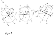
- Figure 3 shows a plan view of three identically configured transport rollers 81, 8m, 8r with differently oriented pivot axes 201, 20m, 20r according to a preferred embodiment of the invention to illustrate how the direction of movement of goods 26 can be influenced.
- the axis of rotation 10m and pivot axis 20m are as already in FIG Figure 1 and 2 shown in a plane, so that a good 4 is transported orthogonally to the pivot axis 20 in the main transport direction 26h.
- the pivot axis 201 of the left transport roller 81 was rotated negatively by 90 °, which is shown in the drawing of FIG Figure 1 and 2 corresponds to turning the axis of rotation 10 out of the plane of the drawing towards the viewer.
- a good 4 is transported to the left in a deflected transport direction 26a, which includes an angle of rotation axis 22 with the main transport direction 26h.
- the pivot axis 20r was positively rotated by 90 °, which is shown in FIG Figure 1 and 2 corresponds to turning the axis of rotation 10 into the plane of the drawing away from the viewer.
- the pivot axis 20 is rotated less than or by + -90 °.
- a support point 27 of a good 4 is always located on the transport roller 8 only on the good contact surface 28g and not on the drive means contact surface 28a. Since there is no greater deflection of the pivot axis 20 than 90 °, there is no mixing of the contact surfaces 28a, 28g.
- a design of the transport roller 8 as a solid ball would allow a complete 360 ° rotation of the pivot axis 20, but the maximum possible angle of the deflected transport direction is already reached after a rotation of + -90 °. In addition, this would also cause the contact surfaces 28a, 28g to mix and thus not allow the use of different materials.
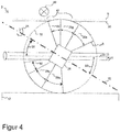
- FIG. 4 shows a cross section of a transport roller 8 of a conveyor system 2 as in FIG Figure 1 and 2 shown with a arranged below the transport plane 6 cover 40 according to a preferred embodiment of the invention.
- the cover 40 comprises a recess 42 for the transport roller 8.
- the recess 42 is circular.
- the circumferential surface 14 of the transport roller 8 is divided into a drive means contact surface 28a, a product contact surface 28g and also includes a protruding surface 42 that does not come into contact with the product 4 or the drive means 12 - even after the rotation of the Pivot axis 20.
- the protruding surface 42 ensures that a perfect spherical surface-like surface 14 of the transport roller 8 protrudes from the cover 40, i.e.
- cover 40 no gap opens between the cover 40 and the transport roller 8, i.e. no catching, squeezing and / or shearing points arise . If a greater rotation of the pivot axis 20 than + -90 ° were possible, no cover 40 could be used.
- the cover 40 protects the conveyor system 2, in particular the bearing 38 with its moving parts, from damage by an item 4 and vice versa and from contamination and operating personnel from injuries.
- the transport roller 8 is derived from a ball with a diameter of 80 mm and the axis of rotation 10 is arranged at an axis of rotation angle 22 of 30 ° to the pivot axis 20.
- the good contact surface 28g extends over an angular extent of precisely the rotation axis angle 22, that is to say 30 °.
- the cover 40 is arranged 2 mm below the transport plane 6, so that the protruding surface 44 has an angular extent of 20 ° or even more - depending on the desired safety margin.
- the drive means contact surface 28a has an angular extent of 35 ° - of which 30 ° are due to the rotation axis angle 22, as well as an additional safety margin of 5 ° to prevent an edge of the transport roller 8 from rubbing on the drive means 12.
- the effective radius 32r is 32.9 mm for the in Figure 4 arrangement shown.
- the shaft 21 is a square with a square cross-section and a side length of 10 mm.
- Figure 5 shows a side view of a plurality of transport rollers 8a, 8b, 8c comprising conveyor system 2 according to a preferred embodiment of the invention.
- the transport rollers 8a, 8b, 8c are arranged along a width of the transport plane 6 on a common shaft 21 with a common and thus identical pivot axis 20, so that the item 4 is simultaneously deflected by several transport rollers 8a, 8b, 8c.
- the good 4 rests on three support points 27a, 27b, 27c on the transport rollers 8a, 8b, 8c and is thus guided even better. This prevents unintentional rotation of the good 4, which can happen in particular if only one transport roller 8 acts on a good 3.
- transport rollers 8 arranged along a width of the transport plane 6 also make it possible to deflect two or more goods 4 transported next to one another on the transport plane 6 at the same time - at least if the arrangement of the transport rollers 8 is just as wide as the two or more goods 4 next to one another.
- the three transport rollers 8a, 8b, 8c are driven together in a rotating manner. This can be carried out in a technically particularly simple manner with a drive means 12 if the transport rollers 8a, 8b, 8c as in FIG Figure 5 shown are mounted together on a shaft 21.
- the shaft 21 is arranged along the common and thus identical pivot axis 20 of the three transport rollers 8a, 8b, 8c.
- the transport rollers 8a, 8b, 8c are similarly set obliquely with the same axis of rotation angle 22i on the shaft 21 and therefore have parallel axes of rotation 10a, 10b, 10c.
- the axes of rotation 10a, 10b, 10c remain even when the Pivot axis 20 always parallel to one another.
- additional transport rollers 8 can be arranged along a length of the transport plane 6 in a conveyor system 2. If the additional transport rollers 8 are exactly like those in Figure 5
- the transport rollers 8a, 8b, 8c shown are arranged on a second, common shaft 21z and thus with an identical pivot axis 22z and additionally have the same identical rotation axis angle 22i as the transport rollers 8a, 8b, 8c, the additional transport rollers 8 steer one or more goods 4 when setting the same pivot axis angle from the same - at least when the second shaft 21z is arranged parallel to the shaft 22 of the transport rollers 8a, 8b, 8c.
- the transport rollers 8 and 8a, 8b, 8c then have parallel pivot axes 22, 22z.
- the transport rollers 8a, 8b, 8c have a common and thus identical pivot axis 22.
- One or more goods 4 are thus deflected in the same way from all transport rollers 8, 8a, 8b, 8c, which enables particularly simple control of the transport rollers 8.
- the direction 26 of the goods can be changed several times along the path covered by the goods 4 by rotating the pivot axes 22. If the multiple transport rollers 8 along a length and width of the transport plane 6, the transport rollers 8 form a ball-roller carpet-like conveyor system 2. To drive an item 4 around an imaginary curve, rotation axis angles 22 and / or pivot axis angles be different. Swivel axes 20 that are not parallel to one another along the transport plane 6 can also bring about this.
- Figure 6 shows, according to a further preferred embodiment of the invention, a conveyor system 2 which comprises a transport chute 46 which is designed in particular for goods 4 such as packages and pieces of luggage and can thus be used as the end point of a sorter of a mail sorting system.
- the transport chute 46 comprises at least one slide section which has an inclined slide surface 6rf with a direction of fall 47 of the goods 4 along the slide surface.
- the slide surface 6rf thus represents the at least partially inclined transport plane 6, with a typical inclination of about 5 °, and comprises at least one several transport rollers 8, which are arranged along the width and length of the transport plane 6 of the transport slide 46 and can be used as a roller carpet-like width distribution device.
- Every six of the transport rollers 8 have a common pivot axis 20, that is to say form a row of transport rollers, and all transport rollers 8 have identical rotation axis angles 22 and thus rotation axes 10 aligned in parallel with a pivot axis angle of 0 °.
- the transport rollers 8 of the transport chute 46 are designed to transport the goods via gravity conveyance.
- the transport rollers 8 are designed as gravity rollers which can be moved by the dead weight of the goods 4 and which include braking rollers that keep the running speed constant.
- An additional braking function can be integrated into the roller conveyor using various techniques, including, for example, a brake motor, a friction brake or a centrifugal clutch.
- Another possibility of braking an item 4 and thereby transporting it along the transport chute 46 in a controlled manner consists in each of the Arranged at a height to arrange transport rollers 8 so that the rows of transport rollers alternately deflect in opposite directions.
- the first row of transport rollers with the pivot axis 20x could initially deflect an item 4 by a steering angle of + 10 ° to the direction of fall 47 and the second, as well as every other row of transport rollers with the pivot axis 20y, have a steering angle of -10 °.
- the third, as well as every further row of transport rollers with the pivot axis 20z, would then deflect again by a steering angle of + 10 °.
- larger goods 4 which are usually also heavier, lie on several rows of rollers and thus have a corresponding sliding friction component in their conveyance, depending on the amount of the steering angle, whereby the conveyance is braked.
- This sliding friction component can be adjusted by the amount of the steering angle, the steering angle being dependent on both the rotation axis angle 22 and the pivot axis angle. Since gravity conveying uses the weight of the goods 4 to drive them, it enables a particularly simple, energy-efficient and low-maintenance construction to drive the transport rollers 8.
- a good 4 is introduced into the transport chute 46 from a sorter with the aid of an inward transfer device 48.
- the material Before being introduced, the material has a direction of movement that does not correspond to the direction of fall 47 with the same linear speed component as the sorter, for example 2.5 m / s.
- Goods 4 therefore accumulate without influencing their trajectory 50 along the slide surface 6rf due to their inertia on the left-hand side of the transport chute 46 in the drawing, as does the goods 4a, since the linear speed component of the sorter is largely retained and only unregulated by friction is braked.
- either the pivot axes 20x, 20y, 20z can be rotated by less than 90 °, or only one or two of the pivot axes 20x, 20y, 20z is rotated.
- the transport rollers 8 are designed to be steered by a control device 52 and for this purpose can be connected to it.
- the trajectory 50 of the goods 4 can thus be influenced in a flexible manner.
- the goods can be blindly steered and distributed with the help of an already existing good format knowledge.
- Another possibility is to use a detector 54 and / or sensor that can be connected to the control device 52 in order to detect the position of the goods 4 on the transport chute 46 and then to control it.
- the control device 52 is designed, based on the position of the goods 4 on the transport chute 46 to control the goods 4 just passing the sliding surface 6rf.
- the use of the transport rollers 8 in transport chutes 46 enables wider transport chutes 46 without partition walls between the end points. This has the advantage of a flexible division of narrow low-volume and wide high-volume terminals. After being dropped, the goods are directed down exactly onto their individual lane.
- two or more transport chutes 46 which are analogous to those in FIG Figure 6 are configured, one behind the other in the direction of fall 47 and / or slightly horizontally offset, so that a transport slide cascade is formed.
- goods are identified, for example with the aid of the detector 54.
- the transport chutes 46 do not directly adjoin one another, a gap is formed through which the goods 4 can be steered with the help of the transport rollers 8 to the next transport chute 46, so that this task no longer has to be performed by a human operator.
- the conveyor system 2 can be used as an ascending conveyor, the transport level 6 being inclined in the ascending conveyor, with a main transport direction 26h against a slope of the transport level 6, the slope having an incline of 12 °, for example.
- the ascending conveyor does not necessarily have to be designed to be steerable with transport rollers 8 for The use of a revolving drive means 12 is also possible for transporting the goods 4.
- a transport chute 46 for example the one shown in FIG. 6, connects to the ascending conveyor.
- sorter module In order to form a sorter module, the ascending conveyor and the transport chute 46 are regularly lined up next to one another. With the transport rollers 8, the goods 4 can optionally be transported to one side or the other or in a straight line.
- sorter modules can be arranged one behind the other and thus form a modular, expandable sorter with low throughput.
- scaling of the conveyor system 2 is possible without any problems, so that an overall division of the conveyor system 2 is possible without any problems. Smaller rotation axis angles 22 lead to less wear.
Landscapes
- Engineering & Computer Science (AREA)
- Mechanical Engineering (AREA)
- Rollers For Roller Conveyors For Transfer (AREA)
Claims (15)
- Système de convoyeur (2) approprié pour le transport de marchandises sur un plan de transport (6), dans lequela) le système de convoyeur (2) comprend au moins un rouleau de transport (8) prévu pour le transport des marchandises (4), lequel présente au moins dans un espace prévu pour un contact avec les marchandises, une surface (14) de type découpe de surface sphérique périphérique ;b) l'au moins un rouleau de transport (8) peut tourner sur un axe de rotation (10) ; etcaractérisé en ce que
le système de convoyeur (2) présente au moins un pivot (20) sur lequel l'axe de rotation (10) est mobile par rotation. - Système de convoyeur (2) selon la revendication 1, caractérisé en ce que l'au moins un pivot (20) est disposé essentiellement parallèle au plan de transport (6).
- Système de convoyeur (2) selon l'une des revendications 1 à 2, caractérisé en ce que l'axe de rotation (10) et l'au moins un pivot (20) incluent un angle d'axe de rotation (22).
- Système de convoyeur (2) selon l'une des revendications 1 à 3, caractérisé en ce que
l'au moins un rouleau de transport (8) peut être entraîné, en particulier sur son axe de rotation (10) avec un entraînement dans le rouleau de transport (8) et/ou un moyen d'entraînement (12) disposé en-dessous du rouleau de transport (8) et/ou par avancement par gravité. - Système de convoyeur (2) selon l'une des revendications 1 à 4, caractérisé en ce que
le système de transport (2) comprend au moins un inclineur (34) avec lequel l'axe de rotation (10) de l'au moins un rouleau de transport (8) peut être réglé incliné. - Système de convoyeur (2) selon l'une des revendications 1 à 5, caractérisé en ce que l'au moins un rouleau de transport (8) comprend au moins un palier, en particulier un palier à roulement (36).
- Système de convoyeur (2) selon l'une des revendications 1 à 6, caractérisé en ce qu'un couvercle (40) est agencé en-dessous du plan de transport (6), dans lequel le couvercle (40) comprend un évidement (42) pour chaque rouleau de transport (8).
- Système de convoyeur (2) selon l'une des revendications 1 à 7, caractérisé en ce que le système de convoyeur (2) comprend plusieurs rouleaux de transport (8) qui sont disposés le long d'une largeur et/ou d'une longueur du plan de transport (6).
- Système de convoyeur (2) selon l'une des revendications 1 à 8, caractérisé en ce que le rouleau de transport (8) est de type sphérique ou conçu de type avec zone sphérique.
- Système de convoyeur (2) selon l'une des revendications 1 à 9, caractérisé en ce que le ou les rouleau(x) de transport (8) sont disposés sur au moins un arbre (21).
- Système de convoyeur (2) selon la revendication 10, caractérisé en ce que
l'au moins un arbre (21) peut être relié par complémentarité de formes et/ou de façon solidaire avec l'au moins un rouleau de transport (8). - Procédé pour le transport de marchandises comprenant un système de convoyeur (2) sur un plan de transport (6), dans lequela) le système de convoyeur (2) comprend au moins un rouleau de transport (8) prévu pour le transport des marchandises (4), lequel présente au moins dans un espace prévu pour un contact avec les marchandises, une surface (14) de type découpe de surface sphérique périphérique ;b) le rouleau de transport (8) peut tourner sur son axe de rotation (10) ; etc) le système de convoyeur (2) présente au moins un pivot (20) sur lequel l'axe de rotation (10) est mobile par rotation ; comprenant l'étape de procédéd'un entraînement rotatif de l'au moins un rouleau de transport (8), en particulier avec un entraînement dans le rouleau de transport (8) et/ou un moyen d'entraînement (12) disposé en-dessous du rouleau de transport (8) et/ou par avancement par gravité.
- Procédé selon la revendication 12, caractérisé par une inclinaison de l'axe de rotation (10) de l'au moins un rouleau de transport (8) sur son angle d'axe de rotation (22) et/ou un déplacement de l'axe de rotation (10) par rotation sur son pivot (20) .
- Procédé selon l'une des revendications 12 à 13, caractérisé par un entraînement en rotation commun de plus d'un rouleau de transport (8).
- Procédé selon l'une des revendications 12 à 14, caractérisé en ce que deux ou plusieurs des rouleaux de transport (8) présentent des axes de rotation (10) parallèles et/ou non-parallèles, des pivots (20) parallèles et/ou identiques et des angles de pivot égaux et/ou différents.
Priority Applications (2)
| Application Number | Priority Date | Filing Date | Title |
|---|---|---|---|
| EP15198158.6A EP3178759B1 (fr) | 2015-12-07 | 2015-12-07 | Système de convoyeur à rouleaux |
| PCT/EP2016/077791 WO2017097552A1 (fr) | 2015-12-07 | 2016-11-16 | Système de transport à rouleaux |
Applications Claiming Priority (1)
| Application Number | Priority Date | Filing Date | Title |
|---|---|---|---|
| EP15198158.6A EP3178759B1 (fr) | 2015-12-07 | 2015-12-07 | Système de convoyeur à rouleaux |
Publications (2)
| Publication Number | Publication Date |
|---|---|
| EP3178759A1 EP3178759A1 (fr) | 2017-06-14 |
| EP3178759B1 true EP3178759B1 (fr) | 2021-09-01 |
Family
ID=54783494
Family Applications (1)
| Application Number | Title | Priority Date | Filing Date |
|---|---|---|---|
| EP15198158.6A Active EP3178759B1 (fr) | 2015-12-07 | 2015-12-07 | Système de convoyeur à rouleaux |
Country Status (2)
| Country | Link |
|---|---|
| EP (1) | EP3178759B1 (fr) |
| WO (1) | WO2017097552A1 (fr) |
Cited By (1)
| Publication number | Priority date | Publication date | Assignee | Title |
|---|---|---|---|---|
| DE102021111667A1 (de) | 2021-05-05 | 2022-11-10 | Lippert Gmbh & Co. Kg | Paketweiche zum Fördern und Sortieren von Stückgut |
Families Citing this family (1)
| Publication number | Priority date | Publication date | Assignee | Title |
|---|---|---|---|---|
| FR3047478B1 (fr) * | 2016-02-04 | 2018-03-09 | Fives Intralogistics S.A. | Dispositif et procede de deviation d'articles a trier, et installation de tri comprenant un tel dispositif |
Family Cites Families (2)
| Publication number | Priority date | Publication date | Assignee | Title |
|---|---|---|---|---|
| US9499341B2 (en) * | 2012-10-25 | 2016-11-22 | Intelligrated Headquarters Llc | Transmission having variable output orientation |
| WO2015121786A2 (fr) * | 2014-02-12 | 2015-08-20 | Avancon Sa | Ensemble de transfert pour des systèmes de transport |
-
2015
- 2015-12-07 EP EP15198158.6A patent/EP3178759B1/fr active Active
-
2016
- 2016-11-16 WO PCT/EP2016/077791 patent/WO2017097552A1/fr not_active Ceased
Cited By (1)
| Publication number | Priority date | Publication date | Assignee | Title |
|---|---|---|---|---|
| DE102021111667A1 (de) | 2021-05-05 | 2022-11-10 | Lippert Gmbh & Co. Kg | Paketweiche zum Fördern und Sortieren von Stückgut |
Also Published As
| Publication number | Publication date |
|---|---|
| WO2017097552A1 (fr) | 2017-06-15 |
| EP3178759A1 (fr) | 2017-06-14 |
Similar Documents
| Publication | Publication Date | Title |
|---|---|---|
| EP3287396B1 (fr) | Systeme d'alimentation a segments | |
| EP2874923B1 (fr) | Module de système transporteur omnidirectionnel, système transporteur omnidirectionnel modulaire et système transporteur omnidirectionnel | |
| EP2560898A1 (fr) | Convoyeur matriciel à utiliser comme trieur ou comme dispositif de mise en palette | |
| EP3577043B1 (fr) | Convoyeur comprenant des galets transporteurs réglables | |
| EP3357839A1 (fr) | Procédé et système de transport destinés à manipuler un flux de produits initial | |
| EP1731450A1 (fr) | Dispositif pour séparer, transporter et grouper des articles | |
| EP4021832A1 (fr) | Dispositif et procédé pour transporter et trier des colis | |
| EP3162742A1 (fr) | Systeme de tri ayant une commande distribuee | |
| EP2318296A1 (fr) | Dispositif pour diviser des groupes de produits | |
| EP3178759B1 (fr) | Système de convoyeur à rouleaux | |
| EP3577042B1 (fr) | Convoyeur modulaire | |
| DE60115224T2 (de) | Vorrichtung zum fördern, heben und sortieren von gegenständen | |
| EP3196154A1 (fr) | Systeme d'alimentation pour marchandises comprenant un dispositif d'alignement | |
| EP4001187A1 (fr) | Procédé de positionnement transversal d'un article à transporter | |
| EP0718219A2 (fr) | Dispositif pour individualiser des objets | |
| EP3733489B1 (fr) | Installation d'usinage destinée à l'usinage de pièces | |
| WO2022129342A1 (fr) | Dispositif d'alimentation en récipients et procédé de fonctionnement du dispositif d'alimentation en récipients | |
| EP3587026B1 (fr) | Dispositif de séparation compact | |
| EP3305691A1 (fr) | Système de transport doté d'un dispositif de guidage | |
| EP4029811A1 (fr) | Bande transporteuse destinée au transport des marchandises à transporter et ligne d'emballage d'une installation d'emballage doté d'une telle bande transporteuse | |
| EP3284705A1 (fr) | Dispositif et procede de transmission controlee de marchandises au detail a l'aide d'un moyen d'orientation | |
| CH669773A5 (fr) | ||
| EP3319889B1 (fr) | Dispositif de renversement de marchandises | |
| CH707448A1 (de) | Förderanlage. | |
| DE20319973U1 (de) | Vorrichtung zur Drehung von Behältern |
Legal Events
| Date | Code | Title | Description |
|---|---|---|---|
| PUAI | Public reference made under article 153(3) epc to a published international application that has entered the european phase |
Free format text: ORIGINAL CODE: 0009012 |
|
| STAA | Information on the status of an ep patent application or granted ep patent |
Free format text: STATUS: THE APPLICATION HAS BEEN PUBLISHED |
|
| AK | Designated contracting states |
Kind code of ref document: A1 Designated state(s): AL AT BE BG CH CY CZ DE DK EE ES FI FR GB GR HR HU IE IS IT LI LT LU LV MC MK MT NL NO PL PT RO RS SE SI SK SM TR |
|
| AX | Request for extension of the european patent |
Extension state: BA ME |
|
| RAP1 | Party data changed (applicant data changed or rights of an application transferred) |
Owner name: SIEMENS AKTIENGESELLSCHAFT |
|
| STAA | Information on the status of an ep patent application or granted ep patent |
Free format text: STATUS: REQUEST FOR EXAMINATION WAS MADE |
|
| 17P | Request for examination filed |
Effective date: 20171211 |
|
| RBV | Designated contracting states (corrected) |
Designated state(s): AL AT BE BG CH CY CZ DE DK EE ES FI FR GB GR HR HU IE IS IT LI LT LU LV MC MK MT NL NO PL PT RO RS SE SI SK SM TR |
|
| GRAP | Despatch of communication of intention to grant a patent |
Free format text: ORIGINAL CODE: EPIDOSNIGR1 |
|
| STAA | Information on the status of an ep patent application or granted ep patent |
Free format text: STATUS: GRANT OF PATENT IS INTENDED |
|
| INTG | Intention to grant announced |
Effective date: 20210521 |
|
| GRAS | Grant fee paid |
Free format text: ORIGINAL CODE: EPIDOSNIGR3 |
|
| GRAA | (expected) grant |
Free format text: ORIGINAL CODE: 0009210 |
|
| STAA | Information on the status of an ep patent application or granted ep patent |
Free format text: STATUS: THE PATENT HAS BEEN GRANTED |
|
| AK | Designated contracting states |
Kind code of ref document: B1 Designated state(s): AL AT BE BG CH CY CZ DE DK EE ES FI FR GB GR HR HU IE IS IT LI LT LU LV MC MK MT NL NO PL PT RO RS SE SI SK SM TR |
|
| REG | Reference to a national code |
Ref country code: GB Ref legal event code: FG4D Free format text: NOT ENGLISH |
|
| REG | Reference to a national code |
Ref country code: CH Ref legal event code: EP Ref country code: AT Ref legal event code: REF Ref document number: 1426036 Country of ref document: AT Kind code of ref document: T Effective date: 20210915 |
|
| REG | Reference to a national code |
Ref country code: DE Ref legal event code: R096 Ref document number: 502015015132 Country of ref document: DE |
|
| REG | Reference to a national code |
Ref country code: IE Ref legal event code: FG4D Free format text: LANGUAGE OF EP DOCUMENT: GERMAN |
|
| REG | Reference to a national code |
Ref country code: NL Ref legal event code: FP |
|
| REG | Reference to a national code |
Ref country code: LT Ref legal event code: MG9D |
|
| PG25 | Lapsed in a contracting state [announced via postgrant information from national office to epo] |
Ref country code: LT Free format text: LAPSE BECAUSE OF FAILURE TO SUBMIT A TRANSLATION OF THE DESCRIPTION OR TO PAY THE FEE WITHIN THE PRESCRIBED TIME-LIMIT Effective date: 20210901 Ref country code: BG Free format text: LAPSE BECAUSE OF FAILURE TO SUBMIT A TRANSLATION OF THE DESCRIPTION OR TO PAY THE FEE WITHIN THE PRESCRIBED TIME-LIMIT Effective date: 20211201 Ref country code: NO Free format text: LAPSE BECAUSE OF FAILURE TO SUBMIT A TRANSLATION OF THE DESCRIPTION OR TO PAY THE FEE WITHIN THE PRESCRIBED TIME-LIMIT Effective date: 20211201 Ref country code: ES Free format text: LAPSE BECAUSE OF FAILURE TO SUBMIT A TRANSLATION OF THE DESCRIPTION OR TO PAY THE FEE WITHIN THE PRESCRIBED TIME-LIMIT Effective date: 20210901 Ref country code: FI Free format text: LAPSE BECAUSE OF FAILURE TO SUBMIT A TRANSLATION OF THE DESCRIPTION OR TO PAY THE FEE WITHIN THE PRESCRIBED TIME-LIMIT Effective date: 20210901 Ref country code: HR Free format text: LAPSE BECAUSE OF FAILURE TO SUBMIT A TRANSLATION OF THE DESCRIPTION OR TO PAY THE FEE WITHIN THE PRESCRIBED TIME-LIMIT Effective date: 20210901 Ref country code: RS Free format text: LAPSE BECAUSE OF FAILURE TO SUBMIT A TRANSLATION OF THE DESCRIPTION OR TO PAY THE FEE WITHIN THE PRESCRIBED TIME-LIMIT Effective date: 20210901 Ref country code: SE Free format text: LAPSE BECAUSE OF FAILURE TO SUBMIT A TRANSLATION OF THE DESCRIPTION OR TO PAY THE FEE WITHIN THE PRESCRIBED TIME-LIMIT Effective date: 20210901 |
|
| PG25 | Lapsed in a contracting state [announced via postgrant information from national office to epo] |
Ref country code: PL Free format text: LAPSE BECAUSE OF FAILURE TO SUBMIT A TRANSLATION OF THE DESCRIPTION OR TO PAY THE FEE WITHIN THE PRESCRIBED TIME-LIMIT Effective date: 20210901 Ref country code: LV Free format text: LAPSE BECAUSE OF FAILURE TO SUBMIT A TRANSLATION OF THE DESCRIPTION OR TO PAY THE FEE WITHIN THE PRESCRIBED TIME-LIMIT Effective date: 20210901 Ref country code: GR Free format text: LAPSE BECAUSE OF FAILURE TO SUBMIT A TRANSLATION OF THE DESCRIPTION OR TO PAY THE FEE WITHIN THE PRESCRIBED TIME-LIMIT Effective date: 20211202 |
|
| PG25 | Lapsed in a contracting state [announced via postgrant information from national office to epo] |
Ref country code: IS Free format text: LAPSE BECAUSE OF FAILURE TO SUBMIT A TRANSLATION OF THE DESCRIPTION OR TO PAY THE FEE WITHIN THE PRESCRIBED TIME-LIMIT Effective date: 20220101 Ref country code: SM Free format text: LAPSE BECAUSE OF FAILURE TO SUBMIT A TRANSLATION OF THE DESCRIPTION OR TO PAY THE FEE WITHIN THE PRESCRIBED TIME-LIMIT Effective date: 20210901 Ref country code: SK Free format text: LAPSE BECAUSE OF FAILURE TO SUBMIT A TRANSLATION OF THE DESCRIPTION OR TO PAY THE FEE WITHIN THE PRESCRIBED TIME-LIMIT Effective date: 20210901 Ref country code: RO Free format text: LAPSE BECAUSE OF FAILURE TO SUBMIT A TRANSLATION OF THE DESCRIPTION OR TO PAY THE FEE WITHIN THE PRESCRIBED TIME-LIMIT Effective date: 20210901 Ref country code: PT Free format text: LAPSE BECAUSE OF FAILURE TO SUBMIT A TRANSLATION OF THE DESCRIPTION OR TO PAY THE FEE WITHIN THE PRESCRIBED TIME-LIMIT Effective date: 20220103 Ref country code: EE Free format text: LAPSE BECAUSE OF FAILURE TO SUBMIT A TRANSLATION OF THE DESCRIPTION OR TO PAY THE FEE WITHIN THE PRESCRIBED TIME-LIMIT Effective date: 20210901 Ref country code: CZ Free format text: LAPSE BECAUSE OF FAILURE TO SUBMIT A TRANSLATION OF THE DESCRIPTION OR TO PAY THE FEE WITHIN THE PRESCRIBED TIME-LIMIT Effective date: 20210901 Ref country code: AL Free format text: LAPSE BECAUSE OF FAILURE TO SUBMIT A TRANSLATION OF THE DESCRIPTION OR TO PAY THE FEE WITHIN THE PRESCRIBED TIME-LIMIT Effective date: 20210901 |
|
| REG | Reference to a national code |
Ref country code: DE Ref legal event code: R097 Ref document number: 502015015132 Country of ref document: DE |
|
| PLBE | No opposition filed within time limit |
Free format text: ORIGINAL CODE: 0009261 |
|
| STAA | Information on the status of an ep patent application or granted ep patent |
Free format text: STATUS: NO OPPOSITION FILED WITHIN TIME LIMIT |
|
| PG25 | Lapsed in a contracting state [announced via postgrant information from national office to epo] |
Ref country code: MC Free format text: LAPSE BECAUSE OF FAILURE TO SUBMIT A TRANSLATION OF THE DESCRIPTION OR TO PAY THE FEE WITHIN THE PRESCRIBED TIME-LIMIT Effective date: 20210901 Ref country code: DK Free format text: LAPSE BECAUSE OF FAILURE TO SUBMIT A TRANSLATION OF THE DESCRIPTION OR TO PAY THE FEE WITHIN THE PRESCRIBED TIME-LIMIT Effective date: 20210901 |
|
| REG | Reference to a national code |
Ref country code: CH Ref legal event code: PL |
|
| 26N | No opposition filed |
Effective date: 20220602 |
|
| REG | Reference to a national code |
Ref country code: DE Ref legal event code: R081 Ref document number: 502015015132 Country of ref document: DE Owner name: KOERBER SUPPLY CHAIN LOGISTICS GMBH, DE Free format text: FORMER OWNER: SIEMENS AKTIENGESELLSCHAFT, 80333 MUENCHEN, DE |
|
| GBPC | Gb: european patent ceased through non-payment of renewal fee |
Effective date: 20211207 |
|
| PG25 | Lapsed in a contracting state [announced via postgrant information from national office to epo] |
Ref country code: SI Free format text: LAPSE BECAUSE OF FAILURE TO SUBMIT A TRANSLATION OF THE DESCRIPTION OR TO PAY THE FEE WITHIN THE PRESCRIBED TIME-LIMIT Effective date: 20210901 |
|
| REG | Reference to a national code |
Ref country code: NL Ref legal event code: PD Owner name: KOERBER SUPPLY CHAIN LOGISTICS GMBH; DE Free format text: DETAILS ASSIGNMENT: CHANGE OF OWNER(S), ASSIGNMENT; FORMER OWNER NAME: SIEMENS AKTIENGESELLSCHAFT Effective date: 20220824 |
|
| REG | Reference to a national code |
Ref country code: BE Ref legal event code: MM Effective date: 20211231 |
|
| PG25 | Lapsed in a contracting state [announced via postgrant information from national office to epo] |
Ref country code: LU Free format text: LAPSE BECAUSE OF NON-PAYMENT OF DUE FEES Effective date: 20211207 Ref country code: IE Free format text: LAPSE BECAUSE OF NON-PAYMENT OF DUE FEES Effective date: 20211207 Ref country code: GB Free format text: LAPSE BECAUSE OF NON-PAYMENT OF DUE FEES Effective date: 20211207 |
|
| REG | Reference to a national code |
Ref country code: DE Ref legal event code: R082 Ref document number: 502015015132 Country of ref document: DE Representative=s name: MUELLER SCHUPFNER & PARTNER PATENT- UND RECHTS, DE |
|
| PG25 | Lapsed in a contracting state [announced via postgrant information from national office to epo] |
Ref country code: BE Free format text: LAPSE BECAUSE OF NON-PAYMENT OF DUE FEES Effective date: 20211231 |
|
| PG25 | Lapsed in a contracting state [announced via postgrant information from national office to epo] |
Ref country code: LI Free format text: LAPSE BECAUSE OF NON-PAYMENT OF DUE FEES Effective date: 20211231 Ref country code: CH Free format text: LAPSE BECAUSE OF NON-PAYMENT OF DUE FEES Effective date: 20211231 |
|
| REG | Reference to a national code |
Ref country code: AT Ref legal event code: MM01 Ref document number: 1426036 Country of ref document: AT Kind code of ref document: T Effective date: 20211207 |
|
| PG25 | Lapsed in a contracting state [announced via postgrant information from national office to epo] |
Ref country code: AT Free format text: LAPSE BECAUSE OF NON-PAYMENT OF DUE FEES Effective date: 20211207 |
|
| PG25 | Lapsed in a contracting state [announced via postgrant information from national office to epo] |
Ref country code: HU Free format text: LAPSE BECAUSE OF FAILURE TO SUBMIT A TRANSLATION OF THE DESCRIPTION OR TO PAY THE FEE WITHIN THE PRESCRIBED TIME-LIMIT; INVALID AB INITIO Effective date: 20151207 |
|
| P01 | Opt-out of the competence of the unified patent court (upc) registered |
Effective date: 20230523 |
|
| PG25 | Lapsed in a contracting state [announced via postgrant information from national office to epo] |
Ref country code: CY Free format text: LAPSE BECAUSE OF FAILURE TO SUBMIT A TRANSLATION OF THE DESCRIPTION OR TO PAY THE FEE WITHIN THE PRESCRIBED TIME-LIMIT Effective date: 20210901 |
|
| PG25 | Lapsed in a contracting state [announced via postgrant information from national office to epo] |
Ref country code: MK Free format text: LAPSE BECAUSE OF FAILURE TO SUBMIT A TRANSLATION OF THE DESCRIPTION OR TO PAY THE FEE WITHIN THE PRESCRIBED TIME-LIMIT Effective date: 20210901 |
|
| PG25 | Lapsed in a contracting state [announced via postgrant information from national office to epo] |
Ref country code: TR Free format text: LAPSE BECAUSE OF FAILURE TO SUBMIT A TRANSLATION OF THE DESCRIPTION OR TO PAY THE FEE WITHIN THE PRESCRIBED TIME-LIMIT Effective date: 20210901 |
|
| PG25 | Lapsed in a contracting state [announced via postgrant information from national office to epo] |
Ref country code: MT Free format text: LAPSE BECAUSE OF FAILURE TO SUBMIT A TRANSLATION OF THE DESCRIPTION OR TO PAY THE FEE WITHIN THE PRESCRIBED TIME-LIMIT Effective date: 20210901 |
|
| PGFP | Annual fee paid to national office [announced via postgrant information from national office to epo] |
Ref country code: DE Payment date: 20241009 Year of fee payment: 10 |
|
| PGFP | Annual fee paid to national office [announced via postgrant information from national office to epo] |
Ref country code: NL Payment date: 20241217 Year of fee payment: 10 |
|
| PGFP | Annual fee paid to national office [announced via postgrant information from national office to epo] |
Ref country code: FR Payment date: 20241219 Year of fee payment: 10 |
|
| PGFP | Annual fee paid to national office [announced via postgrant information from national office to epo] |
Ref country code: IT Payment date: 20241216 Year of fee payment: 10 |