EP3184246B1 - Dispositif de clouage de clous assemblés - Google Patents
Dispositif de clouage de clous assemblés Download PDFInfo
- Publication number
- EP3184246B1 EP3184246B1 EP16205174.2A EP16205174A EP3184246B1 EP 3184246 B1 EP3184246 B1 EP 3184246B1 EP 16205174 A EP16205174 A EP 16205174A EP 3184246 B1 EP3184246 B1 EP 3184246B1
- Authority
- EP
- European Patent Office
- Prior art keywords
- nail
- elongated strip
- shot chamber
- thrusting
- connections
- Prior art date
- Legal status (The legal status is an assumption and is not a legal conclusion. Google has not performed a legal analysis and makes no representation as to the accuracy of the status listed.)
- Active
Links
- 239000000463 material Substances 0.000 claims description 5
- 238000003780 insertion Methods 0.000 claims 1
- 230000037431 insertion Effects 0.000 claims 1
- 238000010304 firing Methods 0.000 description 2
- 229910000831 Steel Inorganic materials 0.000 description 1
- 238000010009 beating Methods 0.000 description 1
- 238000005452 bending Methods 0.000 description 1
- 230000007257 malfunction Effects 0.000 description 1
- 238000003801 milling Methods 0.000 description 1
- 239000010959 steel Substances 0.000 description 1
Images





Classifications
-
- B—PERFORMING OPERATIONS; TRANSPORTING
- B25—HAND TOOLS; PORTABLE POWER-DRIVEN TOOLS; MANIPULATORS
- B25C—HAND-HELD NAILING OR STAPLING TOOLS; MANUALLY OPERATED PORTABLE STAPLING TOOLS
- B25C1/00—Hand-held nailing tools; Nail feeding devices
- B25C1/001—Nail feeding devices
- B25C1/003—Nail feeding devices for belts of nails
-
- B—PERFORMING OPERATIONS; TRANSPORTING
- B25—HAND TOOLS; PORTABLE POWER-DRIVEN TOOLS; MANIPULATORS
- B25C—HAND-HELD NAILING OR STAPLING TOOLS; MANUALLY OPERATED PORTABLE STAPLING TOOLS
- B25C1/00—Hand-held nailing tools; Nail feeding devices
- B25C1/001—Nail feeding devices
- B25C1/005—Nail feeding devices for rows of contiguous nails
-
- B—PERFORMING OPERATIONS; TRANSPORTING
- B25—HAND TOOLS; PORTABLE POWER-DRIVEN TOOLS; MANIPULATORS
- B25C—HAND-HELD NAILING OR STAPLING TOOLS; MANUALLY OPERATED PORTABLE STAPLING TOOLS
- B25C1/00—Hand-held nailing tools; Nail feeding devices
- B25C1/08—Hand-held nailing tools; Nail feeding devices operated by combustion pressure
- B25C1/10—Hand-held nailing tools; Nail feeding devices operated by combustion pressure generated by detonation of a cartridge
- B25C1/18—Details and accessories, e.g. splinter guards, spall minimisers
- B25C1/182—Feeding devices
- B25C1/184—Feeding devices for nails
Definitions
- the present invention relates to the field concerning tools for application of nails or similar fixing and refers to a nailer device for collated nails assigned to expel and to fix a nail at a time and to permit the discharge of said support strip of the nails little by little these ones are fired up to the last one.
- Nailers, or nails-shooting machines are known, for example pneumatically operated or manually operated, equipped with a fixed magazine in which they can be loaded, through a little door generally placed on the side, the so said strips or bands of nails or collated nails.
- Such sticks strips or bands of nails include an elongated plastic strip with a nearly flat surface, equipped with couples of connections where each couple of connections is assigned to removable fixing of a respective nail.
- a first connection of each couple is connected to one of the longitudinal edges of the elongated strip and the other and second connection of the same couple is fixed to the other longitudinal edge of the elongated strip.
- Such connections first and second, when engaged by the stem of the nail, are mutually faced and they stick out perpendicularly from the plastic elongated strip with which they form a unique body.
- connections opposed to the elongated strip bring respective recesses shaped as an circumferential arc which subtends to an angle exceeding 180° and which has radius equal or lightly lower to the stem of the nail.
- the elongated plastic element is shifted by a long feeding mechanism a respective sliding seat of the magazine towards an exit for the elongated strip itself, through the shot chamber of the nailer. After each shot, the feeding mechanism shifts the elongated strip towards its exit, arranging a new nail into the shot chamber aligning it with the outlet duct of the nail itself.
- a thrusting means also said driver, aligned to the outlet duct of the nail and translating through the shot chamber and along such nail outlet duct, it matches with the head of the nail into the shot chamber and shoots the nail through the respective outlet duct.
- the head of the nail and/or the thrusting means bend the connections first and second of the nail during ejection arranging them parallely to the plane defined by the elongated strip.
- a disadvantage of such known nailers consist in that, despite the presence of planes and chamfers for repositioning the first connection, or rather of the one opposite to the exit for the nail, in the original orientation which was perpendicular to the elongated strip and then to facilitate its sliding in the exit section of the respective sliding seat, present lots of jams and blocks caused by dead stopping or unwanted arrest of the first connections opposite to the exit for the nail (or rather positioned near the piston which activates the pusher) of the elongated means into the respective sliding seat.
- US-A-3 623 646 discloses a nailer device according to the preamble of claim 1.
- An object of the present invention is to propose a nailer device for collated nails nearly free of jams or malfunctions caused by dead stopping or unwanted arrest of the connections for the nails of the elongated strip of the collated nails in the exit section of the respective sliding seat.
- Another object is to propose a nailer device for collated nails which can also shoot without risks of jamming the last nail of the stick.
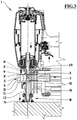
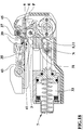
- reference 1 indicates the nailer device for collated nails S, object of the present invention.
- the collated nails S also indicated as band or strip of nails, includes an elongated strip E with a nearly flat surface and equipped with at least a plurality of first connections P which stick out from it and each one is equipped with a fixing end F opposite to the end of the first connection and which is fixed to the remaining part of the elongated strip E and which is assigned to the removable fixing of a respective nail N.
- the elongated strip E of the collated nails S is also equipped with a plurality of second connections D each one parallel, spaced and facing a corresponding first connection P with which it cooperates to the removable fixing of a same nail N.
- Each second connection D in equipped with a respective fixing end G, opposite to the remaining part of the elongated strip E and assigned to the removable fixing of the same nail N of the corresponding first connection P.
- the first connections P are fixed to the longitudinal edge of the elongated strip E nearest to the thrusting means in the internal extreme condition and the second connections D are fixed to the opposite longitudinal edge of the elongated strip E that is the nearest edge to the exit end, or muzzle, of the nail outlet duct 11.
- the fixing ends F, G of such connections P, D has respective circumferential arc recesses each one subtending to an angle exceeding 180° and which has radius equal or lightly lower to the radius of the stem of the nail which they have to block in a removable way.
- Portions between two consecutive nails and one end of the elongated strip E could be equipped with respective windows or openings assigned to an arrest tooth which will be described below.
- the elongated strip E of the collated nails S is preferably made integral with the connection first P and second D and is preferably made of plastic material; such plastic material, generally has a certain degree of resilience which it keeps, at least partially, also after a plastic deformation.
- Device 1 includes at least one magazine 3 for example consisting in one concave guide for example rectilinear, with an elongated C-shaped section, accessible and completed by a door 43 that is hinged to the device by means of a pivot pin 45.
- Such magazine 3 is assigned to receive, through the door 43, at least one collated nails, and it 3 flows into a shot chamber 5.
- Said magazine 3 is equipped with a feeding mechanism 7 to feed the shot chamber 5 with a nail N at a time.
- Device 1 also includes a sliding seat 9 aligned to the magazine 3 and communicating with the shot chamber 5 from which it receives, step by step the nails are fired, the elongated strip E which brings up to a respective exit for the elongated strip itself.
- Device 1 also includes a nail outlet duct 11 aligned to the shot chamber 5 from which it receives a nail N pushed by an operative head of a thrusting means 13 aligned to the shot chamber and to the nail outlet duct 11.
- the thrusting means 13 is axially shifted, with a reciprocating motion, by a linear actuator, for example of pneumatic type. During the stroke of such thrusting means 13 between its internal extreme condition I and its external extreme condition B. through the shot chamber 5 and such outlet duct 11, the operative head of the thrusting means 13 expels and fixes the nail N, or rather it shoots it.
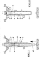
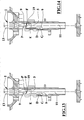
- the thrusting means 13 is equipped with a matching means 15 assigned to match with the fixing end F of the first connection P which brings the fired nail in the stroke of the thrusting means 13 from its external extreme condition to its internal extreme condition to align such first connection P to the respective portion of the sliding seat.
- the matching means 15 is placed between the positions took in such condition by the fixing ends F, G of the connection first P and second D of the fired nail.
- the distance of the matching means 15 from the operative head of the thrusting means is determined according to the dimension of the element of the collated nails and the device so that when the operative head of the thrusting means 13 reaches its lower dead centre referred to the orientation of the device in figure 1 the matching means 15 goes over the fixing end F of the first connection P but does not reach the fixing end G of the second connection D placing itself between such fixing ends F, G.
- the thrusting means 13 consist of a stem or a beam prismatic or preferably cylindrical shaped, for example made of steel, and the matching means 15 consist of a shoulder, for example ring-shaped, carried out in the material of the thrusting means 13, or rather inside the prismatic or cylindrical profile of the thrusting means, and oriented in a direction opposite to the exit for the nail N of the nail outlet duct 11.
- a superficial segment of the thrusting means 13, starting from the matching means 15 and extending in a direction opposite to the exit for the nail N of the nail outlet duct 11 is tapered and/or bevelled.
- the shoulder and the tapered segment of the matching means can be obtained by removal of material of the thrusting means 13 cylindrical or prismatic by means of turning or milling.
- the portion of the sliding seat 9 which flows into the shot chamber 5 has a chamfered means 19 with inclined planes or curved surfaces fillet the shot chamber 5 with the sliding seat 9, and said chamfered means 19 being assigned to guide the entrance of the first connections P in the sliding seat 9.
- the feeding mechanism 7 includes a driving pawl means 31 activated by reciprocating motion by a linear actuator 33, for example of a pneumatic type, said driving pawl means 31 acting on at least one nail N of the collated nails S.
- the feeding mechanism 7 includes a non-return pawl means 35 acting on the elongated strip E by means of its arrest tooth which can be engaged in such windows of the elongated strip E.
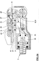
- Device 1 includes also an elastic pushing means 37 sticking out into the lumen of the magazine 3 and assigned to exert a force on the elongated strip E of the collated nails S at least partially oriented towards the shot chamber 5.
- Such elastic pushing means 37 is assigned, on the one hand, to collaborate with the arrest tooth of the feeding mechanism 7 , on the other hand to bring the last nail in the shot chamber and finally to stabilize the position of the collated nails and in particular of the nail in the shot chamber, contributing to the right bending and entering the first means of connection P by means of the matching means 15.
- the feeding mechanism 7 described is not sufficient to place correctly the last nail in the shot chamber.
- the device includes also a locking means 39, for example consisting of fixed rise or beating match, assigned to stop the stroke of the elastic pushing means 37, stopping its thrust onto the elongated strip E when the last nail has been pushed and accurately placed by the elastic pushing means 37 itself in the shot chamber.
- a locking means 39 for example consisting of fixed rise or beating match, assigned to stop the stroke of the elastic pushing means 37, stopping its thrust onto the elongated strip E when the last nail has been pushed and accurately placed by the elastic pushing means 37 itself in the shot chamber.
- the elastic pushing means 37 includes a torsion helicoidal spring means which one operative end 41 acts on a longitudinal face of the elongated strip E and onto the rear end of the latter in correspondence oh the last nail N.
- the magazine 3 is equipped with a door 43 hinged around its own pivot pin 45 connected to the device, said 43 can be opened to insert in the magazine itself at least one collated nails S.
- the lumen of the helicoid of the torsion helicoidal spring means is engaged by the pivot pin 45 around which the operative end 41 of the elastic pushing means 37 rotates.
- the non-return pawl means 35 is housed in the door 43 and its sticking out arrest tooth is placed at a distance from the operative end 41 of the elastic pushing means 37 ranging from one third and five thirds of the distance between two nails N which are adjacent in the collated nails S.
- the operation of the device provides that the thrusting means 13 in its nail shot stroke bends both of the connections first P and second D towards the muzzle and that the matching means 15 during the return stroke of the thrusting means 13 hooks and bends towards the direction opposite to the muzzle the first connection P, allowing it to slide towards and along the sliding seat 9 without binds or blockages.
- the elastic pushing means 37 contributes to avoid binds and allows to shoot also the last nail, which otherwise would be wasted.
Landscapes
- Engineering & Computer Science (AREA)
- Mechanical Engineering (AREA)
- Chemical & Material Sciences (AREA)
- Combustion & Propulsion (AREA)
- Portable Nailing Machines And Staplers (AREA)
Claims (10)
- Dispositif de clouage pour clous assemblés (S) comprenant une bande allongée (E) de forme presque plate et ayant au moins une pluralité de premières liaisons (P) se projetant à partir de celle-ci et comprenant chacune une extrémité de fixation (F) opposée à la bande allongée (E) et destinée à la fixation amovible d'un clou respectif (N) ; ledit dispositif (1) comprend au moins un magasin (3) pour au moins un clou assemblé, ledit magasin (3) mène à une chambre de tir (5) et il (3) comprend un mécanisme d'acheminement (7) pour fournir à la chambre de tir (5) un clou (N) pendant une certaine durée ; un siège coulissant (9) aligné avec le magasin (3) et en communication avec la chambre de tir (5) à partir de laquelle il (9) reçoit la bande allongée (E) qu'il (9) avance jusqu'à une sortie respective pour la bande allongée ; un conduit de sortie (11), pour le clou, aligné avec la chambre des tir (5) à partir de laquelle il (11) reçoit un clou (N) poussé par un moyen de poussée (13), aligné avec le conduit de sortie (11), pendant la course dudit moyen de poussée (13) entre son état extrême interne (I) et son état extrême externe (B), à travers la chambre de tir (5) et ledit conduit de sortie (11) pour éjecter et fixer le clou (N) ; ledit dispositif étant caractérisé par le fait que le moyen de poussée (13) comprend un moyen d'association (15) destiné à être associé à l'extrémité de fixation (F) de la première liaison (P) portant précédemment le clou tiré pendant la course du moyen de poussée (13) de son état extrême externe à son état extrême interne pour aligner la première liaison (P) de ladite extrémité de fixation (F) avec la partie respective du siège coulissant.
- Dispositif selon la revendication 1, caractérisé par le fait que, dans le cas où la bande allongée (E) comprend une pluralité de secondes liaisons (D) faisant chacune face à une première liaison correspondante (P) avec laquelle elle coopère pour la fixation amovible du même clou (N), chaque seconde liaison ayant une extrémité de fixation respective (G) pour le clou (N), les premières liaisons (P) étant fixées au bord longitudinal de la bande allongée (E) plus près du moyen de poussée dans l'état extrême interne et les secondes liaisons (D) étant fixées au bord longitudinal opposé de la bande allongée (E) qui est plus proche de l'extrémité de sortie du conduit de sortie pour le clou (11), dans l'état extrême externe du moyen de poussée (13), le moyen d'association (15) est placé entre les positions adoptées dans cet état par les extrémités de fixation (F, G) des premières (P) et secondes (D) liaisons du clou qui a été tiré.
- Dispositif selon la revendication 1 ou 2, caractérisé par le fait que le moyen de poussée (13) consiste en une tige ou barre prismatique ou cylindrique, et que le moyen d'association (15) consiste en un épaulement réalisé dans le matériau du moyen de poussée (13) et dirigé dans la direction opposée par rapport à la sortie pour le clou (N) du conduit de sortie pour le clou (11) .
- Dispositif selon la revendication 3, caractérisé par le fait qu'une partie de surface du moyen de poussée (13) commençant à partir du moyen d'association (15) et dans la direction opposée par rapport à la sortie pour le clou (N) du conduit de sortie (11) est effilée et/ou lissée.
- Dispositif selon l'une quelconque des revendications précédentes, caractérisé par le fait que la partie du siège coulissant (9) menant à la chambre de tir (5) a un moyen chanfreiné de surfaces incurvées ou de plans inclinés (19) reliant la chambre de tir (5) au siège coulissant (9) et destiné à entraîner l'entrée au moins des premières liaisons (P) dans le siège coulissant (9).
- Dispositif selon l'une quelconque des revendications précédentes, caractérisé par le fait que le mécanisme d'acheminement (7) comprend un moyen de cliquet d'entraînement (31) actionné suivant un mouvement de va-et-vient par un actionneur (3) et agissant sur un clou (N) des clous assemblés (S) et il (7) comprend un moyen de cliquet de non-retour (35) agissant sur la bande allongée (E).
- Dispositif selon l'une quelconque des revendications précédentes, caractérisé par le fait qu'il comprend un moyen de poussée élastique (37) se projetant dans la cavité du magasin (3) et destiné à exercer une force sur la bande allongée (E) des clous assemblés (S) au moins partiellement dirigée vers la chambre de tir (5), et il (1) comprend un moyen de verrouillage (39) destiné à verrouiller la poussée du moyen de poussée élastique (37) sur la bande allongée (E) lorsque le dernier clou a été poussé par le moyen de poussée élastique (37) dans la chambre de tir.
- Dispositif selon la revendication 7, caractérisé par le fait que le moyen de poussée élastique (37) comprend un moyen de ressort de torsion hélicoïdal dont une extrémité fonctionnelle (41) agit sur une face longitudinale de la bande allongée (E) et sur l'extrémité arrière de cette dernière en correspondance avec le dernier clou (N).
- Dispositif selon l'une quelconque des revendications 1 à 5 ou 7 et selon les revendications 6 et 8, caractérisé par le fait que le magasin (3) comprend une porte (43) articulée autour d'un axe de pivot (45) et apte à s'ouvrir pour l'insertion, dans le magasin lui-même, d'au moins un clou assemblé (S) ; la cavité de l'hélice du moyen de ressort de torsion hélicoïdal est engagée par l'axe de pivot (45).
- Dispositif selon la revendication 9, caractérisé par le fait que le moyen de cliquet de non-retour (35) est reçu dans la porte (43) et sa dent en saillie est placée à une distance de l'extrémité fonctionnelle (41) du moyen de poussée élastique (37) allant d'un tiers à cinq tiers de la distance entre deux clous adjacents (N) des clous assemblés (S).
Applications Claiming Priority (1)
| Application Number | Priority Date | Filing Date | Title |
|---|---|---|---|
| ITUB2015A009529A ITUB20159529A1 (it) | 2015-12-24 | 2015-12-24 | Dispositivo a chiodatrice per chiodi in stecca |
Publications (2)
| Publication Number | Publication Date |
|---|---|
| EP3184246A1 EP3184246A1 (fr) | 2017-06-28 |
| EP3184246B1 true EP3184246B1 (fr) | 2018-10-03 |
Family
ID=55697398
Family Applications (1)
| Application Number | Title | Priority Date | Filing Date |
|---|---|---|---|
| EP16205174.2A Active EP3184246B1 (fr) | 2015-12-24 | 2016-12-19 | Dispositif de clouage de clous assemblés |
Country Status (4)
| Country | Link |
|---|---|
| US (1) | US10589408B2 (fr) |
| EP (1) | EP3184246B1 (fr) |
| DK (1) | DK3184246T3 (fr) |
| IT (1) | ITUB20159529A1 (fr) |
Families Citing this family (2)
| Publication number | Priority date | Publication date | Assignee | Title |
|---|---|---|---|---|
| EP4289578B1 (fr) * | 2022-05-20 | 2026-01-21 | Illinois Tool Works Inc. | Coupe-bande |
| JP2024061316A (ja) * | 2022-10-21 | 2024-05-07 | マックス株式会社 | 手持ち工具 |
Family Cites Families (10)
| Publication number | Priority date | Publication date | Assignee | Title |
|---|---|---|---|---|
| NO116033B (fr) * | 1966-09-27 | 1969-01-13 | Gunnebo Bruks Ab | |
| US3623646A (en) * | 1969-12-15 | 1971-11-30 | Reich Maschf Gmbh Karl | Fastener-inserting machine |
| US4072261A (en) * | 1974-07-22 | 1978-02-07 | Intertack Anstalt | Pistol apparatus for driving tacks, nails and the like into material |
| JPH07100208B2 (ja) * | 1992-10-15 | 1995-11-01 | 大内 正年 | ブラインドリベット保持体 |
| JPH08300273A (ja) * | 1995-04-28 | 1996-11-19 | Max Co Ltd | 連結釘用釘打機における連結釘の案内機構 |
| JP3520754B2 (ja) * | 1997-12-19 | 2004-04-19 | 日立工機株式会社 | 打込機 |
| IT1299814B1 (it) * | 1998-01-09 | 2000-04-04 | Fasco Spa | Fissatrice ad aria compressa. |
| JP4399992B2 (ja) * | 2001-02-15 | 2010-01-20 | マックス株式会社 | 釘打機における連結釘供給機構 |
| US6708821B2 (en) * | 2002-08-21 | 2004-03-23 | Illinois Tool Works Inc. | Fastener collation strip and debris exhaust mechanism |
| DE102007000025A1 (de) * | 2007-01-19 | 2008-08-28 | Hilti Ag | Handgeführtes Setzgerät |
-
2015
- 2015-12-24 IT ITUB2015A009529A patent/ITUB20159529A1/it unknown
-
2016
- 2016-12-19 EP EP16205174.2A patent/EP3184246B1/fr active Active
- 2016-12-19 DK DK16205174.2T patent/DK3184246T3/en active
- 2016-12-23 US US15/390,213 patent/US10589408B2/en active Active
Non-Patent Citations (1)
| Title |
|---|
| None * |
Also Published As
| Publication number | Publication date |
|---|---|
| US20170182644A1 (en) | 2017-06-29 |
| EP3184246A1 (fr) | 2017-06-28 |
| ITUB20159529A1 (it) | 2017-06-24 |
| DK3184246T3 (en) | 2018-12-17 |
| US10589408B2 (en) | 2020-03-17 |
Similar Documents
| Publication | Publication Date | Title |
|---|---|---|
| US4804127A (en) | Fastener driving gun | |
| EP3774182B1 (fr) | Mécanisme de poussée destiné à un dispositif d'entraînement d'éléments de fixation motorisé | |
| EP1454716B1 (fr) | Pistolet pneumatique pour l'implantation d'éléments de fixation | |
| CN105555207B (zh) | 一种外科夹具施夹器 | |
| EP3065913B1 (fr) | Outil d'entraînement de dispositifs de fixation ayant un élément de guidage à chambre de nez automatique | |
| US6779701B2 (en) | Appliance for storing, distributing and placing couched I-shaped surgical fasteners | |
| US4442965A (en) | Nail feed mechanism | |
| ES2286216T3 (es) | Mecanismo seguro para herramienta impulsora de fiadoras. | |
| CN106456185B (zh) | 具有保持导轨上的支撑板/桥的医疗轴杆器械 | |
| US9586311B2 (en) | Fastening tool assembly | |
| EP3184246B1 (fr) | Dispositif de clouage de clous assemblés | |
| CN102039580B (zh) | 紧固件打入机 | |
| IE41492B1 (en) | Explosive-powered fastener-driving tool | |
| US4162033A (en) | Powder actuated tool | |
| CA3002830C (fr) | Magasin destine a un outil de fixation | |
| US7757921B2 (en) | Driving machine | |
| TWI590928B (zh) | Link the nail into the machine | |
| US5005750A (en) | Magazine for compressed-air riveting guns | |
| US4768696A (en) | Arrangement in nail driving apparatus | |
| US20200376639A1 (en) | Multiple strike fastener driver/holder | |
| CN215903451U (zh) | 一种射钉枪辅助装置 | |
| JP5459097B2 (ja) | ファスナー打込み機 | |
| EP4537985A2 (fr) | Guide de fixation de magasin pour outil d'entraînement de fixation | |
| US20040182908A1 (en) | Power tool for metal piercing fasteners | |
| NZ742160B (en) | Magazine for a fastener tool |
Legal Events
| Date | Code | Title | Description |
|---|---|---|---|
| PUAI | Public reference made under article 153(3) epc to a published international application that has entered the european phase |
Free format text: ORIGINAL CODE: 0009012 |
|
| AK | Designated contracting states |
Kind code of ref document: A1 Designated state(s): AL AT BE BG CH CY CZ DE DK EE ES FI FR GB GR HR HU IE IS IT LI LT LU LV MC MK MT NL NO PL PT RO RS SE SI SK SM TR |
|
| AX | Request for extension of the european patent |
Extension state: BA ME |
|
| 17P | Request for examination filed |
Effective date: 20171215 |
|
| RBV | Designated contracting states (corrected) |
Designated state(s): AL AT BE BG CH CY CZ DE DK EE ES FI FR GB GR HR HU IE IS IT LI LT LU LV MC MK MT NL NO PL PT RO RS SE SI SK SM TR |
|
| GRAP | Despatch of communication of intention to grant a patent |
Free format text: ORIGINAL CODE: EPIDOSNIGR1 |
|
| RIC1 | Information provided on ipc code assigned before grant |
Ipc: B25C 1/18 20060101ALI20180426BHEP Ipc: B25C 1/00 20060101AFI20180426BHEP |
|
| INTG | Intention to grant announced |
Effective date: 20180518 |
|
| GRAS | Grant fee paid |
Free format text: ORIGINAL CODE: EPIDOSNIGR3 |
|
| GRAA | (expected) grant |
Free format text: ORIGINAL CODE: 0009210 |
|
| RIN1 | Information on inventor provided before grant (corrected) |
Inventor name: CARATI, ANDREA |
|
| AK | Designated contracting states |
Kind code of ref document: B1 Designated state(s): AL AT BE BG CH CY CZ DE DK EE ES FI FR GB GR HR HU IE IS IT LI LT LU LV MC MK MT NL NO PL PT RO RS SE SI SK SM TR |
|
| REG | Reference to a national code |
Ref country code: GB Ref legal event code: FG4D |
|
| REG | Reference to a national code |
Ref country code: CH Ref legal event code: EP Ref country code: AT Ref legal event code: REF Ref document number: 1048106 Country of ref document: AT Kind code of ref document: T Effective date: 20181015 |
|
| REG | Reference to a national code |
Ref country code: IE Ref legal event code: FG4D Ref country code: DE Ref legal event code: R096 Ref document number: 602016006222 Country of ref document: DE |
|
| REG | Reference to a national code |
Ref country code: DK Ref legal event code: T3 Effective date: 20181210 |
|
| REG | Reference to a national code |
Ref country code: SE Ref legal event code: TRGR |
|
| REG | Reference to a national code |
Ref country code: NL Ref legal event code: MP Effective date: 20181003 |
|
| REG | Reference to a national code |
Ref country code: NO Ref legal event code: T2 Effective date: 20181003 |
|
| REG | Reference to a national code |
Ref country code: LT Ref legal event code: MG4D |
|
| PG25 | Lapsed in a contracting state [announced via postgrant information from national office to epo] |
Ref country code: NL Free format text: LAPSE BECAUSE OF FAILURE TO SUBMIT A TRANSLATION OF THE DESCRIPTION OR TO PAY THE FEE WITHIN THE PRESCRIBED TIME-LIMIT Effective date: 20181003 |
|
| PG25 | Lapsed in a contracting state [announced via postgrant information from national office to epo] |
Ref country code: BG Free format text: LAPSE BECAUSE OF FAILURE TO SUBMIT A TRANSLATION OF THE DESCRIPTION OR TO PAY THE FEE WITHIN THE PRESCRIBED TIME-LIMIT Effective date: 20190103 Ref country code: IS Free format text: LAPSE BECAUSE OF FAILURE TO SUBMIT A TRANSLATION OF THE DESCRIPTION OR TO PAY THE FEE WITHIN THE PRESCRIBED TIME-LIMIT Effective date: 20190203 Ref country code: LT Free format text: LAPSE BECAUSE OF FAILURE TO SUBMIT A TRANSLATION OF THE DESCRIPTION OR TO PAY THE FEE WITHIN THE PRESCRIBED TIME-LIMIT Effective date: 20181003 Ref country code: FI Free format text: LAPSE BECAUSE OF FAILURE TO SUBMIT A TRANSLATION OF THE DESCRIPTION OR TO PAY THE FEE WITHIN THE PRESCRIBED TIME-LIMIT Effective date: 20181003 Ref country code: LV Free format text: LAPSE BECAUSE OF FAILURE TO SUBMIT A TRANSLATION OF THE DESCRIPTION OR TO PAY THE FEE WITHIN THE PRESCRIBED TIME-LIMIT Effective date: 20181003 Ref country code: HR Free format text: LAPSE BECAUSE OF FAILURE TO SUBMIT A TRANSLATION OF THE DESCRIPTION OR TO PAY THE FEE WITHIN THE PRESCRIBED TIME-LIMIT Effective date: 20181003 Ref country code: PL Free format text: LAPSE BECAUSE OF FAILURE TO SUBMIT A TRANSLATION OF THE DESCRIPTION OR TO PAY THE FEE WITHIN THE PRESCRIBED TIME-LIMIT Effective date: 20181003 Ref country code: ES Free format text: LAPSE BECAUSE OF FAILURE TO SUBMIT A TRANSLATION OF THE DESCRIPTION OR TO PAY THE FEE WITHIN THE PRESCRIBED TIME-LIMIT Effective date: 20181003 Ref country code: CZ Free format text: LAPSE BECAUSE OF FAILURE TO SUBMIT A TRANSLATION OF THE DESCRIPTION OR TO PAY THE FEE WITHIN THE PRESCRIBED TIME-LIMIT Effective date: 20181003 |
|
| PG25 | Lapsed in a contracting state [announced via postgrant information from national office to epo] |
Ref country code: PT Free format text: LAPSE BECAUSE OF FAILURE TO SUBMIT A TRANSLATION OF THE DESCRIPTION OR TO PAY THE FEE WITHIN THE PRESCRIBED TIME-LIMIT Effective date: 20190203 Ref country code: GR Free format text: LAPSE BECAUSE OF FAILURE TO SUBMIT A TRANSLATION OF THE DESCRIPTION OR TO PAY THE FEE WITHIN THE PRESCRIBED TIME-LIMIT Effective date: 20190104 Ref country code: RS Free format text: LAPSE BECAUSE OF FAILURE TO SUBMIT A TRANSLATION OF THE DESCRIPTION OR TO PAY THE FEE WITHIN THE PRESCRIBED TIME-LIMIT Effective date: 20181003 Ref country code: AL Free format text: LAPSE BECAUSE OF FAILURE TO SUBMIT A TRANSLATION OF THE DESCRIPTION OR TO PAY THE FEE WITHIN THE PRESCRIBED TIME-LIMIT Effective date: 20181003 |
|
| REG | Reference to a national code |
Ref country code: DE Ref legal event code: R097 Ref document number: 602016006222 Country of ref document: DE |
|
| PG25 | Lapsed in a contracting state [announced via postgrant information from national office to epo] |
Ref country code: IT Free format text: LAPSE BECAUSE OF FAILURE TO SUBMIT A TRANSLATION OF THE DESCRIPTION OR TO PAY THE FEE WITHIN THE PRESCRIBED TIME-LIMIT Effective date: 20181003 |
|
| PLBE | No opposition filed within time limit |
Free format text: ORIGINAL CODE: 0009261 |
|
| STAA | Information on the status of an ep patent application or granted ep patent |
Free format text: STATUS: NO OPPOSITION FILED WITHIN TIME LIMIT |
|
| PG25 | Lapsed in a contracting state [announced via postgrant information from national office to epo] |
Ref country code: SK Free format text: LAPSE BECAUSE OF FAILURE TO SUBMIT A TRANSLATION OF THE DESCRIPTION OR TO PAY THE FEE WITHIN THE PRESCRIBED TIME-LIMIT Effective date: 20181003 Ref country code: MC Free format text: LAPSE BECAUSE OF FAILURE TO SUBMIT A TRANSLATION OF THE DESCRIPTION OR TO PAY THE FEE WITHIN THE PRESCRIBED TIME-LIMIT Effective date: 20181003 Ref country code: EE Free format text: LAPSE BECAUSE OF FAILURE TO SUBMIT A TRANSLATION OF THE DESCRIPTION OR TO PAY THE FEE WITHIN THE PRESCRIBED TIME-LIMIT Effective date: 20181003 Ref country code: LU Free format text: LAPSE BECAUSE OF NON-PAYMENT OF DUE FEES Effective date: 20181219 Ref country code: SM Free format text: LAPSE BECAUSE OF FAILURE TO SUBMIT A TRANSLATION OF THE DESCRIPTION OR TO PAY THE FEE WITHIN THE PRESCRIBED TIME-LIMIT Effective date: 20181003 Ref country code: RO Free format text: LAPSE BECAUSE OF FAILURE TO SUBMIT A TRANSLATION OF THE DESCRIPTION OR TO PAY THE FEE WITHIN THE PRESCRIBED TIME-LIMIT Effective date: 20181003 |
|
| 26N | No opposition filed |
Effective date: 20190704 |
|
| REG | Reference to a national code |
Ref country code: IE Ref legal event code: MM4A |
|
| REG | Reference to a national code |
Ref country code: BE Ref legal event code: MM Effective date: 20181231 |
|
| PG25 | Lapsed in a contracting state [announced via postgrant information from national office to epo] |
Ref country code: IE Free format text: LAPSE BECAUSE OF NON-PAYMENT OF DUE FEES Effective date: 20181219 Ref country code: SI Free format text: LAPSE BECAUSE OF FAILURE TO SUBMIT A TRANSLATION OF THE DESCRIPTION OR TO PAY THE FEE WITHIN THE PRESCRIBED TIME-LIMIT Effective date: 20181003 |
|
| PG25 | Lapsed in a contracting state [announced via postgrant information from national office to epo] |
Ref country code: BE Free format text: LAPSE BECAUSE OF NON-PAYMENT OF DUE FEES Effective date: 20181231 |
|
| PG25 | Lapsed in a contracting state [announced via postgrant information from national office to epo] |
Ref country code: MT Free format text: LAPSE BECAUSE OF NON-PAYMENT OF DUE FEES Effective date: 20181219 |
|
| PG25 | Lapsed in a contracting state [announced via postgrant information from national office to epo] |
Ref country code: TR Free format text: LAPSE BECAUSE OF FAILURE TO SUBMIT A TRANSLATION OF THE DESCRIPTION OR TO PAY THE FEE WITHIN THE PRESCRIBED TIME-LIMIT Effective date: 20181003 |
|
| PG25 | Lapsed in a contracting state [announced via postgrant information from national office to epo] |
Ref country code: HU Free format text: LAPSE BECAUSE OF FAILURE TO SUBMIT A TRANSLATION OF THE DESCRIPTION OR TO PAY THE FEE WITHIN THE PRESCRIBED TIME-LIMIT; INVALID AB INITIO Effective date: 20161219 Ref country code: MK Free format text: LAPSE BECAUSE OF NON-PAYMENT OF DUE FEES Effective date: 20181003 Ref country code: CY Free format text: LAPSE BECAUSE OF FAILURE TO SUBMIT A TRANSLATION OF THE DESCRIPTION OR TO PAY THE FEE WITHIN THE PRESCRIBED TIME-LIMIT Effective date: 20181003 |
|
| REG | Reference to a national code |
Ref country code: CH Ref legal event code: PL |
|
| PG25 | Lapsed in a contracting state [announced via postgrant information from national office to epo] |
Ref country code: LI Free format text: LAPSE BECAUSE OF NON-PAYMENT OF DUE FEES Effective date: 20191231 Ref country code: CH Free format text: LAPSE BECAUSE OF NON-PAYMENT OF DUE FEES Effective date: 20191231 |
|
| REG | Reference to a national code |
Ref country code: AT Ref legal event code: UEP Ref document number: 1048106 Country of ref document: AT Kind code of ref document: T Effective date: 20181003 |
|
| REG | Reference to a national code |
Ref country code: DE Ref legal event code: R081 Ref document number: 602016006222 Country of ref document: DE Owner name: FASCO. S.R.L., CASTEL MAGGIORE, IT Free format text: FORMER OWNER: FASCO S.R.L., GRANAROLO DELL'EMILIA, BO, IT |
|
| PGFP | Annual fee paid to national office [announced via postgrant information from national office to epo] |
Ref country code: NO Payment date: 20241219 Year of fee payment: 9 |
|
| PGFP | Annual fee paid to national office [announced via postgrant information from national office to epo] |
Ref country code: DK Payment date: 20241224 Year of fee payment: 9 |
|
| PGFP | Annual fee paid to national office [announced via postgrant information from national office to epo] |
Ref country code: GB Payment date: 20241218 Year of fee payment: 9 |
|
| PGFP | Annual fee paid to national office [announced via postgrant information from national office to epo] |
Ref country code: FR Payment date: 20241227 Year of fee payment: 9 |
|
| PGFP | Annual fee paid to national office [announced via postgrant information from national office to epo] |
Ref country code: AT Payment date: 20241218 Year of fee payment: 9 |
|
| PGFP | Annual fee paid to national office [announced via postgrant information from national office to epo] |
Ref country code: SE Payment date: 20241224 Year of fee payment: 9 |
|
| PGFP | Annual fee paid to national office [announced via postgrant information from national office to epo] |
Ref country code: DE Payment date: 20241227 Year of fee payment: 9 |