EP3774182B1 - Mécanisme de poussée destiné à un dispositif d'entraînement d'éléments de fixation motorisé - Google Patents
Mécanisme de poussée destiné à un dispositif d'entraînement d'éléments de fixation motorisé Download PDFInfo
- Publication number
- EP3774182B1 EP3774182B1 EP19785818.6A EP19785818A EP3774182B1 EP 3774182 B1 EP3774182 B1 EP 3774182B1 EP 19785818 A EP19785818 A EP 19785818A EP 3774182 B1 EP3774182 B1 EP 3774182B1
- Authority
- EP
- European Patent Office
- Prior art keywords
- nosepiece
- driver
- coupled
- lever
- cam
- Prior art date
- Legal status (The legal status is an assumption and is not a legal conclusion. Google has not performed a legal analysis and makes no representation as to the accuracy of the status listed.)
- Active
Links
Images


Classifications
-
- B—PERFORMING OPERATIONS; TRANSPORTING
- B25—HAND TOOLS; PORTABLE POWER-DRIVEN TOOLS; MANIPULATORS
- B25C—HAND-HELD NAILING OR STAPLING TOOLS; MANUALLY OPERATED PORTABLE STAPLING TOOLS
- B25C1/00—Hand-held nailing tools; Nail feeding devices
- B25C1/04—Hand-held nailing tools; Nail feeding devices operated by fluid pressure, e.g. by air pressure
- B25C1/047—Mechanical details
-
- B—PERFORMING OPERATIONS; TRANSPORTING
- B25—HAND TOOLS; PORTABLE POWER-DRIVEN TOOLS; MANIPULATORS
- B25C—HAND-HELD NAILING OR STAPLING TOOLS; MANUALLY OPERATED PORTABLE STAPLING TOOLS
- B25C1/00—Hand-held nailing tools; Nail feeding devices
- B25C1/001—Nail feeding devices
- B25C1/003—Nail feeding devices for belts of nails
-
- B—PERFORMING OPERATIONS; TRANSPORTING
- B25—HAND TOOLS; PORTABLE POWER-DRIVEN TOOLS; MANIPULATORS
- B25C—HAND-HELD NAILING OR STAPLING TOOLS; MANUALLY OPERATED PORTABLE STAPLING TOOLS
- B25C1/00—Hand-held nailing tools; Nail feeding devices
- B25C1/06—Hand-held nailing tools; Nail feeding devices operated by electric power
Definitions
- the present invention relates to powered fastener drivers, and more specifically to pusher mechanisms for powered fastener drivers.
- Powered fastener drivers are used for driving fasteners (e.g., nails, tacks, staples, etc.) into a workpiece.
- fastener drivers typically include a magazine in which the fasteners are stored and a pusher mechanism for individually transferring fasteners from the magazine to a fastener driving channel, where the fastener is impacted by a driver blade during a fastener driving operation.
- US 2017/361444 A1 describes a fastener driver that includes a drive blade movable from a retracted position to a driven position for driving a fastener into a workpiece and a gas spring mechanism for driving the drive blade from the retracted position to the driven position.
- the gas spring mechanism includes a piston movable between a retracted position and a driven position.
- the fastener driver further includes a first return mechanism for moving the drive blade from the driven position toward the retracted position, and a second return mechanism for moving the piston from the driven position toward the retracted position.
- US 5 570 618 A relates to an advance and release mechanism for strips of a screwdriver assembly that sequentially drives fasteners retained in a holding strip securing a plurality of fasteners in a row.
- the apparatus has a slide body with a lateral slot and an intersecting vertical bore.
- the lateral slot has a uniform transverse cross-section configured to slidingly receive the strip.
- a driver shaft including fastener driving bit means for engaging and driving a lead fastener in succession into said work piece is journalled and longitudinally slidably housed in the bore between an engaged position and a withdrawn position.
- Advance means are mounted to the body for incrementally forwardly advancing the fasteners of the strip within the lateral slot in succession and for aligning the lead fastener coaxially with the bore.
- the advance means includes: a shuttle housed in the body and reciprocally movable between an advanced position and retracted position; a pawl pivotably supported on the shuttle, the pawl having a strip pusher arm at a forward end thereof; pawl biasing means engaging the pawl and shuttle for urging the pusher arm into parallel engagement with the strip; and pawl release means engaging the pawl for manually disengaging the pawl from the strip, thereby permitting the screw strip to be removed from the lateral slot.
- US 2006/186171 A1 describes fastener-advancement systems that comprise a multiple lever and linkage mechanically operated system operatively connected to the driver blade member of the fastener driving tool, as well as electromechanically operated systems, for advancing a leading fastener of a collated strip of fasteners into the driver blade channel of the fastener-driving tool.
- electromechanically operated systems push-type, pull-type, and rotary solenoid actuating members are utilized for moving the fastener-advancement feed pawl or claw member.
- a powered fastener driver including a housing, a nosepiece coupled to the housing and extending therefrom, a driver blade, a canister magazine coupled to the nosepiece, a pusher mechanism coupled to the nosepiece, and a cam.
- the driver blade is movable within the nosepiece between a ready position and a driven position.
- the nosepiece receives collated fasteners therein.
- the pusher mechanism individually transfers collated fasteners in the canister magazine to a driver channel in the nosepiece in which the driver blade is movable.
- the pusher mechanism includes a body coupled to the nosepiece, a feeder arm pivotably coupled to the body for movement therewith, and a lever pivotably coupled to the nosepiece about a pivot axis. The body relatively translates with the nosepiece.
- the lever has a first end that is engageable with the body for imparting reciprocating translation to the body relative to the nosepiece in response to pivoting movement of the lever in opposite directions about the pivot axis.
- the cam is engaged with a second end of the lever for imparting pivoting movement to the lever.
- the feeder arm is engageable with individual fasteners in the nosepiece for sequentially pushing the fasteners into the driver channel in response to reciprocation of the body relative to the nosepiece.
- a powered fastener driver including a housing, a motor positioned in the housing, a nosepiece coupled to the housing and extending therefrom, a driver blade, a canister magazine coupled to the nosepiece, a lifting mechanism positioned within the housing, a pusher mechanism coupled to the nosepiece, a cam, and a gear train.
- the driver blade is movable within the nosepiece between a ready position and a driven position.
- the nosepiece receives collated fasteners from the canister magazine.
- the lifting mechanism is operable to move the driver blade from the driven position toward the ready position.
- the pusher mechanism individually transfers collated fasteners in the canister magazine to a driver channel in the nosepiece in which the driver blade is movable.
- the pusher mechanism includes a body coupled to the nosepiece, a feeder arm pivotably coupled to the body for relative movement therewith, and a lever pivotably coupled to the nosepiece about a pivot axis.
- the body relatively translates with the nosepiece.
- the lever has a first end that is engageable with the body for translating the body relative to the nosepiece in response to pivoting movement of the lever in opposite directions about the pivot axis, and an opposite, second end.
- the cam is engages with a second end of the lever.
- the gear train is operable to receive torque from the motor and distribute torque to the lifting mechanism and the cam, causing the cam to rotate and impart pivoting movement to the lever, which translates the body of the pusher mechanism relative to the nosepiece.
- the feeder arm is engageable with individual fasteners in the nosepiece for sequentially pushing the fasteners into the driver channel in response to reciprocation of the body relative to the nosepiece.
- a powered fastener driver including a housing, a nosepiece coupled to the housing and extending therefrom, a driver blade, a canister magazine coupled to the nosepiece, and a pusher mechanism coupled to the nosepiece.
- the driver blade is movable within the nosepiece between a ready position and a driven position.
- the nosepiece receives collated fasteners from the canister magazine.
- the pusher mechanism individually transfers collated fasteners in the canister magazine to a driver channel in the nosepiece in which the driver blade is movable.
- the pusher mechanism includes a body that is slidably coupled to the nosepiece, a feeder arm pivotably coupled to the body for movement therewith, and a solenoid.
- the body relatively translates with the nosepiece.
- the solenoid includes a solenoid housing and a plunger extending therefrom. The plunger is coupled to the body for imparting reciprocating translation to the body in response to activation and deactivation of the solenoid.
- the canister includes a mount portion to which the solenoid housing is coupled.
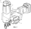
- a gas spring-powered fastener driver 10 is operable to drive fasteners (e.g., nails) held within a canister magazine 14 into a workpiece.
- the fastener driver 10 includes a housing 16, a cylinder 18 positioned within the housing 16, and a moveable piston 22 positioned within the cylinder 18.
- the fastener driver 10 further includes a driver blade 26 that is attached to the piston 22 and moveable therewith.
- the fastener driver 10 does not require an external source of air pressure, but rather includes a storage chamber cylinder 30 of pressurized gas in fluid communication with the cylinder 18. In the illustrated embodiment, the cylinder 18 and moveable piston 22 are positioned within the storage chamber cylinder 30.
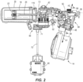
- the cylinder 18 and the driver blade 26 define a driving axis 38, and during a driving cycle the driver blade 26 and piston 22 are moveable between a ready position (i.e., top dead center) and a driven position (i.e., bottom dead center).
- the fastener driver 10 further includes a lifting mechanism 42, which is powered by a motor 46, and which is operable to move the driver blade 26 from the driven position to the ready position.
- the lifting mechanism 42 drives the piston 22 and the driver blade 26 to the ready position by energizing the motor 46.
- the gas above the piston 22 and the gas within the storage chamber cylinder 30 is compressed.
- the piston 22 and the driver blade 26 are held in position until released by user activation of a trigger 44.
- the compressed gas above the piston 22 and within the storage chamber 30 drives the piston 22 and the driver blade 26 to the driven position, thereby driving a fastener into a workpiece.
- the illustrated fastener driver 10 therefore operates on a gas spring principle utilizing the lifting assembly 42 and the piston 22 to further compress the gas within the cylinder 18 and the storage chamber cylinder 30.
- the canister magazine 14 includes collated fasteners 48 arranged in a coil.
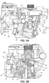
- the magazine 14 is coupled to a nosepiece 50 in which the fasteners 48 are received ( FIGS. 3-4 ).
- the fasteners 48 are sequentially transferred or loaded from the magazine 14 to a driver channel 54 in the nosepiece 50 by a pusher mechanism 58. After the fastener 48 is inserted into the driver channel 54, the driver blade 26 is movable within the driver channel 54 to discharge the fastener 48 into a workpiece.
- the pusher mechanism 58 is driven in sync with the lifting mechanism 42 by a gear train 66 coupled to a transmission output shaft 70 and a cam 62 that receives torque from the gear train 66, causing the cam 62 to rotate in unison with the lifting mechanism 42.
- the gear train 66 consists of a first gear set 71 on the nosepiece 50 are received.
- the motion of the sliding body 90 is constrained to reciprocating linear movement in the direction of arrows A1, A2 (shown in FIG. 2 ) that are parallel with the guide rails 95 relative to the magazine 14.
- the pusher mechanism 58 further includes a feeder arm 94 that is pivotably coupled to the sliding body 90 about a pivot axis 99 that is perpendicular to the direction of movement of the sliding body 90 along arrows A1, A2. Because the feeder arm 94 is supported upon the sliding body 90, the feeder arm 94 reciprocates with the sliding body 90 in the direction of arrows A1, A2 in response to reciprocating pivoting movement of the lever 74.
- a forward-most fastener 48 Prior to initiation of a firing cycle, a forward-most fastener 48 is positioned in the driver channel 54, the sliding body 90 is located in a forward-most position relative to the nosepiece 50, and the feeder arm 94 is pivoted to an inboard position to thereby receive one of the fasteners 48 behind the forward-most fastener 48 in aligned notches 98 in the feeder arm 94 ( FIGS. 4 and 5B ).
- the forward-most position of the sliding body 90 coincides with the roller 78 being in contact with a valley 104 on the cam 62 (shown in FIG. 2 ).
- check pawls 105 are pivotably coupled to a shaft 106 carried on a nosepiece access door 103, which is pivotably coupled to the nosepiece 50.
- Each check pawl 105 includes a finger 107 that is in contact with the fasteners 48.
- Springs FIG. 5B bias the respective check pawls 105 toward the fasteners 48 to maintain the fingers 107 in contact with the fasteners 48 as the fasteners 48 are advanced toward the nosepiece 50.
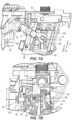
- the feeder arm 94 is retracted in the direction A1 ( FIG.
- the fingers 107 of the respective check pawls 105 remain engaged with one of the collated fasteners 48 while the feeder arm 94 pivots around the same fastener 48.
- the feeder arm 94 pivots toward an inboard position and behind the fastener 48 ( FIG. 7B ).
- the check pawls 105 are biased away from the fasteners 48 to allow the collated fasteners 48 to advance ( FIG. 8B ).
- the springs biasing the respective check pawls 105 then rebound, positioning the check pawls 105 between the next two fasteners 48 in the sequence, preventing backwards movement of the collated fasteners 48 toward the canister magazine 14 ( FIG. 6B ).
- the motor 46 is activated to rotate the lifting mechanism 42, which releases the driver blade 26, permitting the gas in the storage chamber cylinder 30 to expand and push the piston 22 downward into the cylinder 18.
- the driver blade 26 impacts the fastener 48 in the driver channel 54, discharging the fastener 48 from the nosepiece 50 and into the workpiece.
- the lifting mechanism 42 continues to rotate (i.e, by the motor 46 providing torque to the transmission output shaft 70), returning the piston 22 and driver blade 26 to the ready position in the cylinder 18. Simultaneously, the rotating transmission output shaft 70 and gear train 66 rotates the cam 62.
- the cam 62 rotates nearly 360 degrees, causing the roller 78 to follow the cam 62 as the cam surface transitions from the valley 104 to a peak 108 ( FIGS. 5A , 6A , and 7A ), imparting pivoting movement to the lever 74 about the axis 76 in a direction opposite the arrow A0 ( FIG. 2 ).
- the fork 84 pushes the protruding pin 92 of the sliding body 90, converting the pivoting motion of the lever 74 to linear motion of the body 90 ( FIG. 6A ).
- the feeder arm 94 pivots to clear the next fastener in the sequence ( FIGS. 6A and 6B ).
- the check pawls 105 remain engaged with one of the fasteners 48, preventing the collated fasteners 48 from being driven rearward toward the canister magazine 14.
- the springs biases the feeder arm 94 behind the next fastener 48 in the sequence ( FIGS. 7A and 7B ).
- continued rotation of the cam 62 causes the roller 78 to transition from the peak 108 back to the valley 104, allowing the torsion spring 77 acting on the lever 74 to rebound, pivoting the lever 74 in the direction of arrow A0 and moving the fork 84 and, thus, the body 90 forward.
- the pusher mechanism 58 may be actuated by the impact of the driver blade 26 upon reaching the driven position.
- the driver blade 26 may either directly contact or indirectly contact (e.g., via an arm or linkage, not shown) the roller 78, which imparts pivotal motion to the lever 74.
- the pivotal motion imparted on the lever 74 displaces the sliding body 90 and feeder arm 94 along arrow A2, allowing the feeder arm 94 to pick up the next fastener 48 in the collated strip.
- the pusher mechanism 58 may be actuated by the impact of the piston 22 on a bumper 110 ( FIG. 2 ) within the cylinder 18 for stopping the driver blade 26 in the driven position.
- the bumper 110 may either directly contact or indirectly contact (e.g., via an arm or linkage, not shown) the roller 78, which imparts pivotal motion to the lever 74.
- the pivotal motion imparted on the lever 74 displaces the sliding body 90 and feeder arm 94 along arrow A2, allowing the feeder arm 94 to pick up the next fastener 48 in the collated strip.
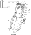
- FIG. 9 illustrates a gas spring-powered fastener driver 10A including another embodiment of a pusher mechanism 58A.
- the driver 10A is similar to the driver 10 described above with reference to FIGS. 1-8 . Accordingly, features and elements of the driver 10A corresponding with features and elements of the driver 10 are given like reference numbers followed by the letter 'A.' In addition, the following description focuses primarily on differences between the pusher mechanism 58A and the pusher mechanism 58.
- the driver 10A includes a lifting mechanism 42A that returns a piston 22A and a driver blade 26A to the ready position by energizing a motor 46A.
- the pusher mechanism 58A differs from the pusher mechanism 58 in that the pusher mechanism 58A is not driven in sync with the lifting mechanism 42A by a gear train. Rather, the pusher mechanism 58A includes a solenoid 200 ( FIG. 11 ) coupled to the canister magazine 14A via a bracket 204 clamping a solenoid housing 208 to a mount portion 212 of the canister magazine 14A.
- the bracket 204 is fastened to the mount portion 212 of the canister 14A via a plurality of fasteners 214 or the like.
- a plunger 216 is disposed within the solenoid housing 208 and is movable between an extended position and a retracted position. In the extended position, a plunger spring 220 disposed around the plunger 216 biases the plunger 216 from the solenoid housing 208. In the retracted position, the solenoid 200 is engaged, meaning an electromagnet attracts the plunger 216 within the solenoid housing 208, against the bias of the spring 220.
- a plate 224 is coupled to an end of the plunger 216 such that movement of the plunger 216 imparts reciprocating movement to the plate 224.
- the pusher mechanism 58A further includes a sliding body 90A, which has an opening 228 for receiving an end of the plate 224 to secure the body 90A to the plate 224.
- the motion of the sliding body 90A is constrained to reciprocating linear movement in the direction of arrows A1, A2 relative to the magazine 14A by engaged guide rails 232 and grooves 236.
- a feeder arm 94A is pivotably coupled to the sliding body 90A about a pivot axis 99A that is perpendicular to the direction of movement of the sliding body 90A along arrows A1, A2 and is biased toward the fasteners 48 by compression springs 244. Because the feeder arm 94A is supported upon the sliding body 90A, the feeder arm 94A reciprocates with the sliding body 90A in the direction of arrows A1, A2 in response to reciprocating movement of the plunger 216.
- the solenoid 200 is activated, retracting the plunger 216 and, thus, sliding the body 90A away from the driver channel 54A in the direction of A1, allowing the feeder arm to pivot to clear the next fastener 48 in the sequence.
- the plunger 216 is completely retracted, the body 90A is at a position farthest from the driver channel 54A, allowing the springs to bias the feeder arm behind the next fastener 48 in the sequence.
- the solenoid 200 is deactivated, causing the plunger spring 220 to bias the plunger 216 outward.
- the outward motion of the plunger 216 moves the body 90A and, in turn, the feeder arm toward the driver channel 54A.
- a forward most fastener 48 is delivered to the driver channel 54A by the feeder arm.
- the system that determines when the solenoid 200 is energized is an open feedback system, meaning the system does not know the location of the lifting mechanism 42A. Instead, once a user pulls the trigger 44, the system operates based on predetermined timing to activate and deactivate the solenoid 200.
Landscapes
- Engineering & Computer Science (AREA)
- Mechanical Engineering (AREA)
- Physics & Mathematics (AREA)
- Fluid Mechanics (AREA)
- Portable Nailing Machines And Staplers (AREA)
Claims (15)
- Appareil électroportatif à enfoncer les fixations (10), comprenant :un boîtier (16) ;un embout (50) couplé au boîtier et s'étendant à partir de celui-ci ;une lame d'avancée (26) mobile à l'intérieur de l'embout entre une position d'attente et une position d'enfoncement ;un magasin à cartouche (14) couplé à l'embout et dans lequel des éléments de fixation en rouleau (48) peuvent être reçus ;un mécanisme de levage (42) servant à déplacer la lame d'avancée de la position d'enfoncement vers la position d'attente ;un mécanisme de poussée (58) couplé à l'embout pour transférer individuellement des éléments de fixation en rouleau du magasin à cartouche vers un canal d'avancée (54) de l'embout dans lequel la lame d'avancée est mobile, caractérisé en ce que le mécanisme de poussée inclut en outre :un corps (90) couplé à l'embout en vue d'une translation relative avec celui-ci ;un bras d'alimentation (94) couplé au corps en vue d'un déplacement avec celui-ci ; etun levier (74) couplé de manière pivotante à l'embout autour d'un axe de pivotement (99), le levier comportant une première extrémité pouvant s'engager dans le corps pour conférer un mouvement de translation alternatif au corps par rapport à l'embout en réaction au déplacement par pivotement du levier dans des directions opposées autour de l'axe de pivotement ;une came (62) avec laquelle coopère une deuxième extrémité du levier pour conférer un déplacement par pivotement au levier ; etun train d'engrenages (66) pour fournir un couple au mécanisme de levage, entraînant la rotation du mécanisme de levage, dans lequel la came reçoit également un couple du train d'engrenages, entraînant la rotation de la came à l'unisson avec le mécanisme de levage ;dans lequel le bras d'alimentation peut coopérer avec les éléments de fixation individuels dans l'embout pour pousser séquentiellement les éléments de fixation dans le canal d'entraînement en réaction au mouvement alternatif du corps par rapport à l'embout.
- Appareil électroportatif à enfoncer les fixations (10) selon la revendication 1, dans lequel le levier (74) inclut une deuxième extrémité opposée à la première extrémité, et dans lequel le levier est couplé de manière pivotante à l'embout (50) autour de l'axe de pivotement (99) entre les première et deuxième extrémités du levier.
- Appareil électroportatif à enfoncer les fixations (10) selon la revendication 1, dans lequel le mécanisme de poussée (58) inclut un ressort qui sollicite le corps vers le canal d'avancée (54) de l'embout (50) ; et dans lequel le mécanisme de poussée inclut facultativement un galet (78) couplé à la deuxième extrémité du levier (74), dans lequel le ressort maintient en continu le galet en contact avec la came (62) lors de la rotation de la came.
- Appareil électroportatif à enfoncer les fixations (10) selon la revendication 1, dans lequel le corps (90) inclut un pivot (92) reçu par la première extrémité du levier (74).
- Appareil électroportatif à enfoncer les fixations (10) selon la revendication 1,dans lequel le corps (90) inclut une fente dans laquelle est reçu un rail de guidage (95) correspondant sur l'embout (50), limitant ainsi le déplacement du corps à une translation par rapport à l'embout ;
oudans lequel le bras d'alimentation (94) peut pivoter par rapport au corps autour d'un axe de pivotement (99) qui est perpendiculaire à la direction du déplacement du corps. - Appareil électroportatif à enfoncer les fixations (10) selon l'une quelconque des revendications précédentes, comprenant en outre :un moteur (46) positionné dans le boîtier ;dans lequel le mécanisme de levage (42) est positionné à l'intérieur du boîtier, etdans lequel le train d'engrenages (66) sert à recevoir le couple provenant du moteur et à distribuer le couple vers le mécanisme de levage et la came (62), entraînant la rotation de la came et imprimant un mouvement de pivotement au levier (74), qui provoque une translation du corps (90) du mécanisme de poussée par rapport à l'embout (50) .
- Appareil électroportatif à enfoncer les fixations (10) selon la revendication 6, dans lequel l'axe de pivotement (99) est situé entre les première et deuxième extrémités du levier.
- Appareil électroportatif à enfoncer les fixations (10) selon la revendication 7, dans lequel le mécanisme de poussée (58) inclut un ressort qui sollicite de corps (90) vers le canal d'avancée (54) de l'embout (50), dans lequel le mécanisme de poussée inclut un galet (78) couplé à la deuxième extrémité du levier (74), et dans lequel le ressort maintient le galet en contact continu avec la came (62) lors de la rotation de la came, et dans lequel la came inclut facultativement un creux (104) et une crête (108), et dans lequel un tour de la came, au cours duquel le galet passe du creux vers la crête pour retourner ensuite vers le creux, coïncide avec un cycle du mouvement alternatif du corps par rapport à l'embout.
- Appareil électroportatif à enfoncer les fixations (10) selon la revendication 6,dans lequel une fourche (84) est définie par la première extrémité du levier (74), et dans lequel le corps (90) inclut un pivot (92) reçu par la première extrémité du levier ;
oudans lequel le corps inclut une fente dans laquelle est reçu un rail de guidage (95) correspondant sur l'embout, limitant ainsi le déplacement du corps à une translation par rapport à l'embout. - Appareil électroportatif à enfoncer les fixations (10) selon la revendication 6, dans lequel le train d'engrenages (66) fait tourner la came (62) et le mécanisme de levage (42) de manière synchrone en réaction à une entrée de couple provenant du moteur.
- Appareil électroportatif à enfoncer les fixations (10) selon la revendication 10, comprenant en outre une transmission entre le moteur (46) et le train d'engrenages (66), dans lequel le train d'engrenages inclut un premier engrenage couplé entre l'arbre de sortie de transmission (70) et le mécanisme de levage (42) ;et dans lequel le train d'engrenages inclut facultativement un deuxième engrenage couplé entre le mécanisme de levage et la came (62) ;et plus facultativement :dans lequel les premier et deuxième engrenages sont disposés sur des côtés opposés de l'embout (50) ;
oudans lequel chacun du premier engrenage et du deuxième engrenage inclut un rapport de réduction de 1:1. - Appareil électroportatif à enfoncer les fixations (10A), comprenant :un boîtier (16) ;un embout (50) couplé au boîtier et s'étendant à partir de celui-ci ;une lame d'avancée (26A) mobile à l'intérieur de l'embout entre une position d'attente et une position d'enfoncement ;un magasin à cartouche (14A) couplé à l'embout et dans lequel des éléments de fixation en rouleau (48) peuvent être reçus ;un mécanisme de poussée (58A) couplé à l'embout pour transférer individuellement des éléments de fixation en rouleau du magasin à cartouche vers un canal d'avancée (54A) de l'embout dans lequel la lame d'avancée est mobile ; caractérisé en ce que le mécanisme de poussée inclut en outre :un corps (90A) couplé à l'embout en vue d'une translation relative avec celui-ci ;un bras d'alimentation (94A) couplé au corps en vue d'un déplacement avec celui-ci ; etun solénoïde (200) comportant un boîtier de solénoïde (208) et un piston (216) s'étendant à partir de celui-ci, le piston étant couplé au corps pour conférer un mouvement de translation alternatif au corps en réaction à l'activation et à la désactivation du solénoïde ;dans lequel le corps effectue un mouvement alternatif le long d'un premier axe, et dans lequel le piston définit un deuxième axe qui est parallèle au premier axe ; etdans lequel la cartouche inclut une partie de montage (212) à laquelle est couplé le boîtier du solénoïde.
- Appareil électroportatif à enfoncer les fixations (10A) selon la revendication 12, comprenant en outre un support (204) serrant le boîtier du solénoïde (208) sur la partie de montage (212) de la cartouche ; et dans lequel le support est facultativement fixé sur la partie de montage de la cartouche.
- Appareil électroportatif à enfoncer les fixations (10A) selon la revendication 12, dans lequel le mécanisme de poussée (58A) inclut en outre une plaque (224), et dans lequel la plaque couple le piston (216) au corps (90A) en vue d'une translation avec celui-ci.
- Appareil électroportatif à enfoncer les fixations (10A) selon la revendication 12, dans lequel le mécanisme de poussée (58A) inclut en outre un ressort (220) sollicitant le piston vers une position déployée.
Applications Claiming Priority (3)
| Application Number | Priority Date | Filing Date | Title |
|---|---|---|---|
| US201862657357P | 2018-04-13 | 2018-04-13 | |
| US201862779809P | 2018-12-14 | 2018-12-14 | |
| PCT/US2019/026043 WO2019199605A1 (fr) | 2018-04-13 | 2019-04-05 | Mécanisme de poussée destiné à un dispositif d'entraînement d'éléments de fixation motorisé |
Publications (3)
| Publication Number | Publication Date |
|---|---|
| EP3774182A1 EP3774182A1 (fr) | 2021-02-17 |
| EP3774182A4 EP3774182A4 (fr) | 2022-03-02 |
| EP3774182B1 true EP3774182B1 (fr) | 2025-06-04 |
Family
ID=68160162
Family Applications (1)
| Application Number | Title | Priority Date | Filing Date |
|---|---|---|---|
| EP19785818.6A Active EP3774182B1 (fr) | 2018-04-13 | 2019-04-05 | Mécanisme de poussée destiné à un dispositif d'entraînement d'éléments de fixation motorisé |
Country Status (4)
| Country | Link |
|---|---|
| US (3) | US11224960B2 (fr) |
| EP (1) | EP3774182B1 (fr) |
| CN (1) | CN215617745U (fr) |
| WO (1) | WO2019199605A1 (fr) |
Families Citing this family (16)
| Publication number | Priority date | Publication date | Assignee | Title |
|---|---|---|---|---|
| WO2019199605A1 (fr) | 2018-04-13 | 2019-10-17 | Milwaukee Electric Tool Corporation | Mécanisme de poussée destiné à un dispositif d'entraînement d'éléments de fixation motorisé |
| EP4488003A3 (fr) | 2020-05-06 | 2025-08-27 | Milwaukee Electric Tool Corporation | Mécanisme pousseur pour dispositif d'entraînement d'élément de fixation motorisé |
| US11745323B2 (en) * | 2020-11-25 | 2023-09-05 | Black & Decker Inc. | Power tool |
| JP2023066961A (ja) * | 2021-10-29 | 2023-05-16 | 工機ホールディングス株式会社 | 作業機 |
| DE112023000567T5 (de) | 2022-02-18 | 2025-01-30 | Milwaukee Electric Tool Corporation | Angetriebener befestigungsmitteleintreiber |
| CN222200424U (zh) | 2022-03-04 | 2024-12-20 | 米沃奇电动工具公司 | 动力式紧固件驱动器 |
| US12533778B2 (en) | 2022-03-04 | 2026-01-27 | Milwaukee Electric Tool Corporation | Powered fastener driver |
| US12434367B2 (en) | 2022-03-04 | 2025-10-07 | Milwaukee Electric Tool Corporation | Powered fastener driver |
| CA3217684A1 (fr) | 2022-11-09 | 2024-05-09 | Techtronic Cordless Gp | Mecanisme de distribution d~attache pour pose-attaches |
| US12459090B2 (en) | 2023-02-17 | 2025-11-04 | Makita Corporation | Driving tool |
| DE102024112566A1 (de) | 2023-05-05 | 2024-11-07 | Milwaukee Electric Tool Corporation | Fremdkraftbetätigter befestigungsmitteleintreiber |
| DE102024112221A1 (de) | 2023-05-05 | 2024-11-07 | Milwaukee Electric Tool Corporation | Fremdkraftbetätigter befestigungsmitteleintreiber |
| US12521856B2 (en) | 2023-06-29 | 2026-01-13 | Makita Corporation | Electric driving tool |
| US12569966B2 (en) | 2023-08-21 | 2026-03-10 | Milwaukee Electric Tool Corporation | Powered fastener driver |
| JP2025084263A (ja) | 2023-11-22 | 2025-06-03 | 株式会社マキタ | 打ち込み工具 |
| WO2025217349A1 (fr) * | 2024-04-12 | 2025-10-16 | Kyocera Senco Industrial Tools, Inc. | Outil d'entraînement de capuchon d'élément de fixation avec dispositif d'alimentation en capuchons à vis-mère auto-réversible |
Family Cites Families (73)
| Publication number | Priority date | Publication date | Assignee | Title |
|---|---|---|---|---|
| US966462A (en) | 1910-01-07 | 1910-08-09 | Amedee J Michel | Staple-setting machine. |
| US1397176A (en) | 1921-03-24 | 1921-11-15 | Hotchkiss Co E H | Staple-driving machine |
| US1554686A (en) | 1921-03-24 | 1925-09-22 | Hotchkiss Co E H | Staple-driving machine |
| DE1502475B1 (de) * | 1963-05-14 | 1970-06-25 | Lindner Gmbh Herbert | Verfahren zum Hinterschleifen der Schneidzaehne im kegeligen Teil von Gewindebohrern |
| US3330462A (en) | 1966-05-09 | 1967-07-11 | Bostitch Inc | Fastener driving apparatus |
| US3554233A (en) * | 1968-09-20 | 1971-01-12 | Jurgen Korth | Control valve assembly for a pneumatically operated fastener device |
| US3552627A (en) * | 1969-03-07 | 1971-01-05 | Angel Moreno | Electrical gun hammer and nail driver |
| US3688966A (en) | 1969-11-10 | 1972-09-05 | Spotnails | Magazine and feed assembly for a fastener-driving tool |
| US3961408A (en) | 1975-05-05 | 1976-06-08 | Multifastener Corporation | Fastener installation head |
| DE2641828C3 (de) | 1976-09-17 | 1981-03-26 | Karl M. Reich Maschinenfabrik GmbH, 72622 Nürtingen | Eintreibgerät für zu einem Streifen verbundene Schrauben o.dgl. |
| JPS5356182U (fr) | 1976-10-16 | 1978-05-13 | ||
| JPS54133681A (en) | 1978-04-07 | 1979-10-17 | Hitachi Koki Co Ltd | Electric nail-driver |
| JPS54133682A (en) | 1978-04-07 | 1979-10-17 | Hitachi Koki Co Ltd | Electric nail-driver |
| JPS54136478A (en) | 1978-04-14 | 1979-10-23 | Hitachi Koki Co Ltd | Electric nail driving machine |
| JPS54136477A (en) | 1978-04-14 | 1979-10-23 | Hitachi Koki Co Ltd | Electric nail driving machine |
| US4566619A (en) * | 1980-07-24 | 1986-01-28 | The Kiesel Co. | Pneumatic fastener-driving tool and method |
| US4389102A (en) | 1980-11-17 | 1983-06-21 | Piampiano Carl P | Eyeglass temple bar retaining means |
| US4442965A (en) | 1981-04-20 | 1984-04-17 | Leistner H E | Nail feed mechanism |
| US4389012A (en) | 1981-04-22 | 1983-06-21 | Duo-Fast Corporation | Fastener tool loading assembly |
| US4463888A (en) | 1981-04-22 | 1984-08-07 | Duo-Fast Corporation | Fastener driving tool |
| FR2554751B1 (fr) * | 1983-11-15 | 1986-01-10 | Alsthom Cgee | Cloueuse automatique |
| JPS60109879U (ja) * | 1983-12-29 | 1985-07-25 | 株式会社 マキタ電機製作所 | 釘打機における釘ベルトマガジン |
| JPH0747058B2 (ja) * | 1986-06-13 | 1995-05-24 | 株式会社平和 | パチンコ機の打球発射装置 |
| US4942996A (en) | 1988-09-23 | 1990-07-24 | Illinois Tool Works, Inc. | Fastener-driving tool |
| DE3901043A1 (de) * | 1989-01-14 | 1990-07-26 | Paslode Gmbh | Nageleintreibgeraet |
| JPH04365567A (ja) * | 1991-06-12 | 1992-12-17 | Makita Corp | 釘打機におけるプッシャ装置 |
| US5934162A (en) | 1993-02-17 | 1999-08-10 | Habermehl; G. Lyle | Screwdriver with dual cam slot for collated screws |
| AU667162B2 (en) | 1993-05-13 | 1996-03-07 | Stanley-Bostitch, Inc. | Fastener driving device particularly suited for use as a roofing nailer |
| US5570618A (en) | 1994-10-31 | 1996-11-05 | Habermehl; G. Lyle | Finger release mechanism for collated strip screwdriver |
| JP3676879B2 (ja) * | 1995-07-25 | 2005-07-27 | 株式会社マキタ | 締結具打込み工具 |
| US5855151A (en) | 1996-10-30 | 1999-01-05 | Habermehl; G. Lyle | Lockable telescoping screwdriver |
| US5975900A (en) * | 1998-09-01 | 1999-11-02 | Ormco Corporation | Rotatable medical and/or dental instrument having a variable speed transmission |
| US6109474A (en) | 1998-11-03 | 2000-08-29 | Haugen; Shane | Felt tab feeder for nailing gun |
| US6672498B2 (en) | 1999-09-17 | 2004-01-06 | Stanley Fastening Sytems Lp | Feed system for nailer |
| DE19950349B4 (de) * | 1999-10-19 | 2006-07-27 | Hilti Ag | Setzgerät für Befestigungselemente |
| DE10125846A1 (de) | 2000-05-30 | 2001-12-13 | Weba Werkzeugbau Betr S Gmbh S | Mechanischer Hammer zum Eintreiben von zu einem Nagelband verbundenen Nägeln |
| US8556148B2 (en) * | 2002-01-24 | 2013-10-15 | Black & Decker Inc. | Fastener tool |
| JP3861756B2 (ja) | 2002-06-17 | 2006-12-20 | マックス株式会社 | 釘打機における釘の傾倒防止機構 |
| US6983871B2 (en) | 2002-08-09 | 2006-01-10 | Hitachi Koki Co., Ltd. | Combustion-powered nail gun |
| US6966476B2 (en) | 2003-07-30 | 2005-11-22 | Stanley Fastening Systems, L.P. | Integrated check pawl, last nail-retaining, and dry fire lock-out mechanism for fastener-driving tool |
| JP2005288608A (ja) * | 2004-03-31 | 2005-10-20 | Jpf Works Kk | 携帯式ファスナー打ち込み工具 |
| US7699201B2 (en) | 2004-05-25 | 2010-04-20 | Black & Decker Inc. | Fastening tool with automatic feeding of wire-collated fasteners |
| US7137186B2 (en) | 2004-12-03 | 2006-11-21 | Black & Decker Inc. | Magazine for wired-collated fasteners with automatic loading |
| US7866521B2 (en) | 2004-12-03 | 2011-01-11 | Black & Decker Inc. | Magazine for wired-collated fasteners with automatic loading |
| US7225962B2 (en) * | 2005-02-18 | 2007-06-05 | Illinois Tool Works Inc. | Nail advancement systems for nail arrays disposed within nailing tool magazines |
| US7950556B2 (en) * | 2005-03-16 | 2011-05-31 | Black & Decker Inc. | Coil nail spreader |
| JP4930672B2 (ja) | 2005-08-09 | 2012-05-16 | マックス株式会社 | ガス燃焼式打込み工具のファスナー送り機構 |
| US20070267458A1 (en) | 2006-05-22 | 2007-11-22 | Mu-Yu Chen | Pneumatic nail gun |
| JP4984779B2 (ja) | 2006-09-19 | 2012-07-25 | マックス株式会社 | ガス燃焼式打込み工具 |
| DE102007000025A1 (de) | 2007-01-19 | 2008-08-28 | Hilti Ag | Handgeführtes Setzgerät |
| US7918374B2 (en) * | 2007-01-29 | 2011-04-05 | Halex/Scott Fetzer Company | Portable fastener driving device |
| US8302832B2 (en) | 2007-06-21 | 2012-11-06 | Illinois Tool Works Inc. | Fastener feeder delay for fastener driving tool |
| US8276798B2 (en) | 2007-06-21 | 2012-10-02 | Illinois Tool Works Inc. | Feeder mechanism retention device for fastener driving tool |
| EP2209593B1 (fr) * | 2007-10-05 | 2016-07-20 | Senco Brands, Inc | Outil d'entraînement de fixation utilisant une source de gaz |
| CA2713634A1 (fr) | 2009-08-26 | 2011-02-26 | Ronald Mcafee | Cloueuse a tambour non motorisee |
| JP5483089B2 (ja) * | 2010-03-11 | 2014-05-07 | 日立工機株式会社 | インパクト工具 |
| TW201200311A (en) * | 2010-06-28 | 2012-01-01 | Basso Ind Corp | Nail feeding device of gas nailer |
| US8636185B2 (en) * | 2010-11-15 | 2014-01-28 | Illinois Tool Works Inc. | Fastener advance delay for fastener driving tool |
| US9676090B2 (en) * | 2012-06-21 | 2017-06-13 | Illinois Tool Works Inc. | Fastener-driving tool with an electric power generator |
| RS61579B1 (sr) * | 2014-01-17 | 2021-04-29 | Drillform Technical Services Ltd | Integrisani cilindrični prenosnik za alate za rotaciono bušenje |
| TWI607839B (zh) * | 2014-06-05 | 2017-12-11 | Basso Ind Corp | Portable power tool and impact block resetting device |
| US10717179B2 (en) * | 2014-07-28 | 2020-07-21 | Black & Decker Inc. | Sound damping for power tools |
| CN208289826U (zh) * | 2015-02-06 | 2018-12-28 | 米沃奇电动工具公司 | 以气弹簧为动力的紧固件驱动器 |
| FI3888850T3 (fi) * | 2015-03-30 | 2024-09-23 | Kyocera Senco Industrial Tools Inc | Menetelmä ja nostomekanismi runkonaulaajaa varten |
| US10569403B2 (en) | 2016-06-21 | 2020-02-25 | Tti (Macao Commercial Offshore) Limited | Gas spring fastener driver |
| CN108068059B (zh) * | 2016-11-09 | 2022-07-08 | 创科无线普通合伙 | 气弹簧紧固件驱动器的卡塞释放和升降器机构 |
| CN108058136B (zh) * | 2016-11-09 | 2022-07-05 | 创科无线普通合伙 | 气压弹簧紧固件驱动器 |
| US11446801B2 (en) * | 2017-04-28 | 2022-09-20 | Koki Holdings Co., Ltd. | Driver |
| WO2019199605A1 (fr) | 2018-04-13 | 2019-10-17 | Milwaukee Electric Tool Corporation | Mécanisme de poussée destiné à un dispositif d'entraînement d'éléments de fixation motorisé |
| US12564925B2 (en) * | 2018-06-11 | 2026-03-03 | Milwaukee Electric Tool Corporation | Gas spring-powered fastener driver |
| JP7191751B2 (ja) | 2019-03-27 | 2022-12-19 | 株式会社マキタ | 打ち込み工具 |
| EP4488003A3 (fr) | 2020-05-06 | 2025-08-27 | Milwaukee Electric Tool Corporation | Mécanisme pousseur pour dispositif d'entraînement d'élément de fixation motorisé |
| AU2021267838B2 (en) * | 2020-05-07 | 2024-03-21 | Kyocera Senco Industrial Tools, Inc. | Power driving tool with latch position sensor |
-
2019
- 2019-04-05 WO PCT/US2019/026043 patent/WO2019199605A1/fr not_active Ceased
- 2019-04-05 CN CN201990000778.9U patent/CN215617745U/zh active Active
- 2019-04-05 US US16/376,632 patent/US11224960B2/en active Active
- 2019-04-05 EP EP19785818.6A patent/EP3774182B1/fr active Active
-
2021
- 2021-12-07 US US17/544,642 patent/US12011811B2/en active Active
-
2024
- 2024-06-03 US US18/731,796 patent/US20240316737A1/en active Pending
Also Published As
| Publication number | Publication date |
|---|---|
| CN215617745U (zh) | 2022-01-25 |
| EP3774182A4 (fr) | 2022-03-02 |
| US20220088758A1 (en) | 2022-03-24 |
| WO2019199605A1 (fr) | 2019-10-17 |
| EP3774182A1 (fr) | 2021-02-17 |
| US20190314967A1 (en) | 2019-10-17 |
| US12011811B2 (en) | 2024-06-18 |
| US20240316737A1 (en) | 2024-09-26 |
| US11224960B2 (en) | 2022-01-18 |
Similar Documents
| Publication | Publication Date | Title |
|---|---|---|
| EP3774182B1 (fr) | Mécanisme de poussée destiné à un dispositif d'entraînement d'éléments de fixation motorisé | |
| US11865683B2 (en) | Pusher mechanism for powered fastener driver | |
| US11110576B2 (en) | Gas spring fastener driver | |
| US7225962B2 (en) | Nail advancement systems for nail arrays disposed within nailing tool magazines | |
| AU2008266647B2 (en) | Fastener driving tool | |
| AU2008276314B2 (en) | Actuator pin guide for a fastener driving tool | |
| EP3456477B1 (fr) | Cloueuse | |
| AU2003248177B2 (en) | Cartridge strip advancing mechanism for fastener driving tool | |
| US20180043518A1 (en) | Power tool | |
| CN110300640A (zh) | 打入工具 | |
| CN108202306B (zh) | 一种钉枪钉匣 | |
| US3664563A (en) | Nailing and like guns | |
| WO2025059312A1 (fr) | Mécanisme de libération de blocage et atténuation d'ingestion de débris pour un outil de fixation | |
| KR100722208B1 (ko) | 스테플러 | |
| JPS6231263Y2 (fr) |
Legal Events
| Date | Code | Title | Description |
|---|---|---|---|
| STAA | Information on the status of an ep patent application or granted ep patent |
Free format text: STATUS: THE INTERNATIONAL PUBLICATION HAS BEEN MADE |
|
| PUAI | Public reference made under article 153(3) epc to a published international application that has entered the european phase |
Free format text: ORIGINAL CODE: 0009012 |
|
| STAA | Information on the status of an ep patent application or granted ep patent |
Free format text: STATUS: REQUEST FOR EXAMINATION WAS MADE |
|
| 17P | Request for examination filed |
Effective date: 20201112 |
|
| AK | Designated contracting states |
Kind code of ref document: A1 Designated state(s): AL AT BE BG CH CY CZ DE DK EE ES FI FR GB GR HR HU IE IS IT LI LT LU LV MC MK MT NL NO PL PT RO RS SE SI SK SM TR |
|
| AX | Request for extension of the european patent |
Extension state: BA ME |
|
| DAV | Request for validation of the european patent (deleted) | ||
| DAX | Request for extension of the european patent (deleted) | ||
| A4 | Supplementary search report drawn up and despatched |
Effective date: 20220128 |
|
| RIC1 | Information provided on ipc code assigned before grant |
Ipc: B25C 1/06 20060101ALI20220124BHEP Ipc: B25B 21/00 20060101ALI20220124BHEP Ipc: B25B 23/06 20060101AFI20220124BHEP |
|
| GRAP | Despatch of communication of intention to grant a patent |
Free format text: ORIGINAL CODE: EPIDOSNIGR1 |
|
| STAA | Information on the status of an ep patent application or granted ep patent |
Free format text: STATUS: GRANT OF PATENT IS INTENDED |
|
| INTG | Intention to grant announced |
Effective date: 20241126 |
|
| GRAS | Grant fee paid |
Free format text: ORIGINAL CODE: EPIDOSNIGR3 |
|
| GRAA | (expected) grant |
Free format text: ORIGINAL CODE: 0009210 |
|
| STAA | Information on the status of an ep patent application or granted ep patent |
Free format text: STATUS: THE PATENT HAS BEEN GRANTED |
|
| AK | Designated contracting states |
Kind code of ref document: B1 Designated state(s): AL AT BE BG CH CY CZ DE DK EE ES FI FR GB GR HR HU IE IS IT LI LT LU LV MC MK MT NL NO PL PT RO RS SE SI SK SM TR |
|
| REG | Reference to a national code |
Ref country code: GB Ref legal event code: FG4D |
|
| REG | Reference to a national code |
Ref country code: CH Ref legal event code: EP |
|
| REG | Reference to a national code |
Ref country code: DE Ref legal event code: R096 Ref document number: 602019070790 Country of ref document: DE |
|
| REG | Reference to a national code |
Ref country code: IE Ref legal event code: FG4D |
|
| REG | Reference to a national code |
Ref country code: NL Ref legal event code: MP Effective date: 20250604 |
|
| PG25 | Lapsed in a contracting state [announced via postgrant information from national office to epo] |
Ref country code: FI Free format text: LAPSE BECAUSE OF FAILURE TO SUBMIT A TRANSLATION OF THE DESCRIPTION OR TO PAY THE FEE WITHIN THE PRESCRIBED TIME-LIMIT Effective date: 20250604 Ref country code: ES Free format text: LAPSE BECAUSE OF FAILURE TO SUBMIT A TRANSLATION OF THE DESCRIPTION OR TO PAY THE FEE WITHIN THE PRESCRIBED TIME-LIMIT Effective date: 20250604 |
|
| REG | Reference to a national code |
Ref country code: LT Ref legal event code: MG9D |
|
| PG25 | Lapsed in a contracting state [announced via postgrant information from national office to epo] |
Ref country code: GR Free format text: LAPSE BECAUSE OF FAILURE TO SUBMIT A TRANSLATION OF THE DESCRIPTION OR TO PAY THE FEE WITHIN THE PRESCRIBED TIME-LIMIT Effective date: 20250905 Ref country code: NO Free format text: LAPSE BECAUSE OF FAILURE TO SUBMIT A TRANSLATION OF THE DESCRIPTION OR TO PAY THE FEE WITHIN THE PRESCRIBED TIME-LIMIT Effective date: 20250904 |
|
| PG25 | Lapsed in a contracting state [announced via postgrant information from national office to epo] |
Ref country code: PL Free format text: LAPSE BECAUSE OF FAILURE TO SUBMIT A TRANSLATION OF THE DESCRIPTION OR TO PAY THE FEE WITHIN THE PRESCRIBED TIME-LIMIT Effective date: 20250604 |
|
| PG25 | Lapsed in a contracting state [announced via postgrant information from national office to epo] |
Ref country code: BG Free format text: LAPSE BECAUSE OF FAILURE TO SUBMIT A TRANSLATION OF THE DESCRIPTION OR TO PAY THE FEE WITHIN THE PRESCRIBED TIME-LIMIT Effective date: 20250604 |
|
| PG25 | Lapsed in a contracting state [announced via postgrant information from national office to epo] |
Ref country code: HR Free format text: LAPSE BECAUSE OF FAILURE TO SUBMIT A TRANSLATION OF THE DESCRIPTION OR TO PAY THE FEE WITHIN THE PRESCRIBED TIME-LIMIT Effective date: 20250604 |
|
| PG25 | Lapsed in a contracting state [announced via postgrant information from national office to epo] |
Ref country code: RS Free format text: LAPSE BECAUSE OF FAILURE TO SUBMIT A TRANSLATION OF THE DESCRIPTION OR TO PAY THE FEE WITHIN THE PRESCRIBED TIME-LIMIT Effective date: 20250904 |
|
| PG25 | Lapsed in a contracting state [announced via postgrant information from national office to epo] |
Ref country code: LV Free format text: LAPSE BECAUSE OF FAILURE TO SUBMIT A TRANSLATION OF THE DESCRIPTION OR TO PAY THE FEE WITHIN THE PRESCRIBED TIME-LIMIT Effective date: 20250604 |
|
| PG25 | Lapsed in a contracting state [announced via postgrant information from national office to epo] |
Ref country code: NL Free format text: LAPSE BECAUSE OF FAILURE TO SUBMIT A TRANSLATION OF THE DESCRIPTION OR TO PAY THE FEE WITHIN THE PRESCRIBED TIME-LIMIT Effective date: 20250604 |
|
| PG25 | Lapsed in a contracting state [announced via postgrant information from national office to epo] |
Ref country code: PT Free format text: LAPSE BECAUSE OF FAILURE TO SUBMIT A TRANSLATION OF THE DESCRIPTION OR TO PAY THE FEE WITHIN THE PRESCRIBED TIME-LIMIT Effective date: 20251006 |
|
| REG | Reference to a national code |
Ref country code: AT Ref legal event code: MK05 Ref document number: 1799920 Country of ref document: AT Kind code of ref document: T Effective date: 20250604 |
|
| PG25 | Lapsed in a contracting state [announced via postgrant information from national office to epo] |
Ref country code: IS Free format text: LAPSE BECAUSE OF FAILURE TO SUBMIT A TRANSLATION OF THE DESCRIPTION OR TO PAY THE FEE WITHIN THE PRESCRIBED TIME-LIMIT Effective date: 20251004 |
|
| PG25 | Lapsed in a contracting state [announced via postgrant information from national office to epo] |
Ref country code: AT Free format text: LAPSE BECAUSE OF FAILURE TO SUBMIT A TRANSLATION OF THE DESCRIPTION OR TO PAY THE FEE WITHIN THE PRESCRIBED TIME-LIMIT Effective date: 20250604 Ref country code: SM Free format text: LAPSE BECAUSE OF FAILURE TO SUBMIT A TRANSLATION OF THE DESCRIPTION OR TO PAY THE FEE WITHIN THE PRESCRIBED TIME-LIMIT Effective date: 20250604 |
|
| PG25 | Lapsed in a contracting state [announced via postgrant information from national office to epo] |
Ref country code: CZ Free format text: LAPSE BECAUSE OF FAILURE TO SUBMIT A TRANSLATION OF THE DESCRIPTION OR TO PAY THE FEE WITHIN THE PRESCRIBED TIME-LIMIT Effective date: 20250604 |
|
| PG25 | Lapsed in a contracting state [announced via postgrant information from national office to epo] |
Ref country code: EE Free format text: LAPSE BECAUSE OF FAILURE TO SUBMIT A TRANSLATION OF THE DESCRIPTION OR TO PAY THE FEE WITHIN THE PRESCRIBED TIME-LIMIT Effective date: 20250604 |
|
| PG25 | Lapsed in a contracting state [announced via postgrant information from national office to epo] |
Ref country code: RO Free format text: LAPSE BECAUSE OF FAILURE TO SUBMIT A TRANSLATION OF THE DESCRIPTION OR TO PAY THE FEE WITHIN THE PRESCRIBED TIME-LIMIT Effective date: 20250604 Ref country code: SK Free format text: LAPSE BECAUSE OF FAILURE TO SUBMIT A TRANSLATION OF THE DESCRIPTION OR TO PAY THE FEE WITHIN THE PRESCRIBED TIME-LIMIT Effective date: 20250604 |
|
| PG25 | Lapsed in a contracting state [announced via postgrant information from national office to epo] |
Ref country code: IT Free format text: LAPSE BECAUSE OF FAILURE TO SUBMIT A TRANSLATION OF THE DESCRIPTION OR TO PAY THE FEE WITHIN THE PRESCRIBED TIME-LIMIT Effective date: 20250604 |
|
| REG | Reference to a national code |
Ref country code: DE Ref legal event code: R097 Ref document number: 602019070790 Country of ref document: DE |
|
| PLBE | No opposition filed within time limit |
Free format text: ORIGINAL CODE: 0009261 |
|
| STAA | Information on the status of an ep patent application or granted ep patent |
Free format text: STATUS: NO OPPOSITION FILED WITHIN TIME LIMIT |
|
| PG25 | Lapsed in a contracting state [announced via postgrant information from national office to epo] |
Ref country code: DK Free format text: LAPSE BECAUSE OF FAILURE TO SUBMIT A TRANSLATION OF THE DESCRIPTION OR TO PAY THE FEE WITHIN THE PRESCRIBED TIME-LIMIT Effective date: 20250604 |
|
| REG | Reference to a national code |
Ref country code: CH Ref legal event code: L10 Free format text: ST27 STATUS EVENT CODE: U-0-0-L10-L00 (AS PROVIDED BY THE NATIONAL OFFICE) Effective date: 20260416 |