EP3190165B1 - Processus d'hydropyrolyse catalytique à lit bouillonnant utilisant des particules de catalyseur plus grandes et de plus petites particules de biomasse comportant un réacteur anti-pistonnage - Google Patents
Processus d'hydropyrolyse catalytique à lit bouillonnant utilisant des particules de catalyseur plus grandes et de plus petites particules de biomasse comportant un réacteur anti-pistonnage Download PDFInfo
- Publication number
- EP3190165B1 EP3190165B1 EP17156919.7A EP17156919A EP3190165B1 EP 3190165 B1 EP3190165 B1 EP 3190165B1 EP 17156919 A EP17156919 A EP 17156919A EP 3190165 B1 EP3190165 B1 EP 3190165B1
- Authority
- EP
- European Patent Office
- Prior art keywords
- bed
- reactor
- feedstock
- fluidized bed
- particles
- Prior art date
- Legal status (The legal status is an assumption and is not a legal conclusion. Google has not performed a legal analysis and makes no representation as to the accuracy of the status listed.)
- Active
Links
Images

Classifications
-
- C—CHEMISTRY; METALLURGY
- C10—PETROLEUM, GAS OR COKE INDUSTRIES; TECHNICAL GASES CONTAINING CARBON MONOXIDE; FUELS; LUBRICANTS; PEAT
- C10G—CRACKING HYDROCARBON OILS; PRODUCTION OF LIQUID HYDROCARBON MIXTURES, e.g. BY DESTRUCTIVE HYDROGENATION, OLIGOMERISATION, POLYMERISATION; RECOVERY OF HYDROCARBON OILS FROM OIL-SHALE, OIL-SAND, OR GASES; REFINING MIXTURES MAINLY CONSISTING OF HYDROCARBONS; REFORMING OF NAPHTHA; MINERAL WAXES
- C10G1/00—Production of liquid hydrocarbon mixtures from oil-shale, oil-sand, or non-melting solid carbonaceous or similar materials, e.g. wood, coal
- C10G1/06—Production of liquid hydrocarbon mixtures from oil-shale, oil-sand, or non-melting solid carbonaceous or similar materials, e.g. wood, coal by destructive hydrogenation
-
- B—PERFORMING OPERATIONS; TRANSPORTING
- B01—PHYSICAL OR CHEMICAL PROCESSES OR APPARATUS IN GENERAL
- B01J—CHEMICAL OR PHYSICAL PROCESSES, e.g. CATALYSIS OR COLLOID CHEMISTRY; THEIR RELEVANT APPARATUS
- B01J23/00—Catalysts comprising metals or metal oxides or hydroxides, not provided for in group B01J21/00
- B01J23/70—Catalysts comprising metals or metal oxides or hydroxides, not provided for in group B01J21/00 of the iron group metals or copper
- B01J23/74—Iron group metals
- B01J23/755—Nickel
-
- B—PERFORMING OPERATIONS; TRANSPORTING
- B01—PHYSICAL OR CHEMICAL PROCESSES OR APPARATUS IN GENERAL
- B01J—CHEMICAL OR PHYSICAL PROCESSES, e.g. CATALYSIS OR COLLOID CHEMISTRY; THEIR RELEVANT APPARATUS
- B01J8/00—Chemical or physical processes in general, conducted in the presence of fluids and solid particles; Apparatus for such processes
- B01J8/18—Chemical or physical processes in general, conducted in the presence of fluids and solid particles; Apparatus for such processes with fluidised particles
- B01J8/1809—Controlling processes
-
- B—PERFORMING OPERATIONS; TRANSPORTING
- B01—PHYSICAL OR CHEMICAL PROCESSES OR APPARATUS IN GENERAL
- B01J—CHEMICAL OR PHYSICAL PROCESSES, e.g. CATALYSIS OR COLLOID CHEMISTRY; THEIR RELEVANT APPARATUS
- B01J8/00—Chemical or physical processes in general, conducted in the presence of fluids and solid particles; Apparatus for such processes
- B01J8/18—Chemical or physical processes in general, conducted in the presence of fluids and solid particles; Apparatus for such processes with fluidised particles
- B01J8/24—Chemical or physical processes in general, conducted in the presence of fluids and solid particles; Apparatus for such processes with fluidised particles according to "fluidised-bed" technique
- B01J8/34—Chemical or physical processes in general, conducted in the presence of fluids and solid particles; Apparatus for such processes with fluidised particles according to "fluidised-bed" technique with stationary packing material in the fluidised bed, e.g. bricks, wire rings, baffles
-
- C—CHEMISTRY; METALLURGY
- C10—PETROLEUM, GAS OR COKE INDUSTRIES; TECHNICAL GASES CONTAINING CARBON MONOXIDE; FUELS; LUBRICANTS; PEAT
- C10G—CRACKING HYDROCARBON OILS; PRODUCTION OF LIQUID HYDROCARBON MIXTURES, e.g. BY DESTRUCTIVE HYDROGENATION, OLIGOMERISATION, POLYMERISATION; RECOVERY OF HYDROCARBON OILS FROM OIL-SHALE, OIL-SAND, OR GASES; REFINING MIXTURES MAINLY CONSISTING OF HYDROCARBONS; REFORMING OF NAPHTHA; MINERAL WAXES
- C10G1/00—Production of liquid hydrocarbon mixtures from oil-shale, oil-sand, or non-melting solid carbonaceous or similar materials, e.g. wood, coal
- C10G1/002—Production of liquid hydrocarbon mixtures from oil-shale, oil-sand, or non-melting solid carbonaceous or similar materials, e.g. wood, coal in combination with oil conversion- or refining processes
-
- C—CHEMISTRY; METALLURGY
- C10—PETROLEUM, GAS OR COKE INDUSTRIES; TECHNICAL GASES CONTAINING CARBON MONOXIDE; FUELS; LUBRICANTS; PEAT
- C10G—CRACKING HYDROCARBON OILS; PRODUCTION OF LIQUID HYDROCARBON MIXTURES, e.g. BY DESTRUCTIVE HYDROGENATION, OLIGOMERISATION, POLYMERISATION; RECOVERY OF HYDROCARBON OILS FROM OIL-SHALE, OIL-SAND, OR GASES; REFINING MIXTURES MAINLY CONSISTING OF HYDROCARBONS; REFORMING OF NAPHTHA; MINERAL WAXES
- C10G1/00—Production of liquid hydrocarbon mixtures from oil-shale, oil-sand, or non-melting solid carbonaceous or similar materials, e.g. wood, coal
- C10G1/08—Production of liquid hydrocarbon mixtures from oil-shale, oil-sand, or non-melting solid carbonaceous or similar materials, e.g. wood, coal with moving catalysts
- C10G1/086—Characterised by the catalyst used
-
- C—CHEMISTRY; METALLURGY
- C10—PETROLEUM, GAS OR COKE INDUSTRIES; TECHNICAL GASES CONTAINING CARBON MONOXIDE; FUELS; LUBRICANTS; PEAT
- C10G—CRACKING HYDROCARBON OILS; PRODUCTION OF LIQUID HYDROCARBON MIXTURES, e.g. BY DESTRUCTIVE HYDROGENATION, OLIGOMERISATION, POLYMERISATION; RECOVERY OF HYDROCARBON OILS FROM OIL-SHALE, OIL-SAND, OR GASES; REFINING MIXTURES MAINLY CONSISTING OF HYDROCARBONS; REFORMING OF NAPHTHA; MINERAL WAXES
- C10G1/00—Production of liquid hydrocarbon mixtures from oil-shale, oil-sand, or non-melting solid carbonaceous or similar materials, e.g. wood, coal
- C10G1/10—Production of liquid hydrocarbon mixtures from oil-shale, oil-sand, or non-melting solid carbonaceous or similar materials, e.g. wood, coal from rubber or rubber waste
-
- C—CHEMISTRY; METALLURGY
- C10—PETROLEUM, GAS OR COKE INDUSTRIES; TECHNICAL GASES CONTAINING CARBON MONOXIDE; FUELS; LUBRICANTS; PEAT
- C10G—CRACKING HYDROCARBON OILS; PRODUCTION OF LIQUID HYDROCARBON MIXTURES, e.g. BY DESTRUCTIVE HYDROGENATION, OLIGOMERISATION, POLYMERISATION; RECOVERY OF HYDROCARBON OILS FROM OIL-SHALE, OIL-SAND, OR GASES; REFINING MIXTURES MAINLY CONSISTING OF HYDROCARBONS; REFORMING OF NAPHTHA; MINERAL WAXES
- C10G3/00—Production of liquid hydrocarbon mixtures from oxygen-containing organic materials, e.g. fatty oils, fatty acids
- C10G3/42—Catalytic treatment
- C10G3/44—Catalytic treatment characterised by the catalyst used
- C10G3/45—Catalytic treatment characterised by the catalyst used containing iron group metals or compounds thereof
- C10G3/46—Catalytic treatment characterised by the catalyst used containing iron group metals or compounds thereof in combination with chromium, molybdenum, tungsten metals or compounds thereof
-
- C—CHEMISTRY; METALLURGY
- C10—PETROLEUM, GAS OR COKE INDUSTRIES; TECHNICAL GASES CONTAINING CARBON MONOXIDE; FUELS; LUBRICANTS; PEAT
- C10G—CRACKING HYDROCARBON OILS; PRODUCTION OF LIQUID HYDROCARBON MIXTURES, e.g. BY DESTRUCTIVE HYDROGENATION, OLIGOMERISATION, POLYMERISATION; RECOVERY OF HYDROCARBON OILS FROM OIL-SHALE, OIL-SAND, OR GASES; REFINING MIXTURES MAINLY CONSISTING OF HYDROCARBONS; REFORMING OF NAPHTHA; MINERAL WAXES
- C10G3/00—Production of liquid hydrocarbon mixtures from oxygen-containing organic materials, e.g. fatty oils, fatty acids
- C10G3/50—Production of liquid hydrocarbon mixtures from oxygen-containing organic materials, e.g. fatty oils, fatty acids in the presence of hydrogen, hydrogen donors or hydrogen generating compounds
-
- C—CHEMISTRY; METALLURGY
- C10—PETROLEUM, GAS OR COKE INDUSTRIES; TECHNICAL GASES CONTAINING CARBON MONOXIDE; FUELS; LUBRICANTS; PEAT
- C10G—CRACKING HYDROCARBON OILS; PRODUCTION OF LIQUID HYDROCARBON MIXTURES, e.g. BY DESTRUCTIVE HYDROGENATION, OLIGOMERISATION, POLYMERISATION; RECOVERY OF HYDROCARBON OILS FROM OIL-SHALE, OIL-SAND, OR GASES; REFINING MIXTURES MAINLY CONSISTING OF HYDROCARBONS; REFORMING OF NAPHTHA; MINERAL WAXES
- C10G3/00—Production of liquid hydrocarbon mixtures from oxygen-containing organic materials, e.g. fatty oils, fatty acids
- C10G3/54—Production of liquid hydrocarbon mixtures from oxygen-containing organic materials, e.g. fatty oils, fatty acids characterised by the catalytic bed
- C10G3/55—Production of liquid hydrocarbon mixtures from oxygen-containing organic materials, e.g. fatty oils, fatty acids characterised by the catalytic bed with moving solid particles, e.g. moving beds
- C10G3/57—Production of liquid hydrocarbon mixtures from oxygen-containing organic materials, e.g. fatty oils, fatty acids characterised by the catalytic bed with moving solid particles, e.g. moving beds according to the fluidised bed technique
-
- C—CHEMISTRY; METALLURGY
- C10—PETROLEUM, GAS OR COKE INDUSTRIES; TECHNICAL GASES CONTAINING CARBON MONOXIDE; FUELS; LUBRICANTS; PEAT
- C10L—FUELS NOT OTHERWISE PROVIDED FOR; NATURAL GAS; SYNTHETIC NATURAL GAS OBTAINED BY PROCESSES NOT COVERED BY SUBCLASSES C10G OR C10K; LIQUIFIED PETROLEUM GAS; USE OF ADDITIVES TO FUELS OR FIRES; FIRE-LIGHTERS
- C10L1/00—Liquid carbonaceous fuels
- C10L1/02—Liquid carbonaceous fuels essentially based on components consisting of carbon, hydrogen, and oxygen only
-
- C—CHEMISTRY; METALLURGY
- C10—PETROLEUM, GAS OR COKE INDUSTRIES; TECHNICAL GASES CONTAINING CARBON MONOXIDE; FUELS; LUBRICANTS; PEAT
- C10L—FUELS NOT OTHERWISE PROVIDED FOR; NATURAL GAS; SYNTHETIC NATURAL GAS OBTAINED BY PROCESSES NOT COVERED BY SUBCLASSES C10G OR C10K; LIQUIFIED PETROLEUM GAS; USE OF ADDITIVES TO FUELS OR FIRES; FIRE-LIGHTERS
- C10L1/00—Liquid carbonaceous fuels
- C10L1/04—Liquid carbonaceous fuels essentially based on blends of hydrocarbons
-
- B—PERFORMING OPERATIONS; TRANSPORTING
- B01—PHYSICAL OR CHEMICAL PROCESSES OR APPARATUS IN GENERAL
- B01J—CHEMICAL OR PHYSICAL PROCESSES, e.g. CATALYSIS OR COLLOID CHEMISTRY; THEIR RELEVANT APPARATUS
- B01J2208/00—Processes carried out in the presence of solid particles; Reactors therefor
- B01J2208/00008—Controlling the process
- B01J2208/00017—Controlling the temperature
- B01J2208/00026—Controlling or regulating the heat exchange system
- B01J2208/00035—Controlling or regulating the heat exchange system involving measured parameters
- B01J2208/00044—Temperature measurement
- B01J2208/00061—Temperature measurement of the reactants
-
- B—PERFORMING OPERATIONS; TRANSPORTING
- B01—PHYSICAL OR CHEMICAL PROCESSES OR APPARATUS IN GENERAL
- B01J—CHEMICAL OR PHYSICAL PROCESSES, e.g. CATALYSIS OR COLLOID CHEMISTRY; THEIR RELEVANT APPARATUS
- B01J2208/00—Processes carried out in the presence of solid particles; Reactors therefor
- B01J2208/00008—Controlling the process
- B01J2208/00017—Controlling the temperature
- B01J2208/00106—Controlling the temperature by indirect heat exchange
- B01J2208/00115—Controlling the temperature by indirect heat exchange with heat exchange elements inside the bed of solid particles
-
- B—PERFORMING OPERATIONS; TRANSPORTING
- B01—PHYSICAL OR CHEMICAL PROCESSES OR APPARATUS IN GENERAL
- B01J—CHEMICAL OR PHYSICAL PROCESSES, e.g. CATALYSIS OR COLLOID CHEMISTRY; THEIR RELEVANT APPARATUS
- B01J2208/00—Processes carried out in the presence of solid particles; Reactors therefor
- B01J2208/00008—Controlling the process
- B01J2208/00548—Flow
-
- B—PERFORMING OPERATIONS; TRANSPORTING
- B01—PHYSICAL OR CHEMICAL PROCESSES OR APPARATUS IN GENERAL
- B01J—CHEMICAL OR PHYSICAL PROCESSES, e.g. CATALYSIS OR COLLOID CHEMISTRY; THEIR RELEVANT APPARATUS
- B01J2208/00—Processes carried out in the presence of solid particles; Reactors therefor
- B01J2208/00796—Details of the reactor or of the particulate material
- B01J2208/00823—Mixing elements
- B01J2208/00831—Stationary elements
- B01J2208/0084—Stationary elements inside the bed, e.g. baffles
-
- B—PERFORMING OPERATIONS; TRANSPORTING
- B01—PHYSICAL OR CHEMICAL PROCESSES OR APPARATUS IN GENERAL
- B01J—CHEMICAL OR PHYSICAL PROCESSES, e.g. CATALYSIS OR COLLOID CHEMISTRY; THEIR RELEVANT APPARATUS
- B01J2219/00—Chemical, physical or physico-chemical processes in general; Their relevant apparatus
- B01J2219/00049—Controlling or regulating processes
- B01J2219/00245—Avoiding undesirable reactions or side-effects
- B01J2219/00252—Formation of deposits other than coke
-
- B—PERFORMING OPERATIONS; TRANSPORTING
- B01—PHYSICAL OR CHEMICAL PROCESSES OR APPARATUS IN GENERAL
- B01J—CHEMICAL OR PHYSICAL PROCESSES, e.g. CATALYSIS OR COLLOID CHEMISTRY; THEIR RELEVANT APPARATUS
- B01J23/00—Catalysts comprising metals or metal oxides or hydroxides, not provided for in group B01J21/00
- B01J23/70—Catalysts comprising metals or metal oxides or hydroxides, not provided for in group B01J21/00 of the iron group metals or copper
- B01J23/76—Catalysts comprising metals or metal oxides or hydroxides, not provided for in group B01J21/00 of the iron group metals or copper combined with metals, oxides or hydroxides provided for in groups B01J23/02 - B01J23/36
- B01J23/84—Catalysts comprising metals or metal oxides or hydroxides, not provided for in group B01J21/00 of the iron group metals or copper combined with metals, oxides or hydroxides provided for in groups B01J23/02 - B01J23/36 with arsenic, antimony, bismuth, vanadium, niobium, tantalum, polonium, chromium, molybdenum, tungsten, manganese, technetium or rhenium
- B01J23/85—Chromium, molybdenum or tungsten
- B01J23/88—Molybdenum
- B01J23/882—Molybdenum and cobalt
-
- C—CHEMISTRY; METALLURGY
- C10—PETROLEUM, GAS OR COKE INDUSTRIES; TECHNICAL GASES CONTAINING CARBON MONOXIDE; FUELS; LUBRICANTS; PEAT
- C10G—CRACKING HYDROCARBON OILS; PRODUCTION OF LIQUID HYDROCARBON MIXTURES, e.g. BY DESTRUCTIVE HYDROGENATION, OLIGOMERISATION, POLYMERISATION; RECOVERY OF HYDROCARBON OILS FROM OIL-SHALE, OIL-SAND, OR GASES; REFINING MIXTURES MAINLY CONSISTING OF HYDROCARBONS; REFORMING OF NAPHTHA; MINERAL WAXES
- C10G2300/00—Aspects relating to hydrocarbon processing covered by groups C10G1/00 - C10G99/00
- C10G2300/10—Feedstock materials
- C10G2300/1003—Waste materials
-
- C—CHEMISTRY; METALLURGY
- C10—PETROLEUM, GAS OR COKE INDUSTRIES; TECHNICAL GASES CONTAINING CARBON MONOXIDE; FUELS; LUBRICANTS; PEAT
- C10G—CRACKING HYDROCARBON OILS; PRODUCTION OF LIQUID HYDROCARBON MIXTURES, e.g. BY DESTRUCTIVE HYDROGENATION, OLIGOMERISATION, POLYMERISATION; RECOVERY OF HYDROCARBON OILS FROM OIL-SHALE, OIL-SAND, OR GASES; REFINING MIXTURES MAINLY CONSISTING OF HYDROCARBONS; REFORMING OF NAPHTHA; MINERAL WAXES
- C10G2300/00—Aspects relating to hydrocarbon processing covered by groups C10G1/00 - C10G99/00
- C10G2300/10—Feedstock materials
- C10G2300/1011—Biomass
- C10G2300/1014—Biomass of vegetal origin
-
- C—CHEMISTRY; METALLURGY
- C10—PETROLEUM, GAS OR COKE INDUSTRIES; TECHNICAL GASES CONTAINING CARBON MONOXIDE; FUELS; LUBRICANTS; PEAT
- C10G—CRACKING HYDROCARBON OILS; PRODUCTION OF LIQUID HYDROCARBON MIXTURES, e.g. BY DESTRUCTIVE HYDROGENATION, OLIGOMERISATION, POLYMERISATION; RECOVERY OF HYDROCARBON OILS FROM OIL-SHALE, OIL-SAND, OR GASES; REFINING MIXTURES MAINLY CONSISTING OF HYDROCARBONS; REFORMING OF NAPHTHA; MINERAL WAXES
- C10G2300/00—Aspects relating to hydrocarbon processing covered by groups C10G1/00 - C10G99/00
- C10G2300/10—Feedstock materials
- C10G2300/1011—Biomass
- C10G2300/1018—Biomass of animal origin
-
- C—CHEMISTRY; METALLURGY
- C10—PETROLEUM, GAS OR COKE INDUSTRIES; TECHNICAL GASES CONTAINING CARBON MONOXIDE; FUELS; LUBRICANTS; PEAT
- C10G—CRACKING HYDROCARBON OILS; PRODUCTION OF LIQUID HYDROCARBON MIXTURES, e.g. BY DESTRUCTIVE HYDROGENATION, OLIGOMERISATION, POLYMERISATION; RECOVERY OF HYDROCARBON OILS FROM OIL-SHALE, OIL-SAND, OR GASES; REFINING MIXTURES MAINLY CONSISTING OF HYDROCARBONS; REFORMING OF NAPHTHA; MINERAL WAXES
- C10G2300/00—Aspects relating to hydrocarbon processing covered by groups C10G1/00 - C10G99/00
- C10G2300/20—Characteristics of the feedstock or the products
- C10G2300/201—Impurities
- C10G2300/202—Heteroatoms content, i.e. S, N, O, P
-
- C—CHEMISTRY; METALLURGY
- C10—PETROLEUM, GAS OR COKE INDUSTRIES; TECHNICAL GASES CONTAINING CARBON MONOXIDE; FUELS; LUBRICANTS; PEAT
- C10G—CRACKING HYDROCARBON OILS; PRODUCTION OF LIQUID HYDROCARBON MIXTURES, e.g. BY DESTRUCTIVE HYDROGENATION, OLIGOMERISATION, POLYMERISATION; RECOVERY OF HYDROCARBON OILS FROM OIL-SHALE, OIL-SAND, OR GASES; REFINING MIXTURES MAINLY CONSISTING OF HYDROCARBONS; REFORMING OF NAPHTHA; MINERAL WAXES
- C10G2400/00—Products obtained by processes covered by groups C10G9/00 - C10G69/14
- C10G2400/02—Gasoline
-
- C—CHEMISTRY; METALLURGY
- C10—PETROLEUM, GAS OR COKE INDUSTRIES; TECHNICAL GASES CONTAINING CARBON MONOXIDE; FUELS; LUBRICANTS; PEAT
- C10G—CRACKING HYDROCARBON OILS; PRODUCTION OF LIQUID HYDROCARBON MIXTURES, e.g. BY DESTRUCTIVE HYDROGENATION, OLIGOMERISATION, POLYMERISATION; RECOVERY OF HYDROCARBON OILS FROM OIL-SHALE, OIL-SAND, OR GASES; REFINING MIXTURES MAINLY CONSISTING OF HYDROCARBONS; REFORMING OF NAPHTHA; MINERAL WAXES
- C10G2400/00—Products obtained by processes covered by groups C10G9/00 - C10G69/14
- C10G2400/04—Diesel oil
-
- C—CHEMISTRY; METALLURGY
- C10—PETROLEUM, GAS OR COKE INDUSTRIES; TECHNICAL GASES CONTAINING CARBON MONOXIDE; FUELS; LUBRICANTS; PEAT
- C10G—CRACKING HYDROCARBON OILS; PRODUCTION OF LIQUID HYDROCARBON MIXTURES, e.g. BY DESTRUCTIVE HYDROGENATION, OLIGOMERISATION, POLYMERISATION; RECOVERY OF HYDROCARBON OILS FROM OIL-SHALE, OIL-SAND, OR GASES; REFINING MIXTURES MAINLY CONSISTING OF HYDROCARBONS; REFORMING OF NAPHTHA; MINERAL WAXES
- C10G2400/00—Products obtained by processes covered by groups C10G9/00 - C10G69/14
- C10G2400/08—Jet fuel
-
- C—CHEMISTRY; METALLURGY
- C10—PETROLEUM, GAS OR COKE INDUSTRIES; TECHNICAL GASES CONTAINING CARBON MONOXIDE; FUELS; LUBRICANTS; PEAT
- C10L—FUELS NOT OTHERWISE PROVIDED FOR; NATURAL GAS; SYNTHETIC NATURAL GAS OBTAINED BY PROCESSES NOT COVERED BY SUBCLASSES C10G OR C10K; LIQUIFIED PETROLEUM GAS; USE OF ADDITIVES TO FUELS OR FIRES; FIRE-LIGHTERS
- C10L2200/00—Components of fuel compositions
- C10L2200/04—Organic compounds
- C10L2200/0461—Fractions defined by their origin
- C10L2200/0469—Renewables or materials of biological origin
-
- C—CHEMISTRY; METALLURGY
- C10—PETROLEUM, GAS OR COKE INDUSTRIES; TECHNICAL GASES CONTAINING CARBON MONOXIDE; FUELS; LUBRICANTS; PEAT
- C10L—FUELS NOT OTHERWISE PROVIDED FOR; NATURAL GAS; SYNTHETIC NATURAL GAS OBTAINED BY PROCESSES NOT COVERED BY SUBCLASSES C10G OR C10K; LIQUIFIED PETROLEUM GAS; USE OF ADDITIVES TO FUELS OR FIRES; FIRE-LIGHTERS
- C10L2290/00—Fuel preparation or upgrading, processes or apparatus therefore, comprising specific process steps or apparatus units
- C10L2290/02—Combustion or pyrolysis
-
- Y—GENERAL TAGGING OF NEW TECHNOLOGICAL DEVELOPMENTS; GENERAL TAGGING OF CROSS-SECTIONAL TECHNOLOGIES SPANNING OVER SEVERAL SECTIONS OF THE IPC; TECHNICAL SUBJECTS COVERED BY FORMER USPC CROSS-REFERENCE ART COLLECTIONS [XRACs] AND DIGESTS
- Y02—TECHNOLOGIES OR APPLICATIONS FOR MITIGATION OR ADAPTATION AGAINST CLIMATE CHANGE
- Y02E—REDUCTION OF GREENHOUSE GAS [GHG] EMISSIONS, RELATED TO ENERGY GENERATION, TRANSMISSION OR DISTRIBUTION
- Y02E50/00—Technologies for the production of fuel of non-fossil origin
- Y02E50/10—Biofuels, e.g. bio-diesel
-
- Y—GENERAL TAGGING OF NEW TECHNOLOGICAL DEVELOPMENTS; GENERAL TAGGING OF CROSS-SECTIONAL TECHNOLOGIES SPANNING OVER SEVERAL SECTIONS OF THE IPC; TECHNICAL SUBJECTS COVERED BY FORMER USPC CROSS-REFERENCE ART COLLECTIONS [XRACs] AND DIGESTS
- Y02—TECHNOLOGIES OR APPLICATIONS FOR MITIGATION OR ADAPTATION AGAINST CLIMATE CHANGE
- Y02E—REDUCTION OF GREENHOUSE GAS [GHG] EMISSIONS, RELATED TO ENERGY GENERATION, TRANSMISSION OR DISTRIBUTION
- Y02E50/00—Technologies for the production of fuel of non-fossil origin
- Y02E50/30—Fuel from waste, e.g. synthetic alcohol or diesel
-
- Y—GENERAL TAGGING OF NEW TECHNOLOGICAL DEVELOPMENTS; GENERAL TAGGING OF CROSS-SECTIONAL TECHNOLOGIES SPANNING OVER SEVERAL SECTIONS OF THE IPC; TECHNICAL SUBJECTS COVERED BY FORMER USPC CROSS-REFERENCE ART COLLECTIONS [XRACs] AND DIGESTS
- Y02—TECHNOLOGIES OR APPLICATIONS FOR MITIGATION OR ADAPTATION AGAINST CLIMATE CHANGE
- Y02P—CLIMATE CHANGE MITIGATION TECHNOLOGIES IN THE PRODUCTION OR PROCESSING OF GOODS
- Y02P30/00—Technologies relating to oil refining and petrochemical industry
- Y02P30/20—Technologies relating to oil refining and petrochemical industry using bio-feedstock
Definitions
- This invention relates to a process for thermochemically transforming biomass or other oxygenated feedstocks into high quality liquid hydrocarbon fuels.
- Oxygenated feedstocks such as solid biomass (wood, agricultural waste, waste paper, etc.) can be converted into liquid products via rapid heating in the absence of oxygen (pyrolysis).
- a solid char product (consisting mostly of carbon, but also containing any non-volatile, inert compounds found in the feedstock) and non-condensable vapors (such as CO 2 and CH 4 ) are produced, along with condensable species such as: water, hydrocarbons, and molecules that contain carbon atoms, hydrogen atoms, and oxygen atoms.
- the proportions of the resulting products obtained depends on the rate of heating of the feedstock particles, as described by Mohan, et al.
- a type of biomass pyrolysis referred to as “fast pyrolysis,” minimizes the amount of char produced, and maximizes the amount of condensable liquid obtained, by heating the biomass as rapidly as possible. Some char is always produced, particularly since biomass always contains some non-volatile, non-reactive compounds (generally referred to as ash).
- Conventional pyrolysis of biomass typically fast pyrolysis, does not utilize or require gaseous hydrogen or catalysts and produces a dense, acidic, reactive liquid product that contains water, oils, and char formed during the process.
- fast pyrolysis is most typically carried out in an inert atmosphere, much of the oxygen present in biomass is carried over into the liquid products obtained, which increases their chemical reactivity.
- the liquids from fast pyrolysis also contain high levels of acids (such as acetic acid), as well as olefins and polyaromatic hydrocarbons.
- acids such as acetic acid
- olefins and polyaromatic hydrocarbons The chemically unstable liquids produced by conventional pyrolysis tend to thicken over time and can also react to a point where hydrophilic and hydrophobic phases form.
- the water-miscible liquid product is highly oxygenated and reactive, for example, with total acid numbers (TAN) in the range of 100-200, has low chemical stability for polymerization, is incompatible with petroleum hydrocarbons due to inherent water miscibility and very high oxygen content (on the order of about 40% by weight), and has a low heating value.
- TAN total acid numbers
- transport and utilization of this product are problematic and it is difficult to upgrade this product to a liquid fuel due to retrograde reactions that typically occur in conventional pyrolysis and in conventional fast pyrolysis.
- Upgrading technologies, as applied to conventional pyrolysis liquids tend to yield only small quantities of deoxygenated high-quality liquid hydrocarbons that are suitable for use as transportation fuels.
- barrier filters used to separate the char from the hot pyrolysis vapors can quickly experience irreversible clogging (blinding) due to the reactions of char and reactive vapors that occur on and within the layer of char on the surface of the filter.
- hydroconversion reactors often plug due to accumulations of coke precursors present in the pyrolysis oils or from coke products resulting from catalysis.
- the coke is a solid product, consisting mostly of carbon, and the maintenance needed to remove it from hydroconversion reactors reduces further the economic viability of hydroconversion of conventional pyrolysis liquids.
- hydropyrolysis can be carried out with or without the aid of a catalyst
- lower hydrocarbon yields and lower deoxygenation tend to be a characteristic of noncatalytic hydropyrolytic processes. Therefore, as described herein, "hydropyrolysis” will be considered to refer to a catalytic pyrolysis process carried out in the presence of molecular hydrogen (H 2 ).
- H 2 molecular hydrogen
- the objective of conventional hydropyrolysis processes has been to remove heteroatoms (atoms other than carbon and hydrogen) from biomass, and maximize liquid hydrocarbon yield.
- hydropyrolysis may be carried out in a fluidized bed (typically, a shallow fluidized bed with length:diameter ratio ⁇ 1.5).
- a fluidized bed typically, a shallow fluidized bed with length:diameter ratio ⁇ 1.5.
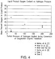
- the present invention pertains to means by which effective hydropyrolysis can be carried out in a single step in a deep fluidized bed of particles of an active catalyst, at H 2 partial pressures from 13.8 to 41.4 bar (200 to 600 psig), in such a manner that the oxygen content of the liquid hydrocarbon product is reduced to below 4% by mass.
- the hydropyrolysis reaction is exothermic and provides the heat of reaction so that there is no need to provide external heating or circulate hot regenerated catalyst or sand through the fluid bed reactor as is typically required for traditional pyrolysis.
- Fluidized beds generally include solid particles, such as particles of sand or catalyst, that are agitated and fluidized by a stream of gas, which travels upward through the bed and exits from the bed at or near the top of the reactor.
- the behavior of fluidized beds is known to at least partially depend on the depth (or height, or length) of the bed.
- the bed depth is generally characterized by the L/D ratio, meaning the ratio of the depth, height, or length of the bed, divided by the bed diameter.
- the behavior of the bed will depend heavily on the particle size distribution of the material from which the bed is formed.
- fluidized beds are designed with an L/D of 1-2, since beds in this range exhibit uniform fluidization, once a flow rate of fluidizing gas, sufficient to bring the bed particles into rapid motion, has been supplied.
- uniform fluidization means that, once fully-fluidized, the particles in the bed are in universal, random motion. Mixing and internal heat transfer within a fully-fluidized bed are both very rapid, and a relatively-shallow bed can often be operated in a nearly-isothermal manner, meaning that the temperature at any point within the bed is almost completely uniform.
- Fluidized beds may be adversely affected by a phenomenon referred to as "slugging.”
- Slugging develops in beds that have L/D ratios greater than 1.5-2.0 and fluidized beds composed of particles larger than a few hundred microns are especially prone to slugging.
- Slugging is a phenomenon in which a gas-filled bubble forms in the bed, and the diameter of the bubble rapidly expands to reach the full diameter of the bed. Then the entire bed above the bubble begins to move upward as a coherent body (a "slug"), with very little relative motion between particles in the "slug.”
- the slug can rise for many bed diameters before the cohesion of the slug begins to break down, and the particles in the slug then drop rapidly back down toward the lower levels of the reactor.
- the bubble forms at an elevation of 1.5-2.0 reactor diameters above the bottom of the bed.
- a region of well-fluidized bed material can be observed in the lowest parts of the bed, with an open space, containing only the fluidizing gas, appearing between the top of the well-fluidized region and the bottom of the coherent slug.
- the bed material from the slug drops down onto the bed material in the lowest parts of the bed, suppressing fluidization until the bubble re-forms and the next slug is lifted.
- Slugging is usually cyclic or periodic, and, once it begins, it can continue with regularity until it is interrupted by a change in operating conditions. Slugging can also be affected by the properties of the bed material. Two beds, of equal depths and bulk densities, may behave very differently if the particle size distribution is different, or the sphericity of the particles in either bed is changed.
- Slugging is undesirable for several reasons. Most importantly, when slugging occurs, longitudinal mixing in the bed is retarded, and particles from the highest points in the bed move very slowly down toward the bottom of the bed (and vice versa). The uniformity of axial temperature is thereby compromised, and considerable gradients in temperature can be observed along the height of the bed. Slugging also creates cyclical stresses on the walls and floor of the bed, particularly if the bed is disposed within a reactor, and the effect of cyclic loading and unloading on the reactor support structure, and the concomitant effect on process chemistry, can destroy any semblance of process uniformity.
- the vibration, or cyclical loading, of the reactor walls and support structure can lead to mechanical failures, and the variation in the process chemistry will also make it impossible to operate with a useful level of process control. Slugging may also significantly increase the attrition of particles that comprise the fluidized bed, because the large-amplitude, cyclical motion of the bed tends to involve the bed particles in more energetic collisions with other particles and with the walls of the vessel within which the bed is contained.
- the problem of slugging can generally be avoided simply by using a shallower bed or, in some cases, using particles of smaller diameters.
- a shallow bed is simply not practical. If the bed has catalytic properties that are essential to the process chemistry, then the weight of catalyst in the fluidized bed may need to be above some threshold, relative to the mass flow rate of vapors passing through the bed, in order for the desired reactions to occur.
- the desired deoxygenation reactions that are required to carry out effective hydropyrolysis cannot be carried out in a shallow fluidized bed of catalyst. If the bed is too shallow, the vapors will exit the bed before the desired effect is achieved.
- the mass flow rate of fluidizing gas required to fluidize a bed also depends on the diameter of the bed. In some situations, particularly in pressurized reactors, the diameter of the bed must be held below a certain value, so that a gas velocity sufficient to fluidize the bed can be achieved with the available mass flow rate of fluidizing gas.
- the process of the present invention preferably includes the use of a deep fluidized bed, composed of relatively large catalyst particles. Because this bed is inherently prone to slugging we have incorporated in this invention a means of curtailing slugging. Slugging is avoided or controlled via the use of an insert or other anti-slugging modification of the hydropyrolysis reactor, which is disposed within the fluidized bed.
- the design and application of the insert within the reactor or other modifications of the hydropyrolysis reactor to inhibit slugging are important aspects of the invention.
- the use of the insert or other anti-slugging modification of the hydropyrolysis reactor makes it possible for the fluidized bed to maintain proper fluidization and be of the required depth to carry out the desired hydropyrolysis reactions.
- the insert further makes it possible for the bed to be composed of relatively-large catalyst particles, which are large enough to be retained in the bed while smaller particles of solid residue (char) are elutriated and carried out of the bed within the gaseous product stream.
- the behavior of a fluidized bed will vary depending on the flow rate of fluidizing gas passing through the bed.
- the process of the present invention specifically involves a bubbling fluidized bed.
- a flow rate of fluidizing gas is supplied that is sufficient to vigorously agitate and mix the bed, and is large enough that open voids, containing almost exclusively fluidizing gas, are formed.
- the flow rate is not large enough to entrain the solid catalyst particles from which the bed is composed in the gaseous exhaust stream and permanently separate them from the bed.
- This invention relates to a process for thermochemically transforming biomass or other oxygenated feedstocks into high quality liquid hydrocarbon fuels.
- a catalytic hydropyrolysis reactor containing a deep bed (length:diameter ratio > 2) of fluidized catalyst particles is utilized.
- the reactor accepts particles of biomass or other oxygenated feedstocks that are significantly smaller than the particles of catalyst in the fluidized bed.
- the reactor features an insert or other structure disposed within the reactor vessel that inhibits slugging of the bed and thereby minimizes attrition of the catalyst.
- the biomass feedstock is converted into a vapor-phase product, containing hydrocarbon molecules and other process vapors, and an entrained solid char product, which is separated from the vapor stream after the vapor stream has been exhausted from the top of the reactor.
- a significant proportion of the hydrocarbons in the product vapor stream can be recovered as a liquid stream of hydrophobic hydrocarbons, containing preferably less than 4% by mass of oxygen, with properties consistent with those of gasoline, kerosene, and diesel fuel.
- Separate streams of gasoline, kerosene, and diesel fuel may also be obtained, either via selective condensation of each type of fuel, or via later distillation of the combined hydrocarbon liquid.
- paper and waste sludges can be substantially converted to obtain a product stream consisting of hydrocarbons that are liquid under ambient conditions, contain preferably less than approximately 4% oxygen by mass, and have properties, such as boiling points, heating values, and aromaticities, that are consistent with those of gasoline, kerosene and diesel fuel.
- the subject invention includes a process for producing liquid products from biomass (or other oxygenated solid, slurry, or liquid feedstock) in which the feedstock is rapidly heated in a reactor vessel containing molecular hydrogen and a deoxygenating catalyst, producing a deoxygenated pyrolysis liquid product having preferably less than approximately 4% oxygen by mass, an aqueous liquid product containing water and water-soluble species, a solid char product, a product stream comprising non-condensable vapors, and process heat.
- the subject invention includes a method of hydropyrolysis comprising the following steps:
- the low oxygen content (generally less than 4% by mass) of the liquid hydrocarbon stream produced by the process of the present invention at low hydrogen partial pressure is desired.
- the high yield of deoxygenated liquid hydrocarbons from biomass feedstock is also desired.
- the gaseous vapors When the highly deoxygenated gaseous hydrocarbons and char encounter a barrier filter, the gaseous vapors preferably contain no high boiling point components that could be adsorbed or reside on char particles and so the highly deoxygenated gaseous hydrocarbons are effectively separated from the char, which can then be easily removed from the filter by minimal levels of backpulsing.
- particles of char In conventional pyrolysis, particles of char adsorb and retain reactive pyrolysis oils. When these particles encounter a barrier filter they aggregate and create a dense, almost impermeable layer of char that resists cleaning by backpulsing.
- the hydropyrolysis reactor vessel of the process of the present invention preferably comprises an elongated deep bed fluidized bed reactor with a bed that preferably includes relatively-large catalyst particles.
- the feedstock is fed into said reactor in the form of particles that are substantially smaller in size than the catalyst particles in the bed, in order to maximize thermal decomposition of the biomass, minimize catalyst particle attrition, and permit effective separation of char from the fluidized bed and from the process vapor stream exiting the fluidized bed.
- one or more inserts or other anti-slugging modifications of the reactor may be disposed within the reactor to inhibit slugging of the fluidized bed during the hydropyrolysis process.
- a particular design approach, pertaining to inserts or other anti-slugging modifications of the hydropyrolysis reactor, is incorporated into the present invention, which makes it possible to prevent slugging of the bed disposed within the fluidized-bed reactor, even under circumstances where slugging would generally be expected to occur.
- hydropyrolysis is used to describe a process by which a biomass feedstock (to include all of the varieties of biomass enumerated in the Summary of the Invention, above) is rapidly heated and thermally decomposed, in the presence of solid catalyst particles and an atmosphere consisting largely of hydrogen gas. Further, the term “hydropyrolysis” will be used to refer to all reactions carried out on the products of thermal decomposition of the feedstock within the hydropyrolysis reactor. In the present invention, hydropyrolysis involves five classes of reactions. They are:
- deoxygenation refers to chemical processes by which chemically-bonded oxygen is removed from molecules (principally hydrocarbon molecules) and transferred to other chemical species such as water (H 2 O), carbon monoxide (CO), or carbon dioxide (CO 2 ).
- hydrodeoxygenation refers to a subset of these processes where water is formed.
- hydrotreating refers to a range of chemical reactions in which hydrocarbon species (which may contain double and triple carbon-carbon bonds, benzene rings, five-carbon rings, chemically-bonded heteroatoms, and a wide variety of other functional groups) are reacted with molecular hydrogen (H 2 ), generally in the presence of a catalyst.
- Hydrotreating generally involves breaking a bond in the hydrocarbon molecule, and adding hydrogen to the structure of the hydrocarbon molecule, so that heteroatoms (such as oxygen and nitrogen) are removed, double and triple carbon-carbon bonds are saturated and substituted with carbon-hydrogen bonds, and ring structures are opened, resulting in linear hydrocarbon molecules.
- Hydrotreating can also involve "hydrocracking" (or “cracking”) which involves the breaking of long hydrocarbon chains into shorter hydrocarbon chains, producing smaller molecules with lower boiling points.
- hydroconversion is defined as a reaction carried out in the presence of hydrogen, and generally a catalyst, which removes heteroatoms such as sulfur, nitrogen and oxygen or carries out cracking while adding hydrogen to the structure of the reactant molecule.
- the catalytic hydropyrolysis process of the present invention provides a means to remove oxygen from biomass and other feedstocks containing significant quantities of carbon and chemically-bonded oxygen to produce light hydrocarbon products with a large portion of the oxygen removed directly from the feedstock-derived liquids. This is referred to as "deoxygenation.”
- deoxygenation In the reactor described in the present invention, deoxygenation of molecules derived from the biomass feedstock inherently releases a large heat of reaction which provides the energy necessary to heat up cold biomass as it enters the bubbling fluid bed.
- one problem with conventional catalytic hydropyrolysis is the separation of the char and ash from the catalyst.
- the reactor described in this invention which involves a bubbling fluidized bed hydropyrolysis system with catalyst particles that are much greater in size than the decomposed (reacted) feedstock residue, provides a novel way of mitigating catalyst attrition while at the same time ensuring that char and ash are separated from the catalyst by being attritted (reduced in size) and elutriated from the bubbling bed reactor.
- Elutriation occurs when a particle has been reduced in size to a point where it is entrained in the stream of gas exiting the top of the fluidized bed, and is removed permanently from the bed.
- the char product of catalytic hydropyrolysis of the feedstock being largely composed of carbon, acts as a lubricant within the bubbling bed and serves to protect the large catalyst particles from self-attrition.
- the action of the bed on the soft char and ash is such that the char and ash are effectively attritted by the catalyst and reduced to a size where the char and ash are readily elutriated from the bubbling bed. The problem of char and ash removal from the fluidized bed of catalyst is thereby addressed.
- the present invention it may be advantageous to process efficiency and quality for more than one type of catalyst to be disposed within the bed.
- two physically and chemically different catalysts could be disposed within the bed. Because the two types of catalyst could be engineered to possess different densities or sizes, the catalysts could intermix within the fluidized bubbling bed, or one catalyst could tend to rise to the top of the bed (e.g. by being lighter or being sized to possess a lower aerodynamic diameter) so that the chemistry of this process can be effected in a stepwise manner.
- a number of catalysts could be disposed so that some could intermix while others would maintain different vertical positions in the bed.
- biomass or other solid feedstock particles are fed into the fluidized-bed catalytic hydropyrolysis reactor preferably near the bottom of the bed, and are rapidly heated and decomposed to produce solid ash, char residue, and vapor-phase products.
- the ash, char and vapors then travel up through the bed, where the process vapors (and solid particles small enough to be aerodynamically entrained) are carried permanently away from the upper surface of the fluidized bed where they exit the reactor.
- a deep fluidized bed particularly one comprised of relatively-large catalyst particles, will develop slugging, and cannot be operated without a slug-breaking insert.
- the insert should consist of obstacles, obstructions, or constrictions, positioned at regular intervals within the bed, and oriented or contoured in such a way that a coherent slug of bed material cannot form along the full length of the bed. The use of the insert makes operation of the reactor with a deep bed possible, and provides three advantages, relative to operation of the reactor with a shallow bed:
- the vapor stream leaving the top of the fluidized bed includes the fluidizing gas, any product vapors that have been generated by thermal decomposition and hydropyrolysis of the feedstock, and any solid particles (ash, char or attritted catalyst fines) that are small enough to be aerodynamically entrained in said vapor stream.
- the process described by this invention specifies that product vapor species leaving the fluidized bed must be sufficiently chemically stable so that they will be substantially unable to react with other product vapor species, or with solids entrained in the vapor stream, or with solid surfaces with which the vapor stream comes into contact, such as a barrier filter.
- the most unstable species produced by the initial thermal decomposition of the feedstock such as aldehydes and acids, should be substantially deoxygenated via reaction with hydrogen in the catalytic fluidized bed.
- the combined stream of vapors and entrained solids can be passed through an inertial separation device such as a cyclone or virtual impactor, an electrostatic precipitator (ESP), and/or filter elements, or some combination of the above, and will not form a dense cake on the cyclone, ESP plate, or filter surfaces, or create fouling as the solid particles are filtered out of the vapor stream.
- an inertial separation device such as a cyclone or virtual impactor, an electrostatic precipitator (ESP), and/or filter elements, or some combination of the above, and will not form a dense cake on the cyclone, ESP plate, or filter surfaces, or create fouling as the solid particles are filtered out of the vapor stream.
- any appropriate inertial separation device, porous filter, electrostatic precipitator, or other means of removing solids from the vapor stream may be employed once the vapor stream (with entrained solids) has exited the reactor containing the fluidized bed. If a cyclone or virtual impactor is used first to remove the larger solids entrained in the vapor stream, and a porous filter is then used to remove the remaining fines entrained in the vapor stream, the majority of the char and ash leaving the reactor can preferentially be collected from the cyclone, while the majority of the attritted catalyst can be recovered from the filter. This is because the catalyst is much harder than the char, and will break down primarily into very fine particles, which will pass through the cyclone to the filter.
- the char is softer and less durable, and will be broken down into a range of particle sizes by the grinding action of the fluidized bed. The larger particles of char will be trapped primarily by the cyclone, and will not reach the filter. Finally, if the catalyst is disposed to remain as a metallic material that can be magnetized, particles comprised of attrited catalysts may be efficiently collected in a filter or inertial separation device that can be periodically energized with a magnetic field to entrap the magnetic particles. Deenergizing the magnetic field would allow these particles to be removed and recovered en masse.
- the vapors can either be cooled to ambient temperature immediately, at which point all species with boiling points below ambient temperature will condense to form liquids, or the stream of process vapors can be directed to a subsequent reactor or reactors for further treatment.
- One approach is to send the filtered process vapors from the hydropyrolysis reactor to a second-stage reactor, where the process vapors can be further hydrogenated using a hydroconversion catalyst.
- This approach can be used to produce a product stream containing substantially fully deoxygenated hydrocarbon species, water vapor, a gaseous mixture comprising CO, CO 2 , and light hydrocarbon gases (C 1 -C 4 ) and further process heat. If this approach is used, the overall process may be referred to as integrated hydropyrolysis and hydroconversion.
- biomass is an ideal feedstock for use in the hydropyrolysis process described above
- the feedstock sent into the fluidized-bed hydropyrolysis reactor need not be biomass, and need not be composed only of solids. Any feedstock which can be subjected to hydropyrolysis, under the conditions described above, and which yields products similar to those described above, could be fed into the reactor.
- feedstock streams containing polymers or plastics, or feedstock streams comprising slurries of solid particles suspended in a carrier liquid, or feedstocks streams comprising a carrier gas, in which solids or liquids are entrained, or feedstock streams comprising, completely or in part, of liquids that can be deoxygenated and reacted with hydrogen to produce deoxygenated hydrocarbons can be subjected to hydropyrolysis via the method described in the present invention. If liquids are present in the feedstock stream these liquids must be able to evaporate and enter the vapor phase very shortly after they are introduced into the fluidized bed.
- the set of reactions occurring in the process of the present invention are primarily vapor-phase reactions, and liquids initially present in the feedstock stream, or formed via chemical decomposition of the feedstock stream, must enter the vapor phase in order to be effectively processed by the fluidized-bed reactor of the present invention.
- a schematic diagram of the process described in the present invention is shown in Figure 1 .
- a fluidizing gas stream 150 consisting primarily of hydrogen, but possibly also containing other gases, is fed into the bottom of a fluidized-bed reactor vessel, 100.
- the fluidizing gas stream passes through a bed of catalyst particles, contained within the fluidized-bed reactor vessel, and fluidizes the bed to a point where its state is consistent with that of a bubbling fluidized bed.
- An insert 130, or other modification to the interior of the vessel, is present, and interacts with the bed 140 in such a way that slugging is prevented.
- the depth of the bed is therefore not limited by the diameter of the vessel, and a deep bed, whose axial dimension may be many times greater than the diameter of the vessel, can therefore be employed.
- the mass flow rate of fluidizing gas, passing through the bed is determined by the size and fluidization characteristics of the catalyst particles.
- the catalyst particles are approximately spherical, and are approximately 3200 microns or more in diameter, but could be smaller or larger.
- the density of each particle can vary from 0.5 to 2 kilograms per liter. Based on laboratory studies, a superficial velocity of fluidizing gas of approximately 1 to 1.5 meters/second is needed to achieve effective fluidization of a bed of this type. The superficial velocity is defined as the average velocity that the fluidizing gas would achieve if it were passing through the empty reactor vessel, in the absence of a fluidized bed.
- the diameter of the vessel is governed primarily by the amount of fluidizing gas available, and the depth of the bed is governed by the amount of catalyst needed to achieve the requisite deoxygenation of the feedstock.
- There is no definite upper limit to the depth of the bed since the use of an anti-slugging insert, or anti-slugging modifications within the reactor, as specified in the present invention, ensures that slugging is avoided, no matter how deep the bed in the reactor becomes.
- the bed should be as deep as necessary to achieve the desired degree of reaction of the process vapors released by the feedstock.
- the mass flow rate of fluidizing gas should not exceed the minimum required to achieve fluidization.
- the distribution of temperature within the fluidized bed as described in the present invention is nearly uniform, due to the rapid exchange of heat between particles in motion throughout in the bed.
- the temperature of the bed must be at least 343 degrees Celsius (650 degrees Fahrenheit) and need not be higher than 593 degrees Celsius (1100 degrees Fahrenheit).
- the exact operating temperature of the bed depends upon the composition of the feedstock that is to undergo hydropyrolysis, the characteristics of the catalyst, and the desired composition of products that is to be obtained.
- the pressure within the fluidized-bed reactor vessel must be such that the partial pressure of hydrogen is about 13.8 to 41.4 bar (200 psig to 600 psig).
- the exact operating pressure of the fluidized-bed reactor depends upon the composition of the feedstock that is to undergo hydropyrolysis, the choice of catalyst, and the desired composition of products that are to be obtained.
- the feedstock that is to undergo hydropyrolysis is fed into the bottom of the fluidized bed, near the point where the fluidizing gas enters the reactor.
- the feedstock is introduced in such a way that it is heated very rapidly from ambient temperature to the temperature of the fluidized bed, by interacting with the fluidized bed.
- the feedstock is introduced into the fluidized bed in such a manner that any solid residues (remaining after the feedstock has been heated to the temperature of the bed) form distinct solid particles, which are significantly smaller in size than the particles of catalyst of which the bed is primarily composed. These particles will then be transported to the top of the bed, and, if they are sufficiently small, they will be entrained in the gas and vapor stream and carried out of the bed.
- the particles will continue to move around in the fluidized bed, and will undergo attrition, until they are small enough to be entrained and carried out of the bed.
- the feedstock is prepared and introduced as distinct, approximately-spherical, particles, up to, but not exceeding, the diameter of the catalyst particles in the bed.
- the rapid heating of the feedstock causes the feedstock to decompose, driving off vapor-phase products of thermal decomposition and leaving behind a solid product (referred to as char) which comprises primarily carbon, but also includes any non-volatile, inorganic material (ash) initially present in the feedstock.
- char solid product
- Individual particles of solid residues remaining after decomposition generally contain both carbonaceous char and ash within a single coherent structure.
- these particles of solid residue consist largely of carbon, and are physically softer than the catalysts that comprise the bed, they are more readily subject to abrasion, attrition, or grinding. They lubricate the catalyst particles as they move within the fluidized bed, and are broken into smaller particles much more rapidly than the particles of catalyst. This lubricating effect provides a significant benefit, since catalyst fines that are ground down to sizes small enough to be entrained in the stream of gas leaving the top of the bed will be carried out of the bed, and no longer be available to promote chemical reactions.
- the lubricating effect of char moving around in the fluidized bed serves to reduce the rate of catalyst attrition, and thereby reduce the need (and cost) for replacement catalyst needed to maintain the desired degree of chemical reactivity within the bed.
- the feedstock undergoes very rapid thermal decomposition into product vapors and a relatively soft solid material composed of char and ash (char being the dominant portion).
- This residue is frequently referred to as char.
- This char is rapidly ground up (attritted) by particles of catalyst in the fluidized-bed reactor, which are significantly larger than the char particles, until the char is sufficiently reduced in size (and aerodynamic diameter) so that its terminal velocity is lower than the upward velocity of the fluidizing gas and product vapors.
- the atlingered char is elutriated and is carried out of the bed while the relatively large and heavy catalyst particles remain behind in the bed.
- the attritted particles of char in this embodiment of the present invention act as a micro-scale lubricant, and reduce attrition of catalyst particles in the fluidized bed.
- catalyst attrition is lower when biomass is hydropyrolyzed in the reactor than it would be if only the fluidized catalyst particles were present.
- the rate at which feedstock is fed into the reactor depends upon the amount of catalyst and partial pressure of hydrogen within the reactor.
- the relationship between the rate at which feedstock is sent into the bed, and the amount of catalyst present in the bed, can be quantified in terms of a volume hourly space velocity (VHSV).
- VHSV can be calculated by dividing the volumetric flow per hour of feedstock sent into the reactor by the bulk volume of the catalyst present in the bed, in the absence of any fluidizing gas flow.
- the hydropyrolysis reactor can be operated over a catalyst VHSV range of 1 hr -1 to 45 hr -1 .
- the exact catalyst VHSV that is appropriate for a given combination of feedstock and catalyst depends on the nature of the feedstock and catalyst, and on the desired composition of the products that are to be obtained.
- the atmosphere in the reactor should consist largely of hydrogen (though other inert gases, like CO 2 , may also be present), and the feedstock flow rate cannot be so great that the vapor-phase products of feedstock decomposition dilute the hydrogen atmosphere to a point where the required partial pressure of hydrogen needed to carry out the desired set of reactions is no longer available.
- the most important reactions that are carried out in the hydropyrolysis reactor as described in the present invention involve deoxygenation of oxygenated hydrocarbon molecules. These oxygenated hydrocarbon molecules contain oxygen that is initially present in the feedstock, and the oxygen is often present in the form of functional groups that make the oxygenated hydrocarbons very chemically reactive.
- the hydropyrolysis reactor of the present invention removes these oxygen atoms from the hydrocarbon molecules with which they are associated. Within the reactor, the oxygen can be converted either into water vapor (H 2 O) or the carbon-containing vapor-phase species carbon monoxide (CO) and carbon dioxide (CO 2 ).
- the CO and H 2 O molecules can react to form CO 2 and H 2 .
- This latter reaction is referred to as a water-gas shift reaction, and, since it liberates an H 2 molecule, it can be useful in reducing the amount of hydrogen that is sent into the reactor in the stream of fluidizing gas.
- the relative amounts of CO, CO 2 and H 2 O that are present in vapors exiting from the top of the fluidized bed in the reactor depends on the feedstock, operating conditions, and catalyst characteristics.
- the set of reactions that occur during deoxygenation of the feedstock release significant net amounts of heat, since the heats of formation of CO, CO 2 , and H 2 O are high enough to overcome the amount of heat required to effect heating and endothermic thermal decomposition of the feedstock, and the chemical decomposition of oxygenated molecules in the process vapors.
- the surplus of heat generated via deoxygenation of the feedstock is at least sufficient to heat the incoming feedstock up to the temperature of the fluidized bed, and supply the heat consumed by any endothermic processes, including evaporation of liquid species, occurring during hydropyrolysis of the feedstock.
- the product gases and vapors exiting the top of the fluidized bed must have certain characteristics, in order for the process described in the present invention to be carried out successfully. First, they must consist largely of hydrogen. Second, small particles of solids (char and ash, as well as attritted catalyst) must be entrained within them. At steady-state, the mass flow rate of entrained solids leaving the top of the fluidized bed must equal the rate at which solid residue is generated by hydropyrolysis of the feedstock in the fluidized bed, plus the rate at which catalyst is being attritted to form fines small enough to be elutriated. Third, the vapors must contain the hydrocarbon species produced when the feedstock is hydropyrolyzed.
- the molecules composing the hydrocarbon vapors must be sufficiently deoxygenated and chemically stabilized so that they do not react rapidly with other hydrocarbon molecules, or with solid surfaces with which they may come into contact.
- the total oxygen content, by mass, of condensable hydrocarbons in the product vapor stream must be 4% or less.
- condensable indicates that the species in question have boiling points of 21 degrees Celsius (70 degrees Fahrenheit) or lower, at atmospheric pressure, or are highly soluble, and not subject to rapid vaporization, when dissolved in a liquid with a boiling point below 21 degrees Celsius (70 Fahrenheit).
- the stream of product gases and vapors exiting the top of the fluidized bed therefore contains hydrogen, water vapor, CO, CO 2 , and entrained solid particles. It also contains hydrocarbon products of hydropyrolysis of the feedstock, including methane, ethane, propane, butane, and a variety of other hydrocarbon molecules with atmospheric-pressure boiling points conforming to those of gasoline, kerosene, and diesel fuel. Some hydrocarbons, with oxygen in their molecular structure, and/or other heteroatoms such as nitrogen, sulfur and phosphorus, may also be present in the vapor stream leaving the fluidized bed. Other vapors, such as H 2 S and ammonia may also be present, depending on the composition of the feedstock. However, the product vapors are sufficiently chemically stable that they can be effectively separated from the entrained solid particles by filtration, inertial, or electrostatic means, without plugging or otherwise impairing the separation devices through which they pass.
- the product vapor stream emanating from the top of the fluidized-bed reactor vessel 100 is kept hot enough to prevent condensation of any liquid product, and then conveyed to one or more particle separation devices 110, 120.
- inertial separation and filtration are employed in series and occur first in a primary separation system 110 (e.g. a cyclone or virtual impactor), which removes larger particles consisting primarily of char and ash.
- the gases and vapors are then conveyed to a hot filtration system 120 (for example, a porous barrier filter that may or may not be enhanced with a magnetic separation step) which removes all remaining entrained solid particles, and may produce a solid stream consisting primarily of catalyst fines from the fluidized bed.
- a hot filtration system 120 for example, a porous barrier filter that may or may not be enhanced with a magnetic separation step
- any other effective means by which the char can be removed from the stream of hot process gases and vapor may be applied.
- the product vapor stream can then be cooled in order to condense the water and condensable liquid hydrocarbon product, or the product vapor stream can be directed to another reactor for further processing.
- the products of hydropyrolysis are cooled to condense liquid products, and transferred to an environment where the pressure is at or near ambient pressure, and the temperature is at or near 21 degrees Celsius (70 degrees Fahrenheit) two liquid phases are recovered.
- One phase floats on top of the other, and this upper phase comprises hydrophobic hydrocarbons, and contains less than approximately 4% by weight of oxygen.
- the lower phase comprises primarily water, as well as any water-soluble species produced by the process.
- the hydrocarbon phase comprises primarily hydrocarbons with properties consistent with those of gasoline, kerosene, and diesel fuel.
- the feedstock subjected to hydropyrolysis comprises primarily of a type of biomass, such as certain species of algae, containing a significant fraction of lipids.
- this type of feedstock will yield significant quantities of deoxygenated diesel oil, which could otherwise be made from lipids extracted from the algae.
- hydropyrolysis of algae containing a significant fraction of lipids will also yield additional gasoline and diesel hydrocarbons which are produced as a result of hydropyrolysis of non-lipid fractions of the algae (cell walls, etc.). This is particularly attractive because lipid extraction from algae, via, for example, hexane-based solvent-stripping, is expensive.
- the process of the present invention is ideal for algae conversion because it can be carried out on algae feedstocks, which are usually only partially dewatered, and still produce high quality diesel and gasoline hydrocarbons as a resulting product.
- the process of this invention provides several distinct advantages over conventional fast-pyrolysis-based processes in that it produces a liquid hydrocarbon product that contains low or negligible amounts of solid char, very little oxygen, is chemically stable, and is hydrophobic.
- Hot filtration of solid char from the product vapor stream is generally not possible with fast-pyrolysis vapors, particularly when biomass is used as the feedstock.
- hot filtration of solid char is readily applied to biomass hydropyrolysis product vapor streams in accordance with the process of the present invention.
- fast pyrolysis of biomass feedstocks does not yield a stream of hydrophobic, deoxygenated liquid product, meaning that recovery of a useable liquid hydrocarbon fuel, from liquids produced via fast pyrolysis of biomass presents a significant technical challenge.
- recovery of a useable stream of liquid hydrocarbon fuel from hydropyrolysis of biomass, via the process of the present invention is straightforward, as described above.
- the water-based (aqueous) liquid product stream produced by this process remains relatively free of dissolved hydrocarbons and will likely contain less than 5% by mass dissolved total organic carbon (TOC). Due to this relatively low TOC concentration, the stream of aqueous liquid product can be handled and disposed of with relative ease.
- the stream of aqueous liquid product will also contain a concentration of dissolved ammonia that will depend on the amount of nitrogen initially present in the feedstock.
- the hydropyrolysis process of the present invention produces primary streams of char, water, steam, hydrogen, hydrocarbon gases such as methane, ethane and propane, and liquid hydrocarbon fuels. These can be integrated with other processes that produce biomass or fuels from related renewable feeds.
- secondary streams of nutrients can be obtained from the hydropyrolysis process of the present invention, which may be useful in promoting biomass growth.
- Ammonia is one such nutrient, which can be recovered from the process of the present invention, and can be used as a fertilizer, in order to promote biomass growth.
- Char obtained from the process can also be used as a soil amendment to improve the cultivation of crops such as corn and sugar cane.
- Biomass feedstocks amenable to production in a process integrated with the process of the present invention include, but are not limited to, algae, jatropha, corn stover, wood, bagasse, switchgrass, miscanthus, and nuts (or nut husks and shells). Processes producing high-value nutraceutical products, obtained from plants or other crops, can also be integrated with the process of the present invention.
- the embodiment of the hydropyrolysis process of the present invention that converts corn stover to liquid transportation fuel can be integrated into facilities which produce ethanol from corn.
- the water and steam produced by hydropyrolysis of corn stover could find use in the production of corn ethanol, which typically requires both energy and water as inputs. Wastes from the corn ethanol production can likewise be utilized as feeds for the hydropyrolysis process.
- the biomass hydropyrolysis process also can be integrated into a petroleum refinery.
- the char from the hydropyrolysis process can be burned to produce energy in refinery furnaces thereby reducing refinery greenhouse gas emissions, since CO 2 emissions from renewable sources do not count as greenhouse gas emissions.
- the hydrocarbon liquids from the hydropyrolysis process can go directly to the refinery hydrotreating units for further upgrading and are fully compatible.
- the C1-C3 hydrocarbon gases from the hydropyrolysis unit can go to the hydrogen plant to make the hydrogen required for the hydropyrolysis.
- the catalyst preferably includes several characteristics:
- the hydropyrolysis catalyst of the present invention is disposed within a fluidized-bed reactor, and the bed of catalyst has an L/D ratio significantly greater than 2. Slugging of the bed, during operation, is avoided via the use of an anti-slugging insert or other anti-slugging modification of the reactor (described in greater detail below).
- the size of the catalyst particle is determined by the smallest size to which solid particles in the feedstock stream can be reduced, without compromising the practicality or commercial viability of the process. Generally, if particles of a solid feedstock, such as biomass, are reduced below approximately 2800 microns in a commercial operation, the cost of grinding and preparation of the feedstock can significantly rise.
- a particle size of 3200 microns or more is generally specified for the catalysts in accordance with the process of the present invention.
- the catalyst particle size may then be reduced, providing that the catalyst particles remain large enough to be effectively retained in the fluidized bed while the solid residues of hydropyrolysis are elutriated.
- the process requires an active catalyst that effectively deoxygenates and chemically stabilizes the hydropyrolysis vapors, but that is not so catalytically active that it rapidly cokes.
- the catalyst in the fluidized bed of the present invention can be any highly active deoxygenation catalyst which reduces the collective oxygen content of produced hydrocarbon vapors with more than four carbons in their molecular structure (C 4 + hydrocarbons) to less than 4% oxygen.
- the catalyst in the fluidized bed must meet the requirements outlined above, and carry out the requisite reactions at a VHSV of greater than 1 hr -1 .
- the catalyst comprises spherical particles of porous alumina or some other appropriate support, which have been impregnated with catalytic material consisting of Nickel and Molybdenum (NiMo) or Cobalt and Molybdenum (CoMo), and have then been sulfided.
- Catalysts comprising sulfided NiMo or CoMo on a porous alumina support material have been shown to be good catalysts for hydropyrolysis and exhibit good deoxygenation activity in experimental testing.
- spherical catalyst particles are required in fluidized beds to minimize attrition. If catalysts are not spherical they will quickly attrit, and excess catalyst losses will occur that can threaten the economic viability of the process.
- the catalyst comprises spherical particles of porous alumina or some other appropriate support impregnated with nickel, or cobalt, or iron, or other metals which can be used for hydrotreating.
- Any metal or combination of metals, impregnated into an appropriate support, which is appropriate for use in hydrotreating, can also be used as a hydropyrolysis catalyst in the process of the present invention, as long as the resulting material displays sufficient catalytic activity to reduce the collective oxygen content of the C 4 + hydrocarbon vapors present in the hydropyrolysis product stream to less than 4% by mass, while releasing enough exothermic heat of reaction to maintain a stable fluidized bed temperature in the hydropyrolysis reactor.
- the feedstock comprises solid biomass particles comprising a bulk density of approximately 0.2 to 0.4 kilograms per liter, and the catalyst particles comprise a bulk density of approximately 0.7 to 1.2 kilograms per liter.
- the difference in the bulk density of the feedstock and catalyst in this embodiment ensures that the solid residue (char) of biomass hydropyrolysis is rapidly conveyed through the fluidized bed and elutriated.
- the fluidized bed of catalyst particles of the present invention is deep enough that it is prone to slugging.
- an anti-slugging insert or other anti-slugging modification of the reactor vessel is employed.
- one or more inserts 130 such as that shown schematically in Fig. 1 , are included and/or installed in the fluidized-bed reactor 100, preventing the formation of slugs, and enabling rapid, uniform axial and radial mixing in deep beds.
- this approach is applied in a hydropyrolysis reactor, where unusually deep fluidized beds 140, composed of large particles, are employed.
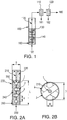
- Figure 2 shows a reactor having a vessel wall 230 defining a fluidized bed 240 into which feedstock particles 260 are fed along with a fluidizing gas stream 250.
- Process vapors 220 are schematically shown leaving the fluidized bed 240.
- slugging is minimized or prevented via the installation of lateral obstructions 200 installed on a central support rod, as shown in Figure 2A .
- the obstructions 200 extend at least part of the way from the centerline of the reactor to the reactor wall 230, on at least one side of the center line. In a preferred embodiment, the obstructions extend all the way across the reactor, and, at their longest point, have a length that is equal to the reactor diameter, D.
- the width of the obstruction, W is such that the obstruction covers approximately 40% of the cross-sectional area of the reactor.
- the obstructions 200 are installed at regular axial intervals, H, equivalent in length to approximately one to two diameters of the bed.
- the orientations (shown in Figure 2B as 1, 2, 3) of the obstructions 200 are adjusted so that the axis of each obstruction is separated by 60 degrees of rotation from the axis of the obstructions above and below it, as shown in the top-down view in Figure 2B . This arrangement ensures that a coherent slug of bed particles, occupying the full diameter of the reactor, cannot form, and cannot propagate along the axis of the reactor.
- the obstructions should be installed in such a way that they extend along the full height of the fluidized bed, L, once the bed is fully fluidized.
- the top of the fluidized bed should extend less than one reactor diameter, D, past the top of the uppermost obstruction.
- a wide range of obstruction geometries can be applied to disrupt the formation of slugs in the bed, including rectangular tabs, obstructions with triangular cross sections, obstructions with diamond-shaped cross-sections, obstructions with oval cross-sections, gratings, etc.
- Open areas in the obstructions, or open areas of the reactor cross section are preferably not aligned with each other, and should overlap as little as possible, when seen from above.
- Dead spots in the fluidized bed 240 may form on the upper surface of obstructions 200, if the obstructions are not designed correctly. In a dead spot, solid particles come to rest on the upper surface of the obstruction, and do not move around in the fluidized bed. In order to prevent this effect, the upper surface of the obstructions should be sloped, peaked, or rounded, so that bed material cannot rest on the top surface of the obstruction.
- Another approach to suppress the formation of dead spots is to employ a porous insert or insert that employs a porous upper portion so that hydrogen, for example, can be made to flow through the central support 210 and be conveyed to the porous or partially porous slug-breaking cylindrical obstructions deployed along the length of the central support 210.
- the type of obstruction 200 shown in Figure 2 can be used to prevent slugging in beds with very large length to depth (L/D) ratios, because a slug tends to require an unobstructed path of axial travel equal to approximately 1 to 2 bed diameters to form, and the installation of these obstructions interrupts the slug just as it would begin to become coherent. Since the obstructions are placed at intervals of approximately one to two diameters, D, there is no section of the fluidized bed 240 within which a coherent slug can form.
- the action of the bed 240 will tend to abrade the material of the obstructions 200, and may limit the useful lifetime of the obstructions 200.
- the insert may be constructed in such a way that it is easily removed and replaced.
- the obstructions and central support of the insert can be made to be highly abrasion-resistant, by, for example, making them from a ceramic or glass-ceramic material or from a ceramic-coated material.
- a combination of materials could also be used, where, for example, those components likely to see the most wear are made of an extremely hard material, and other components, such as the central support rod 210, are made of metal.
- the surfaces of the insert and the vessel walls 230 can be formulated so that they are also catalytically active, and contribute to the catalytic activity needed to complete the process chemistry in the reactor.
- the lateral obstructions 200 are equipped with means by which they can be heated or cooled, and/or are equipped with instrumentation allowing the local temperature of the fluidized bed 240 to be measured and/or regulated.
- the lateral obstructions 200 are not attached to a central support, but are attached to, or installed directly upon, the reactor vessel wall 230. If this embodiment is applied, the obstructions cannot be easily removed from the reactor, and replaced, as part of a single coherent insert. However, this embodiment allows access to the interior of each obstruction, through the location at the vessel wall where the obstruction is attached. Means of heat transfer, instrumentation, and/or steam generation can then be applied within each obstruction 200, through the locations where the obstructions 200 are attached to the vessel wall 230.
- Constrictions 300 of the bed diameter can have the same slug-breaking effect created by lateral obstacles or obstructions 200.
- one or more inserts 130 such as that shown schematically in Figure 1 , are included and/or installed in the fluidized-bed reactor 100, preventing the formation of slugs, and enabling rapid, uniform axial and radial mixing in deep beds. As described above, this approach is applied in a hydropyrolysis reactor, where unusually deep fluidized beds 140, composed of large particles, are employed.
- FIG. 3 shows a reactor having a vessel wall 330 defining a fluidized bed 340 into which feedstock particles 360 are fed along with a fluidizing gas stream 350.
- Process vapors 320 are schematically shown leaving the fluidized bed 340.
- slugging is minimized or prevented via the installation of constrictions of the reactor cross-section, 300 installed on a circumferential support, as shown in Figure 3 .
- the cross-sectional area, A, of the constriction 300 is such that the constriction covers approximately 40% of the cross-sectional area of the reactor.
- the constrictions 300 are installed at regular axial intervals, H, equivalent in length to approximately one to two diameters of the bed.
- the orientation of the constrictions 300 is adjusted so that the centerline of the open area of each constriction is separated by 120 degrees of rotation from the centerline of the open area of the constrictions above and below it, as shown in the top-down view in Figure 3B .
- This arrangement ensures that a coherent slug of bed particles, occupying the full diameter of the reactor, cannot form, and cannot propagate along the axis of the reactor.
- the constrictions should be installed in such a way that they extend along the full height of the fluidized bed, L, once the bed is fully fluidized.
- the top of the fluidized bed should extend less than one reactor diameter, D, past the top of the uppermost constriction.
- a wide range of constriction geometries can be applied to disrupt the formation of slugs in the bed, including constrictions with multiple openings, rounded contours, irregular contours, etc.
- Open areas in the constrictions, or open areas of the reactor cross section not blocked by the constrictions, are preferably not aligned with each other, and should overlap as little as possible, when seen from above.
- dead spots in the fluidized bed 340 may form on the upper surface of constrictions 300, if the constrictions are not designed correctly.
- the upper surface of the constriction should be sloped, peaked, or rounded, so that bed material cannot rest on the top surface of the obstruction.
- Another approach to suppress the formation of dead spots is to employ a porous constriction or constriction that employs a porous upper portion so that hydrogen, for example, can be made to flow through tubes deployed along the circumferential support 310 and be conveyed to the porous or partially porous slug-breaking cylindrical obstructions deployed along the length of the central support 310.
- constriction 300 shown in Figure 3 can be used to prevent slugging in beds with very large length to depth (L/D) ratios, because a slug tends to require an unobstructed path of axial travel equal to approximately 1 to 2 bed diameters to form, and the installation of these constrictions interrupts the slug just as it would begin to become coherent. Since the constrictions are placed at intervals of approximately one to two diameters, D, there is no section of the fluidized bed 340 within which a coherent slug can form.
- the action of the bed 340 will tend to abrade the material of the constrictions 300, and may limit the useful lifetime of the constrictions 300.
- the insert may be constructed in such a way that it is easily removed and replaced.
- the constrictions and circumferential support of the insert can be made to be highly abrasion-resistant, by, for example, making them from a ceramic or glass-ceramic material, or from a ceramic-coated material.
- a combination of materials could also be used, where, for example, those components likely to see the most wear are made of an extremely hard material, and other components are made of metal.
- the surfaces of the insert and the vessel walls 330 can be formulated so that they are also catalytically active, and contribute to the catalytic activity needed to complete the process chemistry in the reactor.
- the constrictions are equipped with means by which they can be heated or cooled, and/or are equipped with instrumentation allowing the local temperature of the fluidized bed 340 to be measured and/or regulated.
- the constrictions 300 are not attached to a removable support, but are attached to, or installed directly upon, the reactor vessel wall 330. If this embodiment is applied, the constrictions cannot be easily removed from the reactor, and replaced, as part of a single coherent insert. However, this embodiment allows access to the interior of each constriction, through the location at the vessel wall where the constriction is attached. Means of heat transfer, instrumentation, and/or steam generation can then be applied within each constriction 300, through the locations where the constrictions 300 are attached to the vessel wall 330.
- Each type of slug-breaking obstacle can be installed either on a central support, extending along the axis of the reactor, or on a circumferential support, extending around the exterior of the reactor. There is no requirement that a particular type of slug-breaking feature be installed on a particular type of support in order for it to be effective.
- the vertical cross-section of a slug-breaking feature may be contoured to remove or accentuate sharp angles. More rounded contours will be more wear-resistant, while more sharp-edged contours may break slugs more effectively.
- the refractory can be molded or cast in such a way that the slug-breaking features are integral to the reactor lining.
- Combinations of obstructions and constrictions of different shapes, or alternating obstructions (attached to a central support) and constrictions (projecting into the bed from the circumference of the reactor) may provide optimal bed motion.
- Obstructions and constrictions need not be installed horizontally across the reactor and can be installed at some angle other than 90 degrees relative to the central axis of the bed.
- Obstructions can be circular or rounded in cross section, when seen from the top of the reactor.
- obstructions can project from a central support on only one side of the centerline of the reactor, extending outward toward the wall of the reactor. As long as obstructions of this type are properly arranged, the formation of slugs may be effectively disrupted.
- the obstructions or constrictions at each location in the reactor should create a pressure drop equal to about 10-20% of the total pressure drop that the entire fluidized bed would create if there were no obstructions or constrictions present.
- obstructions or constrictions deployed within the fluidized bed can incorporate heat exchangers so that they can perform the dual function of mitigating slug formation and managing bed temperature increases associated with the exothermic nature of the present invention.
- These heat exchangers can be used to create process steam (e.g. converting liquid water to steam) or to use liquids to refine temperature distributions within the bed that may be caused by deploying catalysts of differing activity that will stratify and segregate into distinct layers within the bed by choice of density, aerodynamic diameter, or both.
- Fluidized beds expand as fluidizing gas is passed through them, so they are most readily compared on an unexpanded basis.
- the unexpanded depth of the bed is the depth of the bed when no fluidizing gas is passing through it.
- Beds with an unexpanded L/D near 6 were studied in two clear plastic tubes.
- One tube had an inner diameter of 3.33 centimeters, and the other had an inner diameter of 7.62 centimeters.
- the smaller tube had a grid at its base for distribution of fluidizing gas.
- the tube with the larger diameter had an inverted conical base, with a 90 degree included angle in the cone, and a central gas jet at the apex of the cone.
- Beds of the alumina spheres described above, were found to require a characteristic minimum fluidization velocity (Uf) of approximately 0.61 meters/second to 0.76 meters per second.
- the minimum fluidization velocity, Uf is the velocity at which the pressure drop across the bed ceases to rise with increasing superficial gas velocity through the bed, but at which no motion is observed in the bed.
- the insert consisted of a metal rod, located at the centerline of the tube, with various obstructions and obstacles installed on it in order to break up the coherent slug of alumina spheres.
- Each tab obstructed approximately 20% of the cross-sectional area of the tube, and reached from the central rod to the reactor wall, meaning that the fluidizing gas had to accelerate as it passed each tab, and the bed particles in the slug had to rearrange themselves in order to pass around this obstacle.
- the tabs were installed at axial intervals of 7.62 centimeters, with the lowest tab located 7.62 centimeters above the base of the tube.
- tabs Two arrangements of tabs were examined: In one, the tabs were placed on alternating sides of the reactor with the orientation of each tab separated from that of the next in line by 180 degrees; in the other, they were arranged so that each tab was oriented 120 degrees from the tab above and below.
- a protocol to examine the rate of mixing was developed, which involved depositing a layer of red spheres on top of the white spheres in the bed, and then starting a stopwatch at the same time that the fluidizing gas flow was sent through the bed. When red balls first became visible at the very bottom of the bed, the stopwatch was stopped, and this was then referred to as the characteristic mixing time observed for the bed, under a given set of experimental conditions.
- the characteristic mixing time of the bed, in the absence of any slug-breaking insert, was found to be: 15 seconds. Slugging was observed to occur.
- the characteristic mixing time obtained with tabs arranged at 180 degrees was found to be: 5.3 seconds. Slugging was not observed to occur.
- the characteristic mixing time obtained with tabs arranged at 120 degrees was found to be: 5.0 seconds. Slugging was not observed to occur.
- Catalyst particles consisting of a porous alumina support, impregnated with a sulfided cobalt-molybdenum material were used in Case 2 (Catalyst B).
- the fluidized bed in Case 1 was kept at a slightly different temperature than in Case 2.
- FIG. 4 presents a graph that relates oxygen content in liquid hydrocarbon products to the partial pressure of hydrogen used during processing.
Landscapes
- Chemical & Material Sciences (AREA)
- Oil, Petroleum & Natural Gas (AREA)
- Engineering & Computer Science (AREA)
- Organic Chemistry (AREA)
- Chemical Kinetics & Catalysis (AREA)
- General Chemical & Material Sciences (AREA)
- Life Sciences & Earth Sciences (AREA)
- Wood Science & Technology (AREA)
- Combustion & Propulsion (AREA)
- Materials Engineering (AREA)
- Production Of Liquid Hydrocarbon Mixture For Refining Petroleum (AREA)
- Devices And Processes Conducted In The Presence Of Fluids And Solid Particles (AREA)
Claims (25)
- Procédé d'hydropyrolyse comprenant :a. l'introduction d'une charge d'alimentation organique oxygénée comprenant des particules solides de biomasse dans le réacteur à lit fluidisé, dans lequel ladite charge d'alimentation est rapidement chauffée de la température ambiante à la température du lit fluidisé, subit une rapide décomposition thermique en des vapeurs de produit et en un matériau solide mou composé d'un produit de carbonisation, et est ainsi dévolatilisée ;
et moyennant quoi ce produit de carbonisation est rapidement attrité par les particules de catalyseur dans le réacteur à lit fluidisé, qui sont plus grandes de façon significative que les particules de produit de carbonisation, jusqu'à ce que le produit de carbonisation soit suffisamment réduit en termes de taille de sorte que sa vélocité terminale soit inférieure à la vélocité vers le haut du gaz de fluidisation et des vapeurs de produitb. l'introduction d'un courant de gaz de fluidisation comprenant principalement de l'hydrogène moléculaire dans le réacteur à lit fluidisé, créant des conditions dans lesquelles un mélange rapide et un transfert de chaleur se produisent à travers le lit fluidisé, alors que les particules attritées du produit de carbonisation agissent en tant que lubrifiant à échelle microscopique, et réduisent l'attrition des particules de catalyseur dans le lit fluidisé, et fluidisant le lit à un point où son état est cohérent avec celui d'un lit fluidisé à bulles ;c. le maintien d'un lit profond de particules solides de catalyseur, la profondeur de celui-ci est supérieure à deux diamètres de réacteur, dans un état de mouvement vigoureux, afin de promouvoir des réactions produisant une désoxygénation et une stabilisation chimique de vapeurs produites lorsque la charge d'alimentation est dévolatilisée,
dans lequel les particules solides de biomasse comprennent la charge d'alimentation, et dans lequel la taille de particule des particules de catalyseur dans le lit fluidisé est plus grande de façon significative que la taille des particules solides de l'alimentation en biomasse dans la dimension la plus importante ;d. l'élimination des résidus solides, restant après la volatilisation et l'hydropyrolyse de la charge d'alimentation, à partir du réacteur à lit fluidisé par l'intermédiaire d'un entraînement dans le courant de gaz de fluidisation et de vapeurs de produit sortant du réacteur à lit fluidisé ;e. l'élimination du produit de carbonisation attrité, qui est élutriée et réalisée à partir du réacteur à lit fluidisé par l'intermédiaire d'un entraînement dans le courant et de vapeurs de produit sortant du réacteur à lit fluidisé alors que les particules de catalyseur relativement grandes et lourdes restent à l'arrière dans le lit ;f. la séparation des résidus solides, entraînés dans le courant de gaz de fluidisation et des vapeurs de produit sortant du réacteur à lit fluidisé, à partir du courant de gaz de fluidisation et des vapeurs de produit sortant du réacteur à lit fluidisé ;g. la récupération d'un courant de produit de vapeurs d'hydrocarbures comprenant des espèces d'hydrocarbures avec des points d'ébullition à pression atmosphérique, cohérents avec ceux d'au moins parmi l'essence, le kérosène et le carburant diesel, à partir du processus d'hydropyrolyse en tant que liquide condensé ;h. la libération de suffisamment de chaleur exothermique à partir des réactions de désoxygénation se produisant pendant l'hydropyrolyse de la charge d'alimentation afin de fournir de la chaleur de traitement nécessaire par des processus endothermiques se produisant pendant l'hydropyrolyse de la charge d'alimentation, y compris des réactions chimiques, le chauffage de la charge d'alimentation et l'évaporation de liquides ;caractérisé en ce que le pistonnage dans le lit fluidisé est contrôlé par l'intermédiaire de l'utilisation de l'équipement incorporant des obstructions, des obstacles ou des constrictions latéraux, un axe ou une ligne médiane de l'équipement coupant une ligne médiane du réacteur à fluidisé,
dans lequel les obstructions, les obstacles ou les constrictions sont installés à des emplacements verticaux le long du réacteur à lit fluidisé qui sont séparés l'un de l'autre par un ou deux diamètres de réacteur. - Procédé selon la revendication 1, dans lequel le courant récupéré de liquide condensé contient moins de 4 % en masse d'oxygène.
- Procédé selon la revendication 1, dans lequel les particules solides de catalyseur sont résistantes à l'attrition.
- Procédé selon la revendication 1, dans lequel la relation entre un taux d'alimentation volumétrique de particules de charge d'alimentation solide et un volume du réacteur à lit fluidisé est telle que la vélocité spatiale horaire volumique (VHSV) du réacteur est comprise entre 1 et 40.
- Procédé selon la revendication 1, dans lequel la charge d'alimentation ne contient pas d'eau.
- Procédé selon la revendication 1, dans lequel la charge d'alimentation est seulement partiellement déshydratée et contient un peu d'eau.
- Procédé selon la revendication 1, dans lequel la charge alimentation comprend des particules solides d'un polymère oxygéné tel que le téréphtalate de polyéthylène.
- Procédé selon la revendication 1, dans lequel la charge d'alimentation comprend une charge d'alimentation de biomasse complètement ou partiellement déshydratée qui a une teneur élevée en lipides, telle qu'une algue riche en lipides.
- Procédé selon la revendication 1, dans lequel la charge d'alimentation comprend un matériau organique d'origine aquatique tel que le poisson, les parties de poisson et les résidus résultant de la transformation du poisson.
- Procédé selon la revendication 1, dans lequel la charge d'alimentation comprend des matériaux fabriqués ou autrement obtenus à partir de biomasse, tels que des produits et résidus de papier rejetés en tant que courants de déchets par des usines à papier.
- Procédé selon la revendication 1, dans lequel la charge alimentation comprend un matériau organique d'origine animale, tel que les abats, les matières grasses, les graisses et les tissus.
- Procédé selon la revendication 1, dans lequel la charge d'alimentation comprend un matériau organique de déchets d'origine animale tel le fumier ou la vase des eaux d'égout.
- Procédé selon la revendication 1, dans lequel la charge alimentation est introduite dans le réacteur en tant que courant comprenant des particules solides entraînées dans un courant de gaz de transport se déplaçant rapidement, et dans lequel le transport de la charge d'alimentation dans le lit fluidisé est principalement accompli par l'intermédiaire de l'action du gaz de transport sur les particules solides de la charge d'alimentation.
- Procédé selon la revendication 1, dans lequel la charge alimentation comprend une boue de particules solides, suspendues dans un liquide porteur qui s'évapore lorsqu'il est introduit dans le réacteur
- Procédé selon la revendication 1, dans lequel la charge alimentation comprend un liquide organique oxygéné, qui subit une hydropyrolyse dans le procédé d'hydropyrolyse.
- Procédé selon la revendication 1, dans lequel les obstructions, les obstacles ou les constrictions sont équipés d'au moins un moyen de détection de température et d'un moyen par lequel de la chaleur peut être éliminée à partir du lit fluidisé ou ajoutée à celui-ci, d'une manière telle que la température du lit fluidisé autour des obstructions, des obstacles ou des constrictions peut être suivie et/ou régulée.
- Procédé selon la revendication 1, dans lequel les orientations des obstructions, obstacles ou constrictions, sont variées, lorsque qu'elles sont vues à partir d'une partie supérieure du réacteur, de sorte qu'un passage unique, ouvert, courant sur la longueur du réacteur pendant une distance de plus de deux diamètres de réacteur, n'est pas présent.
- Procédé selon la revendication 1, dans lequel l'équipement est au moins partiellement construit d'un matériau à base de céramique dure ou à base de vitrocéramique.
- Procédé selon la revendication 1, dans lequel l'équipement est au moins partiellement recouvert d'un parmi un revêtement résistant à l'abrasion élevée et d'un matériau à base de céramique dure ou à base de vitrocéramique.
- Procédé selon la revendication 1, dans lequel les surfaces de l'équipement sont actives de manière catalytique, et facilitent les réactions d'hydropyrolyse.
- Procédé selon la revendication 1, dans lequel l'équipement comprend un insert avec un support situé de manière centrale, courant le long de l'axe central du réacteur à lit fluidisé, auquel les obstructions, les obstacles ou les constrictions sont attachés.
- Procédé selon la revendication 1, dans lequel l'équipement comprend un insert avec un support de manière circonférentielle, disposé autour de la circonférence du réacteur, auquel les obstructions, les obstacles ou les constrictions sont attachés.
- Procédé selon la revendication 1, dans lequel l'équipement comprend un insert avec un support de manière circonférentielle, disposé autour de la circonférence du réacteur, avec des voies de gaz disponibles pour se connecter à des emplacements auxquels les obstructions poreuses, les obstacles poreux ou les constrictions poreuses sont attachées.
- Procédé selon la revendication 1, dans lequel l'équipement comprend des obstructions, des obstacles ou des constrictions qui sont attachés directement à, supportés par, et en communication avec la paroi du réacteur à lit fluidisé.
- Procédé selon la revendication 1, dans lequel les modifications qui commandent le pistonnage dans le réacteur à lit fluidisé incorporent des voies d'écoulement d'échange de chaleur interne reliées à une tuyauterie externe qui est isolée de l'environnement interne du réacteur à travers lesquels des liquides et des gaz peuvent être passés afin d'extraire de la chaleur du réacteur.
Applications Claiming Priority (3)
| Application Number | Priority Date | Filing Date | Title |
|---|---|---|---|
| US13/089,010 US8841495B2 (en) | 2011-04-18 | 2011-04-18 | Bubbling bed catalytic hydropyrolysis process utilizing larger catalyst particles and smaller biomass particles featuring an anti-slugging reactor |
| PCT/US2012/030386 WO2012145123A1 (fr) | 2011-04-18 | 2012-03-23 | Procédé d'hydropyrolyse catalytique sur lit à bulles utilisant des particules de catalyseur plus grandes et des particules de biomasse plus petite ayant un réacteur anti-coup de liquide |
| EP12711545.9A EP2699642B1 (fr) | 2011-04-18 | 2012-03-23 | Procédé d'hydropyrolyse catalytique sur lit à bulles utilisant des particules de catalyseur plus grandes et des particules de biomasse plus petite ayant un réacteur anti-coup de liquide |
Related Parent Applications (2)
| Application Number | Title | Priority Date | Filing Date |
|---|---|---|---|
| EP12711545.9A Division-Into EP2699642B1 (fr) | 2011-04-18 | 2012-03-23 | Procédé d'hydropyrolyse catalytique sur lit à bulles utilisant des particules de catalyseur plus grandes et des particules de biomasse plus petite ayant un réacteur anti-coup de liquide |
| EP12711545.9A Division EP2699642B1 (fr) | 2011-04-18 | 2012-03-23 | Procédé d'hydropyrolyse catalytique sur lit à bulles utilisant des particules de catalyseur plus grandes et des particules de biomasse plus petite ayant un réacteur anti-coup de liquide |
Publications (2)
| Publication Number | Publication Date |
|---|---|
| EP3190165A1 EP3190165A1 (fr) | 2017-07-12 |
| EP3190165B1 true EP3190165B1 (fr) | 2020-07-15 |
Family
ID=45922854
Family Applications (2)
| Application Number | Title | Priority Date | Filing Date |
|---|---|---|---|
| EP17156919.7A Active EP3190165B1 (fr) | 2011-04-18 | 2012-03-23 | Processus d'hydropyrolyse catalytique à lit bouillonnant utilisant des particules de catalyseur plus grandes et de plus petites particules de biomasse comportant un réacteur anti-pistonnage |
| EP12711545.9A Active EP2699642B1 (fr) | 2011-04-18 | 2012-03-23 | Procédé d'hydropyrolyse catalytique sur lit à bulles utilisant des particules de catalyseur plus grandes et des particules de biomasse plus petite ayant un réacteur anti-coup de liquide |
Family Applications After (1)
| Application Number | Title | Priority Date | Filing Date |
|---|---|---|---|
| EP12711545.9A Active EP2699642B1 (fr) | 2011-04-18 | 2012-03-23 | Procédé d'hydropyrolyse catalytique sur lit à bulles utilisant des particules de catalyseur plus grandes et des particules de biomasse plus petite ayant un réacteur anti-coup de liquide |
Country Status (17)
| Country | Link |
|---|---|
| US (2) | US8841495B2 (fr) |
| EP (2) | EP3190165B1 (fr) |
| JP (2) | JP6133272B2 (fr) |
| KR (2) | KR102039965B1 (fr) |
| CN (2) | CN105001897B (fr) |
| AU (1) | AU2012246685B2 (fr) |
| BR (1) | BR112013026816B1 (fr) |
| CA (1) | CA2833347C (fr) |
| CL (1) | CL2013003009A1 (fr) |
| DK (2) | DK2699642T3 (fr) |
| EC (1) | ECSP13013030A (fr) |
| MX (2) | MX350821B (fr) |
| MY (2) | MY164844A (fr) |
| RU (2) | RU2611631C2 (fr) |
| UA (1) | UA116332C2 (fr) |
| WO (1) | WO2012145123A1 (fr) |
| ZA (2) | ZA201307636B (fr) |
Families Citing this family (50)
| Publication number | Priority date | Publication date | Assignee | Title |
|---|---|---|---|---|
| US11084311B2 (en) | 2008-02-29 | 2021-08-10 | Illinois Tool Works Inc. | Receiver material having a polymer with nano-composite filler material |
| US8841495B2 (en) | 2011-04-18 | 2014-09-23 | Gas Technology Institute | Bubbling bed catalytic hydropyrolysis process utilizing larger catalyst particles and smaller biomass particles featuring an anti-slugging reactor |
| WO2013049368A1 (fr) | 2011-09-27 | 2013-04-04 | Thermochem Recovery International, Inc. | Système et procédé pour l'épuration de gaz de synthèse |
| CN106085469B (zh) * | 2011-11-04 | 2020-01-17 | 国际热化学恢复股份有限公司 | 用于原料向油和气的弹性转化的系统和方法 |
| BR112014011536B1 (pt) | 2011-11-14 | 2020-02-18 | Shell Internationale Research Maatschappij B.V. | Processo para converter biomassa em produtos |
| JP2015523061A (ja) | 2012-05-17 | 2015-08-13 | シエル・インターナシヨネイル・リサーチ・マーチヤツピイ・ベー・ウイShell Internationale Research Maatschappij Beslotenvennootshap | バイオマス材料を処理する方法およびシステム |
| ES2613859T3 (es) * | 2012-10-08 | 2017-05-26 | Shell Internationale Research Maatschappij B.V. | Proceso para la licuación de un material celulósico |
| EP2969209A2 (fr) * | 2013-03-12 | 2016-01-20 | Anellotech, Inc. | Régénération d'un catalyseur pour pyrolyse catalytique rapide |
| BR112016017226B1 (pt) | 2014-01-28 | 2022-01-25 | Shell Internationale Research Maatschappij B.V. | Processo para produzir produtos de hidrocarboneto líquido |
| AU2015282725B2 (en) | 2014-07-01 | 2017-11-30 | Shell Internationale Research Maatschappij B.V. | Conversion of solid biomass into a liquid hydrocarbon material |
| WO2016001163A1 (fr) | 2014-07-01 | 2016-01-07 | Shell Internationale Research Maatschappij B.V. | Conversion d'une biomasse solide en susbtance hydrocarbonée liquide |
| CA2953857C (fr) | 2014-07-01 | 2022-10-25 | Shell Internationale Research Maatschappij B.V. | Conversion de biomasse solide en un materiau hydrocarbure liquide |
| CN106795443B (zh) | 2014-07-17 | 2022-05-13 | 沙特基础全球技术有限公司 | 在加氢热解过程中使用氢供体料流改质贫氢料流 |
| CA2973818A1 (fr) * | 2014-12-18 | 2016-06-23 | Inaeris Technologies, Llc | Procede de thermolyse de biomasse en presence de sulfure d'hydrogene |
| US10308877B2 (en) * | 2014-12-29 | 2019-06-04 | Shell Oil Company | Process for production of aromatics via pyrolysis of lignin-comprising material |
| DE102015108552A1 (de) * | 2015-02-27 | 2016-09-01 | Fraunhofer-Gesellschaft zur Förderung der angewandten Forschung e.V. | Pyrolyseöl und Verfahren zu dessen Herstellung |
| US10392566B2 (en) | 2015-04-27 | 2019-08-27 | Gas Technology Institute | Co-processing for control of hydropyrolysis processes and products thereof |
| BR112018005995A2 (pt) * | 2015-09-25 | 2018-10-23 | Shell Int Research | conversão de biomassa em metano |
| EP3433340B1 (fr) | 2016-03-25 | 2022-06-29 | ThermoChem Recovery International, Inc. | Système de génération de produit gazeux intégré en énergie à trois étapes |
| US10364398B2 (en) | 2016-08-30 | 2019-07-30 | Thermochem Recovery International, Inc. | Method of producing product gas from multiple carbonaceous feedstock streams mixed with a reduced-pressure mixing gas |
| CN106247323B (zh) * | 2016-09-14 | 2019-01-18 | 东南大学 | 一种基于塔式鼓泡流化床燃料反应器的化学链燃烧装置及其方法 |
| EP4265705B1 (fr) * | 2017-11-15 | 2026-02-04 | Gas Technology Institute | Procédé de reformage de méthane et d'hydrocarbures légers en carburants hydrocarbonés liquides |
| US10906808B2 (en) | 2017-11-15 | 2021-02-02 | Gas Technology Institute | Noble metal catalysts and processes for reforming of methane and other hydrocarbons |
| US10738247B2 (en) | 2017-11-15 | 2020-08-11 | Gas Technology Institute | Processes and systems for reforming of methane and light hydrocarbons to liquid hydrocarbon fuels |
| EP3575383A1 (fr) | 2018-05-28 | 2019-12-04 | Total Research & Technology Feluy | Procédé catalytique à solvant biphasique pour la production de molécules mono-oxygénées à partir d'une matière première biologique comprenant des hydrates de carbone |
| EP3575384A1 (fr) | 2018-05-28 | 2019-12-04 | Total Research & Technology Feluy | Procédé catalytique de solvants à deux phases pour la production de molécules mono-oxygénées à partir de matières premières biologiques comprenant des glucides et utilisation desdites molécules mono-oxygénées dans un processus de craquage catalytique fluide |
| US12122962B2 (en) | 2018-09-18 | 2024-10-22 | Gti Energy | Processes and catalysts for reforming of impure methane-containing feeds |
| CN109453824B (zh) * | 2018-11-15 | 2021-09-10 | 新奥科技发展有限公司 | 催化剂负载方法及催化加氢气化方法 |
| FR3089827B1 (fr) | 2018-12-17 | 2021-01-01 | Ifp Energies Now | Réacteur de combustion en boucle chimique à toit plat |
| CN111377450B (zh) * | 2018-12-29 | 2025-03-14 | 江苏中能硅业科技发展有限公司 | 一种用于处理多晶硅副产高沸物的装置和方法 |
| WO2020226747A1 (fr) * | 2019-05-08 | 2020-11-12 | Exxonmobil Research And Engineering Company | Élimination de fines de catalyseur d'un effluent de lit fluidisé lors de la conversion d'une charge d'oxygenat |
| FR3097556B1 (fr) * | 2019-06-24 | 2021-11-26 | Europeenne De Biomasse | Procédé de vapocraquage comprenant une étape de séparation et traitement différentiel des particules obtenues en fonction d’une valeur seuil. |
| US11555157B2 (en) | 2020-03-10 | 2023-01-17 | Thermochem Recovery International, Inc. | System and method for liquid fuel production from carbonaceous materials using recycled conditioned syngas |
| CN111514826B (zh) * | 2020-03-13 | 2022-04-08 | 宁波巨化化工科技有限公司 | 一种分段独立控制式固定床反应器 |
| US12065618B2 (en) * | 2020-05-06 | 2024-08-20 | Gti Energy | Hydrodeoxygenation of oxygenated polymers to liquid hydrocarbons |
| FR3112148B1 (fr) * | 2020-07-01 | 2022-07-15 | Safran Ceram | Dispositif pour le dépôt chimique en phase vapeur en lit fluidisé |
| CN113908779A (zh) * | 2020-07-10 | 2022-01-11 | 国家能源投资集团有限责任公司 | 固定流化床、流化系统以及流化方法 |
| FI3945066T3 (fi) * | 2020-07-28 | 2025-01-27 | Totalenergies Onetech | Prosessi höyrykrakkausreaktion suorittamiseksi leijukerrosreaktorissa |
| WO2022077457A1 (fr) * | 2020-10-16 | 2022-04-21 | 中国科学院大连化学物理研究所 | Réacteur de régulation et de contrôle de coke, dispositif et procédé de préparation d'oléfine légère à partir d'un composé contenant de l'oxygène |
| FR3118134B1 (fr) | 2020-12-18 | 2022-12-16 | Ifp Energies Now | Procédé et réacteur de combustion en boucle chimique comportant une fluidisation étagée |
| CN116601270A (zh) | 2020-12-18 | 2023-08-15 | 国际壳牌研究有限公司 | 流化床反应器和相关联的加氢热解方法 |
| US12241027B2 (en) | 2021-07-15 | 2025-03-04 | Shell Usa, Inc. | Method of subjecting a biomass feedstock to hydropyrolysis |
| CN117732380A (zh) * | 2022-09-15 | 2024-03-22 | 国家能源投资集团有限责任公司 | 用于气固密相流化床的内构件及气固密相流化床和流化方法 |
| KR102915600B1 (ko) * | 2022-12-05 | 2026-01-23 | 엔오월드 주식회사 | 바이오메스를 이용한 액체 연료 및 그 제조방법과 제조장치 |
| CN120513139A (zh) | 2023-01-13 | 2025-08-19 | 国际壳牌研究有限公司 | 高密度加氢热解催化剂的制备方法;使用所获得的催化剂的生物质加氢热解方法 |
| CN116850903A (zh) * | 2023-07-05 | 2023-10-10 | 同济大学 | 一种在线提升固体反应活性的气固反应器 |
| CN117431082B (zh) * | 2023-12-11 | 2024-03-08 | 成都万潜科延科技有限公司 | 生物质热解产生的焦油的催化碳化方法、碳材料及应用 |
| CN118239594B (zh) * | 2024-05-07 | 2026-01-09 | 浙江省生态环境科学设计研究院 | 一种基于磁性炭生物膜载体的污水生物强化脱氮除磷工艺 |
| WO2026003233A1 (fr) * | 2024-06-28 | 2026-01-02 | Plastogaz Sa | Dispositif et procédé de dépolymérisation de matières plastiques |
| CN118963282B (zh) * | 2024-08-01 | 2025-03-14 | 邹城市经开区中压热力有限公司 | 一种水煤浆产线运行安全监管系统 |
Family Cites Families (139)
| Publication number | Priority date | Publication date | Assignee | Title |
|---|---|---|---|---|
| US2581134A (en) | 1947-03-15 | 1952-01-01 | Standard Oil Dev Co | Apparatus for contacting solids and gases |
| US2635949A (en) * | 1949-03-24 | 1953-04-21 | Standard Oil Dev Co | Apparatus for contacting solids with fluids |
| US2893851A (en) * | 1955-12-29 | 1959-07-07 | American Oil Co | Powdered catalyst contacting unit |
| US2893849A (en) | 1956-05-01 | 1959-07-07 | Standard Oil Co | Fluidized solids contacting apparatus |
| US3267586A (en) * | 1964-09-17 | 1966-08-23 | Exxon Research Engineering Co | Apparatus for treating fluidized solids systems |
| US4013543A (en) | 1975-10-20 | 1977-03-22 | Cities Service Company | Upgrading solid fuel-derived tars produced by low pressure hydropyrolysis |
| US3997423A (en) | 1975-10-20 | 1976-12-14 | Cities Service Company | Short residence time low pressure hydropyrolysis of carbonaceous materials |
| US4166786A (en) | 1976-06-25 | 1979-09-04 | Occidental Petroleum Corporation | Pyrolysis and hydrogenation process |
| FR2371227A1 (fr) * | 1976-11-17 | 1978-06-16 | Anvar | Procede de mise en contact de phases avec mise en suspension et en circulation naturelle d'au moins un produit solide a l'etat divise dans un fluide, et appareillage de mise en oeuvre |
| JPS5450005A (en) * | 1977-09-28 | 1979-04-19 | Nippon Mining Co Ltd | Fluidized thermal cracker for heavy oil |
| US4199432A (en) | 1978-03-22 | 1980-04-22 | Chevron Research Company | Staged turbulent bed retorting process |
| JPS54152148U (fr) * | 1978-04-12 | 1979-10-23 | ||
| SU808089A1 (ru) * | 1978-11-01 | 1981-02-28 | Poltavtsev Vladimir | Устройство дл ввода газа в аппа-PAT |
| JPS55100214A (en) | 1979-01-18 | 1980-07-31 | Ibiden Co Ltd | Method and apparatus for refining free carbon-containing metal carbide |
| US4260473A (en) | 1979-05-03 | 1981-04-07 | Occidental Research Corporation | Removal of particulates from pyrolytic oil |
| GB2071132A (en) | 1979-10-19 | 1981-09-16 | Coal Industry Patents Ltd | Fuel oils from coal |
| US4326944A (en) | 1980-04-14 | 1982-04-27 | Standard Oil Company (Indiana) | Rapid hydropyrolysis of carbonaceous solids |
| US4456504A (en) | 1980-04-30 | 1984-06-26 | Chevron Research Company | Reactor vessel and process for thermally treating a granular solid |
| US4337120A (en) * | 1980-04-30 | 1982-06-29 | Chevron Research Company | Baffle system for staged turbulent bed |
| JPS57209635A (en) * | 1981-06-22 | 1982-12-23 | Res Assoc Residual Oil Process<Rarop> | Method and apparatus for preventing slagging of particulate material |
| US4828581A (en) | 1985-09-20 | 1989-05-09 | Battelle Development Corporation | Low inlet gas velocity high throughput biomass gasifier |
| US4808289A (en) | 1987-07-09 | 1989-02-28 | Amoco Corporation | Resid hydrotreating with high temperature flash drum recycle oil |
| US5055181A (en) | 1987-09-30 | 1991-10-08 | Exxon Research And Engineering Company | Hydropyrolysis-gasification of carbonaceous material |
| JPH01217106A (ja) * | 1988-02-23 | 1989-08-30 | Babcock Hitachi Kk | 流動層高制御装置を備えた流動層燃焼装置 |
| US4990371A (en) * | 1989-08-01 | 1991-02-05 | Gte Products Corporation | Process for coating small solids |
| US5096569A (en) | 1990-02-27 | 1992-03-17 | Exxon Research And Engineering Company | Catalytic hydropyrolysis of carbonaceous material with char recycle |
| GB9224783D0 (en) | 1992-11-26 | 1993-01-13 | Univ Waterloo | An improved process for the thermal conversion of biomass to liquids |
| FI931785A7 (fi) | 1993-04-20 | 1994-10-21 | Valtion Teknillinen | Menetelmä ja laitteisto nestemäisen polttoaineen valmistamiseksi pyrolysoimalla raakapolttoainetta |
| CA2095480C (fr) | 1993-05-04 | 1995-02-14 | Paulo Goes Koeberle | Reacteur a ecoulement turbulente |
| GB9313442D0 (en) | 1993-06-30 | 1993-08-11 | Bp Chem Int Ltd | Method of mixing heterogegeous systems |
| JPH07256228A (ja) * | 1994-03-22 | 1995-10-09 | Kunio Kato | 木材、炭水化物、廃プラスチック類の接触熱分解法 |
| US5522160A (en) | 1995-01-05 | 1996-06-04 | Foster Wheeler Energia Oy | Fluidized bed assembly with flow equalization |
| US5969201A (en) | 1997-06-23 | 1999-10-19 | Uop Llc | Process for the conversion of plastic to produce a synthetic crude oil |
| US6060631A (en) | 1997-06-23 | 2000-05-09 | Uop Llc | Process for the conversion of plastic to produce a synthetic crude oil |
| JP2004517169A (ja) | 2000-12-26 | 2004-06-10 | 株式会社荏原製作所 | 流動層ガス化方法及び装置 |
| US6793698B1 (en) | 2001-03-09 | 2004-09-21 | Uop Llc | Fuel processor reactor with integrated pre-reforming zone |
| US7619012B2 (en) | 2006-07-18 | 2009-11-17 | The Regents Of The University Of California | Method and apparatus for steam hydro-gasification in a fluidized bed reactor |
| US7500997B2 (en) | 2002-02-05 | 2009-03-10 | The Regents Of The University Of California | Steam pyrolysis as a process to enhance the hydro-gasification of carbonaceous materials |
| EP1562697A1 (fr) * | 2002-11-08 | 2005-08-17 | Morten Müller Ltd., ApS | Dispositif de melange a ecoulement biphase dans un reacteur catalytique |
| RU2006109714A (ru) | 2003-08-29 | 2006-08-10 | Ибара Корпорейшн (JP) | Способ и система рециклирования |
| RU2006131582A (ru) | 2004-02-03 | 2008-03-10 | Ибара Корпорейшн (JP) | Система и способ переработки углеводородного материала |
| US7829030B2 (en) | 2004-12-30 | 2010-11-09 | Exxonmobil Chemical Patents Inc. | Fluidizing a population of catalyst particles having a low catalyst fines content |
| BRPI0608541B1 (pt) * | 2005-03-17 | 2015-07-28 | Sasol Techology Proprietary | Métodos para operar um reator de leito fluidizado bifásico e para operar um reator de lama trifásico, e, reatores de leito fluidizado bifásico e de lama trifásico |
| US7986869B2 (en) | 2005-04-22 | 2011-07-26 | Shell Oil Company | Varying properties along lengths of temperature limited heaters |
| CA2606488A1 (fr) | 2005-04-29 | 2006-11-09 | Hycet, Llc | Systeme et procede de conversion d'hydrocarbures |
| US7288685B2 (en) | 2005-05-19 | 2007-10-30 | Uop Llc | Production of olefins from biorenewable feedstocks |
| US7585104B2 (en) | 2005-09-12 | 2009-09-08 | Uop Llc | Rotary processor |
| EP1772202A1 (fr) | 2005-10-04 | 2007-04-11 | Paul Scherrer Institut | Procédé pour obtenir du méthane et/ou d'hydrat de méthane à partir de la biomasse |
| US7396966B2 (en) | 2005-12-20 | 2008-07-08 | Uop Llc | Olefinic feedstock treatment processes |
| BRPI0621335A2 (pt) | 2006-02-13 | 2011-12-06 | Uop Llc | processo para a geração de um gás contendo h2 |
| KR100651418B1 (ko) | 2006-03-17 | 2006-11-30 | 에스케이 주식회사 | 고속유동층을 이용하여 탄화수소 원료로부터 경질 올레핀을제조하는 접촉분해 공정 |
| US8529646B2 (en) | 2006-05-01 | 2013-09-10 | Lpp Combustion Llc | Integrated system and method for production and vaporization of liquid hydrocarbon fuels for combustion |
| US7511181B2 (en) | 2006-05-02 | 2009-03-31 | Uop Llc | Production of diesel fuel from biorenewable feedstocks |
| US20080006519A1 (en) | 2006-07-06 | 2008-01-10 | Badger Phillip C | Method and system for accomplishing flash or fast pyrolysis with carbonaceous materials |
| CA2657879A1 (fr) * | 2006-07-17 | 2008-01-24 | Bioecon International Holding N.V. | Pyrolise catalytique d'une fine biomasse particulaire et procede permettant de reduire la taille des particules de la biomasse solide |
| US7615142B2 (en) | 2006-08-31 | 2009-11-10 | Headwaters Technology Innovation, Llc | Expanded bed reactor system and method for hydroprocessing wax produced by Fischer-Tropsch reaction and contaminated with solids |
| US7578927B2 (en) | 2006-08-31 | 2009-08-25 | Uop Llc | Gasoline and diesel production from pyrolytic lignin produced from pyrolysis of cellulosic waste |
| WO2008033812A2 (fr) | 2006-09-11 | 2008-03-20 | Purdue Research Foundation | Système et procédé de production d'hydrocarbure liquide synthétique |
| US7994375B2 (en) | 2006-09-26 | 2011-08-09 | Uop Llc | Production of gasoline, diesel, naphthenes and aromatics from lignin and cellulosic waste by one step hydrocracking |
| JP5081246B2 (ja) | 2006-10-05 | 2012-11-28 | ユーオーピー エルエルシー | バイオリニューアブル供給原料からのオレフィンの製造 |
| US20100324157A1 (en) | 2006-12-29 | 2010-12-23 | Bauman Richard F | High throughput fischer-tropsch catalytic process development method |
| WO2008080365A1 (fr) | 2006-12-29 | 2008-07-10 | Accelergy Shanghai R & D Center Co., Ltd. | Méthode de développement à fort rendement d'hydrotraitement de déchets alimentaires |
| WO2008080363A1 (fr) | 2006-12-29 | 2008-07-10 | Accelergy Shanghai R & D Center Co., Ltd. | Procédé d'élaboration de processus catalytique de propylène à partir de méthanol à haut rendement |
| CN101274254A (zh) | 2006-12-29 | 2008-10-01 | 亚申科技研发中心(上海)有限公司 | 一种加氢处理洁净原料的研究方法 |
| US7425657B1 (en) | 2007-06-06 | 2008-09-16 | Battelle Memorial Institute | Palladium catalyzed hydrogenation of bio-oils and organic compounds |
| FR2917424B1 (fr) | 2007-06-12 | 2012-10-19 | Inst Francais Du Petrole | Production de charges de vapocraquage a haut rendement en ethylene, propylene et polymeres resultants par hydrotraitement d'huile vegetales |
| ITMI20071198A1 (it) | 2007-06-14 | 2008-12-15 | Eni Spa | Procedimento migliorato per l'idroconversione di oli pesanti con sistemi a letto ebullato |
| US8013195B2 (en) | 2007-06-15 | 2011-09-06 | Uop Llc | Enhancing conversion of lignocellulosic biomass |
| US8119847B2 (en) | 2007-06-15 | 2012-02-21 | E. I. Du Pont De Nemours And Company | Catalytic process for converting renewable resources into paraffins for use as diesel blending stocks |
| US7960520B2 (en) | 2007-06-15 | 2011-06-14 | Uop Llc | Conversion of lignocellulosic biomass to chemicals and fuels |
| US8202332B2 (en) | 2007-08-01 | 2012-06-19 | Virginia Tech Intellectual Properties | Fractional catalytic pyrolysis of biomass |
| WO2009029660A2 (fr) | 2007-08-27 | 2009-03-05 | Purdue Research Foundation | Nouveau procédé de production d'hydrocarbure liquide par pyrolyse de biomasse en présence d'hydrogène obtenu à partir d'une source d'énergie sans carbone |
| US8217210B2 (en) | 2007-08-27 | 2012-07-10 | Purdue Research Foundation | Integrated gasification—pyrolysis process |
| AU2008299022A1 (en) | 2007-09-10 | 2009-03-19 | Rentech, Inc | Hydrogen and carbon utilization in synthetic fuels production plants |
| US7982076B2 (en) | 2007-09-20 | 2011-07-19 | Uop Llc | Production of diesel fuel from biorenewable feedstocks |
| US7982075B2 (en) | 2007-09-20 | 2011-07-19 | Uop Llc | Production of diesel fuel from biorenewable feedstocks with lower hydrogen consumption |
| US7915460B2 (en) | 2007-09-20 | 2011-03-29 | Uop Llc | Production of diesel fuel from biorenewable feedstocks with heat integration |
| US7982078B2 (en) | 2007-09-20 | 2011-07-19 | Uop Llc | Production of diesel fuel from biorenewable feedstocks with selective separation of converted oxygen |
| US7999142B2 (en) | 2007-09-20 | 2011-08-16 | Uop Llc | Production of diesel fuel from biorenewable feedstocks |
| US7999143B2 (en) | 2007-09-20 | 2011-08-16 | Uop Llc | Production of diesel fuel from renewable feedstocks with reduced hydrogen consumption |
| US7982077B2 (en) | 2007-09-20 | 2011-07-19 | Uop Llc | Production of diesel fuel from biorenewable feedstocks with selective separation of converted oxygen |
| US8003834B2 (en) | 2007-09-20 | 2011-08-23 | Uop Llc | Integrated process for oil extraction and production of diesel fuel from biorenewable feedstocks |
| US20090077864A1 (en) | 2007-09-20 | 2009-03-26 | Marker Terry L | Integrated Process of Algae Cultivation and Production of Diesel Fuel from Biorenewable Feedstocks |
| US8742183B2 (en) | 2007-12-21 | 2014-06-03 | Uop Llc | Production of aviation fuel from biorenewable feedstocks |
| EP2257612B1 (fr) * | 2008-03-04 | 2021-05-05 | University of Massachusetts | Pyrolyse catalytique d'une biomasse solide pour la production des hydrocarbures |
| US8058492B2 (en) | 2008-03-17 | 2011-11-15 | Uop Llc | Controlling production of transportation fuels from renewable feedstocks |
| US8039682B2 (en) | 2008-03-17 | 2011-10-18 | Uop Llc | Production of aviation fuel from renewable feedstocks |
| JP2011517470A (ja) | 2008-04-06 | 2011-06-09 | ユーオーピー エルエルシー | バイオマス由来熱分解油からの燃料および燃料ブレンド成分 |
| US7888540B2 (en) | 2008-04-11 | 2011-02-15 | General Electric Company | Integrated system and method for producing fuel composition from biomass |
| US8212087B2 (en) | 2008-04-30 | 2012-07-03 | Xyleco, Inc. | Processing biomass |
| US20090300971A1 (en) | 2008-06-04 | 2009-12-10 | Ramin Abhari | Biorenewable naphtha |
| US8304592B2 (en) | 2008-06-24 | 2012-11-06 | Uop Llc | Production of paraffinic fuel from renewable feedstocks |
| US8038869B2 (en) | 2008-06-30 | 2011-10-18 | Uop Llc | Integrated process for upgrading a vapor feed |
| US20090326285A1 (en) | 2008-06-30 | 2009-12-31 | Bauer Lorenz J | Use of Supported Mixed Metal Sulfides for Hydrotreating Biorenewable Feeds |
| US7968757B2 (en) | 2008-08-21 | 2011-06-28 | Syntroleum Corporation | Hydrocracking process for biological feedstocks and hydrocarbons produced therefrom |
| WO2010033789A2 (fr) | 2008-09-18 | 2010-03-25 | University Of Massachusetts | Production d'hydrogène, de combustibles liquides et de produits chimiques par traitement catalytique de bio-huiles |
| CA2733095C (fr) | 2008-10-27 | 2017-01-24 | Kior, Inc. | Procede de transformation de biomasse |
| US8921627B2 (en) | 2008-12-12 | 2014-12-30 | Uop Llc | Production of diesel fuel from biorenewable feedstocks using non-flashing quench liquid |
| US8471079B2 (en) | 2008-12-16 | 2013-06-25 | Uop Llc | Production of fuel from co-processing multiple renewable feedstocks |
| US8283506B2 (en) | 2008-12-17 | 2012-10-09 | Uop Llc | Production of fuel from renewable feedstocks using a finishing reactor |
| US8314274B2 (en) | 2008-12-17 | 2012-11-20 | Uop Llc | Controlling cold flow properties of transportation fuels from renewable feedstocks |
| WO2010099626A1 (fr) | 2009-03-05 | 2010-09-10 | G4 Insights Inc. | Processus et système de transformation thermochimique de la biomasse |
| US8492600B2 (en) * | 2009-04-07 | 2013-07-23 | Gas Technology Institute | Hydropyrolysis of biomass for producing high quality fuels |
| US20100251600A1 (en) | 2009-04-07 | 2010-10-07 | Gas Technology Institute | Hydropyrolysis of biomass for producing high quality liquid fuels |
| US8915981B2 (en) | 2009-04-07 | 2014-12-23 | Gas Technology Institute | Method for producing methane from biomass |
| US8052935B2 (en) | 2009-04-30 | 2011-11-08 | General Electric Company | System and method for removing sulfur from gas stream |
| SG178264A1 (en) | 2009-08-28 | 2012-03-29 | Exxonmobil Res & Eng Co | Reducing hydrogen consumption in hydrotreating of biocomponent feeds |
| ES2864545T3 (es) * | 2009-09-09 | 2021-10-14 | Univ Massachusetts | Proceso con reciclado de olefinas para la pirólisis catalítica de biomasa y materiales hidrocarbonados en un lecho fluidizado para la producción de compuestos aromáticos |
| US20110067306A1 (en) | 2009-09-18 | 2011-03-24 | Bp Corporation North America Inc. | Processes and Apparatuses for Reducing Pollutants and Producing Syngas |
| AU2010298335B2 (en) | 2009-09-22 | 2015-09-17 | The Regents Of The University Of California | A method to produce methane rich fuel gas from carbonaceous feedstocks using a steam hydrogasification reactor and a water gas shift reactor |
| FR2951734B1 (fr) | 2009-10-27 | 2012-08-03 | Inst Francais Du Petrole | Procede d'hydrotraitement de charges issues de sources renouvelables avec chauffe indirecte |
| US8314275B2 (en) | 2009-11-23 | 2012-11-20 | Uop Llc | Methods for producing biomass-derived pyrolysis oils having increased phase stability |
| WO2011064172A1 (fr) | 2009-11-24 | 2011-06-03 | Shell Internationale Research Maatschappij B.V. | Procédé pour l'hydrotraitement catalytique d'une huile de pyrolyse |
| EP2516357A4 (fr) | 2009-12-22 | 2015-04-08 | Conversion de glucides en hydrocarbures | |
| US8471081B2 (en) | 2009-12-28 | 2013-06-25 | Uop Llc | Production of diesel fuel from crude tall oil |
| US9447347B2 (en) | 2009-12-31 | 2016-09-20 | Shell Oil Company | Biofuels via hydrogenolysis-condensation |
| EP2348091B1 (fr) | 2010-01-12 | 2012-12-05 | IFP Energies nouvelles | Procédé d'hydroliquéfaction directe de biomasse comprenant deux etapes d'hydroconversion en lit bouillonnant |
| US20130205727A1 (en) | 2010-02-05 | 2013-08-15 | The Texas A&M University System | Devices and Methods for a Pyrolysis and Gasification System for Biomass Feedstock |
| WO2011096912A1 (fr) | 2010-02-08 | 2011-08-11 | Kior Inc. | Procédé à deux étapes pour produire des rendements élevés d'huile à partir de biomasse |
| US8519203B2 (en) | 2010-02-17 | 2013-08-27 | Uop Llc | Low oxygen biomass-derived pyrolysis oils and methods for producing the same |
| WO2011103313A2 (fr) | 2010-02-17 | 2011-08-25 | Virginia Tech Intellectual Properties, Inc. | Production d'huile de pyrolyse |
| US8404910B2 (en) | 2010-02-17 | 2013-03-26 | Uop Llc | Low oxygen biomass-derived pyrolysis oils and methods for producing the same |
| IT1399078B1 (it) | 2010-03-24 | 2013-04-05 | Eni Spa | Procedimento per la conversione della lignina a idrocarburi liquidi |
| US20110232166A1 (en) | 2010-03-25 | 2011-09-29 | Uop Llc | Low oxygen biomass-derived pyrolysis oils and methods for producing the same |
| US20110239530A1 (en) | 2010-03-30 | 2011-10-06 | Uop Llc | Use of well mixed, backmixed reactors for processing of unstable bio feedstocks |
| US8575408B2 (en) | 2010-03-30 | 2013-11-05 | Uop Llc | Use of a guard bed reactor to improve conversion of biofeedstocks to fuel |
| US9126174B2 (en) | 2010-03-31 | 2015-09-08 | Uop Llc | Hydroprocessing method, or an apparatus relating thereto |
| FR2959503B1 (fr) | 2010-05-03 | 2012-08-10 | Arkema France | Procede de traitement d'une eau usee issue de la synthese d'un polymere vinylique halogene |
| AU2011253083B2 (en) | 2010-05-12 | 2014-08-21 | Shell Internationale Research Maatschappij B.V. | Process including hydrogenolysis of biomass followed by dehydrogenation and aldol condensation to produce alkanes |
| AT509586B8 (de) | 2010-06-11 | 2011-12-15 | Univ Wien Tech | Verbessertes wirbelschichtreaktorsystem |
| US8519205B2 (en) | 2010-07-23 | 2013-08-27 | Ensyn Renewables, Inc. | Low water biomass-derived pyrolysis oils and processes for producing the same |
| US20120017494A1 (en) | 2010-07-26 | 2012-01-26 | Uop Llc | Processes for producing low acid biomass-derived pyrolysis oils |
| US20120017495A1 (en) | 2010-07-26 | 2012-01-26 | Uop Llc | Methods for deoxygenating biomass-derived pyrolysis oils |
| US9222044B2 (en) | 2010-07-26 | 2015-12-29 | Uop Llc | Methods for producing low oxygen biomass-derived pyrolysis oils |
| US20120023809A1 (en) | 2010-07-28 | 2012-02-02 | Uop Llc | Methods for producing phase stable, reduced acid biomass-derived pyrolysis oils |
| AU2011292046B2 (en) | 2010-08-18 | 2014-06-12 | Sure Champion Investment Limited | Hydromethanation of carbonaceous feedstock |
| US8318996B2 (en) | 2010-08-31 | 2012-11-27 | Uop Llc | Systems and methods for treating hydrogen recycle gas in a process for converting biorenewable feedstock into renewable fuels and chemicals |
| US8841495B2 (en) | 2011-04-18 | 2014-09-23 | Gas Technology Institute | Bubbling bed catalytic hydropyrolysis process utilizing larger catalyst particles and smaller biomass particles featuring an anti-slugging reactor |
| US8100990B2 (en) | 2011-05-15 | 2012-01-24 | Avello Bioenery, Inc. | Methods for integrated fast pyrolysis processing of biomass |
-
2011
- 2011-04-18 US US13/089,010 patent/US8841495B2/en active Active
-
2012
- 2012-03-23 MX MX2015010804A patent/MX350821B/es unknown
- 2012-03-23 JP JP2014506418A patent/JP6133272B2/ja active Active
- 2012-03-23 RU RU2013151054A patent/RU2611631C2/ru not_active IP Right Cessation
- 2012-03-23 KR KR1020187034802A patent/KR102039965B1/ko active Active
- 2012-03-23 RU RU2017104911A patent/RU2643810C1/ru not_active IP Right Cessation
- 2012-03-23 CA CA2833347A patent/CA2833347C/fr active Active
- 2012-03-23 AU AU2012246685A patent/AU2012246685B2/en active Active
- 2012-03-23 CN CN201510476752.XA patent/CN105001897B/zh active Active
- 2012-03-23 DK DK12711545.9T patent/DK2699642T3/en active
- 2012-03-23 DK DK17156919.7T patent/DK3190165T3/da active
- 2012-03-23 EP EP17156919.7A patent/EP3190165B1/fr active Active
- 2012-03-23 MY MYPI2013003810A patent/MY164844A/en unknown
- 2012-03-23 MY MYPI2017001222A patent/MY182309A/en unknown
- 2012-03-23 CN CN201280029936.6A patent/CN103649275B/zh active Active
- 2012-03-23 WO PCT/US2012/030386 patent/WO2012145123A1/fr not_active Ceased
- 2012-03-23 UA UAA201313337A patent/UA116332C2/uk unknown
- 2012-03-23 BR BR112013026816-6A patent/BR112013026816B1/pt active IP Right Grant
- 2012-03-23 EP EP12711545.9A patent/EP2699642B1/fr active Active
- 2012-03-23 MX MX2013012024A patent/MX336692B/es unknown
- 2012-03-23 KR KR1020137030189A patent/KR101926353B1/ko active Active
-
2013
- 2013-10-14 ZA ZA2013/07636A patent/ZA201307636B/en unknown
- 2013-10-17 CL CL2013003009A patent/CL2013003009A1/es unknown
- 2013-11-18 EC ECSP13013030 patent/ECSP13013030A/es unknown
-
2014
- 2014-09-22 US US14/492,840 patent/US9512364B2/en active Active
-
2015
- 2015-01-19 ZA ZA2015/00377A patent/ZA201500377B/en unknown
-
2017
- 2017-01-04 JP JP2017000229A patent/JP6352454B2/ja active Active
Non-Patent Citations (1)
| Title |
|---|
| None * |
Also Published As
Similar Documents
| Publication | Publication Date | Title |
|---|---|---|
| EP3190165B1 (fr) | Processus d'hydropyrolyse catalytique à lit bouillonnant utilisant des particules de catalyseur plus grandes et de plus petites particules de biomasse comportant un réacteur anti-pistonnage | |
| CN104411802B (zh) | 用于将生物油提质成烃燃料的优化方法 | |
| AU2022375041A1 (en) | A process for hydrotreatment of aromatic nitrogen compounds | |
| UA130660C2 (uk) | Реактор із псевдозрідженим шаром і відповідний процес гідропіролізу | |
| NZ616634B2 (en) | Bubbling bed catalytic hydropyrolysis process utilizing larger catalyst particles and smaller biomass particles featuring an anti-slugging reactor | |
| NZ713659B2 (en) | Bubbling bed catalytic hydropyrolysis process utilizing larger catalyst particles and smaller biomass particles featuring an anti-slugging reactor | |
| CN117616103A (zh) | 使生物质原料经受加氢热解的方法 | |
| Marker et al. | Bubbling bed catalytic hydropyrolysis process utilizing larger catalyst particles and smaller biomass particles featuring an anti-slugging reactor | |
| US20240327729A2 (en) | Process for hydroprocessing materials from renewable sources | |
| BR112023021115B1 (pt) | Processo de tratamento de uma carga compreendendo um óleo de pirólise de plásticos e/ou de combustíveis sólidos de recuperação | |
| KR20250162585A (ko) | 재생 가능한 연료 생산에서 불소의 제거 |
Legal Events
| Date | Code | Title | Description |
|---|---|---|---|
| PUAI | Public reference made under article 153(3) epc to a published international application that has entered the european phase |
Free format text: ORIGINAL CODE: 0009012 |
|
| STAA | Information on the status of an ep patent application or granted ep patent |
Free format text: STATUS: THE APPLICATION HAS BEEN PUBLISHED |
|
| AC | Divisional application: reference to earlier application |
Ref document number: 2699642 Country of ref document: EP Kind code of ref document: P |
|
| AK | Designated contracting states |
Kind code of ref document: A1 Designated state(s): AL AT BE BG CH CY CZ DE DK EE ES FI FR GB GR HR HU IE IS IT LI LT LU LV MC MK MT NL NO PL PT RO RS SE SI SK SM TR |
|
| STAA | Information on the status of an ep patent application or granted ep patent |
Free format text: STATUS: REQUEST FOR EXAMINATION WAS MADE |
|
| 17P | Request for examination filed |
Effective date: 20180112 |
|
| RBV | Designated contracting states (corrected) |
Designated state(s): AL AT BE BG CH CY CZ DE DK EE ES FI FR GB GR HR HU IE IS IT LI LT LU LV MC MK MT NL NO PL PT RO RS SE SI SK SM TR |
|
| STAA | Information on the status of an ep patent application or granted ep patent |
Free format text: STATUS: EXAMINATION IS IN PROGRESS |
|
| 17Q | First examination report despatched |
Effective date: 20180627 |
|
| GRAP | Despatch of communication of intention to grant a patent |
Free format text: ORIGINAL CODE: EPIDOSNIGR1 |
|
| STAA | Information on the status of an ep patent application or granted ep patent |
Free format text: STATUS: GRANT OF PATENT IS INTENDED |
|
| INTG | Intention to grant announced |
Effective date: 20200218 |
|
| GRAS | Grant fee paid |
Free format text: ORIGINAL CODE: EPIDOSNIGR3 |
|
| GRAA | (expected) grant |
Free format text: ORIGINAL CODE: 0009210 |
|
| STAA | Information on the status of an ep patent application or granted ep patent |
Free format text: STATUS: THE PATENT HAS BEEN GRANTED |
|
| AC | Divisional application: reference to earlier application |
Ref document number: 2699642 Country of ref document: EP Kind code of ref document: P |
|
| AK | Designated contracting states |
Kind code of ref document: B1 Designated state(s): AL AT BE BG CH CY CZ DE DK EE ES FI FR GB GR HR HU IE IS IT LI LT LU LV MC MK MT NL NO PL PT RO RS SE SI SK SM TR |
|
| REG | Reference to a national code |
Ref country code: CH Ref legal event code: EP Ref country code: GB Ref legal event code: FG4D |
|
| REG | Reference to a national code |
Ref country code: IE Ref legal event code: FG4D |
|
| REG | Reference to a national code |
Ref country code: DE Ref legal event code: R096 Ref document number: 602012071324 Country of ref document: DE |
|
| REG | Reference to a national code |
Ref country code: AT Ref legal event code: REF Ref document number: 1291042 Country of ref document: AT Kind code of ref document: T Effective date: 20200815 |
|
| REG | Reference to a national code |
Ref country code: FI Ref legal event code: FGE |
|
| REG | Reference to a national code |
Ref country code: DK Ref legal event code: T3 Effective date: 20201012 |
|
| REG | Reference to a national code |
Ref country code: SE Ref legal event code: TRGR |
|
| REG | Reference to a national code |
Ref country code: LT Ref legal event code: MG4D |
|
| REG | Reference to a national code |
Ref country code: NO Ref legal event code: T2 Effective date: 20200715 |
|
| REG | Reference to a national code |
Ref country code: AT Ref legal event code: MK05 Ref document number: 1291042 Country of ref document: AT Kind code of ref document: T Effective date: 20200715 |
|
| REG | Reference to a national code |
Ref country code: NL Ref legal event code: MP Effective date: 20200715 |
|
| PG25 | Lapsed in a contracting state [announced via postgrant information from national office to epo] |
Ref country code: ES Free format text: LAPSE BECAUSE OF FAILURE TO SUBMIT A TRANSLATION OF THE DESCRIPTION OR TO PAY THE FEE WITHIN THE PRESCRIBED TIME-LIMIT Effective date: 20200715 Ref country code: BG Free format text: LAPSE BECAUSE OF FAILURE TO SUBMIT A TRANSLATION OF THE DESCRIPTION OR TO PAY THE FEE WITHIN THE PRESCRIBED TIME-LIMIT Effective date: 20201015 Ref country code: AT Free format text: LAPSE BECAUSE OF FAILURE TO SUBMIT A TRANSLATION OF THE DESCRIPTION OR TO PAY THE FEE WITHIN THE PRESCRIBED TIME-LIMIT Effective date: 20200715 Ref country code: LT Free format text: LAPSE BECAUSE OF FAILURE TO SUBMIT A TRANSLATION OF THE DESCRIPTION OR TO PAY THE FEE WITHIN THE PRESCRIBED TIME-LIMIT Effective date: 20200715 Ref country code: PT Free format text: LAPSE BECAUSE OF FAILURE TO SUBMIT A TRANSLATION OF THE DESCRIPTION OR TO PAY THE FEE WITHIN THE PRESCRIBED TIME-LIMIT Effective date: 20201116 Ref country code: HR Free format text: LAPSE BECAUSE OF FAILURE TO SUBMIT A TRANSLATION OF THE DESCRIPTION OR TO PAY THE FEE WITHIN THE PRESCRIBED TIME-LIMIT Effective date: 20200715 Ref country code: GR Free format text: LAPSE BECAUSE OF FAILURE TO SUBMIT A TRANSLATION OF THE DESCRIPTION OR TO PAY THE FEE WITHIN THE PRESCRIBED TIME-LIMIT Effective date: 20201016 |
|
| PG25 | Lapsed in a contracting state [announced via postgrant information from national office to epo] |
Ref country code: LV Free format text: LAPSE BECAUSE OF FAILURE TO SUBMIT A TRANSLATION OF THE DESCRIPTION OR TO PAY THE FEE WITHIN THE PRESCRIBED TIME-LIMIT Effective date: 20200715 Ref country code: RS Free format text: LAPSE BECAUSE OF FAILURE TO SUBMIT A TRANSLATION OF THE DESCRIPTION OR TO PAY THE FEE WITHIN THE PRESCRIBED TIME-LIMIT Effective date: 20200715 Ref country code: PL Free format text: LAPSE BECAUSE OF FAILURE TO SUBMIT A TRANSLATION OF THE DESCRIPTION OR TO PAY THE FEE WITHIN THE PRESCRIBED TIME-LIMIT Effective date: 20200715 Ref country code: IS Free format text: LAPSE BECAUSE OF FAILURE TO SUBMIT A TRANSLATION OF THE DESCRIPTION OR TO PAY THE FEE WITHIN THE PRESCRIBED TIME-LIMIT Effective date: 20201115 |
|
| PG25 | Lapsed in a contracting state [announced via postgrant information from national office to epo] |
Ref country code: NL Free format text: LAPSE BECAUSE OF FAILURE TO SUBMIT A TRANSLATION OF THE DESCRIPTION OR TO PAY THE FEE WITHIN THE PRESCRIBED TIME-LIMIT Effective date: 20200715 |
|
| REG | Reference to a national code |
Ref country code: DE Ref legal event code: R097 Ref document number: 602012071324 Country of ref document: DE |
|
| PG25 | Lapsed in a contracting state [announced via postgrant information from national office to epo] |
Ref country code: IT Free format text: LAPSE BECAUSE OF FAILURE TO SUBMIT A TRANSLATION OF THE DESCRIPTION OR TO PAY THE FEE WITHIN THE PRESCRIBED TIME-LIMIT Effective date: 20200715 Ref country code: EE Free format text: LAPSE BECAUSE OF FAILURE TO SUBMIT A TRANSLATION OF THE DESCRIPTION OR TO PAY THE FEE WITHIN THE PRESCRIBED TIME-LIMIT Effective date: 20200715 Ref country code: SM Free format text: LAPSE BECAUSE OF FAILURE TO SUBMIT A TRANSLATION OF THE DESCRIPTION OR TO PAY THE FEE WITHIN THE PRESCRIBED TIME-LIMIT Effective date: 20200715 Ref country code: RO Free format text: LAPSE BECAUSE OF FAILURE TO SUBMIT A TRANSLATION OF THE DESCRIPTION OR TO PAY THE FEE WITHIN THE PRESCRIBED TIME-LIMIT Effective date: 20200715 Ref country code: CZ Free format text: LAPSE BECAUSE OF FAILURE TO SUBMIT A TRANSLATION OF THE DESCRIPTION OR TO PAY THE FEE WITHIN THE PRESCRIBED TIME-LIMIT Effective date: 20200715 |
|
| PLBE | No opposition filed within time limit |
Free format text: ORIGINAL CODE: 0009261 |
|
| STAA | Information on the status of an ep patent application or granted ep patent |
Free format text: STATUS: NO OPPOSITION FILED WITHIN TIME LIMIT |
|
| PG25 | Lapsed in a contracting state [announced via postgrant information from national office to epo] |
Ref country code: AL Free format text: LAPSE BECAUSE OF FAILURE TO SUBMIT A TRANSLATION OF THE DESCRIPTION OR TO PAY THE FEE WITHIN THE PRESCRIBED TIME-LIMIT Effective date: 20200715 |
|
| 26N | No opposition filed |
Effective date: 20210416 |
|
| PG25 | Lapsed in a contracting state [announced via postgrant information from national office to epo] |
Ref country code: SK Free format text: LAPSE BECAUSE OF FAILURE TO SUBMIT A TRANSLATION OF THE DESCRIPTION OR TO PAY THE FEE WITHIN THE PRESCRIBED TIME-LIMIT Effective date: 20200715 |
|
| PG25 | Lapsed in a contracting state [announced via postgrant information from national office to epo] |
Ref country code: SI Free format text: LAPSE BECAUSE OF FAILURE TO SUBMIT A TRANSLATION OF THE DESCRIPTION OR TO PAY THE FEE WITHIN THE PRESCRIBED TIME-LIMIT Effective date: 20200715 |
|
| PG25 | Lapsed in a contracting state [announced via postgrant information from national office to epo] |
Ref country code: MC Free format text: LAPSE BECAUSE OF FAILURE TO SUBMIT A TRANSLATION OF THE DESCRIPTION OR TO PAY THE FEE WITHIN THE PRESCRIBED TIME-LIMIT Effective date: 20200715 |
|
| REG | Reference to a national code |
Ref country code: CH Ref legal event code: PL |
|
| REG | Reference to a national code |
Ref country code: BE Ref legal event code: MM Effective date: 20210331 |
|
| PG25 | Lapsed in a contracting state [announced via postgrant information from national office to epo] |
Ref country code: LU Free format text: LAPSE BECAUSE OF NON-PAYMENT OF DUE FEES Effective date: 20210323 Ref country code: LI Free format text: LAPSE BECAUSE OF NON-PAYMENT OF DUE FEES Effective date: 20210331 Ref country code: CH Free format text: LAPSE BECAUSE OF NON-PAYMENT OF DUE FEES Effective date: 20210331 Ref country code: IE Free format text: LAPSE BECAUSE OF NON-PAYMENT OF DUE FEES Effective date: 20210323 |
|
| PG25 | Lapsed in a contracting state [announced via postgrant information from national office to epo] |
Ref country code: BE Free format text: LAPSE BECAUSE OF NON-PAYMENT OF DUE FEES Effective date: 20210331 |
|
| PG25 | Lapsed in a contracting state [announced via postgrant information from national office to epo] |
Ref country code: HU Free format text: LAPSE BECAUSE OF FAILURE TO SUBMIT A TRANSLATION OF THE DESCRIPTION OR TO PAY THE FEE WITHIN THE PRESCRIBED TIME-LIMIT; INVALID AB INITIO Effective date: 20120323 Ref country code: CY Free format text: LAPSE BECAUSE OF FAILURE TO SUBMIT A TRANSLATION OF THE DESCRIPTION OR TO PAY THE FEE WITHIN THE PRESCRIBED TIME-LIMIT Effective date: 20200715 |
|
| PG25 | Lapsed in a contracting state [announced via postgrant information from national office to epo] |
Ref country code: MK Free format text: LAPSE BECAUSE OF FAILURE TO SUBMIT A TRANSLATION OF THE DESCRIPTION OR TO PAY THE FEE WITHIN THE PRESCRIBED TIME-LIMIT Effective date: 20200715 |
|
| PG25 | Lapsed in a contracting state [announced via postgrant information from national office to epo] |
Ref country code: MT Free format text: LAPSE BECAUSE OF FAILURE TO SUBMIT A TRANSLATION OF THE DESCRIPTION OR TO PAY THE FEE WITHIN THE PRESCRIBED TIME-LIMIT Effective date: 20200715 |
|
| PG25 | Lapsed in a contracting state [announced via postgrant information from national office to epo] |
Ref country code: TR Free format text: LAPSE BECAUSE OF FAILURE TO SUBMIT A TRANSLATION OF THE DESCRIPTION OR TO PAY THE FEE WITHIN THE PRESCRIBED TIME-LIMIT Effective date: 20200715 |
|
| PGFP | Annual fee paid to national office [announced via postgrant information from national office to epo] |
Ref country code: SE Payment date: 20260327 Year of fee payment: 15 |
|
| PGFP | Annual fee paid to national office [announced via postgrant information from national office to epo] |
Ref country code: GB Payment date: 20260327 Year of fee payment: 15 |
|
| PGFP | Annual fee paid to national office [announced via postgrant information from national office to epo] |
Ref country code: DE Payment date: 20260327 Year of fee payment: 15 Ref country code: NO Payment date: 20260327 Year of fee payment: 15 Ref country code: DK Payment date: 20260325 Year of fee payment: 15 |
|
| PGFP | Annual fee paid to national office [announced via postgrant information from national office to epo] |
Ref country code: FI Payment date: 20260325 Year of fee payment: 15 |
|
| PGFP | Annual fee paid to national office [announced via postgrant information from national office to epo] |
Ref country code: FR Payment date: 20260325 Year of fee payment: 15 |