EP3193181B1 - Batterieprüfer - Google Patents
Batterieprüfer Download PDFInfo
- Publication number
- EP3193181B1 EP3193181B1 EP15839194.6A EP15839194A EP3193181B1 EP 3193181 B1 EP3193181 B1 EP 3193181B1 EP 15839194 A EP15839194 A EP 15839194A EP 3193181 B1 EP3193181 B1 EP 3193181B1
- Authority
- EP
- European Patent Office
- Prior art keywords
- battery
- voltage
- electric power
- power storage
- storage level
- Prior art date
- Legal status (The legal status is an assumption and is not a legal conclusion. Google has not performed a legal analysis and makes no representation as to the accuracy of the status listed.)
- Active
Links
Images
Classifications
-
- H—ELECTRICITY
- H01—ELECTRIC ELEMENTS
- H01M—PROCESSES OR MEANS, e.g. BATTERIES, FOR THE DIRECT CONVERSION OF CHEMICAL ENERGY INTO ELECTRICAL ENERGY
- H01M10/00—Secondary cells; Manufacture thereof
- H01M10/42—Methods or arrangements for servicing or maintenance of secondary cells or secondary half-cells
- H01M10/4285—Testing apparatus
-
- G—PHYSICS
- G01—MEASURING; TESTING
- G01R—MEASURING ELECTRIC VARIABLES; MEASURING MAGNETIC VARIABLES
- G01R31/00—Arrangements for testing electric properties; Arrangements for locating electric faults; Arrangements for electrical testing characterised by what is being tested not provided for elsewhere
- G01R31/36—Arrangements for testing, measuring or monitoring the electrical condition of accumulators or electric batteries, e.g. capacity or state of charge [SoC]
-
- G—PHYSICS
- G01—MEASURING; TESTING
- G01R—MEASURING ELECTRIC VARIABLES; MEASURING MAGNETIC VARIABLES
- G01R31/00—Arrangements for testing electric properties; Arrangements for locating electric faults; Arrangements for electrical testing characterised by what is being tested not provided for elsewhere
- G01R31/36—Arrangements for testing, measuring or monitoring the electrical condition of accumulators or electric batteries, e.g. capacity or state of charge [SoC]
- G01R31/382—Arrangements for monitoring battery or accumulator variables, e.g. SoC
- G01R31/3835—Arrangements for monitoring battery or accumulator variables, e.g. SoC involving only voltage measurements
-
- H—ELECTRICITY
- H01—ELECTRIC ELEMENTS
- H01M—PROCESSES OR MEANS, e.g. BATTERIES, FOR THE DIRECT CONVERSION OF CHEMICAL ENERGY INTO ELECTRICAL ENERGY
- H01M10/00—Secondary cells; Manufacture thereof
- H01M10/42—Methods or arrangements for servicing or maintenance of secondary cells or secondary half-cells
- H01M10/44—Methods for charging or discharging
-
- H—ELECTRICITY
- H01—ELECTRIC ELEMENTS
- H01M—PROCESSES OR MEANS, e.g. BATTERIES, FOR THE DIRECT CONVERSION OF CHEMICAL ENERGY INTO ELECTRICAL ENERGY
- H01M10/00—Secondary cells; Manufacture thereof
- H01M10/42—Methods or arrangements for servicing or maintenance of secondary cells or secondary half-cells
- H01M10/46—Accumulators structurally combined with charging apparatus
-
- H—ELECTRICITY
- H01—ELECTRIC ELEMENTS
- H01M—PROCESSES OR MEANS, e.g. BATTERIES, FOR THE DIRECT CONVERSION OF CHEMICAL ENERGY INTO ELECTRICAL ENERGY
- H01M10/00—Secondary cells; Manufacture thereof
- H01M10/42—Methods or arrangements for servicing or maintenance of secondary cells or secondary half-cells
- H01M10/48—Accumulators combined with arrangements for measuring, testing or indicating the condition of cells, e.g. the level or density of the electrolyte
-
- H—ELECTRICITY
- H02—GENERATION; CONVERSION OR DISTRIBUTION OF ELECTRIC POWER
- H02J—ELECTRIC POWER NETWORKS; CIRCUIT ARRANGEMENTS OR SYSTEMS FOR SUPPLYING OR DISTRIBUTING ELECTRIC POWER; SYSTEMS FOR STORING ELECTRIC ENERGY
- H02J7/00—Circuit arrangements for charging or discharging batteries or for supplying loads from batteries
-
- H—ELECTRICITY
- H01—ELECTRIC ELEMENTS
- H01M—PROCESSES OR MEANS, e.g. BATTERIES, FOR THE DIRECT CONVERSION OF CHEMICAL ENERGY INTO ELECTRICAL ENERGY
- H01M2220/00—Batteries for particular applications
- H01M2220/20—Batteries in motive systems, e.g. vehicle, ship, plane
-
- H—ELECTRICITY
- H01—ELECTRIC ELEMENTS
- H01M—PROCESSES OR MEANS, e.g. BATTERIES, FOR THE DIRECT CONVERSION OF CHEMICAL ENERGY INTO ELECTRICAL ENERGY
- H01M2220/00—Batteries for particular applications
- H01M2220/30—Batteries in portable systems, e.g. mobile phone, laptop
-
- H—ELECTRICITY
- H02—GENERATION; CONVERSION OR DISTRIBUTION OF ELECTRIC POWER
- H02J—ELECTRIC POWER NETWORKS; CIRCUIT ARRANGEMENTS OR SYSTEMS FOR SUPPLYING OR DISTRIBUTING ELECTRIC POWER; SYSTEMS FOR STORING ELECTRIC ENERGY
- H02J7/00—Circuit arrangements for charging or discharging batteries or for supplying loads from batteries
- H02J7/60—Circuit arrangements for charging or discharging batteries or for supplying loads from batteries including safety or protection arrangements
- H02J7/61—Circuit arrangements for charging or discharging batteries or for supplying loads from batteries including safety or protection arrangements against overcharge
-
- H—ELECTRICITY
- H02—GENERATION; CONVERSION OR DISTRIBUTION OF ELECTRIC POWER
- H02J—ELECTRIC POWER NETWORKS; CIRCUIT ARRANGEMENTS OR SYSTEMS FOR SUPPLYING OR DISTRIBUTING ELECTRIC POWER; SYSTEMS FOR STORING ELECTRIC ENERGY
- H02J7/00—Circuit arrangements for charging or discharging batteries or for supplying loads from batteries
- H02J7/80—Circuit arrangements for charging or discharging batteries or for supplying loads from batteries including monitoring or indicating arrangements
- H02J7/82—Control of state of charge [SOC]
- H02J7/825—Detection of fully charged condition
-
- Y—GENERAL TAGGING OF NEW TECHNOLOGICAL DEVELOPMENTS; GENERAL TAGGING OF CROSS-SECTIONAL TECHNOLOGIES SPANNING OVER SEVERAL SECTIONS OF THE IPC; TECHNICAL SUBJECTS COVERED BY FORMER USPC CROSS-REFERENCE ART COLLECTIONS [XRACs] AND DIGESTS
- Y02—TECHNOLOGIES OR APPLICATIONS FOR MITIGATION OR ADAPTATION AGAINST CLIMATE CHANGE
- Y02E—REDUCTION OF GREENHOUSE GAS [GHG] EMISSIONS, RELATED TO ENERGY GENERATION, TRANSMISSION OR DISTRIBUTION
- Y02E60/00—Enabling technologies; Technologies with a potential or indirect contribution to GHG emissions mitigation
- Y02E60/10—Energy storage using batteries
Definitions
- the present invention relates to a battery checker that detects an electric power storage level such as a fully charged state during charging of a rechargeable battery and remaining power of the battery in various devices, each having the rechargeable battery, such as an electric vehicle, a smart phone, a rechargeable dry battery, and a DIY electric tool.
- an electric power storage level such as a fully charged state during charging of a rechargeable battery and remaining power of the battery in various devices, each having the rechargeable battery, such as an electric vehicle, a smart phone, a rechargeable dry battery, and a DIY electric tool.
- Non-Patent Document 1 a battery tester or internal resistance measuring instrument that uses an AC four-terminal method is commercially available.
- Non-Patent Document 1 Battery tester/internal resistance measuring instrument using AC four-terminal method, IW7807-BP (Datasheet and manual, Rev.1.7.1, February 16, 2015, Tokyo Devices), (https://tokyodevices.jp/system/attachments/files/000/000/298/original/IW7807-BP-F_MANUAL.pdf )
- JP 3 675009 discloses an alternating-current power supply device capable of grasping deterioration state of a storage battery.
- the inventors of the present invention have paid attention to a proportional relationship between the internal resistance and the electric power storage level of a battery, and considered detecting the electric power storage level by detecting the internal resistance.
- the internal resistance of the battery can be detected with high precision by using the internal resistance measuring instrument.
- the conventional internal resistance measuring instruments are devices intended for research and experimental applications and are expensive, and it is difficult to use the instruments for general purposes.
- a measured value varies due to, for example, a resistance value being varied depending on how the terminal is placed, and it is therefore difficult for ordinary people to perform accurate measurement with the instruments.
- the present invention is made to solve the above-described problem, and an object of the invention is to provide a battery checker that can detect an electric power storage level of a battery with high precision and prevent overcharge during charging with a simple configuration.
- a battery checker includes: a voltage application unit configured to apply or input an AC voltage to a battery to be measured; a ripple voltage measurement unit configured to measure a ripple voltage contained in a terminal voltage of the battery; and an electric power storage level detection unit configured to detect an electric power storage level of the battery by comparing the ripple voltage measured by the ripple voltage measurement unit with a set reference.
- the ripple voltage measurement unit may be connected between output terminals, which are connected to the battery, of the voltage application unit.
- pulse voltage refers to a voltage that is superimposed on a direct current component, having periodical fluctuation.
- the battery checker having this configuration is configured to detect the electric power storage level by measuring the internal resistance, and to apply a voltage for measurement in the AC state so as to allow the internal resistance to be accurately measured with ease.
- the application of the AC voltage causes generation of a ripple voltage in a terminal voltage of the battery.
- the fluctuating range that is, the amplitude of the ripple voltage is proportional to the internal resistance of the battery.
- the internal resistance of the battery decreases as charging progresses. Accordingly, the fluctuating range of the terminal voltage of the battery is measured by the ripple voltage measurement unit and the detected ripple voltage is compared with the set reference by the electric power storage level detection unit, whereby the electric power storage level of the battery can be accurately detected.
- the set reference is a reference that is generated as appropriate for determining an electric power storage level that can be known or obtained from the relationship between the ripple voltage and the internal resistance, it may be a reference directly representing the relationship between the ripple voltage and the electric power storage level, without particularly representing the internal resistance as a resistance value.
- the set reference may be represented as a curve that indicates the relationship between the ripple voltage and the electric power storage level, or may simply be a value representing a predetermined electric power storage state such as a fully charged state as a fixed threshold value of the ripple voltage.
- the electric power storage level of the battery can be accurately detected in this manner, a fully charged state during charging can be detected with high precision, and overcharge during quick charging or the like can be avoided, thereby preventing reduction in the lifespan of the battery. Furthermore, the above-described accurate detection of the electric power storage level can be performed with a simple configuration merely including the voltage application unit configured to apply an alternating current, and the ripple voltage measurement unit and the electric power storage level detection unit that have the above-described configurations.
- the voltage application unit may include a transformer configured to transform a voltage of an AC power supply to a voltage suitable for a voltage of the battery, and an output circuit configured to apply, to the battery, the AC voltage transformed by the transformer.
- the voltage application unit can have a simple configuration merely including a transformer and a circuit that simply outputs the AC voltage transformed by the transformer.
- the electric power storage level detection unit may include a reference storage unit configured to store, as the set reference, a plurality of battery type-specific references corresponding to types of the battery to be detected or measured, and a reference switching unit configured to switch between the plurality of battery type-specific references.
- the relationship between the ripple voltage and the internal resistance differs, for example, according to the types of the battery such as a lead battery, a manganese battery, and a lithium ion battery, or according to the voltage varying with the number of stacked cells in the battery. Therefore, by setting the plurality of battery type-specific references and providing the reference switching unit, application to various batteries is possible.
- the reference switching unit may switch the reference for each use. Alternatively, the reference switching unit may switch the reference once, and thereafter use one battery type-specific reference as a fixed reference, so that the battery checker may be used as a battery checker dedicated to a predetermined battery.
- the ripple voltage measurement unit may include a capacitor connected to an output terminal on a positive electrode side of the battery, an amplifier configured to amplify a voltage between the capacitor and a terminal on a negative electrode side of the battery, and a voltmeter configured to measure a ripple voltage amplified by the amplifier. Since the capacitor is interposed between the battery and the amplifier, a DC voltage of the battery is not applied to the amplifier, and only a ripple voltage of the battery is applied to the amplifier, thereby making it possible to measure the ripple voltage with high precision.
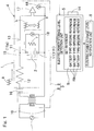
- Fig. 1 is an explanatory diagram showing a circuit configuration of a battery checker according to an embodiment of the present invention by using an electric circuit and blocks.
- a battery checker 1 of the present embodiment includes a voltage application unit 3 configured to apply an AC voltage to a battery 2 to be measured, a ripple voltage measurement unit 4 configured to measure a ripple voltage contained in a terminal voltage of the battery 2, and an electric power storage level detection unit 5 configured to detect an electric power storage level of the battery 2 by comparing the ripple voltage measured by the ripple voltage measurement unit 4 with a set reference R.
- the battery checker 1 includes an electric power storage level notification unit 6 configured to make notification of the electric power storage level detected by the electric power storage level detection unit 5.
- the battery 2 is mounted in a battery mounting device 15, it may be in a stand-alone state.
- the battery mounting device 15 may be any device that has a rechargeable battery 2. Examples thereof include a charging socket for a rechargeable dry battery, an electric vehicle, a smart phone, a personal computer, and a DIY electric tool.
- the voltage application unit 3 includes a transformer 8 that transforms a voltage of an AC power supply 7 to a voltage suitable for checking a voltage of the battery 2, and an output circuit 9 that applies or inputs, to the battery 2, the AC voltage transformed by the transformer 8.
- the voltage suitable for checking the voltage of the battery 2 differs depending on the capacity of the battery 2, it may be a voltage that is higher than the voltage of the fully charged battery 2 by several volts (2 to 3 V) or more, for example.
- the AC power supply 7 is, for example, a single-phase 100V or 200V AC commercial power supply.
- Input terminals 10 such as a plug that is inserted into an outlet (not shown) in the wiring of the AC power supply 7 are provided to an upstream of the transformer 8.
- the output circuit 9 may be configured to output to output terminals 11 which apply, to the battery 2 or the battery mounting device 15, the AC voltage transformed by the transformer 8.
- a current limiting resistor 12 and a capacitor 16 for preventing the passage of the DC voltage of the battery 2 are provided between the output terminals 11, 11 and a secondary coil of the transformer 8 in the output circuit 9.
- the current limiting resistor 12 can be replaced with a resistor having a different resistance value.
- the ripple voltage measurement unit 4 includes an amplifier 17 that includes an operational amplifier or the like, a capacitor 13, and a voltmeter 4a.
- the amplifier 17 is an amplifier that amplifies the voltage between two differential input terminals.
- the output terminal 11 (11p) on the positive electrode side of the battery 2 is connected, via the capacitor 13, to an input terminal of the amplifier 17 on the positive electrode side, and the output terminal 11 (11n) on the negative electrode side of the battery 2 is directly connected to an input terminal of the amplifier 17 on the negative electrode side. Since the capacitor 13 is interposed between the battery 2 and the amplifier 17, the DC voltage of the battery 2 is not applied to the amplifier 17, and only the ripple voltage of the battery 2 is applied to the amplifier 17.
- the ripple voltage amplified by the amplifier 17 in this manner is measured by the voltmeter 4a.
- the voltage between the output terminals 11, 11 of the battery 2 is measured by another voltmeter 18 connected between the output terminals 11.
- the electric power storage level detection unit 5 includes a reference storage unit 19 configured to store, as the set reference R, a plurality of battery type-specific references Ra corresponding to respective types of the battery 2 to be measured, and a reference switching unit 14 configured to switch between the plurality of battery type-specific references Ra.
- the reference storage unit 19 includes an electronic circuit, a microcomputer, or the like that includes a storage device having the set reference R stored therein.
- the reference switching unit 14 includes, for example, an operation device operated by an operator, and a circuit, a program, or the like (each of which is not shown) configured to switch between the battery type-specific references Ra in response to the operation of the operator.
- the set reference R is a reference that is generated as appropriate for indicating an electric power storage level that can be known or obtained from the relationship between the ripple voltage and the internal resistance, it may be a reference directly representing the relationship between the ripple voltage and the electric power storage level, without particularly representing the internal resistance as a resistance value.
- the set reference R may be represented as a curve that indicates the relationship between the ripple voltage and the electric power storage level, or may simply be a value representing a fully charged state as a certain threshold value of the ripple voltage.
- the plurality of battery type-specific references Ra in the set reference R are set, for example, according to the type of battery such as a lead battery, a manganese battery, or a lithium ion battery, according to the voltage varying with the number of stacked cells in the battery 2, or according to both of these.
- the reference switching unit 14 may switch the reference for each use. Alternatively, the reference switching unit 14 may switch the reference once, and thereafter use one battery type-specific reference as a fixed reference, so that the battery checker may be used as a battery checker dedicated to a predetermined battery.
- the electric power storage level notification unit 6 is a unit configured to notify a person or a device of information representing the electric power storage level detected by the electric power storage level detection unit 5, and includes an image display device having a liquid crystal screen that indicates the electric power storage level as an image such as a bar chart, or one or a plurality of lamps that are controlled such that, according to the electric power storage level, the number of lamps that are lit up is changed, or the lamps are switched between a lit-up state, a blinking state, and the like.
- the electric power storage level notification unit 6 may have a function of stopping a charge performed by a charger device (not shown) when the electric power storage level is a fully charged state.
- an alternating current is applied to the battery 2, so that a ripple voltage is generated in the terminal voltage of the battery 2. That is, the application of an alternating current a shown in Fig. 1 to the battery 2 causes generation of a ripple voltage b having a waveform shown in Fig. 1 .
- the fluctuating range that is, the amplitude of the ripple voltage is proportional to an internal resistance r of the battery 2.
- the internal resistance r of the battery 2 decreases as charging progresses. Accordingly, as charging progresses, the ripple voltage b decreases as indicated by a waveform denoted by reference character "b"'.
- the fluctuating range of the terminal voltage of the battery 2 is measured by the ripple voltage measurement unit 4 and the detected ripple voltage is compared with the set reference by the electric power storage level detection unit 5, whereby the electric power storage level of the battery 2 can be accurately detected.
- the electric power storage level of the battery 2 can be accurately detected in this manner, a fully charged state during charging can be detected with high precision, and overcharge during quick charging or the like can be avoided, thereby preventing reduction in the lifespan of the battery 2. Furthermore, the above-described accurate detection of the electric power storage level can be performed with a simple configuration merely including the voltage application unit 3 configured to apply the alternating current, and the ripple voltage measurement unit 4 and the electric power storage level detection unit 5 that have the above-described configurations.
- the voltage application unit 3 in this example includes the transformer 8 that transforms the voltage of the AC power supply 7 and the output circuit 9 that applies, to the battery 2, the voltage transformed by the transformer 8, an AC 100V commercial power supply or the like for general household use or the like can be used as the AC power supply 7. Therefore, the voltage application unit 3 is allowed to have a simple configuration.
- the electric power storage level detection unit 5 includes the plurality of battery type-specific references Ra corresponding to the respective types of the battery 2 to be detected and the reference switching unit 14 for switching between the plurality of the battery type-specific references Ra, so that application to various types of the battery 2 is possible.
Landscapes
- Engineering & Computer Science (AREA)
- Manufacturing & Machinery (AREA)
- Chemical & Material Sciences (AREA)
- Chemical Kinetics & Catalysis (AREA)
- Electrochemistry (AREA)
- General Chemical & Material Sciences (AREA)
- Physics & Mathematics (AREA)
- General Physics & Mathematics (AREA)
- Power Engineering (AREA)
- Charge And Discharge Circuits For Batteries Or The Like (AREA)
- Secondary Cells (AREA)
- Tests Of Electric Status Of Batteries (AREA)
Claims (4)
- Batterieprüfer (1) umfassend:eine Spannungsanlegungseinheit (3), die dafür ausgelegt ist, eine Wechselspannung an einer zu messenden Batterie (2) anzulegen;eine Brummspannungsmesseinheit (4), die dafür ausgelegt ist, eine Brummspannung zu messen, die in einer Anschlussspannung der Batterie (2) enthalten ist; undeine elektrische Energiespeicherniveau-Erfassungseinheit (5), die dafür ausgelegt ist, ein elektrisches Energiespeicherniveau der Batterie (2) zu erfassen,dadurch gekennzeichnet, dass
die elektrische Energiespeicherniveau-Erfassungseinheit (5) dafür ausgelegt ist, das elektrische Energiespeicherniveau der Batterie (2) zu erfassen, indem sie die durch die Brummspannungsmesseinheit (4) gemessene Brummspannung mit einem festgelegten Bezugswert (R) vergleicht. - Batterieprüfer (1) nach Anspruch 1, wobei
die Spannungsanlegungseinheit (3) einen Transformator (8), der dafür ausgelegt ist, eine Spannung einer Wechselstromversorgung (7) in eine für eine Spannung der Batterie (2) geeignete Spannung umzuformen, und eine Ausgangsschaltung (9), die dafür ausgelegt ist, der Batterie (2) die durch den Transformator (8) umgeformte Wechselspannung bereitzustellen, aufweist. - Batterieprüfer (1) nach Anspruch 1 oder 2, wobei
die elektrische Energiespeicherniveau-Erfassungseinheit (5) eine Bezugsspeichereinheit (19), die dafür ausgelegt ist, eine Mehrzahl batterie(2)typspezifischer Bezugswerte (Ra), die den Typen der zu messenden Batterie (2) entsprechen, als den festgelegten Bezugswert (R) zu speichern, und eine Bezugswert-Umschalteinheit (14), die dafür ausgelegt ist, zwischen der Mehrzahl batterie(2)typspezifischer Bezugswerte (Ra) umzuschalten, aufweist. - Batterieprüfer (1) nach einem der Ansprüche 1 bis 3, wobei die Brummspannungsmesseinheit (4) einen Kondensator (13), der mit einem Ausgangsanschluss an einer positiven Elektrodenseite der Batterie (11p) angeschlossen ist, einen Verstärker (17), der dafür ausgelegt ist, eine Spannung zwischen dem Kondensator (13) und einem Anschluss an einer negativen Elektrodenseite der Batterie (11n) zu verstärken, und ein Voltmeter (4a), das dafür ausgelegt ist, eine durch den Verstärker (17) verstärkte Brummspannung zu messen, aufweist.
Applications Claiming Priority (2)
| Application Number | Priority Date | Filing Date | Title |
|---|---|---|---|
| JP2014186347A JP2016057264A (ja) | 2014-09-12 | 2014-09-12 | バッテリーチェッカー |
| PCT/JP2015/074666 WO2016039204A1 (ja) | 2014-09-12 | 2015-08-31 | バッテリーチェッカー |
Publications (3)
| Publication Number | Publication Date |
|---|---|
| EP3193181A1 EP3193181A1 (de) | 2017-07-19 |
| EP3193181A4 EP3193181A4 (de) | 2018-05-16 |
| EP3193181B1 true EP3193181B1 (de) | 2019-06-05 |
Family
ID=55458956
Family Applications (1)
| Application Number | Title | Priority Date | Filing Date |
|---|---|---|---|
| EP15839194.6A Active EP3193181B1 (de) | 2014-09-12 | 2015-08-31 | Batterieprüfer |
Country Status (5)
| Country | Link |
|---|---|
| US (1) | US10459036B2 (de) |
| EP (1) | EP3193181B1 (de) |
| JP (1) | JP2016057264A (de) |
| CN (1) | CN106687816A (de) |
| WO (1) | WO2016039204A1 (de) |
Families Citing this family (4)
| Publication number | Priority date | Publication date | Assignee | Title |
|---|---|---|---|---|
| JP2016057264A (ja) | 2014-09-12 | 2016-04-21 | Ntn株式会社 | バッテリーチェッカー |
| JP6958392B2 (ja) | 2018-01-30 | 2021-11-02 | トヨタ自動車株式会社 | 二次電池システムおよび二次電池の劣化状態推定方法 |
| JP7056449B2 (ja) * | 2018-08-01 | 2022-04-19 | トヨタ自動車株式会社 | 蓄電デバイスの検査装置 |
| US11609274B2 (en) * | 2021-07-08 | 2023-03-21 | Guangzhou Automobile Group Co., Ltd. | Battery state detection device and vehicle device |
Family Cites Families (26)
| Publication number | Priority date | Publication date | Assignee | Title |
|---|---|---|---|---|
| US3350574A (en) * | 1965-01-11 | 1967-10-31 | Bendix Corp | Network for converting a direct current signal into pulses having a frequency corresponding to the amplitude of the direct current signal |
| US4999576A (en) * | 1989-07-31 | 1991-03-12 | General Electric Company | Electrical-energy-supplying device having an extended storage life |
| JPH03293935A (ja) * | 1990-04-10 | 1991-12-25 | Shimadzu Corp | 充電検出装置 |
| JPH0682839A (ja) | 1992-09-04 | 1994-03-25 | Canon Inc | 液晶素子 |
| JPH0682839U (ja) * | 1993-05-12 | 1994-11-25 | サンエー電機株式会社 | 放電灯変圧器点灯回路 |
| JP3379298B2 (ja) * | 1995-08-30 | 2003-02-24 | 新神戸電機株式会社 | シール鉛蓄電池の寿命判定装置 |
| JP3675009B2 (ja) * | 1995-10-27 | 2005-07-27 | 日本電池株式会社 | 交流電源装置 |
| US5751217A (en) * | 1996-02-01 | 1998-05-12 | Motorola, Inc. | Method and apparatus for assessing available battery life in a rechargeable battery |
| JPH09288155A (ja) * | 1996-04-23 | 1997-11-04 | Bell Techno:Kk | バッテリーチェック方法及びバッテリーチェッカー |
| US6885195B2 (en) * | 1996-07-29 | 2005-04-26 | Midtronics, Inc. | Method and apparatus for auditing a battery test |
| JPH10170615A (ja) | 1996-12-10 | 1998-06-26 | Sanko Denki:Kk | 車載バッテリ−チェッカ− |
| JP2000081469A (ja) * | 1998-06-22 | 2000-03-21 | Asahi Optical Co Ltd | バッテリ―の残量チェック装置 |
| US6134391A (en) * | 1998-06-22 | 2000-10-17 | Asahi Kogaku Kogyo Kabushiki Kaisha | Battery residual-power checking apparatus |
| CN1421975A (zh) * | 2001-11-23 | 2003-06-04 | 成都世能科技有限责任公司 | 自适应充电控制芯片 |
| JP2004038029A (ja) | 2002-07-05 | 2004-02-05 | Konica Minolta Holdings Inc | カメラのバッテリー残量管理装置 |
| EP2028503B8 (de) * | 2006-06-09 | 2014-04-09 | The Furukawa Electric Co., Ltd. | Verfahren zur beurteilung des verschlechterungszustands einer batterie, verschlechterungsbeurteilungseinrichtung und stromversorgungssystem |
| CN101183142B (zh) * | 2007-05-15 | 2011-03-16 | 李庆兰 | 蓄电池内阻的在线测量方法及电流工作模块及蓄电池内阻在线测量仪 |
| JP4649489B2 (ja) * | 2008-03-27 | 2011-03-09 | 株式会社日立製作所 | 組電池の総電圧検出回路 |
| US8421416B2 (en) * | 2008-04-16 | 2013-04-16 | Texas Instruments Incorporated | Battery charge compensation |
| JP4862937B2 (ja) * | 2009-12-08 | 2012-01-25 | トヨタ自動車株式会社 | 蓄電装置の内部抵抗推定装置、蓄電装置の劣化判定装置、および電源システム |
| CN102116844B (zh) * | 2009-12-31 | 2014-04-09 | 深圳清华大学研究院 | 测量阀控铅酸蓄电池荷电状态的方法和装置 |
| US20130069660A1 (en) * | 2010-02-17 | 2013-03-21 | Julien Bernard | Method for in situ battery diagnostic by electrochemical impedance spectroscopy |
| JP2013142649A (ja) * | 2012-01-12 | 2013-07-22 | Nissan Motor Co Ltd | 充電状態測定装置 |
| ITRM20120643A1 (it) * | 2012-12-18 | 2014-06-19 | Calbatt S R L | Metodo per la caratterizzazione di accumulatori. |
| CN203643582U (zh) * | 2013-11-21 | 2014-06-11 | 华南理工大学 | 一种基于内阻法的蓄电池剩余电量在线监测系统 |
| JP2016057264A (ja) | 2014-09-12 | 2016-04-21 | Ntn株式会社 | バッテリーチェッカー |
-
2014
- 2014-09-12 JP JP2014186347A patent/JP2016057264A/ja active Pending
-
2015
- 2015-08-31 EP EP15839194.6A patent/EP3193181B1/de active Active
- 2015-08-31 WO PCT/JP2015/074666 patent/WO2016039204A1/ja not_active Ceased
- 2015-08-31 CN CN201580048502.4A patent/CN106687816A/zh active Pending
-
2017
- 2017-03-09 US US15/454,494 patent/US10459036B2/en active Active
Non-Patent Citations (1)
| Title |
|---|
| None * |
Also Published As
| Publication number | Publication date |
|---|---|
| EP3193181A4 (de) | 2018-05-16 |
| WO2016039204A1 (ja) | 2016-03-17 |
| JP2016057264A (ja) | 2016-04-21 |
| CN106687816A (zh) | 2017-05-17 |
| US20170184677A1 (en) | 2017-06-29 |
| US10459036B2 (en) | 2019-10-29 |
| EP3193181A1 (de) | 2017-07-19 |
Similar Documents
| Publication | Publication Date | Title |
|---|---|---|
| US9291681B2 (en) | Monitoring apparatus and method of battery contact point in charge/discharge system with batteries connected in series | |
| US20170187215A1 (en) | Charging device | |
| US11075524B2 (en) | Rapid battery charging | |
| US10459036B2 (en) | Battery checker | |
| JP5620297B2 (ja) | インピーダンス測定装置 | |
| US20180375348A1 (en) | Connectivity check between cells and wiring control electronics with only one switch | |
| WO2015008728A1 (ja) | 電池状態検出装置 | |
| Ningrum | Estimation of state of charge (SoC) using modified coulomb counting method with open circuit compensation for battery management system (BMS) | |
| KR20150052139A (ko) | 절연 결함을 검출 및 측정하기 위한 장치 | |
| WO2016024490A1 (ja) | 充電装置 | |
| EP2571137B1 (de) | Schaltung für eine kleine elektrische Anwendung mit einem Akkumulator und Verfahren zum Messen des Ladestroms | |
| KR101734724B1 (ko) | 전기 자동차의 누전 검출 장치 | |
| JP6865780B2 (ja) | バッテリーチェッカー | |
| CN104577240B (zh) | 具有测量电池的锂离子蓄能器及其特性的确定方法 | |
| Jang et al. | Impedance-based and circuit-parameter-based battery models for HEV power systems | |
| JP2010261807A (ja) | 蓄電池の劣化判定方法、充放電制御装置 | |
| KR101734723B1 (ko) | 전기 자동차의 누전 검출 장치 | |
| Hossain et al. | Battery impedance measurement using electrochemical impedance spectroscopy board | |
| JP2015102443A (ja) | 電池状態検出装置及び電池状態検出方法 | |
| KR101521169B1 (ko) | 완속 충전기 보호시스템 및 그 보호방법 | |
| TW201621336A (zh) | 快速檢測電池其殘餘電量(soc)之裝置 | |
| JP6559521B2 (ja) | バッテリーチェッカー | |
| JP2015033236A (ja) | 電子機器及び電子機器システム | |
| CN106597256B (zh) | 过充、过放电压阈值测试电路 | |
| Mach et al. | Electronics and software structure of BMS with circuits of BQ769x0 series |
Legal Events
| Date | Code | Title | Description |
|---|---|---|---|
| STAA | Information on the status of an ep patent application or granted ep patent |
Free format text: STATUS: THE INTERNATIONAL PUBLICATION HAS BEEN MADE |
|
| PUAI | Public reference made under article 153(3) epc to a published international application that has entered the european phase |
Free format text: ORIGINAL CODE: 0009012 |
|
| STAA | Information on the status of an ep patent application or granted ep patent |
Free format text: STATUS: REQUEST FOR EXAMINATION WAS MADE |
|
| 17P | Request for examination filed |
Effective date: 20170330 |
|
| AK | Designated contracting states |
Kind code of ref document: A1 Designated state(s): AL AT BE BG CH CY CZ DE DK EE ES FI FR GB GR HR HU IE IS IT LI LT LU LV MC MK MT NL NO PL PT RO RS SE SI SK SM TR |
|
| AX | Request for extension of the european patent |
Extension state: BA ME |
|
| DAV | Request for validation of the european patent (deleted) | ||
| DAX | Request for extension of the european patent (deleted) | ||
| A4 | Supplementary search report drawn up and despatched |
Effective date: 20180412 |
|
| RIC1 | Information provided on ipc code assigned before grant |
Ipc: H01M 10/48 20060101ALI20180406BHEP Ipc: G01R 31/36 20060101AFI20180406BHEP Ipc: H01M 10/42 20060101ALI20180406BHEP Ipc: H01M 10/44 20060101ALI20180406BHEP Ipc: H02J 7/00 20060101ALI20180406BHEP |
|
| REG | Reference to a national code |
Ref country code: DE Ref legal event code: R079 Ref document number: 602015031544 Country of ref document: DE Free format text: PREVIOUS MAIN CLASS: G01R0031360000 Ipc: H01M0010420000 |
|
| GRAP | Despatch of communication of intention to grant a patent |
Free format text: ORIGINAL CODE: EPIDOSNIGR1 |
|
| RIC1 | Information provided on ipc code assigned before grant |
Ipc: H01M 10/42 20060101AFI20181212BHEP Ipc: H01M 10/48 20060101ALN20181212BHEP |
|
| STAA | Information on the status of an ep patent application or granted ep patent |
Free format text: STATUS: GRANT OF PATENT IS INTENDED |
|
| INTG | Intention to grant announced |
Effective date: 20190117 |
|
| GRAS | Grant fee paid |
Free format text: ORIGINAL CODE: EPIDOSNIGR3 |
|
| GRAA | (expected) grant |
Free format text: ORIGINAL CODE: 0009210 |
|
| STAA | Information on the status of an ep patent application or granted ep patent |
Free format text: STATUS: THE PATENT HAS BEEN GRANTED |
|
| AK | Designated contracting states |
Kind code of ref document: B1 Designated state(s): AL AT BE BG CH CY CZ DE DK EE ES FI FR GB GR HR HU IE IS IT LI LT LU LV MC MK MT NL NO PL PT RO RS SE SI SK SM TR |
|
| REG | Reference to a national code |
Ref country code: GB Ref legal event code: FG4D |
|
| REG | Reference to a national code |
Ref country code: CH Ref legal event code: EP |
|
| REG | Reference to a national code |
Ref country code: AT Ref legal event code: REF Ref document number: 1140923 Country of ref document: AT Kind code of ref document: T Effective date: 20190615 |
|
| REG | Reference to a national code |
Ref country code: IE Ref legal event code: FG4D |
|
| REG | Reference to a national code |
Ref country code: DE Ref legal event code: R096 Ref document number: 602015031544 Country of ref document: DE |
|
| REG | Reference to a national code |
Ref country code: NL Ref legal event code: MP Effective date: 20190605 |
|
| REG | Reference to a national code |
Ref country code: LT Ref legal event code: MG4D |
|
| PG25 | Lapsed in a contracting state [announced via postgrant information from national office to epo] |
Ref country code: HR Free format text: LAPSE BECAUSE OF FAILURE TO SUBMIT A TRANSLATION OF THE DESCRIPTION OR TO PAY THE FEE WITHIN THE PRESCRIBED TIME-LIMIT Effective date: 20190605 Ref country code: LT Free format text: LAPSE BECAUSE OF FAILURE TO SUBMIT A TRANSLATION OF THE DESCRIPTION OR TO PAY THE FEE WITHIN THE PRESCRIBED TIME-LIMIT Effective date: 20190605 Ref country code: ES Free format text: LAPSE BECAUSE OF FAILURE TO SUBMIT A TRANSLATION OF THE DESCRIPTION OR TO PAY THE FEE WITHIN THE PRESCRIBED TIME-LIMIT Effective date: 20190605 Ref country code: AL Free format text: LAPSE BECAUSE OF FAILURE TO SUBMIT A TRANSLATION OF THE DESCRIPTION OR TO PAY THE FEE WITHIN THE PRESCRIBED TIME-LIMIT Effective date: 20190605 Ref country code: FI Free format text: LAPSE BECAUSE OF FAILURE TO SUBMIT A TRANSLATION OF THE DESCRIPTION OR TO PAY THE FEE WITHIN THE PRESCRIBED TIME-LIMIT Effective date: 20190605 Ref country code: SE Free format text: LAPSE BECAUSE OF FAILURE TO SUBMIT A TRANSLATION OF THE DESCRIPTION OR TO PAY THE FEE WITHIN THE PRESCRIBED TIME-LIMIT Effective date: 20190605 Ref country code: NO Free format text: LAPSE BECAUSE OF FAILURE TO SUBMIT A TRANSLATION OF THE DESCRIPTION OR TO PAY THE FEE WITHIN THE PRESCRIBED TIME-LIMIT Effective date: 20190905 |
|
| PG25 | Lapsed in a contracting state [announced via postgrant information from national office to epo] |
Ref country code: GR Free format text: LAPSE BECAUSE OF FAILURE TO SUBMIT A TRANSLATION OF THE DESCRIPTION OR TO PAY THE FEE WITHIN THE PRESCRIBED TIME-LIMIT Effective date: 20190906 Ref country code: LV Free format text: LAPSE BECAUSE OF FAILURE TO SUBMIT A TRANSLATION OF THE DESCRIPTION OR TO PAY THE FEE WITHIN THE PRESCRIBED TIME-LIMIT Effective date: 20190605 Ref country code: RS Free format text: LAPSE BECAUSE OF FAILURE TO SUBMIT A TRANSLATION OF THE DESCRIPTION OR TO PAY THE FEE WITHIN THE PRESCRIBED TIME-LIMIT Effective date: 20190605 Ref country code: BG Free format text: LAPSE BECAUSE OF FAILURE TO SUBMIT A TRANSLATION OF THE DESCRIPTION OR TO PAY THE FEE WITHIN THE PRESCRIBED TIME-LIMIT Effective date: 20190905 |
|
| REG | Reference to a national code |
Ref country code: AT Ref legal event code: MK05 Ref document number: 1140923 Country of ref document: AT Kind code of ref document: T Effective date: 20190605 |
|
| PG25 | Lapsed in a contracting state [announced via postgrant information from national office to epo] |
Ref country code: AT Free format text: LAPSE BECAUSE OF FAILURE TO SUBMIT A TRANSLATION OF THE DESCRIPTION OR TO PAY THE FEE WITHIN THE PRESCRIBED TIME-LIMIT Effective date: 20190605 Ref country code: EE Free format text: LAPSE BECAUSE OF FAILURE TO SUBMIT A TRANSLATION OF THE DESCRIPTION OR TO PAY THE FEE WITHIN THE PRESCRIBED TIME-LIMIT Effective date: 20190605 Ref country code: RO Free format text: LAPSE BECAUSE OF FAILURE TO SUBMIT A TRANSLATION OF THE DESCRIPTION OR TO PAY THE FEE WITHIN THE PRESCRIBED TIME-LIMIT Effective date: 20190605 Ref country code: NL Free format text: LAPSE BECAUSE OF FAILURE TO SUBMIT A TRANSLATION OF THE DESCRIPTION OR TO PAY THE FEE WITHIN THE PRESCRIBED TIME-LIMIT Effective date: 20190605 Ref country code: CZ Free format text: LAPSE BECAUSE OF FAILURE TO SUBMIT A TRANSLATION OF THE DESCRIPTION OR TO PAY THE FEE WITHIN THE PRESCRIBED TIME-LIMIT Effective date: 20190605 Ref country code: PT Free format text: LAPSE BECAUSE OF FAILURE TO SUBMIT A TRANSLATION OF THE DESCRIPTION OR TO PAY THE FEE WITHIN THE PRESCRIBED TIME-LIMIT Effective date: 20191007 Ref country code: SK Free format text: LAPSE BECAUSE OF FAILURE TO SUBMIT A TRANSLATION OF THE DESCRIPTION OR TO PAY THE FEE WITHIN THE PRESCRIBED TIME-LIMIT Effective date: 20190605 |
|
| PG25 | Lapsed in a contracting state [announced via postgrant information from national office to epo] |
Ref country code: IS Free format text: LAPSE BECAUSE OF FAILURE TO SUBMIT A TRANSLATION OF THE DESCRIPTION OR TO PAY THE FEE WITHIN THE PRESCRIBED TIME-LIMIT Effective date: 20191005 Ref country code: SM Free format text: LAPSE BECAUSE OF FAILURE TO SUBMIT A TRANSLATION OF THE DESCRIPTION OR TO PAY THE FEE WITHIN THE PRESCRIBED TIME-LIMIT Effective date: 20190605 Ref country code: IT Free format text: LAPSE BECAUSE OF FAILURE TO SUBMIT A TRANSLATION OF THE DESCRIPTION OR TO PAY THE FEE WITHIN THE PRESCRIBED TIME-LIMIT Effective date: 20190605 |
|
| REG | Reference to a national code |
Ref country code: DE Ref legal event code: R097 Ref document number: 602015031544 Country of ref document: DE |
|
| PG25 | Lapsed in a contracting state [announced via postgrant information from national office to epo] |
Ref country code: TR Free format text: LAPSE BECAUSE OF FAILURE TO SUBMIT A TRANSLATION OF THE DESCRIPTION OR TO PAY THE FEE WITHIN THE PRESCRIBED TIME-LIMIT Effective date: 20190605 |
|
| PLBE | No opposition filed within time limit |
Free format text: ORIGINAL CODE: 0009261 |
|
| STAA | Information on the status of an ep patent application or granted ep patent |
Free format text: STATUS: NO OPPOSITION FILED WITHIN TIME LIMIT |
|
| PG25 | Lapsed in a contracting state [announced via postgrant information from national office to epo] |
Ref country code: DK Free format text: LAPSE BECAUSE OF FAILURE TO SUBMIT A TRANSLATION OF THE DESCRIPTION OR TO PAY THE FEE WITHIN THE PRESCRIBED TIME-LIMIT Effective date: 20190605 Ref country code: PL Free format text: LAPSE BECAUSE OF FAILURE TO SUBMIT A TRANSLATION OF THE DESCRIPTION OR TO PAY THE FEE WITHIN THE PRESCRIBED TIME-LIMIT Effective date: 20190605 |
|
| 26N | No opposition filed |
Effective date: 20200306 |
|
| PG25 | Lapsed in a contracting state [announced via postgrant information from national office to epo] |
Ref country code: CH Free format text: LAPSE BECAUSE OF NON-PAYMENT OF DUE FEES Effective date: 20190831 Ref country code: LI Free format text: LAPSE BECAUSE OF NON-PAYMENT OF DUE FEES Effective date: 20190831 Ref country code: LU Free format text: LAPSE BECAUSE OF NON-PAYMENT OF DUE FEES Effective date: 20190831 Ref country code: MC Free format text: LAPSE BECAUSE OF FAILURE TO SUBMIT A TRANSLATION OF THE DESCRIPTION OR TO PAY THE FEE WITHIN THE PRESCRIBED TIME-LIMIT Effective date: 20190605 Ref country code: SI Free format text: LAPSE BECAUSE OF FAILURE TO SUBMIT A TRANSLATION OF THE DESCRIPTION OR TO PAY THE FEE WITHIN THE PRESCRIBED TIME-LIMIT Effective date: 20190605 |
|
| REG | Reference to a national code |
Ref country code: BE Ref legal event code: MM Effective date: 20190831 |
|
| PG25 | Lapsed in a contracting state [announced via postgrant information from national office to epo] |
Ref country code: IE Free format text: LAPSE BECAUSE OF NON-PAYMENT OF DUE FEES Effective date: 20190831 |
|
| PG25 | Lapsed in a contracting state [announced via postgrant information from national office to epo] |
Ref country code: BE Free format text: LAPSE BECAUSE OF NON-PAYMENT OF DUE FEES Effective date: 20190831 |
|
| GBPC | Gb: european patent ceased through non-payment of renewal fee |
Effective date: 20190905 |
|
| PG25 | Lapsed in a contracting state [announced via postgrant information from national office to epo] |
Ref country code: GB Free format text: LAPSE BECAUSE OF NON-PAYMENT OF DUE FEES Effective date: 20190905 |
|
| PG25 | Lapsed in a contracting state [announced via postgrant information from national office to epo] |
Ref country code: CY Free format text: LAPSE BECAUSE OF FAILURE TO SUBMIT A TRANSLATION OF THE DESCRIPTION OR TO PAY THE FEE WITHIN THE PRESCRIBED TIME-LIMIT Effective date: 20190605 |
|
| PG25 | Lapsed in a contracting state [announced via postgrant information from national office to epo] |
Ref country code: HU Free format text: LAPSE BECAUSE OF FAILURE TO SUBMIT A TRANSLATION OF THE DESCRIPTION OR TO PAY THE FEE WITHIN THE PRESCRIBED TIME-LIMIT; INVALID AB INITIO Effective date: 20150831 Ref country code: MT Free format text: LAPSE BECAUSE OF FAILURE TO SUBMIT A TRANSLATION OF THE DESCRIPTION OR TO PAY THE FEE WITHIN THE PRESCRIBED TIME-LIMIT Effective date: 20190605 |
|
| PG25 | Lapsed in a contracting state [announced via postgrant information from national office to epo] |
Ref country code: MK Free format text: LAPSE BECAUSE OF FAILURE TO SUBMIT A TRANSLATION OF THE DESCRIPTION OR TO PAY THE FEE WITHIN THE PRESCRIBED TIME-LIMIT Effective date: 20190605 |
|
| PGFP | Annual fee paid to national office [announced via postgrant information from national office to epo] |
Ref country code: DE Payment date: 20250702 Year of fee payment: 11 |
|
| PGFP | Annual fee paid to national office [announced via postgrant information from national office to epo] |
Ref country code: FR Payment date: 20250703 Year of fee payment: 11 |