EP3194202B1 - Dispositif motorisé de puissance à réglage rapide - Google Patents
Dispositif motorisé de puissance à réglage rapide Download PDFInfo
- Publication number
- EP3194202B1 EP3194202B1 EP15775543.0A EP15775543A EP3194202B1 EP 3194202 B1 EP3194202 B1 EP 3194202B1 EP 15775543 A EP15775543 A EP 15775543A EP 3194202 B1 EP3194202 B1 EP 3194202B1
- Authority
- EP
- European Patent Office
- Prior art keywords
- assembly
- track
- driven
- drive
- gear
- Prior art date
- Legal status (The legal status is an assumption and is not a legal conclusion. Google has not performed a legal analysis and makes no representation as to the accuracy of the status listed.)
- Active
Links
Images


Classifications
-
- B—PERFORMING OPERATIONS; TRANSPORTING
- B60—VEHICLES IN GENERAL
- B60N—SEATS SPECIALLY ADAPTED FOR VEHICLES; VEHICLE PASSENGER ACCOMMODATION NOT OTHERWISE PROVIDED FOR
- B60N2/00—Seats specially adapted for vehicles; Arrangement or mounting of seats in vehicles
- B60N2/02—Seats specially adapted for vehicles; Arrangement or mounting of seats in vehicles the seat or part thereof being movable, e.g. adjustable
- B60N2/04—Seats specially adapted for vehicles; Arrangement or mounting of seats in vehicles the seat or part thereof being movable, e.g. adjustable the whole seat being movable
- B60N2/06—Seats specially adapted for vehicles; Arrangement or mounting of seats in vehicles the seat or part thereof being movable, e.g. adjustable the whole seat being movable slidable
- B60N2/07—Slide construction
- B60N2/0702—Slide construction characterised by its cross-section
- B60N2/0715—C or U-shaped
-
- B—PERFORMING OPERATIONS; TRANSPORTING
- B60—VEHICLES IN GENERAL
- B60N—SEATS SPECIALLY ADAPTED FOR VEHICLES; VEHICLE PASSENGER ACCOMMODATION NOT OTHERWISE PROVIDED FOR
- B60N2/00—Seats specially adapted for vehicles; Arrangement or mounting of seats in vehicles
- B60N2/005—Arrangement or mounting of seats in vehicles, e.g. dismountable auxiliary seats
- B60N2/015—Attaching seats directly to vehicle chassis
- B60N2/01508—Attaching seats directly to vehicle chassis using quick release attachments
- B60N2/01516—Attaching seats directly to vehicle chassis using quick release attachments with locking mechanisms
- B60N2/0155—Attaching seats directly to vehicle chassis using quick release attachments with locking mechanisms with the locking mechanism on the vehicle floor or rail
-
- B—PERFORMING OPERATIONS; TRANSPORTING
- B60—VEHICLES IN GENERAL
- B60N—SEATS SPECIALLY ADAPTED FOR VEHICLES; VEHICLE PASSENGER ACCOMMODATION NOT OTHERWISE PROVIDED FOR
- B60N2/00—Seats specially adapted for vehicles; Arrangement or mounting of seats in vehicles
- B60N2/02—Seats specially adapted for vehicles; Arrangement or mounting of seats in vehicles the seat or part thereof being movable, e.g. adjustable
- B60N2/0224—Non-manual adjustments, e.g. with electrical operation
- B60N2/02246—Electric motors therefor
- B60N2/02253—Electric motors therefor characterised by the transmission between the electric motor and the seat or seat parts
-
- B—PERFORMING OPERATIONS; TRANSPORTING
- B60—VEHICLES IN GENERAL
- B60N—SEATS SPECIALLY ADAPTED FOR VEHICLES; VEHICLE PASSENGER ACCOMMODATION NOT OTHERWISE PROVIDED FOR
- B60N2/00—Seats specially adapted for vehicles; Arrangement or mounting of seats in vehicles
- B60N2/02—Seats specially adapted for vehicles; Arrangement or mounting of seats in vehicles the seat or part thereof being movable, e.g. adjustable
- B60N2/0224—Non-manual adjustments, e.g. with electrical operation
- B60N2/02246—Electric motors therefor
- B60N2/02258—Electric motors therefor characterised by the mounting of the electric motor for adjusting the seat
-
- B—PERFORMING OPERATIONS; TRANSPORTING
- B60—VEHICLES IN GENERAL
- B60N—SEATS SPECIALLY ADAPTED FOR VEHICLES; VEHICLE PASSENGER ACCOMMODATION NOT OTHERWISE PROVIDED FOR
- B60N2/00—Seats specially adapted for vehicles; Arrangement or mounting of seats in vehicles
- B60N2/02—Seats specially adapted for vehicles; Arrangement or mounting of seats in vehicles the seat or part thereof being movable, e.g. adjustable
- B60N2/04—Seats specially adapted for vehicles; Arrangement or mounting of seats in vehicles the seat or part thereof being movable, e.g. adjustable the whole seat being movable
- B60N2/06—Seats specially adapted for vehicles; Arrangement or mounting of seats in vehicles the seat or part thereof being movable, e.g. adjustable the whole seat being movable slidable
- B60N2/067—Seats specially adapted for vehicles; Arrangement or mounting of seats in vehicles the seat or part thereof being movable, e.g. adjustable the whole seat being movable slidable by linear actuators, e.g. linear screw mechanisms
-
- B—PERFORMING OPERATIONS; TRANSPORTING
- B60—VEHICLES IN GENERAL
- B60N—SEATS SPECIALLY ADAPTED FOR VEHICLES; VEHICLE PASSENGER ACCOMMODATION NOT OTHERWISE PROVIDED FOR
- B60N2/00—Seats specially adapted for vehicles; Arrangement or mounting of seats in vehicles
- B60N2/02—Seats specially adapted for vehicles; Arrangement or mounting of seats in vehicles the seat or part thereof being movable, e.g. adjustable
- B60N2/04—Seats specially adapted for vehicles; Arrangement or mounting of seats in vehicles the seat or part thereof being movable, e.g. adjustable the whole seat being movable
- B60N2/06—Seats specially adapted for vehicles; Arrangement or mounting of seats in vehicles the seat or part thereof being movable, e.g. adjustable the whole seat being movable slidable
- B60N2/08—Seats specially adapted for vehicles; Arrangement or mounting of seats in vehicles the seat or part thereof being movable, e.g. adjustable the whole seat being movable slidable characterised by the locking device
- B60N2/0831—Movement of the latch
- B60N2/0862—Movement of the latch sliding
- B60N2/0875—Movement of the latch sliding in a vertical direction
-
- B—PERFORMING OPERATIONS; TRANSPORTING
- B60—VEHICLES IN GENERAL
- B60N—SEATS SPECIALLY ADAPTED FOR VEHICLES; VEHICLE PASSENGER ACCOMMODATION NOT OTHERWISE PROVIDED FOR
- B60N2/00—Seats specially adapted for vehicles; Arrangement or mounting of seats in vehicles
- B60N2/02—Seats specially adapted for vehicles; Arrangement or mounting of seats in vehicles the seat or part thereof being movable, e.g. adjustable
- B60N2/04—Seats specially adapted for vehicles; Arrangement or mounting of seats in vehicles the seat or part thereof being movable, e.g. adjustable the whole seat being movable
- B60N2/12—Seats specially adapted for vehicles; Arrangement or mounting of seats in vehicles the seat or part thereof being movable, e.g. adjustable the whole seat being movable slidable and tiltable
- B60N2/123—Seats specially adapted for vehicles; Arrangement or mounting of seats in vehicles the seat or part thereof being movable, e.g. adjustable the whole seat being movable slidable and tiltable and provided with memory locks
-
- B—PERFORMING OPERATIONS; TRANSPORTING
- B60—VEHICLES IN GENERAL
- B60N—SEATS SPECIALLY ADAPTED FOR VEHICLES; VEHICLE PASSENGER ACCOMMODATION NOT OTHERWISE PROVIDED FOR
- B60N2/00—Seats specially adapted for vehicles; Arrangement or mounting of seats in vehicles
- B60N2/02—Seats specially adapted for vehicles; Arrangement or mounting of seats in vehicles the seat or part thereof being movable, e.g. adjustable
- B60N2/04—Seats specially adapted for vehicles; Arrangement or mounting of seats in vehicles the seat or part thereof being movable, e.g. adjustable the whole seat being movable
- B60N2/06—Seats specially adapted for vehicles; Arrangement or mounting of seats in vehicles the seat or part thereof being movable, e.g. adjustable the whole seat being movable slidable
- B60N2/07—Slide construction
-
- B—PERFORMING OPERATIONS; TRANSPORTING
- B60—VEHICLES IN GENERAL
- B60N—SEATS SPECIALLY ADAPTED FOR VEHICLES; VEHICLE PASSENGER ACCOMMODATION NOT OTHERWISE PROVIDED FOR
- B60N2/00—Seats specially adapted for vehicles; Arrangement or mounting of seats in vehicles
- B60N2/02—Seats specially adapted for vehicles; Arrangement or mounting of seats in vehicles the seat or part thereof being movable, e.g. adjustable
- B60N2/04—Seats specially adapted for vehicles; Arrangement or mounting of seats in vehicles the seat or part thereof being movable, e.g. adjustable the whole seat being movable
- B60N2/06—Seats specially adapted for vehicles; Arrangement or mounting of seats in vehicles the seat or part thereof being movable, e.g. adjustable the whole seat being movable slidable
- B60N2/08—Seats specially adapted for vehicles; Arrangement or mounting of seats in vehicles the seat or part thereof being movable, e.g. adjustable the whole seat being movable slidable characterised by the locking device
-
- F—MECHANICAL ENGINEERING; LIGHTING; HEATING; WEAPONS; BLASTING
- F16—ENGINEERING ELEMENTS AND UNITS; GENERAL MEASURES FOR PRODUCING AND MAINTAINING EFFECTIVE FUNCTIONING OF MACHINES OR INSTALLATIONS; THERMAL INSULATION IN GENERAL
- F16H—GEARING
- F16H25/00—Gearings comprising primarily only cams, cam-followers and screw-and-nut mechanisms
- F16H25/18—Gearings comprising primarily only cams, cam-followers and screw-and-nut mechanisms for conveying or interconverting oscillating or reciprocating motions
- F16H25/20—Screw mechanisms
- F16H2025/2062—Arrangements for driving the actuator
- F16H2025/2071—Disconnecting drive source from the actuator, e.g. using clutches for release of drive connection during manual control
-
- F—MECHANICAL ENGINEERING; LIGHTING; HEATING; WEAPONS; BLASTING
- F16—ENGINEERING ELEMENTS AND UNITS; GENERAL MEASURES FOR PRODUCING AND MAINTAINING EFFECTIVE FUNCTIONING OF MACHINES OR INSTALLATIONS; THERMAL INSULATION IN GENERAL
- F16H—GEARING
- F16H25/00—Gearings comprising primarily only cams, cam-followers and screw-and-nut mechanisms
- F16H25/18—Gearings comprising primarily only cams, cam-followers and screw-and-nut mechanisms for conveying or interconverting oscillating or reciprocating motions
- F16H25/20—Screw mechanisms
- F16H2025/2062—Arrangements for driving the actuator
- F16H2025/209—Arrangements for driving the actuator using worm gears
Definitions
- the invention relates to a quick adjust power adjuster for a seat track for an automotive vehicle seat assembly. More particularly, the invention relates to quick adjust power adjuster having a manual disconnect mechanism for selectively providing both powered and manual fore and aft movement of the seat assembly along a floor of an automotive vehicle.
- Automotive vehicles include seat assemblies for supporting seat occupants within a passenger compartment of the vehicle.
- seat assemblies include a generally horizontal seat cushion spaced above a floor of the vehicle and a generally vertical or upright seat back.
- the seat back is commonly operatively coupled to the seat cushion to allow for selective pivotal adjustment of the seat back relative to the seat cushion between a plurality of reclined seating positions.
- Many seat assemblies also include a seat track assembly coupled between the seat cushion and the floor to provide fore and aft movement of the seat assembly within the vehicle.
- the seat track assembly includes a lower track fixedly secured to the floor of the vehicle and an upper track slidably engaging the lower track.
- the upper track is fixedly secured to a bottom surface of the seat cushion to allow for sliding movement of the seat assembly along the lower track.
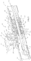
- a seat track assembly 10 is generally shown in Figures 1 and 2 for providing both power and manual sliding fore and aft movement of a seat assembly (not shown) in an automotive vehicle (not shown).
- the seat track assembly 10 extends longitudinally between opposite fore and aft ends 12, 14 and includes a generally inverted U-shaped upper track 16 slidably and matingly coupled to a generally U-shaped lower track 18 for providing fore and aft sliding movement of the upper track 16 relative to the lower track 18, as is commonly known in the art.
- the upper track 16 is adapted to be fixedly secured to the bottom side of a seat cushion assembly of the seat assembly and the lower track 18 is adapted to be fixedly secured to the floor of the automotive vehicle.
- the upper and lower tracks 16, 18 define a longitudinal internal channel 20 therebeween extending between the fore and aft ends 12, 14.
- a threaded lead screw 22 is disposed longitudinally within the channel 20 and extends between a first end 24 and a second end 26.
- the first and second ends 24, 26 of the lead screw 22 are fixedly secured to the lower track 18 at the respective fore and aft ends thereof by L-shaped brackets 28.
- the seat track assembly 10 is shown in a fore/aft seat adjusted position for seat occupant comfort in Figures 6 and 7 .
- the release mechanism 36 of the power adjuster 30 is in the locked condition with the locking pin 116 extending through the vertically aligned holes 100, 102 thereby inter-coupling or connecting the driven assembly 34 and drive assembly 32.
- the driven assembly 34 is also coupled to the upper track 16.
- the coupling of the driven assembly 34 and drive assembly 32 further includes meshed engagement between the face gear end 82 of driven face gear 78 with opposing face gear end 52 of drive face gear 48 as shown in Figure 7 .
- the electric motor may be actuated to rotate the worm gear 44 of the drive assembly 32 is first or second rotational directions as is commonly known in the art. It should be appreciated that the electric motor may have an output drive shaft connected directly to the worm gear 44 or have a cable or other flexible shaft extending between and interconnecting the output shaft of the electric motor with the worm gear 44. Rotation of the worm gear 44 is a first rotational direction causes rotation of the drive face gear 48. The meshed engagement of the face gear end 52 of the drive face gear 48 with the face gear end 82 of the driven face gear 78 transfers the rotation of the drive face gear 48 to the driven face gear 78.
- the release mechanism 36 is shown in the unlocked condition with the locking pin 116 raised vertically by the release lever 112 to remove the locking pin 116 from the hole 102 in the top portion 98 of the support strap 90 thereby decoupling the driven assembly 34 from the upper track 16.
- the driven assembly 34 is also decoupled from the drive assembly 32 such that the driven face gear 78 is free to separate from the meshed engagement with the drive face gear 48.
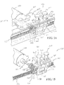
- the drive assembly 122 includes a threaded worm gear 130 seated laterally within the channel 20 between opposite end bushings 132, 134 for rotatable supporting the worm gear 130 within the channel 20 of the upper track 16.
- An electric motor 136 is operatively coupled to the worm gear 130 by an output shaft 138 for rotating the worm gear 130 is opposite rotational directions in the power operation mode.
- a support bracket 140 fixedly secures and supports the electric motor 136 on the upper track 16 and includes a top plate 142 having a pair of holes 144, 146 extending through the top plate 142 and upper track 16.
- the driven assembly 124 includes a housing 150 having a longitudinal through bore 152.
- a drive nut 154 is rotatable supported in the bore 152 and extends between a distal end 156 and an opposite driven end defined by a toothed worm wheel 158 projecting from the longitudinal end of the housing 150.
- the drive nut 154 is threaded onto the lead screw 22 for fore and aft movement along the longitudinal length of the lead screw 22 in response to rotation of the drive nut 154.
- the distal ends of the teeth 160 of the worm wheel 158 have a leading dual chamfer 162 for facilitating engagement with threads 148 of the worm gear 130 during connecting in the power operation mode as will be further discussed below.
- the housing 150 further includes a pair of spaced apart bores 164, 166 in the top portion thereof for selective axial alignment with the holes 144, 146 in the support bracket 140.
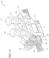
- the electric motor 136 may be actuated to rotate the worm gear 130 of the drive assembly 122 in first or second rotational directions to cause rotation of the worm wheel 158.
- the drive nut 154 rotates from the rotational force on the worm wheel 158 and causes the driven assembly 124 to travel longitudinally along the lead screw 22 between the first and second ends 24, 26 thereof in response to rotation of the worm gear 130. Since the driven assembly 124 is coupled to the upper track 16 by the release mechanism 126 in the locked condition, the driven assembly 124 forces the upper track 16 to move longitudinally fore and aft along the lower track 18 in the power operation mode for seat occupant adjustment of the seat track assembly 10 and vehicle seat within the vehicle.
- the release mechanism 126 is in the unlocked position with the locking pins 168, 170 raised vertically and removed from the bores 164, 166 in the housing 150 of the driven assembly 124 thereby decoupling the driven assembly 124 from the upper track 16.
- the drive assembly 122 is also free to separate or de-coupled from the driven assembly 124.
- the driven assembly 124 decoupled from the upper track 16 referred to as the manual operation mode
- the upper track 16 is free to move longitudinally fore and aft along the lower track 18 manually without actuation of the electric motor 136 or drive assembly 122 from the seat adjusted position to the easy entry position.
Landscapes
- Engineering & Computer Science (AREA)
- Aviation & Aerospace Engineering (AREA)
- Transportation (AREA)
- Mechanical Engineering (AREA)
- Seats For Vehicles (AREA)
Claims (10)
- Dispositif d'ajustement motorisé (30) pour ajuster la position d'une première glissière (16) par rapport à une seconde glissière (18) d'un assemblage de glissières pour siège (10), comprenant :une vis d'entraînement (22) adaptée à être attachée de manière fixe sur ladite seconde glissière (18) ;un ensemble menant (32) capable d'être couplé en fonctionnement à ladite première glissière (16) et d'être couplé sélectivement à ladite vis d'entraînement (22) ;un ensemble mené (34) couplé en fonctionnement à ladite vis d'entraînement (22) et sélectivement couplé audit ensemble menant (32) ; etun mécanisme de libération (36) capable d'être couplé à ladite première glissière (16) et d'être actionné entre une condition bloquée en couplant ledit ensemble mené (34) audit ensemble menant (32) et à ladite première glissière (16), de sorte que ledit ensemble mené (34) et ledit ensemble menant (32) se déplacent longitudinalement le long de ladite vis d'entraînement (22) conjointement avec ladite première glissière (16) par rapport à ladite seconde glissière (18), et une condition débloquée dans laquelle ledit ensemble mené (34) est capable d'être découplé vis-à-vis de ladite première glissière (16) et retenu le long de ladite vis d'entraînement (22) pendant un mouvement de ladite première glissière (16) par rapport à ladite seconde glissière (18).
- Dispositif d'ajustement motorisé (30) selon la revendication 1, dans lequel ledit ensemble menant (32) inclut un engrenage menant (48) et ledit ensemble mené (34) inclut un engrenage mené (78) en engagement d'engrènement avec ledit engrenage menant (48) quand ledit mécanisme de libération (36) est dans ladite condition bloquée, de sorte que ledit ensemble mené (34) se déplace longitudinalement le long de ladite vis d'entraînement (22) en réponse à une rotation dudit engrenage menant (48) dans un mode de fonctionnement motorisé.
- Dispositif d'ajustement motorisé (30) selon la revendication 2, dans lequel ledit mécanisme de libération (36) inclut une broche de blocage (116) actionnée par ledit mécanisme de libération (36) entre ladite condition bloquée en engagement avec ledit ensemble mené (34) pour coupler ledit ensemble mené (34) avec ladite première glissière (16) et ledit ensemble menant (32), et ladite condition débloquée dégagée vis-à-vis dudit ensemble mené (34) pour découpler ledit ensemble mené (34) vis-à-vis de ladite première glissière (16) et permettant une séparation dudit ensemble mené (34) vis-à-vis dudit ensemble menant (32).
- Dispositif d'ajustement motorisé (30) selon la revendication 3, incluant en outre un moteur fonctionnellement couplé audit ensemble menant (32) pour mettre en rotation ledit engrenage menant (48), et entraînant de façon sélective ledit ensemble mené (34) longitudinalement le long de ladite vis d'entraînement (22) dans ledit mode de fonctionnement motorisé.
- Dispositif d'ajustement motorisé (30) selon la revendication 4, dans lequel ledit ensemble mené (34) inclut un boîtier (74) ayant un perçage (76) qui le traverse afin de supporter en rotation ledit engrenage mené (78) et dans lequel ladite vis d'entraînement (22) s'étend longitudinalement à travers ledit engrenage mené (78) et ledit perçage (76) dudit boîtier (74).
- Dispositif d'ajustement motorisé (30) selon la revendication 5, dans lequel ledit ensemble menant (32) inclut un boîtier (38) ayant un perçage latéral (40) qui le traverse afin de supporter en rotation une vis sans fin (44) et un perçage longitudinal (46) qui le traverse en recoupant ledit perçage latéral (40) afin de supporter en rotation ledit engrenage menant (48), dans lequel ladite vis sans fin (44) est en engagement d'engrènement avec ledit engrenage menant (48).
- Dispositif d'ajustement motorisé (30) selon la revendication 6, dans lequel ledit ensemble menant (32) inclut une patte de retenue (60) afin de supporter ledit boîtier (38), ladite patte de retenue (60) incluant des portions dressées (62, 64) espacées les unes des autres qui sont interconnectées par une portion de fond (66) et une portion de sommet (68) s'étendant depuis chaque portion dressée attachée de manière fixe à ladite première glissière (16).
- Dispositif d'ajustement motorisé (30) selon la revendication 7, dans lequel ledit ensemble mené (34) inclut une patte de support (90) pour supporter ledit boîtier (74), ladite patte de support (90) incluant des portions dressées (92, 94) espacées les unes des autres qui sont interconnectés par une portion de fond (96) et une portion de sommet (98) qui chevauche une portion supérieure (68) de ladite patte de retenue (60) dans ledit mode de fonctionnement motorisé.
- Dispositif d'ajustement motorisé (30) selon la revendication 8, dans lequel chacune desdites portions de sommet (68, 98) de ladite patte de retenue (60) et de ladite patte de support (90) inclut un trou traversant (100, 102) axialement alignés dans ledit mode de fonctionnement motorisé afin de recevoir ladite broche de blocage (116) à travers ceux-ci dans ladite condition bloquée afin de coupler ledit ensemble mené (34) audit ensemble menant (32).
- Dispositif d'ajustement motorisé (30) selon la revendication 9, dans lequel ledit engrenage menant (98) inclut une extrémité (52) en forme d'engrenage à face dentée et ledit engrenage mené (78) inclut une extrémité en forme d'engrenage à face dentée (82) opposée en engrènement avec ladite extrémité en forme d'engrenage à face dentée (52) dudit engrenage menant (48) dans ledit mode de fonctionnement motorisé afin de transférer une rotation dudit engrenage menant (48) audit engrenage mené (78).
Applications Claiming Priority (3)
| Application Number | Priority Date | Filing Date | Title |
|---|---|---|---|
| US201462052638P | 2014-09-19 | 2014-09-19 | |
| US201562103719P | 2015-01-15 | 2015-01-15 | |
| PCT/US2015/051238 WO2016044841A1 (fr) | 2014-09-19 | 2015-09-21 | Dispositif de réglage de puissance à réglage rapide |
Publications (2)
| Publication Number | Publication Date |
|---|---|
| EP3194202A1 EP3194202A1 (fr) | 2017-07-26 |
| EP3194202B1 true EP3194202B1 (fr) | 2019-05-22 |
Family
ID=54256835
Family Applications (1)
| Application Number | Title | Priority Date | Filing Date |
|---|---|---|---|
| EP15775543.0A Active EP3194202B1 (fr) | 2014-09-19 | 2015-09-21 | Dispositif motorisé de puissance à réglage rapide |
Country Status (5)
| Country | Link |
|---|---|
| US (1) | US10363838B2 (fr) |
| EP (1) | EP3194202B1 (fr) |
| CN (1) | CN107087405B (fr) |
| CA (1) | CA2961769C (fr) |
| WO (1) | WO2016044841A1 (fr) |
Families Citing this family (23)
| Publication number | Priority date | Publication date | Assignee | Title |
|---|---|---|---|---|
| US11766956B2 (en) * | 2016-09-08 | 2023-09-26 | Fisher & Company, Incorporated | Open architecture power length adjuster assembly for a vehicle seat and method of manufacturing the same |
| DE102016224512A1 (de) * | 2016-12-08 | 2018-06-14 | Brose Fahrzeugteile Gmbh & Co. Kg, Coburg | Fahrzeugsitzanordnung mit einer bodenschienenseitig angeordneten Antriebseinrichtung |
| GB2563286B (en) | 2017-06-09 | 2019-11-20 | Ford Global Tech Llc | A motor vehicle seating system with increased flexibility of seating arrangements |
| GB2567521B (en) * | 2017-06-09 | 2020-04-01 | Ford Global Tech Llc | A motor vehicle seating system with increased flexibility of vehicle seating arrangements |
| ES2844673T3 (es) * | 2017-12-04 | 2021-07-22 | Ims Gear Se & Co Kgaa | Unidad de ajuste longitudinal de un asiento, en particular de un asiento en un vehículo de motor |
| US11506272B2 (en) * | 2020-02-21 | 2022-11-22 | Lear Corporation | Track system with a support member |
| EP3844020B1 (fr) * | 2018-10-19 | 2023-08-23 | Magna Seating Inc. | Siège amovible utilisé avec un ensemble rail long |
| US10857913B2 (en) * | 2019-01-10 | 2020-12-08 | Ford Global Technologies, Llc | Vehicle seating assembly |
| US11760233B2 (en) | 2019-02-20 | 2023-09-19 | Fisher & Company, Incorporated | Ultra-compact power length adjuster with anti-back drive capability and pinion-rack output for a vehicle seat |
| TWM582551U (zh) * | 2019-05-27 | 2019-08-21 | 第一傳動科技股份有限公司 | Actuator with both hand and anti-pinch mechanism |
| CN110103785B (zh) * | 2019-06-18 | 2024-01-16 | 湖北航嘉麦格纳座椅系统有限公司 | 一种车辆座椅的电动滑轨及滑轨总成 |
| JP7319142B2 (ja) * | 2019-08-28 | 2023-08-01 | 株式会社Tf-Metal | 電動シートスライド装置 |
| DE102020108069B4 (de) * | 2019-11-01 | 2025-08-14 | Adient Us Llc | Getriebeanordnung für eine Spindelantriebsanordnung, Spindelantriebsanordnung und Fahrzeugsitz |
| EP4010221B1 (fr) * | 2019-11-06 | 2023-05-31 | Magna Seating Inc. | Raccordement rapide de transmission pour ensemble rail long |
| WO2021125343A1 (fr) * | 2019-12-20 | 2021-06-24 | テイ・エス テック株式会社 | Structure de verrou coulissant de dispositif de rail coulissant |
| WO2021155338A1 (fr) * | 2020-01-31 | 2021-08-05 | Magna Seating Inc. | Boîte de vitesses à ressort pour ensemble rail long d'alimentation |
| JP7424276B2 (ja) * | 2020-11-12 | 2024-01-30 | トヨタ紡織株式会社 | 車両用スライドレール装置 |
| TWM614035U (zh) * | 2021-03-09 | 2021-07-01 | 第一傳動科技股份有限公司 | 具有可限位快速釋放結構的線性致動器 |
| DE102021106873A1 (de) * | 2021-03-19 | 2022-09-22 | Bayerische Motoren Werke Aktiengesellschaft | Fahrzeugsitzkonsole und Fahrzeugsitz |
| CN113335150A (zh) * | 2021-06-17 | 2021-09-03 | 延锋安道拓座椅有限公司 | 一种高强度独立电动滑轨及与车地板之间的安装结构 |
| CN114655084B (zh) * | 2022-04-22 | 2022-11-25 | 浙江万兆汽车零部件有限公司 | 前置式汽车座椅水平驱动器总成 |
| US12503016B2 (en) | 2022-10-12 | 2025-12-23 | Fisher & Company, Incorporated | Vehicle seat adjustment assembly with reduced-backlash gear system |
| US12496937B2 (en) | 2022-10-12 | 2025-12-16 | Fisher & Company, Incorporated | Vehicle seat adjustment system with power long rails |
Family Cites Families (16)
| Publication number | Priority date | Publication date | Assignee | Title |
|---|---|---|---|---|
| GB2074442B (en) * | 1980-03-21 | 1984-11-14 | Cox Ltd T I | Vehicle seat slides |
| JPS6226139A (ja) | 1985-07-26 | 1987-02-04 | Shiroki Corp | シ−トスライド装置 |
| FR2623586B1 (fr) * | 1987-11-20 | 1990-04-20 | Rockwell Cim | Verin telescopique a vis pour le reglage d'un element tel que siege de vehicule |
| JPH0732249Y2 (ja) * | 1990-05-29 | 1995-07-26 | 池田物産株式会社 | パワーシートスライド装置 |
| JPH0712154Y2 (ja) * | 1990-09-26 | 1995-03-22 | 池田物産株式会社 | シートスライド装置 |
| JP2618179B2 (ja) * | 1993-04-27 | 1997-06-11 | 池田物産株式会社 | パワーシートスライド装置 |
| US6464421B1 (en) * | 1998-04-02 | 2002-10-15 | Ran Enterprises, Inc. | Jack extension tube for a power seat adjuster mechanism for a vehicle |
| JP4428283B2 (ja) * | 2005-04-22 | 2010-03-10 | アイシン精機株式会社 | 車両用パワーシートスライド装置 |
| US8061756B2 (en) * | 2008-03-31 | 2011-11-22 | Fuji Kiko Co., Ltd. | Electrically operated seat slide apparatus |
| US8464993B2 (en) | 2009-03-26 | 2013-06-18 | Tachi-S Co., Ltd. | Seat slide rail |
| JP6108783B2 (ja) | 2012-01-24 | 2017-04-05 | シロキ工業株式会社 | パワーシートスライド装置 |
| JP6364915B2 (ja) * | 2014-04-18 | 2018-08-01 | アイシン精機株式会社 | 車両用シートスライド装置 |
| JP6226139B2 (ja) | 2014-07-30 | 2017-11-08 | 京セラドキュメントソリューションズ株式会社 | スケジュール管理装置、スケジュール管理プログラムおよびスケジュール管理方法 |
| JP6284856B2 (ja) * | 2014-08-28 | 2018-02-28 | トヨタ紡織株式会社 | 乗物用シートのスライドレール |
| JP6282560B2 (ja) * | 2014-08-28 | 2018-02-21 | トヨタ紡織株式会社 | 乗物用シートのスライドレール |
| JP2018016238A (ja) * | 2016-07-29 | 2018-02-01 | アイシン精機株式会社 | 車両用シートスライド装置 |
-
2015
- 2015-09-21 CA CA2961769A patent/CA2961769C/fr active Active
- 2015-09-21 CN CN201580050104.6A patent/CN107087405B/zh active Active
- 2015-09-21 WO PCT/US2015/051238 patent/WO2016044841A1/fr not_active Ceased
- 2015-09-21 EP EP15775543.0A patent/EP3194202B1/fr active Active
- 2015-09-21 US US15/512,132 patent/US10363838B2/en active Active
Non-Patent Citations (1)
| Title |
|---|
| None * |
Also Published As
| Publication number | Publication date |
|---|---|
| CN107087405A (zh) | 2017-08-22 |
| CA2961769A1 (fr) | 2016-03-24 |
| EP3194202A1 (fr) | 2017-07-26 |
| CN107087405B (zh) | 2019-04-05 |
| WO2016044841A1 (fr) | 2016-03-24 |
| CA2961769C (fr) | 2021-10-05 |
| US10363838B2 (en) | 2019-07-30 |
| US20170253145A1 (en) | 2017-09-07 |
Similar Documents
| Publication | Publication Date | Title |
|---|---|---|
| EP3194202B1 (fr) | Dispositif motorisé de puissance à réglage rapide | |
| CA2952128C (fr) | Regulateur d'alimentation a reglage rapide dote d'un ecrou de vis-mere pour siege d'automobile | |
| US9718381B2 (en) | Power headrest apparatus | |
| KR101376465B1 (ko) | 시트 조정기용 전동 장치 | |
| US9944201B2 (en) | Quick adjust power adjuster with tubular lead screw | |
| CN110962705B (zh) | 用于使车辆座椅旋转和倾斜的装置 | |
| CN104640739B (zh) | 用于车辆内部部件的竖直可调节扶手组件 | |
| KR101839131B1 (ko) | 시트조절을 위한 액츄에이터 어셈블리와 그 방법 | |
| US11332044B2 (en) | Manual pitch easy-entry seat with power return | |
| DE102015200816B4 (de) | Antriebssystem für eine Neigungseinstellung, Fahrzeugsitz, Verfahren zum Betrieb eines Antriebssystems | |
| US8621960B2 (en) | Single motor power seat | |
| US20220219569A1 (en) | Long rail assembly with triple rail configuration | |
| EP3112208B1 (fr) | Siège électrique avec système de marche complet | |
| US7252278B2 (en) | Drive nut and screw for seat adjuster | |
| JP4679196B2 (ja) | シートスライド装置 | |
| WO2011150489A1 (fr) | Ensemble d'entraînement motorisé pour ensemble rail de siège comportant des nervures compressibles | |
| JPH0632160U (ja) | パワースライド装置 | |
| JPH0645843U (ja) | リフター |
Legal Events
| Date | Code | Title | Description |
|---|---|---|---|
| STAA | Information on the status of an ep patent application or granted ep patent |
Free format text: STATUS: THE INTERNATIONAL PUBLICATION HAS BEEN MADE |
|
| PUAI | Public reference made under article 153(3) epc to a published international application that has entered the european phase |
Free format text: ORIGINAL CODE: 0009012 |
|
| STAA | Information on the status of an ep patent application or granted ep patent |
Free format text: STATUS: REQUEST FOR EXAMINATION WAS MADE |
|
| 17P | Request for examination filed |
Effective date: 20170220 |
|
| AK | Designated contracting states |
Kind code of ref document: A1 Designated state(s): AL AT BE BG CH CY CZ DE DK EE ES FI FR GB GR HR HU IE IS IT LI LT LU LV MC MK MT NL NO PL PT RO RS SE SI SK SM TR |
|
| AX | Request for extension of the european patent |
Extension state: BA ME |
|
| DAV | Request for validation of the european patent (deleted) | ||
| DAX | Request for extension of the european patent (deleted) | ||
| REG | Reference to a national code |
Ref country code: DE Ref legal event code: R079 Ref document number: 602015030829 Country of ref document: DE Free format text: PREVIOUS MAIN CLASS: B60N0002060000 Ipc: B60N0002120000 |
|
| RIC1 | Information provided on ipc code assigned before grant |
Ipc: B60N 2/02 20060101ALI20180919BHEP Ipc: B60N 2/12 20060101AFI20180919BHEP Ipc: B60N 2/07 20060101ALI20180919BHEP Ipc: F16H 25/20 20060101ALI20180919BHEP Ipc: B60N 2/06 20060101ALI20180919BHEP Ipc: B60N 2/08 20060101ALI20180919BHEP |
|
| GRAP | Despatch of communication of intention to grant a patent |
Free format text: ORIGINAL CODE: EPIDOSNIGR1 |
|
| STAA | Information on the status of an ep patent application or granted ep patent |
Free format text: STATUS: GRANT OF PATENT IS INTENDED |
|
| INTG | Intention to grant announced |
Effective date: 20190108 |
|
| GRAS | Grant fee paid |
Free format text: ORIGINAL CODE: EPIDOSNIGR3 |
|
| GRAA | (expected) grant |
Free format text: ORIGINAL CODE: 0009210 |
|
| STAA | Information on the status of an ep patent application or granted ep patent |
Free format text: STATUS: THE PATENT HAS BEEN GRANTED |
|
| AK | Designated contracting states |
Kind code of ref document: B1 Designated state(s): AL AT BE BG CH CY CZ DE DK EE ES FI FR GB GR HR HU IE IS IT LI LT LU LV MC MK MT NL NO PL PT RO RS SE SI SK SM TR |
|
| REG | Reference to a national code |
Ref country code: GB Ref legal event code: FG4D |
|
| REG | Reference to a national code |
Ref country code: CH Ref legal event code: EP |
|
| REG | Reference to a national code |
Ref country code: IE Ref legal event code: FG4D |
|
| REG | Reference to a national code |
Ref country code: DE Ref legal event code: R096 Ref document number: 602015030829 Country of ref document: DE |
|
| REG | Reference to a national code |
Ref country code: AT Ref legal event code: REF Ref document number: 1135692 Country of ref document: AT Kind code of ref document: T Effective date: 20190615 |
|
| REG | Reference to a national code |
Ref country code: NL Ref legal event code: MP Effective date: 20190522 |
|
| REG | Reference to a national code |
Ref country code: LT Ref legal event code: MG4D |
|
| PG25 | Lapsed in a contracting state [announced via postgrant information from national office to epo] |
Ref country code: HR Free format text: LAPSE BECAUSE OF FAILURE TO SUBMIT A TRANSLATION OF THE DESCRIPTION OR TO PAY THE FEE WITHIN THE PRESCRIBED TIME-LIMIT Effective date: 20190522 Ref country code: NL Free format text: LAPSE BECAUSE OF FAILURE TO SUBMIT A TRANSLATION OF THE DESCRIPTION OR TO PAY THE FEE WITHIN THE PRESCRIBED TIME-LIMIT Effective date: 20190522 Ref country code: LT Free format text: LAPSE BECAUSE OF FAILURE TO SUBMIT A TRANSLATION OF THE DESCRIPTION OR TO PAY THE FEE WITHIN THE PRESCRIBED TIME-LIMIT Effective date: 20190522 Ref country code: NO Free format text: LAPSE BECAUSE OF FAILURE TO SUBMIT A TRANSLATION OF THE DESCRIPTION OR TO PAY THE FEE WITHIN THE PRESCRIBED TIME-LIMIT Effective date: 20190822 Ref country code: FI Free format text: LAPSE BECAUSE OF FAILURE TO SUBMIT A TRANSLATION OF THE DESCRIPTION OR TO PAY THE FEE WITHIN THE PRESCRIBED TIME-LIMIT Effective date: 20190522 Ref country code: PT Free format text: LAPSE BECAUSE OF FAILURE TO SUBMIT A TRANSLATION OF THE DESCRIPTION OR TO PAY THE FEE WITHIN THE PRESCRIBED TIME-LIMIT Effective date: 20190922 Ref country code: AL Free format text: LAPSE BECAUSE OF FAILURE TO SUBMIT A TRANSLATION OF THE DESCRIPTION OR TO PAY THE FEE WITHIN THE PRESCRIBED TIME-LIMIT Effective date: 20190522 Ref country code: SE Free format text: LAPSE BECAUSE OF FAILURE TO SUBMIT A TRANSLATION OF THE DESCRIPTION OR TO PAY THE FEE WITHIN THE PRESCRIBED TIME-LIMIT Effective date: 20190522 Ref country code: ES Free format text: LAPSE BECAUSE OF FAILURE TO SUBMIT A TRANSLATION OF THE DESCRIPTION OR TO PAY THE FEE WITHIN THE PRESCRIBED TIME-LIMIT Effective date: 20190522 |
|
| PG25 | Lapsed in a contracting state [announced via postgrant information from national office to epo] |
Ref country code: BG Free format text: LAPSE BECAUSE OF FAILURE TO SUBMIT A TRANSLATION OF THE DESCRIPTION OR TO PAY THE FEE WITHIN THE PRESCRIBED TIME-LIMIT Effective date: 20190822 Ref country code: GR Free format text: LAPSE BECAUSE OF FAILURE TO SUBMIT A TRANSLATION OF THE DESCRIPTION OR TO PAY THE FEE WITHIN THE PRESCRIBED TIME-LIMIT Effective date: 20190823 Ref country code: RS Free format text: LAPSE BECAUSE OF FAILURE TO SUBMIT A TRANSLATION OF THE DESCRIPTION OR TO PAY THE FEE WITHIN THE PRESCRIBED TIME-LIMIT Effective date: 20190522 Ref country code: LV Free format text: LAPSE BECAUSE OF FAILURE TO SUBMIT A TRANSLATION OF THE DESCRIPTION OR TO PAY THE FEE WITHIN THE PRESCRIBED TIME-LIMIT Effective date: 20190522 |
|
| REG | Reference to a national code |
Ref country code: AT Ref legal event code: MK05 Ref document number: 1135692 Country of ref document: AT Kind code of ref document: T Effective date: 20190522 |
|
| PG25 | Lapsed in a contracting state [announced via postgrant information from national office to epo] |
Ref country code: EE Free format text: LAPSE BECAUSE OF FAILURE TO SUBMIT A TRANSLATION OF THE DESCRIPTION OR TO PAY THE FEE WITHIN THE PRESCRIBED TIME-LIMIT Effective date: 20190522 Ref country code: AT Free format text: LAPSE BECAUSE OF FAILURE TO SUBMIT A TRANSLATION OF THE DESCRIPTION OR TO PAY THE FEE WITHIN THE PRESCRIBED TIME-LIMIT Effective date: 20190522 Ref country code: SK Free format text: LAPSE BECAUSE OF FAILURE TO SUBMIT A TRANSLATION OF THE DESCRIPTION OR TO PAY THE FEE WITHIN THE PRESCRIBED TIME-LIMIT Effective date: 20190522 Ref country code: DK Free format text: LAPSE BECAUSE OF FAILURE TO SUBMIT A TRANSLATION OF THE DESCRIPTION OR TO PAY THE FEE WITHIN THE PRESCRIBED TIME-LIMIT Effective date: 20190522 Ref country code: RO Free format text: LAPSE BECAUSE OF FAILURE TO SUBMIT A TRANSLATION OF THE DESCRIPTION OR TO PAY THE FEE WITHIN THE PRESCRIBED TIME-LIMIT Effective date: 20190522 Ref country code: CZ Free format text: LAPSE BECAUSE OF FAILURE TO SUBMIT A TRANSLATION OF THE DESCRIPTION OR TO PAY THE FEE WITHIN THE PRESCRIBED TIME-LIMIT Effective date: 20190522 |
|
| REG | Reference to a national code |
Ref country code: DE Ref legal event code: R097 Ref document number: 602015030829 Country of ref document: DE |
|
| PG25 | Lapsed in a contracting state [announced via postgrant information from national office to epo] |
Ref country code: SM Free format text: LAPSE BECAUSE OF FAILURE TO SUBMIT A TRANSLATION OF THE DESCRIPTION OR TO PAY THE FEE WITHIN THE PRESCRIBED TIME-LIMIT Effective date: 20190522 Ref country code: IT Free format text: LAPSE BECAUSE OF FAILURE TO SUBMIT A TRANSLATION OF THE DESCRIPTION OR TO PAY THE FEE WITHIN THE PRESCRIBED TIME-LIMIT Effective date: 20190522 |
|
| PLBE | No opposition filed within time limit |
Free format text: ORIGINAL CODE: 0009261 |
|
| STAA | Information on the status of an ep patent application or granted ep patent |
Free format text: STATUS: NO OPPOSITION FILED WITHIN TIME LIMIT |
|
| PG25 | Lapsed in a contracting state [announced via postgrant information from national office to epo] |
Ref country code: TR Free format text: LAPSE BECAUSE OF FAILURE TO SUBMIT A TRANSLATION OF THE DESCRIPTION OR TO PAY THE FEE WITHIN THE PRESCRIBED TIME-LIMIT Effective date: 20190522 |
|
| 26N | No opposition filed |
Effective date: 20200225 |
|
| PG25 | Lapsed in a contracting state [announced via postgrant information from national office to epo] |
Ref country code: PL Free format text: LAPSE BECAUSE OF FAILURE TO SUBMIT A TRANSLATION OF THE DESCRIPTION OR TO PAY THE FEE WITHIN THE PRESCRIBED TIME-LIMIT Effective date: 20190522 |
|
| PG25 | Lapsed in a contracting state [announced via postgrant information from national office to epo] |
Ref country code: SI Free format text: LAPSE BECAUSE OF FAILURE TO SUBMIT A TRANSLATION OF THE DESCRIPTION OR TO PAY THE FEE WITHIN THE PRESCRIBED TIME-LIMIT Effective date: 20190522 Ref country code: MC Free format text: LAPSE BECAUSE OF FAILURE TO SUBMIT A TRANSLATION OF THE DESCRIPTION OR TO PAY THE FEE WITHIN THE PRESCRIBED TIME-LIMIT Effective date: 20190522 |
|
| REG | Reference to a national code |
Ref country code: CH Ref legal event code: PL |
|
| PG25 | Lapsed in a contracting state [announced via postgrant information from national office to epo] |
Ref country code: IE Free format text: LAPSE BECAUSE OF NON-PAYMENT OF DUE FEES Effective date: 20190921 Ref country code: LI Free format text: LAPSE BECAUSE OF NON-PAYMENT OF DUE FEES Effective date: 20190930 Ref country code: LU Free format text: LAPSE BECAUSE OF NON-PAYMENT OF DUE FEES Effective date: 20190921 Ref country code: CH Free format text: LAPSE BECAUSE OF NON-PAYMENT OF DUE FEES Effective date: 20190930 |
|
| REG | Reference to a national code |
Ref country code: BE Ref legal event code: MM Effective date: 20190930 |
|
| PG25 | Lapsed in a contracting state [announced via postgrant information from national office to epo] |
Ref country code: BE Free format text: LAPSE BECAUSE OF NON-PAYMENT OF DUE FEES Effective date: 20190930 |
|
| GBPC | Gb: european patent ceased through non-payment of renewal fee |
Effective date: 20190921 |
|
| PG25 | Lapsed in a contracting state [announced via postgrant information from national office to epo] |
Ref country code: GB Free format text: LAPSE BECAUSE OF NON-PAYMENT OF DUE FEES Effective date: 20190921 |
|
| PG25 | Lapsed in a contracting state [announced via postgrant information from national office to epo] |
Ref country code: CY Free format text: LAPSE BECAUSE OF FAILURE TO SUBMIT A TRANSLATION OF THE DESCRIPTION OR TO PAY THE FEE WITHIN THE PRESCRIBED TIME-LIMIT Effective date: 20190522 |
|
| PG25 | Lapsed in a contracting state [announced via postgrant information from national office to epo] |
Ref country code: IS Free format text: LAPSE BECAUSE OF FAILURE TO SUBMIT A TRANSLATION OF THE DESCRIPTION OR TO PAY THE FEE WITHIN THE PRESCRIBED TIME-LIMIT Effective date: 20190922 |
|
| PG25 | Lapsed in a contracting state [announced via postgrant information from national office to epo] |
Ref country code: MT Free format text: LAPSE BECAUSE OF FAILURE TO SUBMIT A TRANSLATION OF THE DESCRIPTION OR TO PAY THE FEE WITHIN THE PRESCRIBED TIME-LIMIT Effective date: 20190522 Ref country code: HU Free format text: LAPSE BECAUSE OF FAILURE TO SUBMIT A TRANSLATION OF THE DESCRIPTION OR TO PAY THE FEE WITHIN THE PRESCRIBED TIME-LIMIT; INVALID AB INITIO Effective date: 20150921 |
|
| PG25 | Lapsed in a contracting state [announced via postgrant information from national office to epo] |
Ref country code: MK Free format text: LAPSE BECAUSE OF FAILURE TO SUBMIT A TRANSLATION OF THE DESCRIPTION OR TO PAY THE FEE WITHIN THE PRESCRIBED TIME-LIMIT Effective date: 20190522 |
|
| P01 | Opt-out of the competence of the unified patent court (upc) registered |
Effective date: 20230517 |
|
| REG | Reference to a national code |
Ref country code: DE Ref legal event code: R082 Ref document number: 602015030829 Country of ref document: DE Representative=s name: WITTE, WELLER & PARTNER PATENTANWAELTE MBB, DE |
|
| PGFP | Annual fee paid to national office [announced via postgrant information from national office to epo] |
Ref country code: DE Payment date: 20250702 Year of fee payment: 11 |
|
| PGFP | Annual fee paid to national office [announced via postgrant information from national office to epo] |
Ref country code: FR Payment date: 20250708 Year of fee payment: 11 |