EP3197041A1 - Dispositif de commande de moteur et dispositif de direction assistée électrique l'utilisant - Google Patents
Dispositif de commande de moteur et dispositif de direction assistée électrique l'utilisant Download PDFInfo
- Publication number
- EP3197041A1 EP3197041A1 EP14908454.3A EP14908454A EP3197041A1 EP 3197041 A1 EP3197041 A1 EP 3197041A1 EP 14908454 A EP14908454 A EP 14908454A EP 3197041 A1 EP3197041 A1 EP 3197041A1
- Authority
- EP
- European Patent Office
- Prior art keywords
- motor
- phase
- section
- motor angle
- pwm
- Prior art date
- Legal status (The legal status is an assumption and is not a legal conclusion. Google has not performed a legal analysis and makes no representation as to the accuracy of the status listed.)
- Granted
Links
- 230000000630 rising effect Effects 0.000 claims abstract description 25
- 238000004364 calculation method Methods 0.000 claims abstract description 6
- 238000001514 detection method Methods 0.000 abstract description 14
- 230000010363 phase shift Effects 0.000 abstract description 7
- 239000008186 active pharmaceutical agent Substances 0.000 description 6
- 238000010586 diagram Methods 0.000 description 6
- 238000000034 method Methods 0.000 description 4
- 230000000694 effects Effects 0.000 description 3
- 101100119059 Saccharomyces cerevisiae (strain ATCC 204508 / S288c) ERG25 gene Proteins 0.000 description 2
- 238000005070 sampling Methods 0.000 description 2
- 239000004065 semiconductor Substances 0.000 description 2
- 101150073536 FET3 gene Proteins 0.000 description 1
- 101150015217 FET4 gene Proteins 0.000 description 1
- 101100484930 Saccharomyces cerevisiae (strain ATCC 204508 / S288c) VPS41 gene Proteins 0.000 description 1
- 230000003321 amplification Effects 0.000 description 1
- 230000005540 biological transmission Effects 0.000 description 1
- 239000003990 capacitor Substances 0.000 description 1
- 101150079361 fet5 gene Proteins 0.000 description 1
- 230000006870 function Effects 0.000 description 1
- 230000008571 general function Effects 0.000 description 1
- 238000003199 nucleic acid amplification method Methods 0.000 description 1
- 238000010587 phase diagram Methods 0.000 description 1
- 230000001360 synchronised effect Effects 0.000 description 1
Images





Classifications
-
- H—ELECTRICITY
- H02—GENERATION; CONVERSION OR DISTRIBUTION OF ELECTRIC POWER
- H02P—CONTROL OR REGULATION OF ELECTRIC MOTORS, ELECTRIC GENERATORS OR DYNAMO-ELECTRIC CONVERTERS; CONTROLLING TRANSFORMERS, REACTORS OR CHOKE COILS
- H02P6/00—Arrangements for controlling synchronous motors or other dynamo-electric motors using electronic commutation dependent on the rotor position; Electronic commutators therefor
- H02P6/28—Arrangements for controlling current
-
- H—ELECTRICITY
- H02—GENERATION; CONVERSION OR DISTRIBUTION OF ELECTRIC POWER
- H02P—CONTROL OR REGULATION OF ELECTRIC MOTORS, ELECTRIC GENERATORS OR DYNAMO-ELECTRIC CONVERTERS; CONTROLLING TRANSFORMERS, REACTORS OR CHOKE COILS
- H02P6/00—Arrangements for controlling synchronous motors or other dynamo-electric motors using electronic commutation dependent on the rotor position; Electronic commutators therefor
- H02P6/10—Arrangements for controlling torque ripple, e.g. providing reduced torque ripple
-
- B—PERFORMING OPERATIONS; TRANSPORTING
- B62—LAND VEHICLES FOR TRAVELLING OTHERWISE THAN ON RAILS
- B62D—MOTOR VEHICLES; TRAILERS
- B62D5/00—Power-assisted or power-driven steering
- B62D5/04—Power-assisted or power-driven steering electrical, e.g. using an electric servo-motor connected to, or forming part of, the steering gear
- B62D5/0457—Power-assisted or power-driven steering electrical, e.g. using an electric servo-motor connected to, or forming part of, the steering gear characterised by control features of the drive means as such
- B62D5/046—Controlling the motor
-
- B—PERFORMING OPERATIONS; TRANSPORTING
- B62—LAND VEHICLES FOR TRAVELLING OTHERWISE THAN ON RAILS
- B62D—MOTOR VEHICLES; TRAILERS
- B62D5/00—Power-assisted or power-driven steering
- B62D5/04—Power-assisted or power-driven steering electrical, e.g. using an electric servo-motor connected to, or forming part of, the steering gear
- B62D5/0457—Power-assisted or power-driven steering electrical, e.g. using an electric servo-motor connected to, or forming part of, the steering gear characterised by control features of the drive means as such
- B62D5/046—Controlling the motor
- B62D5/0472—Controlling the motor for damping vibrations
-
- H—ELECTRICITY
- H02—GENERATION; CONVERSION OR DISTRIBUTION OF ELECTRIC POWER
- H02P—CONTROL OR REGULATION OF ELECTRIC MOTORS, ELECTRIC GENERATORS OR DYNAMO-ELECTRIC CONVERTERS; CONTROLLING TRANSFORMERS, REACTORS OR CHOKE COILS
- H02P23/00—Arrangements or methods for the control of AC motors characterised by a control method other than vector control
- H02P23/04—Arrangements or methods for the control of AC motors characterised by a control method other than vector control specially adapted for damping motor oscillations, e.g. for reducing hunting
-
- H—ELECTRICITY
- H02—GENERATION; CONVERSION OR DISTRIBUTION OF ELECTRIC POWER
- H02P—CONTROL OR REGULATION OF ELECTRIC MOTORS, ELECTRIC GENERATORS OR DYNAMO-ELECTRIC CONVERTERS; CONTROLLING TRANSFORMERS, REACTORS OR CHOKE COILS
- H02P6/00—Arrangements for controlling synchronous motors or other dynamo-electric motors using electronic commutation dependent on the rotor position; Electronic commutators therefor
- H02P6/08—Arrangements for controlling the speed or torque of a single motor
Definitions
- the present invention relates to a motor control apparatus that calculates duty command values of respective phases for controlling currents of a motor by means of a control calculation, forms a pulse width modulation (PWM)-signals in correspondence to the duty command values of the respective phases, and drives by applying command currents (voltages) from the inverter to the motor with a PWM control and further to an electric power steering apparatus by means of the motor control apparatus to apply an assist force by the motor to a steering system of a vehicle.
- PWM pulse width modulation
- the present invention relates to a compact, cheap and low noisy motor control apparatus that provides a single current detecting circuit (1-shunt type current detecting circuit) at a power source input side or a power source output side (ground side) of the inverter and PWM-controls, does not use a motor angle signal detected by a rotation sensor at a timing of a duty pattern switching and uses a motor angle estimation signal which is estimated from plural motor angles (stored values) just before the timing, thereby to remove noises and prevent an influence of variations of the motor angle, and further relates to the electric power steering apparatus using the same.
- a single current detecting circuit (1-shunt type current detecting circuit) at a power source input side or a power source output side (ground side) of the inverter and PWM-controls
- An electric power steering apparatus which provides a steering mechanism of a vehicle with a steering assist torque (an assist torque) by means of a rotational torque of a motor, applies a driving force of the motor as the assist torque to a steering shaft or a rack shaft by means of a transmission mechanism such as gears or a belt through a reduction mechanism.
- a conventional electric power steering apparatus EPS performs a feedback control of a motor current.
- the feedback control adjusts a voltage supplied to the motor so that a difference between a steering assist command value (a current command value) and a detected motor current value becomes small, and the adjustment of the voltage applied to the motor is generally performed by an adj ustment of duty command values of a PWM control.
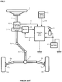
- the column shaft 2 is provided with a torque sensor 10 for detecting a steering torque of the steering wheel 1, and a motor 20 for assisting the steering force of the steering wheel 1 is connected to the column shaft 2 through the reduction gears 3.
- Electric power is supplied to a control unit (ECU) 100 for controlling the electric power steering apparatus from a battery 13, and an ignition key signal is inputted into the control unit 100 through an ignition key 11.
- the control unit 100 calculates a current command value of an assist (steering assist) command based on a steering torque Tr detected by the torque sensor 10 and a vehicle speed Vel detected by a vehicle speed sensor 12, and controls a current supplied to the motor 20 based on a voltage control value E obtained by performing compensation and so on with respect to the current command value.
- CAN controller area network
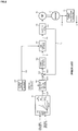
- the control unit 100 mainly comprises a CPU (or an MPU or an MCU), and general functions performed by programs within the CPU are shown in FIG.2 .
- the steering torque Tr detected by the torque sensor 10 and the vehicle speed Vel from the vehicle speed sensor 12 are inputted into a current command value calculating section 101, and a current command value Iref1 is calculated by means of an assist map and so on.
- the calculated current command value Iref1 is inputted into a maximum output limiting section 102 and an output is limited based on an overheat protection condition or the like in the maximum output limiting section 102.
- a current command value Iref2 that a maximum output is limited, is inputted into a subtracting section 103.
- a torque control section is comprised of the current command value calculating section 101 and the maximum output limiting section 102.
- a current control section 104 such as a PI control (proportional and integral control) or the like.
- the motor current Im of the motor 20 is detected by a current detecting circuit 120 within the inverter 106, and the detected motor current Im is inputted into the subtracting section 103 to feed back.
- a brushless DC motor as the motor 20 is used for a vector-control
- a resolver 21 as a rotation sensor is connected to the motor 20, and an angular speed calculating section 22 for calculating an angular speed ⁇ from a motor angle (rotation angle) ⁇ is provided.
- a bridge circuit that bridge-connects semiconductor switching elements (e.g. FETs) and the motor 20 is used in the inverter 106 that controls the motor current Im by means of the voltage control value E and drives the motor 20, and the motor current Im is controlled by performing ON/OFF controls of the semiconductor switching elements in accordance with the duty command values of the PWM-signal determined based on the voltage control value E.
- semiconductor switching elements e.g. FETs
- the PWM control section 105 comprises a duty calculating section 105A that inputs each-phase carrier signal CS and calculates PWM-duty command values D1 ⁇ D6 of three phases (U-phase, V-phase and W-phase) in accordance with a predetermined expression based on the voltage control value E, and a gate driving section 105B that drives each gate of FET1 ⁇ FET6 by the PWM-duty command values D1 ⁇ D6 to turn ON/OFF.
- the inverter 106 comprises a three-phase bridge having upper/lower arms comprised of a U-phase upper-stage FET1 and a U-phase lower-stage FET4, upper/lower arms comprised of a V-phase upper-stage FET2 and a V-phase lower-stage FET5, and upper/lower arms comprised of a W-phase upper-stage FET3 and a W-phase lower-stage FET6, and drives the motor 20 by being turned ON/OFF with the PWM-duty command values D1 ⁇ D6. Further, electric power is supplied to the inverter 106 from the battery 13 through a power-source relay 14.
- a 1-shunt type current detecting circuit is known as the singularity of a current detecting circuit, and for example, the conf igurationof the 1-shunt type current detection circuit 120 is shown in FIG.4 (for example, Japanese Published Unexamined Patent Application No.2009-131064 A ).
- a shunt resistor R1 is connected between the lower-stage arm of the FET bridge and the ground (GND), a fall voltage that is caused by the shunt resistor R1 when a current flowed in the FET bridge is converted into a current value Ima by an operational amplifier (a differential amplification circuit) 121 and resistors R2 ⁇ R4, and further the current value Ima is A/D-convertedat a predetermined timing by anA/D converting section 122 through a filter comprised of a resistor R6 and a capacitor C1, and then a current value Im that is a digital value is outputted.
- a voltage "2.5V" being a reference voltage is connected to a positive input terminal of the operational amplifier 121 through a resistor R5.
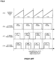
- Patent Document 1 a method that a judgement of the maximum duty, the intermediate duty and the minimum duty is performed and then the judged duties are sequentially arranged with respect to the shifted carrier period, is used. That is, the duty setting values for respective phases are compared, an then the maximum duty, the intermediate duty and the minimum duty are determined, as a reference being a rising phase Y of the carrier signal of the intermediate phase, a rising phase of the carrier signal of the maximum phase is led by a constant amount as well as a rising phase of the carrier signal of the minimum phase is lagged by a constant amount.
- the PWM-signals for the respective phases are generated based on the respective-phase carrier signals of which phases are sifted each other and the respective-phase duty setting values, and the current detection is performed in predetermined sections (periods) Tu and Tw till the respective risings of the PWM-signal of the intermediate phase and the PWM-signal of the minimum phase so as to be possible to detect the respective-phase motor currents by the single current detecting circuit.
- FIG.6 shows the operations thereof
- FIG.6(A) does an appearance that the phase order of the V-phase duty command value is switched from the intermediate phase to the minimum phase at a time point t1
- FIG.6(B) does the V-phase current based on the V-phase duty command value and does a matter that a current variation (distortion) due to a temporary duty variation which is generated by switching the phases occurs after the time point t1.
- FIG.6(C) shows an appearance that the phase order of the W-phase duty command value is switched from the minimum phase to the intermediate phase at the time point t1
- FIG. 6 (D) does the W-phase current based on the W-phase duty command value and does a matter that a current variation (distortion) due to a temporary duty variation which is generated by switching the phases occurs after the time point t1.
- the variations are generated in the V-phase current and the W-phase current and the motor current varies as shown in FIG.6 6(E) .
- the motor angle detection value varies as shown in FIG.6(F) and the current command value to be calculated varies as shown in FIG.6(G) .
- the duty command values of UVW-phases vary as shown in FIGs. 6 (H) ⁇ (J) , and therefore the noises occur and the sound and the vibration are generated.
- the variation of the phase-order due to the PWM phase-shift occurs at a moment of the PWM phase-shift, this variation of the phase-order causes, for example, the variations (distortions) of the V-phase current and the W-phase current and further the current distortion causes the variation of the motor angle.
- the motor angle detection value also varies, the torque control section and the current control section react in sensitive to the variation of the detection value, and the variations of the current command value and the duty command value occur.
- a series of a feedback loop that the V-phase current and the W-phase current more vary is formed, and an undesirable phenomenon occurring the noisy sound, the vibration or the like is caused.
- the occurring of the sound and the vibration gives an uncomfortable feeling to the driver and deteriorates the steering performance.
- Patent Document 3 a control apparatus disclosed in Japanese Published Unexamined Patent Application No.2012-125106 A (Patent Document 3)
- the reducing of the angle detection noise due to the switching noise is performed with a correction 1 relating to the rotation speed and a correction 2 relating to the percentage modulation.
- Patent Document 3 since whole signal-processing is performed by utilizing the present value detected by the resolver, there is a problem that the variation of the resolver output signal itself directly influences to the apparatus.
- Patent Documents 2 and 3 do not disclose only detection method of the motor current but also consider the downsizing, the weight saving and the cost-cutting.
- the present invention has been developed in view of the above-described circumstances, and an object of the present invention is to provide a motor control apparatus that detects a motor current by using a cheap and compact 1-shunt type current detecting circuit, does not occur the variations of the current command value and the duty command values even if the duty variation due to PWM phase-shift occurs at a moment of the PWM phase-shift, and further does not occur an uncomfortable phenomenon such as noisy sound and variation, and to provide an electric power steering apparatus using the same.
- the present invention relates to a motor control apparatus, the above-described object of the present invention is achieved by that: said motor control apparatus that calculates duty command values of respective phases for controlling currents of a motor by means of a control calculation, forms PWM-signals in correspondence to said duty command values of said respective phase, drives said motor by means of an inverter based on said PWM-signals, and which is provided a rotation sensor to detect a motor angle of said motor: wherein a 1-shunt type current detecting circuit is connected to a power source side or a ground side of said inverter; and comprising; a comparing section to compare said duty command values and to determine a size relation of said duty command values; a timing control section to sequentially enable timings of rising or falling with respect to said PWM-signals with a predetermined order based on said size relation; and a motor angle output section to change an order of said rising in correspondence to a predetermined algorithm, estimate a motor angle estimation value based on past values of said rotation sensor at only a timing when said
- said predetermined order is an order of a maximum phase, an intermediate phase, a minimum phase of said duty command values
- said predetermined algorithm is an algorithm that said order of said rising is also changed at a timing when a relation of a maximum phase, an intermediate phase and a minimum phase of said respective phases is changed
- said motor angle output section comprising a phase-change detecting section to detect a change of a relation of said maximum phase, said intermediate phase and said minimum phase, a storing section to store a motor angle of said rotation sensor with a predetermined period, and a motor angle estimating section to estimate said motor angle estimation value from plural past values in said storing section, wherein said motor angle estimating section estimates said motor angle estimation value by means of a linear approximation, or wherein said rotation sensor is a resolver.
- the motor angle is estimated with a linear approximation by using plural past values in the storing section without using of the motor angle (angle signal) from the rotation sensor (e.g. resolver) at a timing of the PWM phase-shift, and the estimated motor estimation value is used for the control. Therefore, it is possible to minimize or suppress a variation of the motor angle detection value which is one of the feedbacks causing the uncomfortable phenomenon such as the sound and the vibration.
- the current command value becomes a smooth command value wave form that the variation of the motor angle detection value does not propagate.
- the duty command values are also able to obtain the smooth duty command value wave form that the above variation does not influence.
- the duty command values become the smooth wave form without an influence of the variation of the motor angle detection value, it is possible to reduce or suppress the occurrence of the uncomfortable phenomenon for the motor control apparatus and the electric power steering apparatus.
- a single current detecting circuit (1-shunt type current detecting circuit) is provided between an inverter and a power source or between the inverter and the ground (GND).
- the maximum duty, an intermediate duty and the minimum duty are determined by comparing the sizes of the duty command values of the respective phases, as a reference being a rising phase of the carrier signal of the intermediate phase, a rising phase of the carrier signal of the maximum phase is led by a constant amount as well as a rising phase of the carrier signal of the minimum phase is lagged by a constant amount, whereby the PWM-signals for the respective phases are generated based on the respective-phase carrier signals of which phases are sifted each other and the respective-phase duty setting values, and the current detection is performed in predetermined sections (periods) till the respective risings of the PWM-signal of the intermediate phase and the PWM-
- the present invention detects the switching of the phase-order of duty patterns, does not use a motor angle (angle signal) detected by a resolver or the like only at a timing of a detected phase-order switching and uses a motor angle estimation signal which is estimated from plural stored values (motor angles) just before the timing. Thereby, it is possible to prevent or suppress the variation of the duty command vales due to the variation of the motor angle detection at the timing of the phase-order switching without pass through a special filter.
- the motor angle detected by the resolver or the like is, as it is, used except for the timing of the phase-order switching of the duty patterns.
- FIG. 7 shows one example of the embodiment of the present invention in correspondence to FIG.2 .
- a duty setting section 130 to set duty command values DS corresponding to the duties of PWM-signals of respective phases based on the voltage control value E from the current control section 104 and the carrier signal CS;
- a comparing section 131 to compare the duty command values of respective phases set in the duty setting section 130, determine the maximum phase, the intermediate phase and the minimum phase of the duty command values DS and outputs a size relation signal SR;
- a timing control section 132 to raise timings of rising or falling of the PWM-signals of 3-phases at a predetermined order, for example, at an order of "the maximum phase” ⁇ "the intermediate phase” ⁇ "the minimum phase” of the duty command values based on the size relation signal SR from the comparing section 131 and the carrier signal SR and to output the PWM-signals for driving the motor 20 via the inverter 106.
- phase-change detecting section 142 to detect an fact that the order of the rising of the 3-phase PWM-signals outputted from the timing control section 132 is changed and to output a phase-change signal PC at the time when the change is occurred; a storing section 141 to store the motor angle ⁇ from the resolver 21 at a predetermined period; and a motor angle estimating section 140 to read out a stored angle data ⁇ m of the past plural times from the storing section 141 only at a time when the phase-change signal PC is outputted from the phase-change detecting section 142, estimate the motor angle by means of the linear approximation and output a motor angle estimation value ⁇ e.
- the motor angle ⁇ of the resolver 21 is, as it is, outputted as the motor angle estimation signal ⁇ e. Namely, when the phase-change signal PC is not outputted, the motor angle estimation signal ⁇ e is equal to the motor angle ⁇ . Further, the current command value Iref2 calculated in the torque control section 110 is inputted into the subtracting section 103 , and the current command value Iref3 which is a deviationbetween the current command value Iref2 and the motor current Im detected by the 1-shunt type current detecting circuit 120, is inputted into the current control section 104.
- the storing section 141 actually stores, at a predetermined sampling period, the digital values A/D-converted by an A/D converter or the like as the motor angle ⁇ . Further, a motor angle output section is comprised of the motor angle estimating section 140, the storing section 141 and the phase-change detecting section 142.
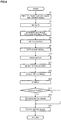
- FIG. 8 shows only a part relating to the present invention.
- the duty setting section 130 inputs the voltage control value E calculated in the current control section 104 and the carrier signal CS generated in the carrier signal generating section 107 (Step S1), and sets the duty command values DS corresponding to the duty of PWM-signals of respective phases (Step S2).
- the duty command values DS set in the duty setting section 130 are inputted into the comparing section 131, the comparing section 131 compares the duty command values DS of the respective phases, determine the maximum phase, the intermediate phase and the minimum phase of the duty command values DS and outputs the size relation signal SR (Step S3).
- the timing control section 132 inputs the size relation signal SR from the comparing section 131, and raises the timings of rising (or falling) of the PWM-signals of 3-phases at the predetermined order (Step S4).
- the predetermined order is, for example, an order of "the maximum phase” ⁇ "the intermediate phase” ⁇ "the minimum phase”, or an order of "the minimum phase” ⁇ “the intermediate phase” ⁇ “the maximum phase” or the like.
- the PWM-signals controlled the timings in the timing control section 132 are outputted (Step S5), and the motor 20 is driven by using the PWM-signals PS via the inverter 106 (Step S10).
- the respective phase motor currents of the motor 20 are detected by the 1-shunt type detecting circuit 120 as stated above (Step S11), the detected motor currents Im is fed back to the subtracting section 103. Further, the motor angle ⁇ is detected by the resolver 21 (Step S21), and the detected motor angle ⁇ is stored in the storing section 141 at a predetermined sampling period (Step S13).
- the phase-change detecting section 142 detects whether there is a phase-change by changing the order of the rising based on the PWM-signals or not (Step S14), when the phase-change is detected, the phase-change detecting section 142 outputs the phase-change signal PC.
- the phase change signal PC is inputted into the storing section 141 and the motor angle estimating section 140, the motor angle estimating section 140 reads out plural past motor angles ⁇ m just before input of the phase-change signal PC and estimates the motor angle ⁇ e by means of the linear approximation based on the plural motor angles ⁇ m (Step S20).
- the estimated motor estimation value ⁇ e is outputted from the motor angle estimating section 140 (Step S30).
- the flow chart of FIG.9 shows the details of the motor angle estimation at the Step S20, when the phase-change signal PC is inputted from the phase-change detecting section 142 (Step S21), the motor angle estimating section 140 reads out plural past stored values (motor angles ⁇ m) from the storing section 141 (Step S22). The motor angle estimating section 140 estimates the motor angle with the known linear approximate calculation by using the plural past stored values (Step S23), and outputs the estimated motor angle estimation value ⁇ e (Step S24).
- FIG.10 shows effects of the present invention with reference to FIG.6 .
- the motor angle estimating section 140 estimates the motor angle as shown in FIG.10 (F) by means of the linear approximation, a logarithmic approximation and so on from the past values ⁇ m of the motor angle ⁇ based on the phase-change signal PC detected by the phase-change detecting section 142. Then, the estimated motor angle estimation value ⁇ e is used for the control calculation. Consequently, as shown in FIGs. 10 (G) ⁇ (J) , variations in the current command value and the duty command values do not occur, and it is possible to output smooth current command value and the duty command values.
Landscapes
- Engineering & Computer Science (AREA)
- Power Engineering (AREA)
- Chemical & Material Sciences (AREA)
- Combustion & Propulsion (AREA)
- Transportation (AREA)
- Mechanical Engineering (AREA)
- Control Of Motors That Do Not Use Commutators (AREA)
- Power Steering Mechanism (AREA)
- Steering Control In Accordance With Driving Conditions (AREA)
Applications Claiming Priority (1)
| Application Number | Priority Date | Filing Date | Title |
|---|---|---|---|
| PCT/JP2014/083687 WO2016098244A1 (fr) | 2014-12-19 | 2014-12-19 | Dispositif de commande de moteur et dispositif de direction assistée électrique l'utilisant |
Publications (3)
| Publication Number | Publication Date |
|---|---|
| EP3197041A1 true EP3197041A1 (fr) | 2017-07-26 |
| EP3197041A4 EP3197041A4 (fr) | 2018-06-13 |
| EP3197041B1 EP3197041B1 (fr) | 2019-12-04 |
Family
ID=56126162
Family Applications (1)
| Application Number | Title | Priority Date | Filing Date |
|---|---|---|---|
| EP14908454.3A Not-in-force EP3197041B1 (fr) | 2014-12-19 | 2014-12-19 | Dispositif de commande de moteur et dispositif de direction assistée électrique l'utilisant |
Country Status (5)
| Country | Link |
|---|---|
| US (1) | US9882519B2 (fr) |
| EP (1) | EP3197041B1 (fr) |
| CN (1) | CN107155391B (fr) |
| BR (1) | BR112017013124A2 (fr) |
| WO (1) | WO2016098244A1 (fr) |
Cited By (1)
| Publication number | Priority date | Publication date | Assignee | Title |
|---|---|---|---|---|
| CN110224641A (zh) * | 2018-03-01 | 2019-09-10 | 株式会社东芝 | 电机控制用集成电路 |
Families Citing this family (5)
| Publication number | Priority date | Publication date | Assignee | Title |
|---|---|---|---|---|
| WO2016163343A1 (fr) * | 2015-04-10 | 2016-10-13 | 日本精工株式会社 | Dispositif de commande de moteur et dispositif de direction assistée électrique le comportant |
| DE102015211260A1 (de) * | 2015-06-18 | 2016-12-22 | Robert Bosch Gmbh | Verfahren und Vorrichtung zur Bestimmung eines Sensorsignals |
| EP3588767B1 (fr) | 2017-10-26 | 2021-11-24 | NSK Ltd. | Dispositif de commande de moteur et procédé de commande de moteur |
| WO2019186757A1 (fr) * | 2018-03-28 | 2019-10-03 | 新電元工業株式会社 | Dispositif d'entraînement, procédé d'entraînement, programme d'entraînement et véhicule électrique |
| WO2021144234A1 (fr) * | 2020-01-13 | 2021-07-22 | Convertertec Deutschland Gmbh | Procédé de protection contre les surintensités à séparation de phase d'un circuit en pont triphasé |
Family Cites Families (11)
| Publication number | Priority date | Publication date | Assignee | Title |
|---|---|---|---|---|
| JPH08237986A (ja) * | 1995-02-27 | 1996-09-13 | Hitachi Ltd | 回転位置検出装置及び検出方法 |
| JP2006033903A (ja) * | 2004-07-12 | 2006-02-02 | Matsushita Electric Ind Co Ltd | モータ制御装置 |
| JP5398356B2 (ja) * | 2009-05-28 | 2014-01-29 | オムロンオートモーティブエレクトロニクス株式会社 | 電動機制御装置 |
| JP5178799B2 (ja) * | 2010-09-27 | 2013-04-10 | 株式会社東芝 | モータ制御装置 |
| JP5522476B2 (ja) | 2010-12-10 | 2014-06-18 | アイシン・エィ・ダブリュ株式会社 | 制御装置 |
| JP5402948B2 (ja) | 2011-01-05 | 2014-01-29 | 日本精工株式会社 | モータ制御装置及びそれを用いた電動パワーステアリング装置 |
| JP6145274B2 (ja) * | 2013-01-18 | 2017-06-07 | 日立オートモティブシステムズ株式会社 | ブラシレスモータの駆動装置 |
| JP6067402B2 (ja) * | 2013-02-13 | 2017-01-25 | 株式会社東芝 | モータ制御装置 |
| JP5968805B2 (ja) * | 2013-02-28 | 2016-08-10 | 日立オートモティブシステムズ株式会社 | モータ装置およびモータ駆動装置 |
| JP5908424B2 (ja) * | 2013-03-25 | 2016-04-26 | 日立オートモティブシステムズステアリング株式会社 | モータ制御装置およびパワーステアリング装置 |
| JP2015050909A (ja) * | 2013-09-04 | 2015-03-16 | オムロンオートモーティブエレクトロニクス株式会社 | モータ制御装置 |
-
2014
- 2014-12-19 EP EP14908454.3A patent/EP3197041B1/fr not_active Not-in-force
- 2014-12-19 BR BR112017013124A patent/BR112017013124A2/pt not_active Application Discontinuation
- 2014-12-19 US US14/648,086 patent/US9882519B2/en active Active
- 2014-12-19 CN CN201480084178.7A patent/CN107155391B/zh not_active Expired - Fee Related
- 2014-12-19 WO PCT/JP2014/083687 patent/WO2016098244A1/fr not_active Ceased
Cited By (2)
| Publication number | Priority date | Publication date | Assignee | Title |
|---|---|---|---|---|
| CN110224641A (zh) * | 2018-03-01 | 2019-09-10 | 株式会社东芝 | 电机控制用集成电路 |
| CN110224641B (zh) * | 2018-03-01 | 2023-04-28 | 株式会社东芝 | 电机控制用集成电路 |
Also Published As
| Publication number | Publication date |
|---|---|
| US20170279394A1 (en) | 2017-09-28 |
| CN107155391A (zh) | 2017-09-12 |
| BR112017013124A2 (pt) | 2017-12-26 |
| EP3197041A4 (fr) | 2018-06-13 |
| US9882519B2 (en) | 2018-01-30 |
| EP3197041B1 (fr) | 2019-12-04 |
| CN107155391B (zh) | 2019-11-12 |
| WO2016098244A1 (fr) | 2016-06-23 |
Similar Documents
| Publication | Publication Date | Title |
|---|---|---|
| US9667179B2 (en) | Multi-phase motor control apparatus and electric power steering apparatus using the same | |
| EP3197041B1 (fr) | Dispositif de commande de moteur et dispositif de direction assistée électrique l'utilisant | |
| JP4322254B2 (ja) | 電動パワーステアリング装置の制御装置 | |
| US9197145B2 (en) | Motor control apparatus and power steering apparatus | |
| EP2621080B1 (fr) | Dispositif de commande de moteur et dispositif de direction à énergie électrique | |
| JP5196211B2 (ja) | 車両用操舵装置 | |
| US9184690B2 (en) | Electrically driven power steering system and control apparatus for the same | |
| EP3020615B1 (fr) | Dispositif de direction assistée électrique | |
| EP3148071B1 (fr) | Dispositif de direction assistée électrique | |
| EP1863163B1 (fr) | Contrôleur de moteur | |
| US20200395882A1 (en) | Electric power steering apparatus | |
| JP5929521B2 (ja) | モータ制御装置及びそれを用いた電動パワーステアリング装置 | |
| JP6136803B2 (ja) | モータ制御装置及びそれを用いた電動パワーステアリング装置 | |
| JP4794603B2 (ja) | ブラシレスモータ制御装置 | |
| KR20150055354A (ko) | 전동식 파워 스티어링의 모터 위치의 보상 제어장치 및 그 방법 | |
| JP4556464B2 (ja) | 電動パワーステアリング装置の制御装置 | |
| KR20150062304A (ko) | 전자식 조향 장치 및 이를 이용한 모터 전류 제어 방법 |
Legal Events
| Date | Code | Title | Description |
|---|---|---|---|
| STAA | Information on the status of an ep patent application or granted ep patent |
Free format text: STATUS: THE INTERNATIONAL PUBLICATION HAS BEEN MADE |
|
| PUAI | Public reference made under article 153(3) epc to a published international application that has entered the european phase |
Free format text: ORIGINAL CODE: 0009012 |
|
| STAA | Information on the status of an ep patent application or granted ep patent |
Free format text: STATUS: REQUEST FOR EXAMINATION WAS MADE |
|
| 17P | Request for examination filed |
Effective date: 20170419 |
|
| AK | Designated contracting states |
Kind code of ref document: A1 Designated state(s): AL AT BE BG CH CY CZ DE DK EE ES FI FR GB GR HR HU IE IS IT LI LT LU LV MC MK MT NL NO PL PT RO RS SE SI SK SM TR |
|
| AX | Request for extension of the european patent |
Extension state: BA ME |
|
| DAX | Request for extension of the european patent (deleted) | ||
| A4 | Supplementary search report drawn up and despatched |
Effective date: 20180516 |
|
| RIC1 | Information provided on ipc code assigned before grant |
Ipc: H02P 6/08 20160101AFI20180509BHEP |
|
| STAA | Information on the status of an ep patent application or granted ep patent |
Free format text: STATUS: EXAMINATION IS IN PROGRESS |
|
| 17Q | First examination report despatched |
Effective date: 20190115 |
|
| GRAP | Despatch of communication of intention to grant a patent |
Free format text: ORIGINAL CODE: EPIDOSNIGR1 |
|
| STAA | Information on the status of an ep patent application or granted ep patent |
Free format text: STATUS: GRANT OF PATENT IS INTENDED |
|
| INTG | Intention to grant announced |
Effective date: 20190627 |
|
| GRAS | Grant fee paid |
Free format text: ORIGINAL CODE: EPIDOSNIGR3 |
|
| GRAA | (expected) grant |
Free format text: ORIGINAL CODE: 0009210 |
|
| STAA | Information on the status of an ep patent application or granted ep patent |
Free format text: STATUS: THE PATENT HAS BEEN GRANTED |
|
| AK | Designated contracting states |
Kind code of ref document: B1 Designated state(s): AL AT BE BG CH CY CZ DE DK EE ES FI FR GB GR HR HU IE IS IT LI LT LU LV MC MK MT NL NO PL PT RO RS SE SI SK SM TR |
|
| REG | Reference to a national code |
Ref country code: GB Ref legal event code: FG4D |
|
| REG | Reference to a national code |
Ref country code: CH Ref legal event code: EP |
|
| REG | Reference to a national code |
Ref country code: AT Ref legal event code: REF Ref document number: 1210686 Country of ref document: AT Kind code of ref document: T Effective date: 20191215 |
|
| REG | Reference to a national code |
Ref country code: DE Ref legal event code: R096 Ref document number: 602014058095 Country of ref document: DE |
|
| REG | Reference to a national code |
Ref country code: IE Ref legal event code: FG4D |
|
| REG | Reference to a national code |
Ref country code: NL Ref legal event code: MP Effective date: 20191204 |
|
| REG | Reference to a national code |
Ref country code: LT Ref legal event code: MG4D |
|
| PG25 | Lapsed in a contracting state [announced via postgrant information from national office to epo] |
Ref country code: SE Free format text: LAPSE BECAUSE OF FAILURE TO SUBMIT A TRANSLATION OF THE DESCRIPTION OR TO PAY THE FEE WITHIN THE PRESCRIBED TIME-LIMIT Effective date: 20191204 Ref country code: LV Free format text: LAPSE BECAUSE OF FAILURE TO SUBMIT A TRANSLATION OF THE DESCRIPTION OR TO PAY THE FEE WITHIN THE PRESCRIBED TIME-LIMIT Effective date: 20191204 Ref country code: LT Free format text: LAPSE BECAUSE OF FAILURE TO SUBMIT A TRANSLATION OF THE DESCRIPTION OR TO PAY THE FEE WITHIN THE PRESCRIBED TIME-LIMIT Effective date: 20191204 Ref country code: FI Free format text: LAPSE BECAUSE OF FAILURE TO SUBMIT A TRANSLATION OF THE DESCRIPTION OR TO PAY THE FEE WITHIN THE PRESCRIBED TIME-LIMIT Effective date: 20191204 Ref country code: BG Free format text: LAPSE BECAUSE OF FAILURE TO SUBMIT A TRANSLATION OF THE DESCRIPTION OR TO PAY THE FEE WITHIN THE PRESCRIBED TIME-LIMIT Effective date: 20200304 Ref country code: NO Free format text: LAPSE BECAUSE OF FAILURE TO SUBMIT A TRANSLATION OF THE DESCRIPTION OR TO PAY THE FEE WITHIN THE PRESCRIBED TIME-LIMIT Effective date: 20200304 Ref country code: GR Free format text: LAPSE BECAUSE OF FAILURE TO SUBMIT A TRANSLATION OF THE DESCRIPTION OR TO PAY THE FEE WITHIN THE PRESCRIBED TIME-LIMIT Effective date: 20200305 |
|
| PG25 | Lapsed in a contracting state [announced via postgrant information from national office to epo] |
Ref country code: RS Free format text: LAPSE BECAUSE OF FAILURE TO SUBMIT A TRANSLATION OF THE DESCRIPTION OR TO PAY THE FEE WITHIN THE PRESCRIBED TIME-LIMIT Effective date: 20191204 Ref country code: HR Free format text: LAPSE BECAUSE OF FAILURE TO SUBMIT A TRANSLATION OF THE DESCRIPTION OR TO PAY THE FEE WITHIN THE PRESCRIBED TIME-LIMIT Effective date: 20191204 |
|
| PG25 | Lapsed in a contracting state [announced via postgrant information from national office to epo] |
Ref country code: AL Free format text: LAPSE BECAUSE OF FAILURE TO SUBMIT A TRANSLATION OF THE DESCRIPTION OR TO PAY THE FEE WITHIN THE PRESCRIBED TIME-LIMIT Effective date: 20191204 |
|
| PG25 | Lapsed in a contracting state [announced via postgrant information from national office to epo] |
Ref country code: CZ Free format text: LAPSE BECAUSE OF FAILURE TO SUBMIT A TRANSLATION OF THE DESCRIPTION OR TO PAY THE FEE WITHIN THE PRESCRIBED TIME-LIMIT Effective date: 20191204 Ref country code: RO Free format text: LAPSE BECAUSE OF FAILURE TO SUBMIT A TRANSLATION OF THE DESCRIPTION OR TO PAY THE FEE WITHIN THE PRESCRIBED TIME-LIMIT Effective date: 20191204 Ref country code: ES Free format text: LAPSE BECAUSE OF FAILURE TO SUBMIT A TRANSLATION OF THE DESCRIPTION OR TO PAY THE FEE WITHIN THE PRESCRIBED TIME-LIMIT Effective date: 20191204 Ref country code: NL Free format text: LAPSE BECAUSE OF FAILURE TO SUBMIT A TRANSLATION OF THE DESCRIPTION OR TO PAY THE FEE WITHIN THE PRESCRIBED TIME-LIMIT Effective date: 20191204 Ref country code: EE Free format text: LAPSE BECAUSE OF FAILURE TO SUBMIT A TRANSLATION OF THE DESCRIPTION OR TO PAY THE FEE WITHIN THE PRESCRIBED TIME-LIMIT Effective date: 20191204 Ref country code: PT Free format text: LAPSE BECAUSE OF FAILURE TO SUBMIT A TRANSLATION OF THE DESCRIPTION OR TO PAY THE FEE WITHIN THE PRESCRIBED TIME-LIMIT Effective date: 20200429 |
|
| REG | Reference to a national code |
Ref country code: CH Ref legal event code: PL |
|
| REG | Reference to a national code |
Ref country code: BE Ref legal event code: MM Effective date: 20191231 |
|
| PG25 | Lapsed in a contracting state [announced via postgrant information from national office to epo] |
Ref country code: SK Free format text: LAPSE BECAUSE OF FAILURE TO SUBMIT A TRANSLATION OF THE DESCRIPTION OR TO PAY THE FEE WITHIN THE PRESCRIBED TIME-LIMIT Effective date: 20191204 Ref country code: IS Free format text: LAPSE BECAUSE OF FAILURE TO SUBMIT A TRANSLATION OF THE DESCRIPTION OR TO PAY THE FEE WITHIN THE PRESCRIBED TIME-LIMIT Effective date: 20200404 Ref country code: SM Free format text: LAPSE BECAUSE OF FAILURE TO SUBMIT A TRANSLATION OF THE DESCRIPTION OR TO PAY THE FEE WITHIN THE PRESCRIBED TIME-LIMIT Effective date: 20191204 |
|
| REG | Reference to a national code |
Ref country code: DE Ref legal event code: R097 Ref document number: 602014058095 Country of ref document: DE |
|
| REG | Reference to a national code |
Ref country code: AT Ref legal event code: MK05 Ref document number: 1210686 Country of ref document: AT Kind code of ref document: T Effective date: 20191204 |
|
| PG25 | Lapsed in a contracting state [announced via postgrant information from national office to epo] |
Ref country code: MC Free format text: LAPSE BECAUSE OF FAILURE TO SUBMIT A TRANSLATION OF THE DESCRIPTION OR TO PAY THE FEE WITHIN THE PRESCRIBED TIME-LIMIT Effective date: 20191204 |
|
| PLBE | No opposition filed within time limit |
Free format text: ORIGINAL CODE: 0009261 |
|
| STAA | Information on the status of an ep patent application or granted ep patent |
Free format text: STATUS: NO OPPOSITION FILED WITHIN TIME LIMIT |
|
| PG25 | Lapsed in a contracting state [announced via postgrant information from national office to epo] |
Ref country code: LU Free format text: LAPSE BECAUSE OF NON-PAYMENT OF DUE FEES Effective date: 20191219 Ref country code: IE Free format text: LAPSE BECAUSE OF NON-PAYMENT OF DUE FEES Effective date: 20191219 Ref country code: DK Free format text: LAPSE BECAUSE OF FAILURE TO SUBMIT A TRANSLATION OF THE DESCRIPTION OR TO PAY THE FEE WITHIN THE PRESCRIBED TIME-LIMIT Effective date: 20191204 Ref country code: FR Free format text: LAPSE BECAUSE OF NON-PAYMENT OF DUE FEES Effective date: 20200204 |
|
| 26N | No opposition filed |
Effective date: 20200907 |
|
| PG25 | Lapsed in a contracting state [announced via postgrant information from national office to epo] |
Ref country code: BE Free format text: LAPSE BECAUSE OF NON-PAYMENT OF DUE FEES Effective date: 20191231 Ref country code: AT Free format text: LAPSE BECAUSE OF FAILURE TO SUBMIT A TRANSLATION OF THE DESCRIPTION OR TO PAY THE FEE WITHIN THE PRESCRIBED TIME-LIMIT Effective date: 20191204 Ref country code: SI Free format text: LAPSE BECAUSE OF FAILURE TO SUBMIT A TRANSLATION OF THE DESCRIPTION OR TO PAY THE FEE WITHIN THE PRESCRIBED TIME-LIMIT Effective date: 20191204 Ref country code: PL Free format text: LAPSE BECAUSE OF FAILURE TO SUBMIT A TRANSLATION OF THE DESCRIPTION OR TO PAY THE FEE WITHIN THE PRESCRIBED TIME-LIMIT Effective date: 20191204 Ref country code: CH Free format text: LAPSE BECAUSE OF NON-PAYMENT OF DUE FEES Effective date: 20191231 Ref country code: LI Free format text: LAPSE BECAUSE OF NON-PAYMENT OF DUE FEES Effective date: 20191231 |
|
| PG25 | Lapsed in a contracting state [announced via postgrant information from national office to epo] |
Ref country code: IT Free format text: LAPSE BECAUSE OF FAILURE TO SUBMIT A TRANSLATION OF THE DESCRIPTION OR TO PAY THE FEE WITHIN THE PRESCRIBED TIME-LIMIT Effective date: 20191204 |
|
| GBPC | Gb: european patent ceased through non-payment of renewal fee |
Effective date: 20200304 |
|
| PG25 | Lapsed in a contracting state [announced via postgrant information from national office to epo] |
Ref country code: GB Free format text: LAPSE BECAUSE OF NON-PAYMENT OF DUE FEES Effective date: 20200304 |
|
| PG25 | Lapsed in a contracting state [announced via postgrant information from national office to epo] |
Ref country code: CY Free format text: LAPSE BECAUSE OF FAILURE TO SUBMIT A TRANSLATION OF THE DESCRIPTION OR TO PAY THE FEE WITHIN THE PRESCRIBED TIME-LIMIT Effective date: 20191204 |
|
| PG25 | Lapsed in a contracting state [announced via postgrant information from national office to epo] |
Ref country code: MT Free format text: LAPSE BECAUSE OF FAILURE TO SUBMIT A TRANSLATION OF THE DESCRIPTION OR TO PAY THE FEE WITHIN THE PRESCRIBED TIME-LIMIT Effective date: 20191204 Ref country code: HU Free format text: LAPSE BECAUSE OF FAILURE TO SUBMIT A TRANSLATION OF THE DESCRIPTION OR TO PAY THE FEE WITHIN THE PRESCRIBED TIME-LIMIT; INVALID AB INITIO Effective date: 20141219 |
|
| PG25 | Lapsed in a contracting state [announced via postgrant information from national office to epo] |
Ref country code: TR Free format text: LAPSE BECAUSE OF FAILURE TO SUBMIT A TRANSLATION OF THE DESCRIPTION OR TO PAY THE FEE WITHIN THE PRESCRIBED TIME-LIMIT Effective date: 20191204 |
|
| PG25 | Lapsed in a contracting state [announced via postgrant information from national office to epo] |
Ref country code: MK Free format text: LAPSE BECAUSE OF FAILURE TO SUBMIT A TRANSLATION OF THE DESCRIPTION OR TO PAY THE FEE WITHIN THE PRESCRIBED TIME-LIMIT Effective date: 20191204 |
|
| PGFP | Annual fee paid to national office [announced via postgrant information from national office to epo] |
Ref country code: DE Payment date: 20221102 Year of fee payment: 9 |
|
| REG | Reference to a national code |
Ref country code: DE Ref legal event code: R119 Ref document number: 602014058095 Country of ref document: DE |
|
| PG25 | Lapsed in a contracting state [announced via postgrant information from national office to epo] |
Ref country code: DE Free format text: LAPSE BECAUSE OF NON-PAYMENT OF DUE FEES Effective date: 20240702 |
|
| PG25 | Lapsed in a contracting state [announced via postgrant information from national office to epo] |
Ref country code: DE Free format text: LAPSE BECAUSE OF NON-PAYMENT OF DUE FEES Effective date: 20240702 |