EP3199288A2 - Dispositif d'alimentation en éléments d'un appareil de placement et de soudage, appareil de placement et de soudage et procédé d'assemblage sous la forme d'un processus de placement et de soudage mécano-thermique - Google Patents
Dispositif d'alimentation en éléments d'un appareil de placement et de soudage, appareil de placement et de soudage et procédé d'assemblage sous la forme d'un processus de placement et de soudage mécano-thermique Download PDFInfo
- Publication number
- EP3199288A2 EP3199288A2 EP17152927.4A EP17152927A EP3199288A2 EP 3199288 A2 EP3199288 A2 EP 3199288A2 EP 17152927 A EP17152927 A EP 17152927A EP 3199288 A2 EP3199288 A2 EP 3199288A2
- Authority
- EP
- European Patent Office
- Prior art keywords
- welding
- electrode
- punch
- setting
- joining
- Prior art date
- Legal status (The legal status is an assumption and is not a legal conclusion. Google has not performed a legal analysis and makes no representation as to the accuracy of the status listed.)
- Granted
Links
Images





Classifications
-
- B—PERFORMING OPERATIONS; TRANSPORTING
- B23—MACHINE TOOLS; METAL-WORKING NOT OTHERWISE PROVIDED FOR
- B23K—SOLDERING OR UNSOLDERING; WELDING; CLADDING OR PLATING BY SOLDERING OR WELDING; CUTTING BY APPLYING HEAT LOCALLY, e.g. FLAME CUTTING; WORKING BY LASER BEAM
- B23K11/00—Resistance welding; Severing by resistance heating
- B23K11/10—Spot welding; Stitch welding
-
- B—PERFORMING OPERATIONS; TRANSPORTING
- B23—MACHINE TOOLS; METAL-WORKING NOT OTHERWISE PROVIDED FOR
- B23K—SOLDERING OR UNSOLDERING; WELDING; CLADDING OR PLATING BY SOLDERING OR WELDING; CUTTING BY APPLYING HEAT LOCALLY, e.g. FLAME CUTTING; WORKING BY LASER BEAM
- B23K11/00—Resistance welding; Severing by resistance heating
- B23K11/36—Auxiliary equipment
-
- B—PERFORMING OPERATIONS; TRANSPORTING
- B23—MACHINE TOOLS; METAL-WORKING NOT OTHERWISE PROVIDED FOR
- B23K—SOLDERING OR UNSOLDERING; WELDING; CLADDING OR PLATING BY SOLDERING OR WELDING; CUTTING BY APPLYING HEAT LOCALLY, e.g. FLAME CUTTING; WORKING BY LASER BEAM
- B23K11/00—Resistance welding; Severing by resistance heating
- B23K11/30—Features relating to electrodes
-
- B—PERFORMING OPERATIONS; TRANSPORTING
- B21—MECHANICAL METAL-WORKING WITHOUT ESSENTIALLY REMOVING MATERIAL; PUNCHING METAL
- B21J—FORGING; HAMMERING; PRESSING METAL; RIVETING; FORGE FURNACES
- B21J15/00—Riveting
- B21J15/10—Riveting machines
- B21J15/30—Particular elements, e.g. supports; Suspension equipment specially adapted for portable riveters
- B21J15/32—Devices for inserting or holding rivets in position with or without feeding arrangements
-
- B—PERFORMING OPERATIONS; TRANSPORTING
- B23—MACHINE TOOLS; METAL-WORKING NOT OTHERWISE PROVIDED FOR
- B23K—SOLDERING OR UNSOLDERING; WELDING; CLADDING OR PLATING BY SOLDERING OR WELDING; CUTTING BY APPLYING HEAT LOCALLY, e.g. FLAME CUTTING; WORKING BY LASER BEAM
- B23K11/00—Resistance welding; Severing by resistance heating
- B23K11/002—Resistance welding; Severing by resistance heating specially adapted for particular articles or work
- B23K11/004—Welding of a small piece to a large or broad piece
- B23K11/0046—Welding of a small piece to a large or broad piece the extremity of a small piece being welded to a base, e.g. cooling studs or fins to tubes or plates
- B23K11/0053—Stud welding, i.e. resistive
-
- B—PERFORMING OPERATIONS; TRANSPORTING
- B23—MACHINE TOOLS; METAL-WORKING NOT OTHERWISE PROVIDED FOR
- B23K—SOLDERING OR UNSOLDERING; WELDING; CLADDING OR PLATING BY SOLDERING OR WELDING; CUTTING BY APPLYING HEAT LOCALLY, e.g. FLAME CUTTING; WORKING BY LASER BEAM
- B23K11/00—Resistance welding; Severing by resistance heating
- B23K11/002—Resistance welding; Severing by resistance heating specially adapted for particular articles or work
- B23K11/004—Welding of a small piece to a large or broad piece
- B23K11/0066—Riveting
-
- B—PERFORMING OPERATIONS; TRANSPORTING
- B23—MACHINE TOOLS; METAL-WORKING NOT OTHERWISE PROVIDED FOR
- B23K—SOLDERING OR UNSOLDERING; WELDING; CLADDING OR PLATING BY SOLDERING OR WELDING; CUTTING BY APPLYING HEAT LOCALLY, e.g. FLAME CUTTING; WORKING BY LASER BEAM
- B23K11/00—Resistance welding; Severing by resistance heating
- B23K11/02—Pressure butt welding
-
- B—PERFORMING OPERATIONS; TRANSPORTING
- B23—MACHINE TOOLS; METAL-WORKING NOT OTHERWISE PROVIDED FOR
- B23K—SOLDERING OR UNSOLDERING; WELDING; CLADDING OR PLATING BY SOLDERING OR WELDING; CUTTING BY APPLYING HEAT LOCALLY, e.g. FLAME CUTTING; WORKING BY LASER BEAM
- B23K11/00—Resistance welding; Severing by resistance heating
- B23K11/10—Spot welding; Stitch welding
- B23K11/11—Spot welding
- B23K11/115—Spot welding by means of two electrodes placed opposite one another on both sides of the welded parts
-
- B—PERFORMING OPERATIONS; TRANSPORTING
- B23—MACHINE TOOLS; METAL-WORKING NOT OTHERWISE PROVIDED FOR
- B23P—METAL-WORKING NOT OTHERWISE PROVIDED FOR; COMBINED OPERATIONS; UNIVERSAL MACHINE TOOLS
- B23P19/00—Machines for simply fitting together or separating metal parts or objects, or metal and non-metal parts, whether or not involving some deformation; Tools or devices therefor so far as not provided for in other classes
- B23P19/001—Article feeders for assembling machines
- B23P19/006—Holding or positioning the article in front of the applying tool
Definitions
- the present invention relates to an element feeding device of a setting and welding device for a bolt-like Sch pasgeteil head and shaft, in which of an electrode punch and an electrode pad for producing a setting-welding connection, a relative joining movement is feasible. Further, the present invention relates to such a setting-welding apparatus and a joining method in the form of a mechanical-thermal setting-welding process using the above-mentioned bolt-like Sch pastells and setting-welding device.
- connection methods include purely mechanical connection methods, such as, for example, punch riveting or bolt setting.
- the joining element is, for example, fed via a profile hose or another compressed air driven element feed arrangement the joining channel of the setting device.
- the punch of the setting device moves as part of a joining movement on a straight line of movement to, for example, a die to make a connection.
- a similar purely mechanical joining method is realized by a nailing device, which is automatically fed a plurality of nails. This is done according to US 5,492,262 a nail strip wound up in a magazine is unwound within a feeding device to transfer individual nails to the joining device. Since these nails are initially connected to each other via the nail strips, just the separation of the nails is complicated and not readily transferable to other joining methods.
- the feed device for the friction welding elements provides a jaw assembly which forms the end forms a feed channel for Reibsch domine.
- the end position of the feed channel is arranged directly below the rotary punch of the friction welding device.
- An axially movable adjusting element with different thickness ranges with respect to the length of the adjusting element is arranged between the two clamping jaws such that an axial offset of the adjusting element causes a differently strong opening of the clamping jaws.
- a thickness range of the actuating element and thus a certain distance of the jaws of the supply of Reibsch resumeelements is assigned, while a larger thickness range of the actuating element and thus a larger opening of the clamping jaws is provided for that the rotary punch takes over there positioned joining element in its passage through the two jaws and a joining position feeds. Due to the combination of the laterally movable clamping jaws and the axially displaceable adjusting element in the immediate vicinity of the rotary punch, this is a complex and space-intensive design, which is just adapted to the supply of purely mechanical torque loads to a joining element.
- the welding auxiliary joining part is arranged within the welding electrode by means of a holding device. This ensures that even before the start of the welding process, the lever arm and thus the feeding device can be removed from the electrodes of the welding device. Since the welding auxiliary joining part is merely clamped in the electrode, this results in inaccuracies in the positioning of the welding auxiliary joining part at the joint. Furthermore, the feeding device used here is also complicated in their construction due to the different movements to be performed and voting on each other.
- the present invention also has the object to provide an improved connection method using a setting-welding device.
- the element feeding device of a setting-welding device for a bolt-like welding auxiliary joining part with head and shaft, in which a relative joining movement along a first straight line of movement can be performed by an electrode punch and an electrode pad for establishing a setting-welding connection, has the following features : two scissors-like clamping jaw levers, of which at least one clamping jaw lever is pivotably arranged and both clamping jaw levers together form a temporarily one-sided closable blind-hole channel with a nest-like end position, in which a Sch Strukturosconcegeteil is receivable at the end position, a first actuator, with the blind hole channel is movable along other than the first line of movement, so that the nest-like end position of the blind hole channel between the electrode punch and the electrode pad is positionable, and a second actuator, with in which the blind-hole channel can be moved in a force-controlled and / or path-controlled manner parallel to the first movement line, so that a welding auxiliary joining part held in the nest-like
- the element feeding device can be realized as an integral part of a setting / welding device or as a modular component.
- a modular component can be combined with known setting tools, welding equipment or setting welding equipment and thus retrofitted.
- This Elementzu slaughter is characterized in that initially over the defined blind hole channel with nestartiger end position Sch Strukturgewel the setting-welding device can be fed individually.
- the element feeder not only provides individual welding auxiliary joining parts for the joining method, but also separates these welding auxiliary joining parts in advance of joining at least two components.
- the Elementzutax pain is next to the blind hole channel with the nest-like end position equipped with two different actuators that bring the nest-like end position and thus the Sch spallsyoggeteil in a desired arrangement between a punch and an abutment of the setting-welding device.
- the plunger and the abutment of the setting-welding device are designed as electrode punches and electrode counter bearings, in order to be able to generate mechanical and electrical loads in the joining region, individually or in combination, during the joining of the at least two components by means of the welding auxiliary joining part.
- the two actuators of the Elementzu slaughter realized in the nest-like end position individual Sch reliesyoggeteil targeted adjacent to the stamp or on the abutment or in an intermediate position between the punch and abutment to be able to hold there.
- a tight fit of the welding auxiliary joining member is made and held on the punch.
- tight fit means that the welding auxiliary joining part is in contact with or in contact with the stamp in such a way that possible gaps or possible play between the stamp and the welding auxiliary joining part are avoided.
- the Sch relies spageteil is moved to achieve a desired force in contact with the punch.
- the distance traveled by the end position and / or acting on the end position and thus the Sch relieos Schogeteil force due to the system of Sch donorsos Stahls on the punch or on the counter bearing is specifically detected and evaluated.
- the detected displacement and / or force data are forwarded to a control unit of the element feed device or to a common control unit of element feed and set welding device or to the controls of the element feed and setting and welding device. Based on this additional information, the connection method (see below) and element feed are matched.
- the first actuator comprises a linear actuator with which the end position of the blind hole channel is linearly movable perpendicular to the first line of movement.
- the electrode stamp and the electrode counterpart move relative to one another in a joining movement along the first straight line of movement.
- the element feed device comprises two actuators, of which one actuator realizes a movement along the first movement line and the second actuator realizes a linear movement perpendicular to the first movement line.
- the Sch reliedosyoggeteil can be arranged at any position between the electrode punch and electrode pad and integrated into the joining movement of the electrode punch and electrode pad at a selected time. This also ensures that the Sch reliedosyoggeteil can be arranged directly adjacent to the electrode punch or to the positioned on the electrode pad components.
- This specific arrangement which can preferably be force-controlled and / or path-controlled, allows a connection method without the use of a hold-down for fixing the components.
- control concepts relating to the hold-down device are preferably dispensable if the connection method is implemented based on the use of the element feed device.
- the blind hole channel has a pivotable and only in the direction of the end position by a Sch Strukturins solargeteil overcome Pawl on.
- This preferably lever-like formed pawl is overcome by a sliding in the blind hole channel Sch reliesreciszegeteil, while this pawl prevents movement of the Sch reliesyoggeteils from the blind hole channel out.
- the pawl is preferably designed like a lever. This lever has a longitudinal extent, which is arranged parallel to the course of the blind hole channel. To realize the above summarized function, the pawl has a pivot point at its end remote from the end position.
- the clamping jaw levers of the blind hole channel are groove-shaped on an inner side, so that a head of a welding auxiliary joining part is held in a manner that can be guided and moved in a form-fitting manner.
- This positive connection between the head of the welding auxiliary joining part and the blind hole channel ensures that the welding auxiliary joining part can not fall out of the blind hole channel even in an overhead operation of the setting welding device or the element feeding device.
- the element feed device comprises a control unit, with the detected operating data of the Elementzuinspired landmark evaluable and at least one command for at least one connected component, preferably a central control of a setting-welding device, generated and can be transmitted to this.
- the control unit ensures that the element feed device can be used in a modular manner and can be operated autonomously.
- the control unit preferably monitors its own mode of operation and, based on the evaluated data, specifies the next steps of the element feed device. Further preferably, the control unit is designed such that it cooperates with a central control of the setting-welding device.
- control unit as the master component (see below) of the central control of the setting-welding device operating as a slave component determines whether and / or when and / or which next step to perform by the setting-welding device is.
- the control of the element feeding device judges whether the welding auxiliary joining part is sufficiently mechanically biased between the punch and the abutment.
- the control unit when it has detected that the element feeding device has been removed from the welding auxiliary joining part, it allows or allows the central controller to start the setting movement of the welding auxiliary joining part by the punch.
- control unit it is preferable for the control unit to specify to the central controller when and / or how fast a punch movement or a similar step is to be carried out.
- the present invention also includes a welding apparatus for setting a welding auxiliary joining member having an electrode punch and an electrode abutment, with which a relative joining movement along a first straight line of movement is feasible to make a setting-welding connection, and the element feeding means according to Having described embodiments of the present invention.
- Such a setting-welding device is in DE 10 2013 207 284 A1 which is hereby incorporated by reference into the present application.
- This setting-welding device is characterized in that a Sch spalls divegeteil under mechanical and electrical loads individually or in combination with at least two components is connectable.
- the setting-welding device thus realizes a combination of a known mechanical joining method and a resistance welding method in order to connect at least a first and a second material layer to one another.
- the bolt-like Sch pasanges sapgeteil is placed in the at least one first material layer and mechanically / thermally deformed on the second material layer of electrically conductive material or on an electrically conductive region of the second material layer and integrally connected thereto by a welding process in the contact area.
- the welding assist joining part is set in the first material layer using combined mechanical and electrical loads.
- the setting-welding device comprises the above-mentioned stamp and arranged opposite the stamp abutment.
- the punch and the counter bearing can generate both mechanical and electrical loads in the Sch Strukturakugosyoggeteil by being designed as an electrode stamp and electrode pad.
- the movement of the punch and thus the force applied to the auxiliary welding part generates a drive.
- This drive is pneumatically, electrically or hydraulically realized according to different preferred embodiments of the setting-welding device.
- the drive is controlled via a control and / or regulating device.
- the adjustable electrical currents supplied to the punch and the counterbearing serve to carry out the welding process (see below).
- the bolt-like Sch Strukturosyoggeteil is welded flat on the second material layer of weldable material or portions of weldable material in this material layer.
- This welding no setting the welding auxiliary joining part in this precedes the second material layer, takes place on the surface of the second material layer preferably via an electrical resistance welding.
- the electrode dies are connected to a negative electric potential and the electrode pads are connected to a positive electric potential to assist a welding process (see below).
- the setting-welding device With reference to the setting-welding device, therefore, a positive electrical potential is applied to the stamp. Furthermore, the supplied electrical currents preferably serve to heat the welding auxiliary joining part and adjacent regions of the material layers to be joined together. Accordingly, the setting-welding device is also used as a heating device to generate targeted heating electrical currents at least in Sch Strukturos lacgeteil.
- the element feeding device is attached to the setting-welding device such that it can be moved together with the punch during a punch movement.
- the Elementzu Genevavoriques is preferably attached to the stamp itself.
- the element feed device is attached to a construction element of the setting-welding device, which is moved together with the stamp by the drive of the welding-setting device. This construction ensures that, preferably, the element feeding device only has to hold a welding auxiliary fitting piece suitably positioned on the punch while it is being moved in the direction of the counter bearing. Therefore, no coordinated movements of the drive of the punch and the actuators of the element feeding are required.
- the setting-welding device prefferably equips the setting-welding device with a central control, which preferably exchanges data and / or commands as a slave component with a control unit configured as a master component of the element feeding device.
- the present invention also comprises a joining method in the form of a mechanical-thermal setting welding process using the bolt-like Sch Strukturizas lacts for at least a first layer of material without pre-piling the at least one first material layer with at least a second material layer of weldable material or with a section of weldable material.
- This joining method comprises the steps of: positioning the at least one first and at least one second layers of material between an electrode punch and an electrode pad between which a relative joining movement is feasible along a first straight line of movement; positioning the welding auxiliary joining part between the electrode stamp and the electrode pad, moving of the welding auxiliary joining part force-controlled and / or controlled in abutment with the electrode stamp, following the previous step, moving together electrode stamp and Sch detailsosyoggeteil to rest on the material layers, which are supported on electrode pad, and thereby mechanically biasing the material layers and joining the Sch practicesakus satins and the material layers using mechanical and thermal loads.
- the mechanical-thermal bonding process is optimized by the targeted positioning of the Sch relieszegeteils between the electrode punch and the electrode backing.
- the force-controlled and / or path-controlled movement of the auxiliary welding fixture located within the nest-like end position of the blind-hole channel in abutment with the electrode punch just realizes a new starting position for the bonding method as is generally known in the art.
- the electrode stamp initially ensures accurate positioning between the electrode punch and Sch reliends, this defined combination can furthermore be combined with the material layers to be joined and the abutment.
- This combination of the electrode punch and the welding auxiliary joining member initially precludes setting operations between the electrode punch and the welding auxiliary joining member.
- a mechanical load of the electrode punch is transmitted directly via the Sch Strukturosyoggeteil on the material layers, which are supported on the abutment.
- this joint movement of the electrode punch and welding auxiliary fitting provides for preferential biasing of the material layers on the anvil.
- the element feeding device ensures the stable position of the welding auxiliary joining part in abutment with the electrode stamp
- the combined movement of the electrode stamp and the auxiliary welding part by biasing the material layers on the abutment realizes the function of a blank holder. Accordingly, a hold-down in the setting-welding device is dispensable due to the element feeding device according to the invention.
- the welding auxiliary joining part in the tight fit (see above), preferably with at least one desired force, is held in contact with the electrode stamp.
- the material layers are biased without hold-down.
- the element feed device it is also preferable to release the welding assist joining part by the element feed device after the welding assist joining part and the material layers have been biased between the electrode stamp and the electrode pad.
- a force applied to the electrode punch by the auxiliary welding member is detected with the aid of a force sensor and / or a path of the auxiliary welding assembly part covered by an element feed device is detected in the direction of the electrode punch.
- These acquired data which are preferably processed by a control unit of the element feeding device or by a control unit of the setting-welding device or by a combined control unit of both systems, form the basis for a defined positioning of the welding auxiliary joining part.
- the control of the element feeder (master) and the center control of the setting-welding device (slave) are preferably interconnected in a master-slave combination.
- control of the element feed device monitors the defined positioning of the welding auxiliary joining part between electrode stamp and electrode counter bearing. As soon as the control unit of the element feed device has confirmed a correct positioning of the welding auxiliary joining part of the central control of the setting and welding device, the targeted joining of the at least two material layers by the setting and welding device is started.
- the control unit of the element feeding device preferably operates as a master, while the control unit of the setting and welding device follows these specifications.
- the above-described operation is monitored by only one controller, that is, a common control for the setting-welding apparatus and the element feeding means.
- connection method preferably comprises the further steps of transmitting the detected force and / or the detected path to a control unit and starting delivery of the welding auxiliary joining part with the electrode stamp in the direction of the electrode counter bearing after reaching a desired force and / or a desired path.
- the detected force and / or the detected path is transmitted to the control unit of the element feed device, which preferably operates as master control.
- the control unit of the element feeding device After evaluation of the data obtained and preferably positive internal confirmation of their correctness, the control unit of the element feeding device then allows the preferably acting as a slave control central control of the setting-welding device to continue the connection process. It is also preferable that the control of the element feed means of the central controller pretend to continue the connection process with a certain step.
- Steps are carried out: pressing in and welding of the welding auxiliary joining part in the material layers, preferably compressing and clamping the connection of material layers and welding auxiliary joining part by applying a force to the electrode stamp, and detaching the electrode stamp and the electrode backing from the bonded material layers.
- FIG. 1 shows a preferred embodiment of a setting-welding device 1.
- This corresponds in its essential structure and functional procedure, the setting-welding device of DE 10 2013 207 284 A1 .
- the setting-welding device 1 of the FIG. 1 for joining at least one first material layer A and at least one second material layer B by means of a welding auxiliary joining part E under mechanical-thermal loads, as shown in FIG DE 10 2013 207 284 A1 is described. Therefore, to define the structure and operation of the setting welding apparatus 1 as well as to define the material layers A, B to be bonded together and the auxiliary welding member E to the DE 10 2013 207 284 A1 directed.
- the setting-welding device 1 comprises a counter-bearing 5 and a punch 4 arranged opposite one another on a known C-arm 3.
- the punch 4 is moved via the drive unit 2 in the joining direction R F.
- the punch 4 and the anvil 5 perform a relative movement to each other along the straight line of movement B 1 .
- the setting-welding device 1 comprises an electrical supply unit or a welding module 6, so that on the punch 4 and the abutment 5 electrical loads, for example. Sufficiently high-heating currents or welding currents to the material layers A, B and the Sch structuriangesglageteil E can be applied.
- the punch 4 and the abutment 5 are preferably designed as electrode punches and electrode counter bearings, with which welding operations can be performed.
- the punch 4 and the abutment 5 are designed to be electrically conductive according to a preferred embodiment of the present invention.
- the punch 4 and the counter bearing 5 are equipped with interchangeable and / or machinable welding caps K 4 and K 5 .
- the Elementzu slaughter 10 includes an actuator 14, which is preferably arranged parallel to the joining direction R F and adjustable in length.
- This linearly acting actuator 14 is provided to enable the element feed device 10 or at least one auxiliary welding part E fed thereto and positioned therein to be displaced parallel to the straight line of movement B 1 .
- the drive unit 2 the punch 4 and the actuator 14, preferably an end position with Sch Strukturinshegeteil E, move together in a coordinated manner, which are arranged on the anvil 5 material layers A, B thereby targeted mechanically biased (see below).
- the element feed device 10 connected to the punch side of the setting welding device 1 so that they drive unit 2 together with the punch 4 and the element feeding device 10.
- the Sch hassles lactateteil E is preferably fed via a profile hose 12 or a feed channel by means of compressed air to the element feed device 10. From the profile tube 12, it passes through an inlet track 30 in a closed housing 16 in a blind hole channel 20.
- the blind hole channel 20 is preferably defined by two scissor-like arranged clamping jaw lever 18,19. At least one of the clamping jaw lever 18 is fixedly arranged on a bridge 24.
- the other clamping jaw lever 19 is preferably pivotally mounted about an axis and spring-biased by a spring 26 in the direction of the clamping jaw lever 18.
- the clamping jaw lever 18,19 formed on the facing side groove-like.
- the groove-like configuration is preferably used for the positive reception and guidance of the head of the Sch relienoses lacts E. In this way, it is ensured that even in an overhead operation of the setting-welding device 1, the Sch hassles lacgeteil can not fall out of the blind hole channel 20.
- a nest-like end position 22 which serves to receive and holding a supplied Sch Strukturos spageteils E.
- at least one clamping jaw 19 is designed claw-like, while the other preferably runs in a straight line. This shaping ensures that a supplied Sch Strukturos Stahlteil E is initially held in the end position 22.
- the blind hole channel 20 is temporarily closed on one side. Since the clamping jaw 19 can be swung out against the acting spring force or both clamping jaw levers 18, 19 can preferably be pivotally arranged, the blind hole channel 20 can be opened in a targeted manner. Accordingly, the Sch relieoshegeteil E is released from the end position 22.
- the element feed device 10 preferably comprises a further actuator 28.
- This preferably performs a rectilinear movement perpendicular to the joining direction R F or to the line of movement B 1 . It is likewise preferred here to provide a pivoting or an actuator 28 traveling in any desired direction.
- the function to be realized by the actuator 28 is preferably to position the auxiliary welding member E below the punch 4, preferably on the line of movement B 1 . This ensures that the Sch Strukturos Stahl E can be clamped by jointly moving the punch 4 and the element feed device 10 on the anvil 5.
- a biasing of arranged on the anvil 5 material layers A, B is achieved.
- the clamping holding forces are sufficiently high to remove the jaw levers 18,19 by means of the actuator 28 from the punch 4, so that the Sch Strukturoshegeteil E is released from the end position 22. While this release is ensured solely by the movement of the actuator 28 is - so passive - it is also preferred to open the jaws 18,19 active. This could be done by engagement of an actuator or motor (not shown).
- the movable clamping jaws 18, 19 are held in the housing 16. This is preferably closed by a flap 34.
- the flap 34 prevents possible contamination of the end position 22 of the blind hole channel 20, for example. By welding spatter or the like.
- the element feed device 10 is arranged at the negative or ground electrode of the setting-welding device 1.
- the stamp 4 is a negative electrical potential or ground, while at the opposite thrust bearing 5, a positive potential is connected.
- the material layer B consisting of weldable material preferably adjoins the positive electric potential on the anvil 5. Due to the electrical polarity of the thrust bearing 5 (plus) and the punch 4 (minus) is obtained due to the electron movement "from minus to plus" - ie from the punch 4 to the abutment 5 - at this positively charged abutment 5 preferably an electrode bombardment with electrons.
- This electrode bombardment ensures a local excess of electrons at the abutment 5, which releases more Joule heat than is the case at the negatively poled electrode, ie the punch 4. This results in an increase in temperature at the positive electrode, that is, at the positively charged abutment 5, where the material layer B of weldable material or with a range of weldable material rests and a nugget is to be generated.
- the element feeding means on the positive electrode of the setting-welding apparatus. With reference to the setting-welding device, therefore, a positive electrical potential is applied to the stamp.
- the element feed device 10 is preferably equipped with its own control.
- the controller detects by means of sensors and / or the information of the actuators 14, 28, the position of the Sch relieosyoggeteils E in the nest-like end position 22 with respect to the punch 4 and / or the abutment 5.
- detects the control of the element feeder 10th Preferably, a force with which the Sch relieos Stahlteil E is pressed or clamped to the punch 4 or the anvil 5.
- This force is preferably derivable from a motor current of the actuator 14, when the actuator 14 is designed as a stepper motor. In the same way, it is preferable to determine the force with the aid of a force sensor of the setting-welding device 1.
- a rotation angle of a stepper motor of an actuator 14, 28 can be evaluated to determine the absolute travel of the actuator 14, 28. From the detected electrical information of the actuators 14, 28, the control of the element feed device 10 can thus preferably determine the absolute position and contact force of the welding auxiliary joining part E, for example, on the punch 4 or on the counter bearing 5. Conversely, it is preferably also possible for the controller to specify an exact position and / or a contact force of the welding auxiliary joining part E.
- the control of the element feed device 10 is designed as a master. Accordingly, the control of the element feeder 10 of the center controller of the setting-welding apparatus 1 prescribes when the welding auxiliary attaching part E is properly positioned and can start a joining operation. Of course, it is also preferable to integrate the control of the element feeder 10 in the central control in order to reduce apperativen effort. However, if the element feeder 10 is configured as a module, the module-specific control is essential for the operation of the element feeder 10 in combination with the setting-welding device 1.
- the Elementzu slaughter 10 is independent of the setting-welding device 1 or in coordination with the control parallel to the line of movement B 1 , ie in the electrode stroke direction, movable.
- starting positions, partial strokes and different working positions of the element feed device 10 and in particular of the welding auxiliary joining part E in the end position 22 are flexibly adjustable and programmable in the control.
- the control determines by what absolute amount the starting positions change with a milling operation of the electrode caps K 4 , K 5 . Accordingly, the controller accesses this information when informed of a completed milling operation. It is also preferred that the central control of the setting-welding device 1 transmits this information to the control of the element feed device 10. According to a further embodiment, it is preferred that the milled Elementzu slaughterleton 10, the electrode caps K 4, K 5 starts up in order to detect the new approach position or end position of the electrode caps K 4, K. 5
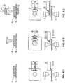
- FIG. 6 the connection method with integrated supply of the welding auxiliary joining part E will be described.
- the welding assist joining part E is supplied to the end position 22 (step S1).
- Figure 6.1 shows the material layers A, B without an overlying welding auxiliary joining part E. Die End position 22 of the Elementzu slaughterleton 10 is not yet between the punch 4 and 5 abutment arranged.
- the actuator 28 now moves the Sch Strukturettidsyoggeteil E under the punch 4 (step S2).
- the punch 4 forms an electrode in the later welding process, preferably the negative or ground electrode.
- the flap 34 is opened and the clamping jaw levers 18, 19 move the welding auxiliary joining part E under the punch 4, preferably to the movement line B 1 .
- the clamping jaw lever 19 is preferably unlocked with this movement in order to be able to release the welding auxiliary joining part E later.
- next step moves the element feeding device 10 by the actuator 14 against the joining direction R F until the Sch relienoses Stahl E rests with its head on the electrode punch 4.
- This is preferably carried out path-controlled on fixed waypoints.
- the waypoints are adjusted.
- the position of the Sch relienoses Stahlelements E force controlled to approach a current threshold in the servo motor drive of the actuator 14 of the element feed device 10.
- a further preferred embodiment is to deliver the punch 4 via the drive 2 to the auxiliary welding element E positioned on the line of movement B 1 .
- Sufficient contact between the welding auxiliary joining element E and the stamp 4 can be recognized by means of a force sensor in the setting / welding device 1 or by means of a detected current value of the drive 2 of the setting / welding device 1.
- a superposed force / displacement control This additionally allows a check whether the Sch relieoshegeelement E has actually been positioned between the punch 4 and 5 abutment and preferably of which length it has.
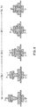
- FIG. 7 describes the mechanical and electrical loads preferably applied during the bonding process.
- F denotes the force on the punch 4.
- the step S of the connection method is indicated. Therefore, if in step S3 the welding auxiliary joining part E is displaced against the stamp 4, this can be detected as a force value (see also FIG Fig. 6.3 ).
- the setting welding device 1 moves as far as the punch 4 in the direction of abutment 5 until the Sch relienoss Schogeteil E with its head facing away on the cover-layer joint partner, so the material layer A, touches , Further, the traveling distance of the punch 4 is limited by obtaining a preset clamping force of the punch 4 with which the welding auxiliary joining member E is pressed on the sheet material A between the punch 4 and the abutment 5 (see step S4).
- the control for achieving this clamping position of the Sch relieosglageteils is carried out according to a preferred embodiment path-controlled or force-controlled and controlled away according to another preferred embodiment.
- the central control of the setting-welding device 1 sends a corresponding signal to the control of the element feed 10. It is also preferred in that, as part of the clamping, the tip of the welding auxiliary joining part E is impressively pressed into the material layer A facing the tip. This stabilizes the clamped Sch spall E and preferably does not adversely affect the subsequent connection.
- step S5 the element feeder 10 is relieved and the Sch requirementsosyoggeteil E released.
- the jaw levers 18,19 are opened (see above) or simply pulled off the clamped Sch characteristicsakustinum E (see Fig. 6.5 ). Accordingly, the force in step S5 (see FIG Fig. 7 ).
- a new loading of the end position 22 can take place.
- step S6 -1 is preferably supported by an electric current flow, as can be seen in FIG.
- the electrical current flow preferably reduces the hardness of the material layer A as a result of material heating, while the Sch relieos spageteil E is driven to the material layer B.
- FIG. 7 shows (see S6 - 2).
- step S6-3 the welding of the material layer B with the welding auxiliary joining part E takes place.
- the duration of the welding process is preferably determined by a period of time.
- the path of the punch 4 during welding is detected. If this exceeds a threshold sinking distance of the welding auxiliary joining part E and thus of the punch 4, then the welding process is ended.
- step S7 the connection is de-energized, wherein the joint is further mechanically clamped between the punch 4 and the counter bearing 5.
- step S8 - 9 the punch 4 and the abutment 5 are relieved and the connection is removed, as in FIGS Figures 6.8 and 6.9 is shown.
- the welding auxiliary joining part E ' (not shown) preferably has at its head a functional end projecting away from the shaft of the welding auxiliary joining part E'.
- the functional end comprises a fastening structure, such as, for example, a threaded ridge, a threaded sleeve, a ball head or a latching structure, or a design element.
- the functional end is arranged coaxially to the shaft with respect to the longitudinal axis of the welding auxiliary joining part E '.
- an annular circumferential radial projection extends in the transition region between the shaft and functional end. The annular circumferential radial projection forms an undercut transverse to the joining direction R F.
- the stamp 4 '(not shown) in adaptation to the welding auxiliary joining part E' has a central opening with a ring-like abutment or pressure surface.
Landscapes
- Engineering & Computer Science (AREA)
- Mechanical Engineering (AREA)
- Resistance Welding (AREA)
- Automatic Assembly (AREA)
- Connection Of Plates (AREA)
- Lining Or Joining Of Plastics Or The Like (AREA)
Applications Claiming Priority (2)
| Application Number | Priority Date | Filing Date | Title |
|---|---|---|---|
| DE102016101557 | 2016-01-28 | ||
| DE102016101755.8A DE102016101755A1 (de) | 2016-02-01 | 2016-02-01 | Elementzuführeinrichtung eines Setz-Schweiß-Geräts, ein Setz-Schweiß-Gerät sowie ein Verbindungsverfahren in Form eines mechanisch-thermischen Setz-Schweiß-Prozesses |
Publications (4)
| Publication Number | Publication Date |
|---|---|
| EP3199288A2 true EP3199288A2 (fr) | 2017-08-02 |
| EP3199288A3 EP3199288A3 (fr) | 2018-02-28 |
| EP3199288B1 EP3199288B1 (fr) | 2024-04-03 |
| EP3199288B8 EP3199288B8 (fr) | 2024-05-29 |
Family
ID=57914750
Family Applications (1)
| Application Number | Title | Priority Date | Filing Date |
|---|---|---|---|
| EP17152927.4A Active EP3199288B8 (fr) | 2016-01-28 | 2017-01-24 | Dispositif d'alimentation en éléments d'un appareil de placement et de soudage, appareil de placement et de soudage et procédé d'assemblage sous la forme d'un processus de placement et de soudage mécano-thermique |
Country Status (4)
| Country | Link |
|---|---|
| US (1) | US10766096B2 (fr) |
| EP (1) | EP3199288B8 (fr) |
| JP (1) | JP6470325B2 (fr) |
| CN (1) | CN107030366B (fr) |
Cited By (2)
| Publication number | Priority date | Publication date | Assignee | Title |
|---|---|---|---|---|
| EP3812062A1 (fr) * | 2019-10-18 | 2021-04-28 | Eckold GmbH & Co. KG | Outil d'assemblage de composants |
| EP3858532A1 (fr) | 2020-01-29 | 2021-08-04 | Böllhoff Verbindungstechnik GmbH | Dispositif d'alimentation en élément pour un appareil de placement et de soudage, un réseau d'élément et ensemble de mise à niveau pour le dispositif de placement et de soudage et procédé d'alimentation correspondant d'une pièce d'assemblage auxiliaire par soudage |
Families Citing this family (5)
| Publication number | Priority date | Publication date | Assignee | Title |
|---|---|---|---|---|
| US10807148B2 (en) * | 2017-06-20 | 2020-10-20 | Fca Us Llc | Upset protrusion joining and forging gun therefor |
| CN109078338B (zh) * | 2018-07-23 | 2020-10-16 | 青岛鑫集美工艺品有限公司 | 一种铆眼方法 |
| ES2899527B2 (es) * | 2020-09-11 | 2023-01-05 | Bosco Tecnoindustria S L | Sistema de alimentacion de piezas para prensas de soldadura por resistencia y prensa de soldadura que comprende dicho sistema |
| CN114226943B (zh) * | 2022-01-06 | 2022-09-27 | 中国科学院上海光学精密机械研究所 | 一种焊接料片、输送系统、焊接装置及方法 |
| CN118989544B (zh) * | 2024-10-23 | 2024-12-27 | 苏州腾欣汽车零部件有限公司 | 一种可自锁的焊枪及其磨损补偿方法 |
Citations (5)
| Publication number | Priority date | Publication date | Assignee | Title |
|---|---|---|---|---|
| DE4318908C1 (de) | 1993-06-07 | 1994-08-18 | Daimler Benz Ag | Schweißvorrichtung zum widerstandselektrischen Anschweißen von Kleinteilen mit integrierter Zuführung der Kleinteile |
| US5492262A (en) | 1994-05-11 | 1996-02-20 | Pascarelli; Douglas A. | Device for supporting a plurality of nails in a coupled fashion for automatically feeding such nails from a container |
| DE102004039398A1 (de) | 2004-08-13 | 2006-02-23 | Ejot Gmbh & Co. Kg | Futter zur Halterung von Befestigungselementen für eine Reibschweißverbindung |
| DE102010060141A1 (de) | 2010-10-25 | 2012-04-26 | Ejot Gmbh & Co. Kg | Vorrichtung zur Positionierung und Zuführung von Befestigungselementen |
| DE102013207284A1 (de) | 2013-04-22 | 2014-10-23 | Böllhoff Verbindungstechnik GmbH | Setz-Schweiß-Gerät, modulare Komponenten davon sowie ein mit ihm durchführbares kontinuierliches Verbindungsverfahren |
Family Cites Families (23)
| Publication number | Priority date | Publication date | Assignee | Title |
|---|---|---|---|---|
| US1333414A (en) | 1918-03-04 | 1920-03-09 | Judson L Thomson Mfg Co | Feeding mechanism for rivet and cap setting machines |
| DE954187C (de) * | 1954-05-15 | 1956-12-13 | Asea Ab | Vorrichtung zum Festschweissen von einem oder gleichzeitig mehreren Bolzen an ebene oder gekruemmte Flaechen |
| JPS61235082A (ja) * | 1985-04-11 | 1986-10-20 | Seiwa Yoko Kk | 溶接機へのプロジエクシヨン付ボルト供給装置 |
| DE3602119A1 (de) * | 1986-01-24 | 1987-07-30 | Chibret Pharmazeutische Ges Mb | Verschlusszaehler |
| JPS62212078A (ja) | 1986-03-12 | 1987-09-18 | Toyota Motor Corp | ナツト溶接のスパツタ付着防止方法 |
| JPH0622553Y2 (ja) * | 1989-12-19 | 1994-06-15 | トヨタ自動車株式会社 | 溶接部品の自動供給装置 |
| JP3148846B2 (ja) | 1994-02-21 | 2001-03-26 | 好高 青山 | 供給ロッド等にプロジェクションボルトを挿入するための供給部材 |
| DE9406687U1 (de) | 1994-04-21 | 1995-08-17 | Emhart Inc., Newark, Del. | Zufuhreinrichtung für längliche, insbesondere mit Kopf ausgebildete Bauteile |
| JP3326490B2 (ja) | 1996-03-09 | 2002-09-24 | 好高 青山 | プロジェクションナットの溶接装置と溶接方法 |
| JP3263754B2 (ja) | 1997-02-13 | 2002-03-11 | 矢嶋工業株式会社 | スタッドボルト供給装置 |
| JP2002018650A (ja) | 2000-06-29 | 2002-01-22 | Seki Kogyo Kk | ボルトフィーダ |
| JP2002321064A (ja) | 2001-04-27 | 2002-11-05 | Yajima Giken Kk | ナットフィーダの供給ヘッド |
| JP4665194B2 (ja) | 2005-05-27 | 2011-04-06 | 好高 青山 | 小径軸状部品の電気抵抗溶接方法および装置 |
| JP2007167947A (ja) | 2005-12-19 | 2007-07-05 | Yoshitaka Aoyama | 軸状部品の供給装置 |
| JP5057033B2 (ja) | 2007-01-08 | 2012-10-24 | 好高 青山 | 電気抵抗溶接機用部品供給装置 |
| US8468671B2 (en) | 2007-11-02 | 2013-06-25 | Electroimpact, Inc. | System for loading collars onto bolts in large-scale manufacturing operations |
| DE102009024433A1 (de) | 2009-06-05 | 2010-12-09 | Newfrey Llc, Newark | Vereinzelungsschieber für eine Vorrichtung zum Zuführen eines Verbindungselements |
| JP5468453B2 (ja) | 2010-04-22 | 2014-04-09 | 株式会社エフ・シー・シー | リベットセット装置 |
| CN103180082B (zh) * | 2010-09-06 | 2016-08-10 | 本田技研工业株式会社 | 焊接方法和焊接装置 |
| JP2013066978A (ja) | 2011-09-22 | 2013-04-18 | Yajima Giken Inc | 小物部品の供給装置 |
| EP2671662B1 (fr) * | 2012-06-05 | 2015-08-12 | Gestamp Ingenieria Europa Sur, S.L. | Dispositif de soudage par résistance |
| MX378657B (es) * | 2014-07-02 | 2025-03-10 | Doben Ltd | Sistema y metodo con transportador de arrastre para soldadura de produccion de alta velocidad. |
| KR102319841B1 (ko) * | 2015-09-16 | 2021-10-29 | 하우매트 에어로스페이스 인코포레이티드 | 리벳 공급 장치 |
-
2017
- 2017-01-24 EP EP17152927.4A patent/EP3199288B8/fr active Active
- 2017-01-27 US US15/417,290 patent/US10766096B2/en active Active
- 2017-01-27 JP JP2017013709A patent/JP6470325B2/ja active Active
- 2017-02-03 CN CN201710063180.1A patent/CN107030366B/zh active Active
Patent Citations (5)
| Publication number | Priority date | Publication date | Assignee | Title |
|---|---|---|---|---|
| DE4318908C1 (de) | 1993-06-07 | 1994-08-18 | Daimler Benz Ag | Schweißvorrichtung zum widerstandselektrischen Anschweißen von Kleinteilen mit integrierter Zuführung der Kleinteile |
| US5492262A (en) | 1994-05-11 | 1996-02-20 | Pascarelli; Douglas A. | Device for supporting a plurality of nails in a coupled fashion for automatically feeding such nails from a container |
| DE102004039398A1 (de) | 2004-08-13 | 2006-02-23 | Ejot Gmbh & Co. Kg | Futter zur Halterung von Befestigungselementen für eine Reibschweißverbindung |
| DE102010060141A1 (de) | 2010-10-25 | 2012-04-26 | Ejot Gmbh & Co. Kg | Vorrichtung zur Positionierung und Zuführung von Befestigungselementen |
| DE102013207284A1 (de) | 2013-04-22 | 2014-10-23 | Böllhoff Verbindungstechnik GmbH | Setz-Schweiß-Gerät, modulare Komponenten davon sowie ein mit ihm durchführbares kontinuierliches Verbindungsverfahren |
Cited By (3)
| Publication number | Priority date | Publication date | Assignee | Title |
|---|---|---|---|---|
| EP3812062A1 (fr) * | 2019-10-18 | 2021-04-28 | Eckold GmbH & Co. KG | Outil d'assemblage de composants |
| EP3858532A1 (fr) | 2020-01-29 | 2021-08-04 | Böllhoff Verbindungstechnik GmbH | Dispositif d'alimentation en élément pour un appareil de placement et de soudage, un réseau d'élément et ensemble de mise à niveau pour le dispositif de placement et de soudage et procédé d'alimentation correspondant d'une pièce d'assemblage auxiliaire par soudage |
| US11883900B2 (en) | 2020-01-29 | 2024-01-30 | Böllhoff Verbindungstechnik GmbH | Element supply apparatus for a setting welding device, an element nest and a retrofit kit for the setting welding device as well as corresponding supply methods of a welding auxiliary joining part |
Also Published As
| Publication number | Publication date |
|---|---|
| CN107030366A (zh) | 2017-08-11 |
| EP3199288B8 (fr) | 2024-05-29 |
| US10766096B2 (en) | 2020-09-08 |
| CN107030366B (zh) | 2019-11-19 |
| EP3199288A3 (fr) | 2018-02-28 |
| JP2017148867A (ja) | 2017-08-31 |
| EP3199288B1 (fr) | 2024-04-03 |
| US20170216957A1 (en) | 2017-08-03 |
| JP6470325B2 (ja) | 2019-02-13 |
Similar Documents
| Publication | Publication Date | Title |
|---|---|---|
| EP3199288B1 (fr) | Dispositif d'alimentation en éléments d'un appareil de placement et de soudage, appareil de placement et de soudage et procédé d'assemblage sous la forme d'un processus de placement et de soudage mécano-thermique | |
| EP2988902B1 (fr) | Appareil de placement et de soudage, composants modulaires dudit appareil et procédé d'assemblage en continu pouvant être mis en uvre au moyen dudit appareil | |
| EP3378581B1 (fr) | Dispositif d'assemblage en plusieurs étapes et procédé d'assemblage correspondant | |
| EP2488316B1 (fr) | Dispositif de fixation d'au moins deux pièces | |
| DE102004012786A1 (de) | Fügevorrichtung zum Befestigen von kleinteiligen Bauelementen an einer Trägerfläche durch Kleben | |
| EP3505270B1 (fr) | Unité de frappe pour un dispositif de poinçonnage, dispositif de poinçonnage et procédé de fabrication d'un tel dispositif de poinçonnage | |
| EP1915270A1 (fr) | Procede pour assembler le bord de profils d'etancheite et dispositif pour le mettre en oeuvre | |
| DE102017203943A1 (de) | Setzeinheit und Verfahren zum Setzen eines Verbindungselements an einem Werkstück | |
| WO2016169668A1 (fr) | Dispositif d'assemblage | |
| DE102016101755A1 (de) | Elementzuführeinrichtung eines Setz-Schweiß-Geräts, ein Setz-Schweiß-Gerät sowie ein Verbindungsverfahren in Form eines mechanisch-thermischen Setz-Schweiß-Prozesses | |
| EP3096899B1 (fr) | Dispositif d'assemblage, de préférence de rivetage, clinchage ou poinçonnage | |
| EP3681655B1 (fr) | Dispositif ainsi que procédé pour poser un élément de liaison sur une pièce | |
| DE102015007295B3 (de) | Setzvorrichtung | |
| DE102010000170B4 (de) | Vorrichtung zum Lösen einer Punktschweißspitze | |
| EP3552729B1 (fr) | Dispositif d'installation de rivets auto-poinçonneurs | |
| WO2007112720A1 (fr) | Procédé et dispositif outil de formage | |
| DE10258928A1 (de) | Taumelfügevorrichtung | |
| DE60212359T2 (de) | Stanznietsetzmaschine | |
| EP3858532A1 (fr) | Dispositif d'alimentation en élément pour un appareil de placement et de soudage, un réseau d'élément et ensemble de mise à niveau pour le dispositif de placement et de soudage et procédé d'alimentation correspondant d'une pièce d'assemblage auxiliaire par soudage | |
| DE102011121692A1 (de) | Fügeelement-Zuführverfahren, -Halteanordnung und Fügevorrichtung | |
| EP3956084B1 (fr) | Tête de pose, presse pour tôle ou dispositif de pose pourvu de cette tête de pose et procédé d'assemblage d'un élément d'assemblage avec ladite tête de pose | |
| DE102016224517A1 (de) | Prägestation | |
| DE102016005850B4 (de) | Verfahren und Vorrichtung zum Fügen wenigstens zweier Bauteile, insbesondere für ein Kraftfahrzeug | |
| DE10055879A1 (de) | Anordnung zur Befestigung einer Grundplatte eines Fensterhebers an einer Kraftfahrzeug-Karosserie | |
| DE102014104641B4 (de) | Schweißelektrodeneinheit und Verfahren zum Buckelschweißen |
Legal Events
| Date | Code | Title | Description |
|---|---|---|---|
| PUAI | Public reference made under article 153(3) epc to a published international application that has entered the european phase |
Free format text: ORIGINAL CODE: 0009012 |
|
| STAA | Information on the status of an ep patent application or granted ep patent |
Free format text: STATUS: THE APPLICATION HAS BEEN PUBLISHED |
|
| AK | Designated contracting states |
Kind code of ref document: A2 Designated state(s): AL AT BE BG CH CY CZ DE DK EE ES FI FR GB GR HR HU IE IS IT LI LT LU LV MC MK MT NL NO PL PT RO RS SE SI SK SM TR |
|
| AX | Request for extension of the european patent |
Extension state: BA ME |
|
| RIC1 | Information provided on ipc code assigned before grant |
Ipc: B23K 10/02 20060101AFI20170828BHEP Ipc: B21J 15/08 20060101ALI20170828BHEP Ipc: B23K 11/10 20060101ALI20170828BHEP |
|
| PUAL | Search report despatched |
Free format text: ORIGINAL CODE: 0009013 |
|
| AK | Designated contracting states |
Kind code of ref document: A3 Designated state(s): AL AT BE BG CH CY CZ DE DK EE ES FI FR GB GR HR HU IE IS IT LI LT LU LV MC MK MT NL NO PL PT RO RS SE SI SK SM TR |
|
| AX | Request for extension of the european patent |
Extension state: BA ME |
|
| RIC1 | Information provided on ipc code assigned before grant |
Ipc: B21J 15/08 20060101ALI20180119BHEP Ipc: B23K 11/10 20060101ALI20180119BHEP Ipc: B23K 11/00 20060101ALI20180119BHEP Ipc: B23K 10/02 20060101AFI20180119BHEP |
|
| STAA | Information on the status of an ep patent application or granted ep patent |
Free format text: STATUS: REQUEST FOR EXAMINATION WAS MADE |
|
| 17P | Request for examination filed |
Effective date: 20180814 |
|
| RBV | Designated contracting states (corrected) |
Designated state(s): AL AT BE BG CH CY CZ DE DK EE ES FI FR GB GR HR HU IE IS IT LI LT LU LV MC MK MT NL NO PL PT RO RS SE SI SK SM TR |
|
| STAA | Information on the status of an ep patent application or granted ep patent |
Free format text: STATUS: EXAMINATION IS IN PROGRESS |
|
| 17Q | First examination report despatched |
Effective date: 20210309 |
|
| GRAP | Despatch of communication of intention to grant a patent |
Free format text: ORIGINAL CODE: EPIDOSNIGR1 |
|
| STAA | Information on the status of an ep patent application or granted ep patent |
Free format text: STATUS: GRANT OF PATENT IS INTENDED |
|
| INTG | Intention to grant announced |
Effective date: 20230616 |
|
| GRAJ | Information related to disapproval of communication of intention to grant by the applicant or resumption of examination proceedings by the epo deleted |
Free format text: ORIGINAL CODE: EPIDOSDIGR1 |
|
| STAA | Information on the status of an ep patent application or granted ep patent |
Free format text: STATUS: EXAMINATION IS IN PROGRESS |
|
| INTC | Intention to grant announced (deleted) | ||
| GRAP | Despatch of communication of intention to grant a patent |
Free format text: ORIGINAL CODE: EPIDOSNIGR1 |
|
| STAA | Information on the status of an ep patent application or granted ep patent |
Free format text: STATUS: GRANT OF PATENT IS INTENDED |
|
| INTG | Intention to grant announced |
Effective date: 20231122 |
|
| GRAS | Grant fee paid |
Free format text: ORIGINAL CODE: EPIDOSNIGR3 |
|
| GRAA | (expected) grant |
Free format text: ORIGINAL CODE: 0009210 |
|
| STAA | Information on the status of an ep patent application or granted ep patent |
Free format text: STATUS: THE PATENT HAS BEEN GRANTED |
|
| GRAT | Correction requested after decision to grant or after decision to maintain patent in amended form |
Free format text: ORIGINAL CODE: EPIDOSNCDEC |
|
| AK | Designated contracting states |
Kind code of ref document: B1 Designated state(s): AL AT BE BG CH CY CZ DE DK EE ES FI FR GB GR HR HU IE IS IT LI LT LU LV MC MK MT NL NO PL PT RO RS SE SI SK SM TR |
|
| REG | Reference to a national code |
Ref country code: GB Ref legal event code: FG4D Free format text: NOT ENGLISH |
|
| REG | Reference to a national code |
Ref country code: CH Ref legal event code: EP |
|
| REG | Reference to a national code |
Ref country code: DE Ref legal event code: R096 Ref document number: 502017015976 Country of ref document: DE |
|
| REG | Reference to a national code |
Ref country code: IE Ref legal event code: FG4D Free format text: LANGUAGE OF EP DOCUMENT: GERMAN |
|
| RIN2 | Information on inventor provided after grant (corrected) |
Inventor name: SCHMIDT, KONSTANTIN Inventor name: HARTWIG-BIGLAU, SERGEJ |
|
| REG | Reference to a national code |
Ref country code: CH Ref legal event code: PK Free format text: BERICHTIGUNGEN Ref country code: CH Ref legal event code: PK Free format text: TITEL Ref country code: CH Ref legal event code: PK Free format text: DIE PUBLIKATION VOM 27.03.2024 WURDE AM 24.04.2024 IRRTUEMLICHERWEISE ERNEUT PUBLIZIERT. LA PUBLICATION DU 27.03.2024 A ETE REPUBLIEE PAR ERREUR LE 24.04.2024. LA PUBBLICAZIONE DEL 27.03.2024 E STATA ERRONEAMENTE RIPUBBLICATA IL 24.04.2024. |
|
| REG | Reference to a national code |
Ref country code: CH Ref legal event code: PK Free format text: BERICHTIGUNG B8 |
|
| REG | Reference to a national code |
Ref country code: LT Ref legal event code: MG9D |
|
| REG | Reference to a national code |
Ref country code: NL Ref legal event code: MP Effective date: 20240403 |
|
| PG25 | Lapsed in a contracting state [announced via postgrant information from national office to epo] |
Ref country code: NL Free format text: LAPSE BECAUSE OF FAILURE TO SUBMIT A TRANSLATION OF THE DESCRIPTION OR TO PAY THE FEE WITHIN THE PRESCRIBED TIME-LIMIT Effective date: 20240403 |
|
| PG25 | Lapsed in a contracting state [announced via postgrant information from national office to epo] |
Ref country code: NL Free format text: LAPSE BECAUSE OF FAILURE TO SUBMIT A TRANSLATION OF THE DESCRIPTION OR TO PAY THE FEE WITHIN THE PRESCRIBED TIME-LIMIT Effective date: 20240403 |
|
| PG25 | Lapsed in a contracting state [announced via postgrant information from national office to epo] |
Ref country code: IS Free format text: LAPSE BECAUSE OF FAILURE TO SUBMIT A TRANSLATION OF THE DESCRIPTION OR TO PAY THE FEE WITHIN THE PRESCRIBED TIME-LIMIT Effective date: 20240803 |
|
| PG25 | Lapsed in a contracting state [announced via postgrant information from national office to epo] |
Ref country code: BG Free format text: LAPSE BECAUSE OF FAILURE TO SUBMIT A TRANSLATION OF THE DESCRIPTION OR TO PAY THE FEE WITHIN THE PRESCRIBED TIME-LIMIT Effective date: 20240403 |
|
| PG25 | Lapsed in a contracting state [announced via postgrant information from national office to epo] |
Ref country code: HR Free format text: LAPSE BECAUSE OF FAILURE TO SUBMIT A TRANSLATION OF THE DESCRIPTION OR TO PAY THE FEE WITHIN THE PRESCRIBED TIME-LIMIT Effective date: 20240403 Ref country code: FI Free format text: LAPSE BECAUSE OF FAILURE TO SUBMIT A TRANSLATION OF THE DESCRIPTION OR TO PAY THE FEE WITHIN THE PRESCRIBED TIME-LIMIT Effective date: 20240403 |
|
| PG25 | Lapsed in a contracting state [announced via postgrant information from national office to epo] |
Ref country code: GR Free format text: LAPSE BECAUSE OF FAILURE TO SUBMIT A TRANSLATION OF THE DESCRIPTION OR TO PAY THE FEE WITHIN THE PRESCRIBED TIME-LIMIT Effective date: 20240704 |
|
| PG25 | Lapsed in a contracting state [announced via postgrant information from national office to epo] |
Ref country code: PT Free format text: LAPSE BECAUSE OF FAILURE TO SUBMIT A TRANSLATION OF THE DESCRIPTION OR TO PAY THE FEE WITHIN THE PRESCRIBED TIME-LIMIT Effective date: 20240805 |
|
| PG25 | Lapsed in a contracting state [announced via postgrant information from national office to epo] |
Ref country code: ES Free format text: LAPSE BECAUSE OF FAILURE TO SUBMIT A TRANSLATION OF THE DESCRIPTION OR TO PAY THE FEE WITHIN THE PRESCRIBED TIME-LIMIT Effective date: 20240403 |
|
| PG25 | Lapsed in a contracting state [announced via postgrant information from national office to epo] |
Ref country code: CZ Free format text: LAPSE BECAUSE OF FAILURE TO SUBMIT A TRANSLATION OF THE DESCRIPTION OR TO PAY THE FEE WITHIN THE PRESCRIBED TIME-LIMIT Effective date: 20240403 |
|
| PG25 | Lapsed in a contracting state [announced via postgrant information from national office to epo] |
Ref country code: PL Free format text: LAPSE BECAUSE OF FAILURE TO SUBMIT A TRANSLATION OF THE DESCRIPTION OR TO PAY THE FEE WITHIN THE PRESCRIBED TIME-LIMIT Effective date: 20240403 |
|
| PG25 | Lapsed in a contracting state [announced via postgrant information from national office to epo] |
Ref country code: LV Free format text: LAPSE BECAUSE OF FAILURE TO SUBMIT A TRANSLATION OF THE DESCRIPTION OR TO PAY THE FEE WITHIN THE PRESCRIBED TIME-LIMIT Effective date: 20240403 |
|
| PG25 | Lapsed in a contracting state [announced via postgrant information from national office to epo] |
Ref country code: PT Free format text: LAPSE BECAUSE OF FAILURE TO SUBMIT A TRANSLATION OF THE DESCRIPTION OR TO PAY THE FEE WITHIN THE PRESCRIBED TIME-LIMIT Effective date: 20240805 Ref country code: PL Free format text: LAPSE BECAUSE OF FAILURE TO SUBMIT A TRANSLATION OF THE DESCRIPTION OR TO PAY THE FEE WITHIN THE PRESCRIBED TIME-LIMIT Effective date: 20240403 Ref country code: NO Free format text: LAPSE BECAUSE OF FAILURE TO SUBMIT A TRANSLATION OF THE DESCRIPTION OR TO PAY THE FEE WITHIN THE PRESCRIBED TIME-LIMIT Effective date: 20240703 Ref country code: LV Free format text: LAPSE BECAUSE OF FAILURE TO SUBMIT A TRANSLATION OF THE DESCRIPTION OR TO PAY THE FEE WITHIN THE PRESCRIBED TIME-LIMIT Effective date: 20240403 Ref country code: IS Free format text: LAPSE BECAUSE OF FAILURE TO SUBMIT A TRANSLATION OF THE DESCRIPTION OR TO PAY THE FEE WITHIN THE PRESCRIBED TIME-LIMIT Effective date: 20240803 Ref country code: HR Free format text: LAPSE BECAUSE OF FAILURE TO SUBMIT A TRANSLATION OF THE DESCRIPTION OR TO PAY THE FEE WITHIN THE PRESCRIBED TIME-LIMIT Effective date: 20240403 Ref country code: GR Free format text: LAPSE BECAUSE OF FAILURE TO SUBMIT A TRANSLATION OF THE DESCRIPTION OR TO PAY THE FEE WITHIN THE PRESCRIBED TIME-LIMIT Effective date: 20240704 Ref country code: FI Free format text: LAPSE BECAUSE OF FAILURE TO SUBMIT A TRANSLATION OF THE DESCRIPTION OR TO PAY THE FEE WITHIN THE PRESCRIBED TIME-LIMIT Effective date: 20240403 Ref country code: ES Free format text: LAPSE BECAUSE OF FAILURE TO SUBMIT A TRANSLATION OF THE DESCRIPTION OR TO PAY THE FEE WITHIN THE PRESCRIBED TIME-LIMIT Effective date: 20240403 Ref country code: CZ Free format text: LAPSE BECAUSE OF FAILURE TO SUBMIT A TRANSLATION OF THE DESCRIPTION OR TO PAY THE FEE WITHIN THE PRESCRIBED TIME-LIMIT Effective date: 20240403 Ref country code: BG Free format text: LAPSE BECAUSE OF FAILURE TO SUBMIT A TRANSLATION OF THE DESCRIPTION OR TO PAY THE FEE WITHIN THE PRESCRIBED TIME-LIMIT Effective date: 20240403 Ref country code: RS Free format text: LAPSE BECAUSE OF FAILURE TO SUBMIT A TRANSLATION OF THE DESCRIPTION OR TO PAY THE FEE WITHIN THE PRESCRIBED TIME-LIMIT Effective date: 20240703 |
|
| REG | Reference to a national code |
Ref country code: DE Ref legal event code: R097 Ref document number: 502017015976 Country of ref document: DE |
|
| PG25 | Lapsed in a contracting state [announced via postgrant information from national office to epo] |
Ref country code: DK Free format text: LAPSE BECAUSE OF FAILURE TO SUBMIT A TRANSLATION OF THE DESCRIPTION OR TO PAY THE FEE WITHIN THE PRESCRIBED TIME-LIMIT Effective date: 20240403 |
|
| PG25 | Lapsed in a contracting state [announced via postgrant information from national office to epo] |
Ref country code: EE Free format text: LAPSE BECAUSE OF FAILURE TO SUBMIT A TRANSLATION OF THE DESCRIPTION OR TO PAY THE FEE WITHIN THE PRESCRIBED TIME-LIMIT Effective date: 20240403 |
|
| PG25 | Lapsed in a contracting state [announced via postgrant information from national office to epo] |
Ref country code: SK Free format text: LAPSE BECAUSE OF FAILURE TO SUBMIT A TRANSLATION OF THE DESCRIPTION OR TO PAY THE FEE WITHIN THE PRESCRIBED TIME-LIMIT Effective date: 20240403 Ref country code: RO Free format text: LAPSE BECAUSE OF FAILURE TO SUBMIT A TRANSLATION OF THE DESCRIPTION OR TO PAY THE FEE WITHIN THE PRESCRIBED TIME-LIMIT Effective date: 20240403 |
|
| PG25 | Lapsed in a contracting state [announced via postgrant information from national office to epo] |
Ref country code: SM Free format text: LAPSE BECAUSE OF FAILURE TO SUBMIT A TRANSLATION OF THE DESCRIPTION OR TO PAY THE FEE WITHIN THE PRESCRIBED TIME-LIMIT Effective date: 20240403 |
|
| PG25 | Lapsed in a contracting state [announced via postgrant information from national office to epo] |
Ref country code: SM Free format text: LAPSE BECAUSE OF FAILURE TO SUBMIT A TRANSLATION OF THE DESCRIPTION OR TO PAY THE FEE WITHIN THE PRESCRIBED TIME-LIMIT Effective date: 20240403 Ref country code: SK Free format text: LAPSE BECAUSE OF FAILURE TO SUBMIT A TRANSLATION OF THE DESCRIPTION OR TO PAY THE FEE WITHIN THE PRESCRIBED TIME-LIMIT Effective date: 20240403 Ref country code: RO Free format text: LAPSE BECAUSE OF FAILURE TO SUBMIT A TRANSLATION OF THE DESCRIPTION OR TO PAY THE FEE WITHIN THE PRESCRIBED TIME-LIMIT Effective date: 20240403 Ref country code: EE Free format text: LAPSE BECAUSE OF FAILURE TO SUBMIT A TRANSLATION OF THE DESCRIPTION OR TO PAY THE FEE WITHIN THE PRESCRIBED TIME-LIMIT Effective date: 20240403 Ref country code: DK Free format text: LAPSE BECAUSE OF FAILURE TO SUBMIT A TRANSLATION OF THE DESCRIPTION OR TO PAY THE FEE WITHIN THE PRESCRIBED TIME-LIMIT Effective date: 20240403 |
|
| PLBE | No opposition filed within time limit |
Free format text: ORIGINAL CODE: 0009261 |
|
| STAA | Information on the status of an ep patent application or granted ep patent |
Free format text: STATUS: NO OPPOSITION FILED WITHIN TIME LIMIT |
|
| 26N | No opposition filed |
Effective date: 20250106 |
|
| PG25 | Lapsed in a contracting state [announced via postgrant information from national office to epo] |
Ref country code: SI Free format text: LAPSE BECAUSE OF FAILURE TO SUBMIT A TRANSLATION OF THE DESCRIPTION OR TO PAY THE FEE WITHIN THE PRESCRIBED TIME-LIMIT Effective date: 20240403 |
|
| REG | Reference to a national code |
Ref country code: CH Ref legal event code: PL |
|
| PG25 | Lapsed in a contracting state [announced via postgrant information from national office to epo] |
Ref country code: SE Free format text: LAPSE BECAUSE OF FAILURE TO SUBMIT A TRANSLATION OF THE DESCRIPTION OR TO PAY THE FEE WITHIN THE PRESCRIBED TIME-LIMIT Effective date: 20240403 |
|
| PG25 | Lapsed in a contracting state [announced via postgrant information from national office to epo] |
Ref country code: MC Free format text: LAPSE BECAUSE OF FAILURE TO SUBMIT A TRANSLATION OF THE DESCRIPTION OR TO PAY THE FEE WITHIN THE PRESCRIBED TIME-LIMIT Effective date: 20240403 Ref country code: LU Free format text: LAPSE BECAUSE OF NON-PAYMENT OF DUE FEES Effective date: 20250124 |
|
| PG25 | Lapsed in a contracting state [announced via postgrant information from national office to epo] |
Ref country code: BE Free format text: LAPSE BECAUSE OF NON-PAYMENT OF DUE FEES Effective date: 20250131 |
|
| PG25 | Lapsed in a contracting state [announced via postgrant information from national office to epo] |
Ref country code: CH Free format text: LAPSE BECAUSE OF NON-PAYMENT OF DUE FEES Effective date: 20250131 |
|
| REG | Reference to a national code |
Ref country code: BE Ref legal event code: MM Effective date: 20250131 |
|
| PG25 | Lapsed in a contracting state [announced via postgrant information from national office to epo] |
Ref country code: IE Free format text: LAPSE BECAUSE OF NON-PAYMENT OF DUE FEES Effective date: 20250124 |
|
| PG25 | Lapsed in a contracting state [announced via postgrant information from national office to epo] |
Ref country code: IT Free format text: LAPSE BECAUSE OF FAILURE TO SUBMIT A TRANSLATION OF THE DESCRIPTION OR TO PAY THE FEE WITHIN THE PRESCRIBED TIME-LIMIT Effective date: 20240403 |
|
| REG | Reference to a national code |
Ref country code: AT Ref legal event code: MM01 Ref document number: 1671734 Country of ref document: AT Kind code of ref document: T Effective date: 20250124 |
|
| PGFP | Annual fee paid to national office [announced via postgrant information from national office to epo] |
Ref country code: GB Payment date: 20260122 Year of fee payment: 10 |
|
| PGFP | Annual fee paid to national office [announced via postgrant information from national office to epo] |
Ref country code: DE Payment date: 20260318 Year of fee payment: 10 |
|
| PG25 | Lapsed in a contracting state [announced via postgrant information from national office to epo] |
Ref country code: AT Free format text: LAPSE BECAUSE OF NON-PAYMENT OF DUE FEES Effective date: 20250124 |
|
| PGFP | Annual fee paid to national office [announced via postgrant information from national office to epo] |
Ref country code: FR Payment date: 20260128 Year of fee payment: 10 |