EP3199408A1 - Steuerungsvorrichtung und steuerungsverfahren für eine elektronische vorrichtung in einem fahrzeug - Google Patents
Steuerungsvorrichtung und steuerungsverfahren für eine elektronische vorrichtung in einem fahrzeug Download PDFInfo
- Publication number
- EP3199408A1 EP3199408A1 EP15844897.7A EP15844897A EP3199408A1 EP 3199408 A1 EP3199408 A1 EP 3199408A1 EP 15844897 A EP15844897 A EP 15844897A EP 3199408 A1 EP3199408 A1 EP 3199408A1
- Authority
- EP
- European Patent Office
- Prior art keywords
- execution
- processing
- monitoring
- task
- execution time
- Prior art date
- Legal status (The legal status is an assumption and is not a legal conclusion. Google has not performed a legal analysis and makes no representation as to the accuracy of the status listed.)
- Withdrawn
Links
Images




Classifications
-
- B—PERFORMING OPERATIONS; TRANSPORTING
- B62—LAND VEHICLES FOR TRAVELLING OTHERWISE THAN ON RAILS
- B62D—MOTOR VEHICLES; TRAILERS
- B62D6/00—Arrangements for automatically controlling steering depending on driving conditions sensed and responded to, e.g. control circuits
- B62D6/08—Arrangements for automatically controlling steering depending on driving conditions sensed and responded to, e.g. control circuits responsive only to driver input torque
- B62D6/10—Arrangements for automatically controlling steering depending on driving conditions sensed and responded to, e.g. control circuits responsive only to driver input torque characterised by means for sensing or determining torque
-
- G—PHYSICS
- G06—COMPUTING OR CALCULATING; COUNTING
- G06F—ELECTRIC DIGITAL DATA PROCESSING
- G06F11/00—Error detection; Error correction; Monitoring
- G06F11/07—Responding to the occurrence of a fault, e.g. fault tolerance
- G06F11/0703—Error or fault processing not based on redundancy, i.e. by taking additional measures to deal with the error or fault not making use of redundancy in operation, in hardware, or in data representation
- G06F11/0706—Error or fault processing not based on redundancy, i.e. by taking additional measures to deal with the error or fault not making use of redundancy in operation, in hardware, or in data representation the processing taking place on a specific hardware platform or in a specific software environment
- G06F11/0736—Error or fault processing not based on redundancy, i.e. by taking additional measures to deal with the error or fault not making use of redundancy in operation, in hardware, or in data representation the processing taking place on a specific hardware platform or in a specific software environment in functional embedded systems, i.e. in a data processing system designed as a combination of hardware and software dedicated to performing a certain function
- G06F11/0739—Error or fault processing not based on redundancy, i.e. by taking additional measures to deal with the error or fault not making use of redundancy in operation, in hardware, or in data representation the processing taking place on a specific hardware platform or in a specific software environment in functional embedded systems, i.e. in a data processing system designed as a combination of hardware and software dedicated to performing a certain function in a data processing system embedded in automotive or aircraft systems
-
- B—PERFORMING OPERATIONS; TRANSPORTING
- B60—VEHICLES IN GENERAL
- B60R—VEHICLES, VEHICLE FITTINGS, OR VEHICLE PARTS, NOT OTHERWISE PROVIDED FOR
- B60R16/00—Electric or fluid circuits specially adapted for vehicles and not otherwise provided for; Arrangement of elements of electric or fluid circuits specially adapted for vehicles and not otherwise provided for
- B60R16/02—Electric or fluid circuits specially adapted for vehicles and not otherwise provided for; Arrangement of elements of electric or fluid circuits specially adapted for vehicles and not otherwise provided for electric constitutive elements
-
- B—PERFORMING OPERATIONS; TRANSPORTING
- B62—LAND VEHICLES FOR TRAVELLING OTHERWISE THAN ON RAILS
- B62D—MOTOR VEHICLES; TRAILERS
- B62D5/00—Power-assisted or power-driven steering
- B62D5/04—Power-assisted or power-driven steering electrical, e.g. using an electric servo-motor connected to, or forming part of, the steering gear
-
- B—PERFORMING OPERATIONS; TRANSPORTING
- B62—LAND VEHICLES FOR TRAVELLING OTHERWISE THAN ON RAILS
- B62D—MOTOR VEHICLES; TRAILERS
- B62D5/00—Power-assisted or power-driven steering
- B62D5/04—Power-assisted or power-driven steering electrical, e.g. using an electric servo-motor connected to, or forming part of, the steering gear
- B62D5/0409—Electric motor acting on the steering column
- B62D5/0412—Electric motor acting on the steering column the axes of motor and steering column being parallel
-
- B—PERFORMING OPERATIONS; TRANSPORTING
- B62—LAND VEHICLES FOR TRAVELLING OTHERWISE THAN ON RAILS
- B62D—MOTOR VEHICLES; TRAILERS
- B62D5/00—Power-assisted or power-driven steering
- B62D5/04—Power-assisted or power-driven steering electrical, e.g. using an electric servo-motor connected to, or forming part of, the steering gear
- B62D5/0457—Power-assisted or power-driven steering electrical, e.g. using an electric servo-motor connected to, or forming part of, the steering gear characterised by control features of the drive means as such
- B62D5/046—Controlling the motor
- B62D5/0463—Controlling the motor calculating assisting torque from the motor based on driver input
-
- B—PERFORMING OPERATIONS; TRANSPORTING
- B62—LAND VEHICLES FOR TRAVELLING OTHERWISE THAN ON RAILS
- B62D—MOTOR VEHICLES; TRAILERS
- B62D6/00—Arrangements for automatically controlling steering depending on driving conditions sensed and responded to, e.g. control circuits
-
- G—PHYSICS
- G06—COMPUTING OR CALCULATING; COUNTING
- G06F—ELECTRIC DIGITAL DATA PROCESSING
- G06F11/00—Error detection; Error correction; Monitoring
- G06F11/07—Responding to the occurrence of a fault, e.g. fault tolerance
- G06F11/0703—Error or fault processing not based on redundancy, i.e. by taking additional measures to deal with the error or fault not making use of redundancy in operation, in hardware, or in data representation
- G06F11/0751—Error or fault detection not based on redundancy
- G06F11/0754—Error or fault detection not based on redundancy by exceeding limits
- G06F11/0757—Error or fault detection not based on redundancy by exceeding limits by exceeding a time limit, i.e. time-out, e.g. watchdogs
-
- G—PHYSICS
- G06—COMPUTING OR CALCULATING; COUNTING
- G06F—ELECTRIC DIGITAL DATA PROCESSING
- G06F11/00—Error detection; Error correction; Monitoring
- G06F11/28—Error detection; Error correction; Monitoring by checking the correct order of processing
-
- G—PHYSICS
- G06—COMPUTING OR CALCULATING; COUNTING
- G06F—ELECTRIC DIGITAL DATA PROCESSING
- G06F9/00—Arrangements for program control, e.g. control units
- G06F9/06—Arrangements for program control, e.g. control units using stored programs, i.e. using an internal store of processing equipment to receive or retain programs
- G06F9/46—Multiprogramming arrangements
- G06F9/48—Program initiating; Program switching, e.g. by interrupt
-
- G—PHYSICS
- G06—COMPUTING OR CALCULATING; COUNTING
- G06F—ELECTRIC DIGITAL DATA PROCESSING
- G06F11/00—Error detection; Error correction; Monitoring
- G06F11/07—Responding to the occurrence of a fault, e.g. fault tolerance
- G06F11/0796—Safety measures, i.e. ensuring safe condition in the event of error, e.g. for controlling element
Definitions
- the present invention relates to a control apparatus and a control method of on-vehicle electronic equipment, and more specifically relates to the control apparatus that comprises a program execution monitoring dedicated circuit for monitoring an abnormal execution state of a control program of the electronic equipment control led by the above control apparatus and the control method using the same.
- the control apparatus described above is, for example, provided with a watchdog timer (WDT), and repeats start-up and reset of the WDT at every predetermined time so that the abnormal execution state of the control program does not continue over a certain time.
- WDT watchdog timer
- Patent Document 1 Japanese Published Unexamined Patent Application No.2009-113618A
- EPS electric power steering apparatus
- Patent Document 2 Japanese Published Unexamined Patent Application No.2006-90356 A . a technology that suppresses the occurrence of faults such as task missing and so on by detecting a task with a high processing load in a control apparatus for vehicle control and replacing with processing contents with a lower processing load based on a predetermined task congestion criterion, is disclosed.
- the object of the present invention is to provide a control apparatus and a control method that monitor an abnormal execution state of a control program of the electronic equipment controlled by the control apparatus of on-vehicle electronic equipment and are capable of continuously performing the control of the on-vehicle electronic equipment by performing an alternative processing when the above abnormal execution state is detected.
- the present invention provides a control apparatus of on-vehicle electronic equipment that a program execution monitoring dedicated circuit for monitoring an execution sequence and an execution time of a task executed by a control program of said on-vehicle electronic equipment is mounted on said control apparatus.
- said program execution monitoring dedicated circuit outputs a signal preliminarily set in a case that said execution sequence of said task is different from a sequence preliminarily set or/and in a case that said execution time of said task exceeds a threshold preliminarily set; or by that wherein in a case that said signal preliminarily set is outputted, a control of said on-vehicle electronic equipment can be continued by performing an alternative processing; or by that wherein an on-vehicle MCU is equipped with said program execution monitoring dedicated circuit.
- the present invention provides a control apparatus of on-vehicle electronic equipment that a program execution monitoring dedicated circuit for monitoring an execution sequence and an execution time of a task executed by a control program of said on-vehicle electronic equipment is mounted on said control apparatus; wherein saidprogram execution monitoring dedicated circuit is provided with at least an execution sequence monitoring comparison circuit, an execution time monitoring timer circuit and a setting register, wherein monitoring of said execution sequence of said task is performed by comparing respective head addresses of a plurality of tasks that are preliminarily registered in said setting register with a head address in command fetch by means of said execution sequence monitoring comparison circuit, wherein monitoring of said execution time is performed by comparing an execution time of said each task with an execution time threshold preliminarily set for every task by means of said execution time monitoring timer circuit, and in a case that a priority interruption occurs in execution of said task, monitoring of said execution time is stopped during said priority interruption, and wherein said program execution monitoring dedicated circuit continues a control of said on-vehicle electronic
- the solution of the above problems is more effectively achieved by that wherein it is possible to choose whether or not to stop monitoring of said execution time during said priority interruption; or by that wherein said alternative processing performs anyone processing of a processing that performs a task corresponding to a regular sequence, a processing that performs another task having a short execution time and preliminarily set, a processing that redoes from a previous task in which an abnormality occurs, or, a processing that redoes a whole process being executed depending on importance of a process and so on in said case that said execution sequence of said task is different from said sequence preliminarily set, and performs a processing preliminarily set for every task as substitute for said task in said case that said execution time of said task exceeds said threshold preliminarily set, and wherein said alternative processing is performed by an interruption to a CPU, and after said interruption by said alternative processing is passed through, said control of said on-vehicle electronic equipment can be continued by shifting to execution monitoring of said control program again; or by that wherein
- the present invention provides a control method of on-vehicle electronic equipment that uses a program execution monitoring dedicated circuit for monitoring an execution sequence and an execution time of a task executed by a control program of an on-vehicle electronic equipment to monitor an execution state of said control program of said on-vehicle electronic equipment
- said program execution monitoring dedicated circuit is provided with at least an execution sequence monitoring comparison circuit, an execution time monitoring timer circuit and a setting register, wherein monitoring of said execution sequence of said task is performed by comparing respective head addresses of a plurality of tasks that are preliminarily registered in said setting register with a head address in command fetch by means of said execution sequence monitoring comparison circuit, wherein monitoring of said execution time is performed by comparing an execution time of said each task with an execution time threshold preliminarily set for every task by means of said execution time monitoring timer circuit, and in a case that a priority interruption occurs in execution of said task, monitoring of said execution time is stopped during said priority interruption, and wherein said program execution monitoring dedicated circuit
- the solution of the above problems is more effectively achieved by that wherein it is possible to choose whether or not to stop monitoring of said execution time during said priority interruption; or by that wherein said alternative processing performs anyone processing of a processing that performs a task corresponding to a regular sequence, a processing that performs another task having a short execution time and preliminarily set, a processing that redoes from a previous task in which an abnormality occurs, or, a processing that redoes a whole process being executed depending on importance of a process and so on in said case that said execution sequence of said task is different from said sequence preliminarily set, and performs a processing preliminarily set for every task as substitute for said task in said case that said execution time of said task exceeds said threshold preliminarily set, and wherein said alternative processing is performed by an interruption to a CPU, and after said interruption by said alternative processing is passed through, said control of said on-vehicle electronic equipment can be continued by shifting to execution monitoring of said control program again; or by that wherein
- the execution sequence and the execution time of each task performed by the program are monitored by the program execution monitoring dedicated circuit mounted on the above control apparatus, in comparison with the case of monitoring by software, it is possible to quickly monitor the abnormal execution state of the program.
- the present invention in comparison with abnormality monitoring of the program using a conventional software and a WDT, since it is not necessary to wait for the termination of one task for the abnormality monitoring, it is possible to reduce a time from the occurrence of the abnormality to the abnormality detection and quickly perform fail-safe processing and so on.
- the present invention when used for the control apparatus of the on-vehicle electronic equipment, safety and reliability are further improved, and, for example, in the case that the present invention is used for a control apparatus of an electric power steering apparatus mounted on a vehicle, even in the case that abnormality occurs in programs of the above control apparatus, it is possible to continuously perform the steering assist.
- the electric power steering apparatus provides a steering mechanism of a vehicle with a steering assist torque (an assist torque) by means of a rotational torque of a motor, and applies a driving force of the motor as the assist torque to a steering shaft or a rack shaft by means of a transmission mechanism such as gears or a belt through a reduction mechanism. Further, in order to accurately generate the steering assist torque, such an electric power steering apparatus performs a feedback control of a motor current.
- Such feedback control adjusts a voltage supplied to the motor so that a difference between a steering assist command value (a current command value) and a detected motor current value becomes small, and the adjustment of the voltage applied to the motor is generally performed by an adjustment of duty of a pulse width modulation (PWM) control.
- PWM pulse width modulation
- the column shaft 2 is provided with a torque sensor 10 for detecting a steering torque of the steering wheel 1 and a steering angle sensor 14 for detecting a steering angle ⁇ , and a motor 20 for assisting the steering force of the steering wheel 1 is connected to the column shaft 2 through the reduction gears as the reduction mechanism 3.
- a control unit (ECU) 30 for controlling the electric power steering apparatus is configured to use a micro control unit (MCU) 31 as its key component, electric power is supplied to the control unit 30 from a battery 13, and an ignition key signal is inputted into the control unit 30 through an ignition key 11.
- MCU micro control unit
- the control unit (ECU) 30 having such configuration calculates a current command value of an assist (steering assist) command based on a steering torque Th detected by the torque sensor 10 and a vehicle speed Vel detected by a vehicle speed sensor 12, and controls a current supplied to the motor 20 based on a voltage control command value Vref obtained by performing compensation and so on with respect to the current command value.
- the steering angle sensor 14 is not a necessary element, it is also possible not to be provided with the steering angle sensor 14, and it is also possible to obtain a steering angle from a rotation position sensor such as a resolver connected to the motor 20.
- a controller area network (CAN) 50 for transmitting and receiving various kinds of information of the vehicle is connected to the control unit (ECU) 30, and it is also possible to receive the vehicle speed Vel from the CAN 50. Further, it is also possible to connect a non-CAN 51 for transmitting and receiving communications, analog/digital signals, electric waves and so on except the CAN 50 to the control unit (ECU) 30.
- CAN controller area network
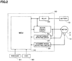
- the control unit (ECU) 30 basically has a basic configuration shown in FIG. 2 , and comprises the micro control unit (MCU) 31 equipped with a central processing unit (CPU), a motor driving circuit 35, a motor current detecting circuit 37, a steering angle detecting circuit 39, a relay 33 of a power supply and so on.
- MCU micro control unit
- CPU central processing unit
- motor driving circuit 35 motor driving circuit
- motor current detecting circuit 37 motor current detecting circuit 37
- a steering angle detecting circuit 39 a relay 33 of a power supply and so on.
- a program execution monitoring dedicated circuit 110 of the present embodiment is mounted within the MCU 31 of the control unit 30.
- FIG. 3 shows a schematic configuration of the MCU 31, the inside of MCU 31 comprises the program execution monitoring dedicated circuit 110 of the present embodiment, a CPU 130, a ROM (including an EEPROM, etc.) 150, a RAM 170, peripherals 190 including interfaces etc., and so on, and these are connected by data bus, command bus and so on.
- a control program of the electric power steering apparatus being comprised of a plurality of processes, control data, etc. are stored in the ROM 150, the CPU 130 performs the control of the electric power steering apparatus by executing the above control program, and the RAM 170 functions also as a work memory when the CPU 130 operates.
- a signal wire of interruption instruction to the CPU 130, a signal wire of a hardware (HW) alarm to an external port, etc. are connected from the program execution monitoring dedicated circuit 110.
- the program execution monitoring dedicated circuit 110 of the present embodiment comprises an execution sequence monitoring comparison circuit 113, an execution time monitoring timer circuit 111, a setting register 115 and an other attached circuit 117.
- the execution sequence monitoring comparison circuit 113 is a circuit that monitors whether a task (a processing) executed by the control program in the CPU 130 is performed in order or not, and is a circuit that monitors whether or not the processing is executed under a predetermined process, whether or not the most recent task is a proper task, and so on.
- execution time monitoring timer circuit 111 is a circuit that monitors whether each processing is executed after the elapse of a time more than or equal to a certain threshold predetermined for every processing or not.
- the setting register 115 is a register that preliminarily records setting information used in the operation of the program execution monitoring dedicated circuit 110.
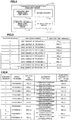
- FIG. 5 is a setting example of the setting register 115 of the program execution monitoring dedicated circuit 110 within the MCU 31 with respect to a certain process.
- the processes mean a plurality of control procedures that configure the control program, for example, include a torque control process for calculating a current command value based on a steering torque Th and a vehicle speed Vel, a current control process for driving a motor 20 based on the current command value, and so on.
- each process periodically executes a plurality of processings, and the number of the plurality of processings is different for every process.
- setting conditions such as the kind of the processing ordinarily performed by the program, an execution sequence thereof and an execution time threshold thereof, and the kind of the processing in the case that the program performs the alternative processing, the execution sequence thereof and the execution time threshold thereof are stored in the setting register 115.
- execution time threshold of the processing in the case of performing the alternative processing of FIG. 6 is set to half of the execution time threshold of the processing ordinarily performed
- contents of the alternative processing and the execution time threshold of the alternative processing are an example and are not limited to this example. Therefore, it is also possible to supplement a plurality of normal processings with one alternative processing in some cases, and it is also possible to set the execution time threshold of the one alternative processing so as not to be limited to half of the execution time threshold of the processing ordinarily performed.
- the other attached circuit 117 is provided with a hardware (HW) timer, a timer counter, a comparison register etc., and is further provided with a generating circuit of the interruption processing and the HW alarm, a log register for storing the execution sequence and the execution time read from the CPU 130, the presence or absence of alternative processing execution etc., and so on as necessary.
- HW hardware
- execution monitoring of the control program and necessary alternative processing are performed by the following execution procedure.
- the monitoring of execution sequence is performed by obtaining information about that which processing is currently executed based on processing addresses in command fetch and information about the program counter within the CPU etc., and comparing the obtained information with respective head addresses (processing addresses) of a plurality of processings (the processing 1 to the processing n) including a function pointer table etc. that are preliminarily registered in the setting register by means of the execution sequence monitoring comparison circuit 113 within the program execution monitoring dedicated circuit 110.
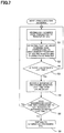
- Step S1 when the CPU 130 executes a task, command codes etc. are read out from the ROM 150 and transmitted to the register within the CPU 130. Therefore, as shown in FIG. 7 , the program execution monitoring dedicated circuit 110 reads out processing address of command code transmitted to the register of the CPU 130 and so on from the register within the CPU 130 or access information to the ROM 150 and so on (Step S1).
- Step S2 the processing address preliminarily registered in the setting register 115 within the program execution monitoring dedicated circuit 110 is compared with the processing address of command code and so on read out as above, and information about that processing having the same processing address exists in what number execution sequence (1 to n) among processing addresses registered in the setting register 115 is stored in the log register as log information (Step S2).
- Step S3 the presence or absence of record of execution sequence of processing until the last time is detected from the log information of the log register (Step S3), return to the Step S1 in the absence of the record of execution sequence of processing until the last time, and shift to the next Step S4 in the presence of the record of execution sequence of processing.
- next Step S4 information about that processing detected last time is what number execution sequence is fetched from the log information of the log register, and in the subsequent Step S5, it is judged whether or not execution sequence of processing detected this time corresponds to next execution sequence of processing detected last time.
- Step S5 shift to the next Step S6 that performs the generation of the HW alarm and the alternative processing and so on.
- the execution sequence monitoring comparison circuit 113 within the program execution monitoring dedicated circuit 110 of the present embodiment although the monitoring of execution sequence of the above control program is performed based on respective head addresses (processing addresses) of a plurality of processings (the processing 1 to the processing n), for example, in the program execution monitoring of the present embodiment, it is also possible to employ a configuration and a method that read execution sequence of each process from the program counter of the CPU 130, compare with the processing address preliminarily registered in the setting register within the program execution monitoring dedicated circuit 110, and monitor the validity of selection of process itself and so on.
- each process configuring the control program is subdivided for every processing, with respect to each processing (the processing 1 to the processing n), the execution time threshold for the execution time monitoring is set and stored in the setting register 115. Then, as shown in FIG. 6 , with respect to the above each processing, an alternative processing is set so as to pair up the alternative processing with the above each processing, further, with respect to the alternative processing, the execution time threshold is set and stored in the setting register 115 similarly.
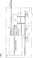
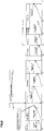
- FIG. 8 is a conceptual diagram showing a measurement example in the case that with respect to the above plurality of processings n (processing n: where 1 ⁇ n ⁇ N), the execution time of the processing does not exceed the predetermined execution time threshold, that is, in the case that abnormality does not occur in execution time of the processing by the CPU 130, and the operation of the execution time monitoring timer circuit 111 of the present embodiment matching that.
- FIG. 8 also shows a case of further shifting to the same processing in the next period in the case of setting the number of a plurality of processings of one process to "N".
- a vertical axis shows the execution time that has elapsed for every processing. Therefore, a rising hatched line from the bottom left to the top right indicated by a solid line for every processing represents the elapse of time for the every processing, and a chain line similarly indicated for every processing shows the execution time threshold set for every processing.
- the execution time monitoring timer circuit 111 when each processing n is started, at the same, the monitoring of the execution time by the execution time monitoring timer circuit 111 starts.
- the above monitoring of execution time is performed by means of a timer within the program execution monitoring dedicated circuit 110.
- the execution time monitoring timer circuit 111 the elapse of the execution time is measured, at the same, a comparison with the execution time threshold preliminarily set for that processing and described in FIGs. 5 and 6 is performed, and in the case that each processing is terminated before an elapsed time for the above each processing (the rising solid line from the bottom left to the top right in FIG. 8 ), that is, the execution time reaches the execution time threshold preliminarily set for each processing (the chain line of a horizontal direction shown in FIG. 8 ), the monitoring of the execution time by the execution time monitoring timer circuit 111 is stopped.
- N processings configuring one process are repeated in the same way, and then shift to the next process or the processing of the next period. Further, it is possible to automatically perform all of the above processings based on information preliminarily set by means of the program execution monitoring dedicated circuit 110.
- the setting information such as the execution time threshold for the above each processing and so on is preliminarily inputted into the setting register 115 or the like, read and used as necessary, and it is also possible that a synchronization between the hardware timer of the program execution monitoring dedicated circuit 110 and a clock of the CPU is preliminarily taken as necessary.
- FIG. 9 is a diagram configured in the same way as mentioned above, FIG. 9 differs from the case of FIG. 8 and is a conceptual diagram showing a measurement example in the case that abnormality occurs in execution time and the operation of the execution time monitoring timer circuit 111 of the present embodiment matching that.
- the execution time monitoring timer circuit 111 in the same way as mentioned above, the elapse of the execution time is measured, at the same, a comparison with the execution time threshold preliminarily set for that processing is performed, and whether an elapsed time for the above each processing (a rising solid line from the bottom left to the top right in FIG. 9 ), that is, the execution time reaches the execution time threshold preliminarily set for each processing (a chain line of a horizontal direction shown in FIG. 9 ) or not is monitored.
- an interruption is informed to the CPU 130 by means of the program execution monitoring dedicated circuit 110 as the occurrence of the abnormality in the execution time and then an interruption processing is performed.
- the above interruption processing is a processing that replaces the processing where it is determined that the above abnormality occurs with an alternative processing and executes the alternative processing. Therefore, for example, in the case of the processing 2 of FIG. 9 , as shown in FIG. 6 , when the processing execution time of the processing 2 reaches 120 [ ⁇ s] and it is judged that there is an abnormality in the execution time, the above processing 2 is properly stopped and the alternative processing for the processing 2 is perf ormedby the interruption.
- the interruption processing itself is a processing by software.
- processing N the flow of the processing in the execution time monitoring timer circuit 111 in the case that the execution time of the processing exceeds the predetermined execution time threshold, that is, in the case that the abnormality occurs will be described with reference to FIG. 10 .
- FIG. 10 is a flowchart showing a general outline of the flow of such an interruption processing.
- Step S20 an interruption inhibition processing is performed (Step S20). This is to prevent a matter that during the operation of the interruption based on an instruction by the program execution monitoring dedicated circuit 110, further, another interruption is instructed to the CPU 130 and a multi-interruption occurs.
- Step S21 a processing-being-executed search processing is performed.
- the Step S23 is a processing that rearranges contents such as command codes and function execution tables of the CPU 130 so as to replace the processing-being-executed with an alternative processing. Since the above alternative processing is preliminarily set for each processing as described in FIG. 6 , the rearrangement is performed based on the above setting.
- Step S24 is a step that performs reset of the setting register 115 or the like of the program execution monitoring dedicated circuit 110 to monitor the execution time and the sequence of alternative processing. Therefore, here, information such as processing address of the next processing of the processing-being-executed, and processing address and alternative processing's execution time threshold of the alternative processing are recorded in the setting register 115 or the like for later reference.
- Step S25 a processing N's calculation value check processing is performed. This is a matter that performs a judgment on whether the calculation value of the processing N where the alternative processing is performed, is abnormal or not (Step S26), and that judgment is performed by whether or not the calculation value of the processing N based on the alternative processing is within a predetermined threshold that is preliminarily set and so on. Then, in the case of judging that there is an abnormality in the above calculation value of the processing N, the calculation value of the processing N is replaced with a default value (Step S27), and in the case of judging that there is no abnormality in the above calculation value of the processing N, shift to the Step S28.
- the Step S28 sets the program counter of the CPU 130 to head of a processing "N+1", performs an instruction for permitting other interruptions inhibited by the Step S20 (Step S29), and terminates the interruption by the program execution monitoring dedicated circuit 110.
- the execution monitoring of the above program is performed by the program execution monitoring dedicated circuit mounted in the inside of the MCU, it is possible for the program execution monitoring dedicated circuit to know which processing is currently executed based on the information such as command fetch addresses from the command bus and the program counter within the CPU, and concurrently by this, when head addresses and upper limit thresholds of the execution time of the processing 1 to the processing N are preliminarily registered in the setting register, it is possible to almost automatically measure the execution time by means of the timer within the program execution monitoring dedicated circuit.
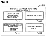
- the second embodiment has a change in an execution time monitoring timer circuit 211 configuring a program execution monitoring dedicated circuit 210. There is no change in other configurations, which are the same as for the first embodiment.
- the execution time monitoring timer circuit 211 performs the operation which the execution time monitoring timer circuit 111 in the first embodiment performs, and, in addition, can perform an operation that in the case that a processing of general-purpose interruption with high priority (a priority interruption) occurring asynchronously in measurement of an execution time of a task, such as an A/D conversion processing, a CAN communication processing, a timer clock processing, etc. occurs in the monitoring of the execution time, the execution time of these processings is not included in the execution time of the task.
- a processing of general-purpose interruption with high priority a priority interruption
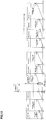
- FIG. 12 is a diagram configured in the same way as FIG. 8 , and is a conceptual diagram showing a measurement example in the case that the priority interruption as described above occurs in measurement of an execution time of a processing 3 and the operation of the execution time monitoring timer circuit 211 of the present embodiment matching that.
- FIG. 13 is a flowchart showing an example of the operation immediately after the priority interruption occurs. In the following, the operation in the processing 3 will be mainly described.
- the execution time monitoring timer circuit 211 like the case of FIG. 8 , the elapse of the execution time is measured, at the same, a comparison with the execution time threshold preliminarily set for that processing is performed. Then, when the priority interruption occurs in measurement of the execution time of the processing 3, a timer count value at that time is stored in a general-purpose register or the like provided for the other attached circuit 117 (Step S10), a timer stops (Step S11), and the monitoring of the execution time is stopped. In addition, when the timer stops, at the same time, the timer count value is cleared to zero.
- Step S12 When the processing of the priority interruption (Step S12) is terminated, the timer count value that has been stored in the general-purpose register or the like is preset as an initial value of the timer (Step S13), and the monitoring of the execution time is resumed (Step S14).
- an elapsed time for the processing 3 changes as shown by a rising solid line from the bottom left to the top right in FIG. 12 , in the case that the elapsed time, that is, the execution time terminates before reaching the execution time threshold preliminarily set for the processing 3 (the chain line of a horizontal direction shown in FIG. 12 ), the monitoring of the execution time by the execution time monitoring timer circuit 211 is stopped.
- the execution time of the priority interruption processing in the execution time of the task that is, whether or not to stop the monitoring of the execution time of the task during the priority interruption to be chosen.
- the frequency of occurrence of the priority interruption can be predicted to some extent, the task operates normally, but not stopping the measurement of the execution time enables abnormality that the priority interruption occurs at very higher frequency than expected to be detected.
- the measurement of the execution time is performed from a processing N to a processing N+1, however, there is also a case of wanting to measure an execution time of only a processing Nor an execution time of such discontinuous processings as a processing N and a processing N+2. In that case, it is also possible to add "an end address" in addition to the head address of the processing N to the setting register in the program execution monitoring dedicated circuit, and terminate the measurement when reaching "the end address".
- the setting register in order to measure the execution time within the interruption processing, it is also possible to configure the setting register to be divided according to the normal processing (periodic processing) and the interruption processing.
- control apparatus and the control method of on-vehicle electronic equipment of the present invention it is possible to monitor the abnormal execution state of the control program of the on-vehicle electronic equipment as described above and continuously perform the control by performing the alternative processing when the above abnormal execution state is detected.
- control apparatus and the control method of on-vehicle electronic equipment of the present invention are used in the control of the electric power steering apparatus, even in the case of judging that abnormality occurs in the control apparatus thereof, it is possible to continuously perform the steering assist.
Landscapes
- Engineering & Computer Science (AREA)
- Theoretical Computer Science (AREA)
- Mechanical Engineering (AREA)
- General Engineering & Computer Science (AREA)
- General Physics & Mathematics (AREA)
- Physics & Mathematics (AREA)
- Chemical & Material Sciences (AREA)
- Combustion & Propulsion (AREA)
- Transportation (AREA)
- Quality & Reliability (AREA)
- Software Systems (AREA)
- Power Steering Mechanism (AREA)
- Steering Control In Accordance With Driving Conditions (AREA)
- Debugging And Monitoring (AREA)
Applications Claiming Priority (3)
| Application Number | Priority Date | Filing Date | Title |
|---|---|---|---|
| PCT/JP2014/075396 WO2016046931A1 (ja) | 2014-09-25 | 2014-09-25 | 車載用電子機器の制御装置及び制御方法 |
| JP2015143876 | 2015-07-21 | ||
| PCT/JP2015/076626 WO2016047576A1 (ja) | 2014-09-25 | 2015-09-18 | 車載用電子機器の制御装置及び制御方法 |
Publications (2)
| Publication Number | Publication Date |
|---|---|
| EP3199408A1 true EP3199408A1 (de) | 2017-08-02 |
| EP3199408A4 EP3199408A4 (de) | 2018-09-26 |
Family
ID=55581103
Family Applications (1)
| Application Number | Title | Priority Date | Filing Date |
|---|---|---|---|
| EP15844897.7A Withdrawn EP3199408A4 (de) | 2014-09-25 | 2015-09-18 | Steuerungsvorrichtung und steuerungsverfahren für eine elektronische vorrichtung in einem fahrzeug |
Country Status (5)
| Country | Link |
|---|---|
| US (1) | US9889881B2 (de) |
| EP (1) | EP3199408A4 (de) |
| JP (3) | JP6164374B2 (de) |
| CN (1) | CN106794810B (de) |
| WO (1) | WO2016047576A1 (de) |
Cited By (1)
| Publication number | Priority date | Publication date | Assignee | Title |
|---|---|---|---|---|
| FR3101973A1 (fr) * | 2019-10-10 | 2021-04-16 | Continental Automotive | Dispositif de surveillance |
Families Citing this family (9)
| Publication number | Priority date | Publication date | Assignee | Title |
|---|---|---|---|---|
| CN106794809B (zh) * | 2014-09-25 | 2018-02-13 | 日本精工株式会社 | 车载用电子设备的控制装置以及控制方法 |
| JP6415405B2 (ja) * | 2015-07-31 | 2018-10-31 | 本田技研工業株式会社 | タスク制御システム |
| JP6428980B2 (ja) * | 2016-09-16 | 2018-11-28 | 日本精工株式会社 | 電動パワーステアリング装置 |
| US10831578B2 (en) | 2018-09-28 | 2020-11-10 | Nxp Usa, Inc. | Fault detection circuit with progress register and status register |
| CN114464008B (zh) * | 2019-03-07 | 2023-04-21 | 西安艾润物联网技术服务有限责任公司 | 车辆进出场所的警示方法及装置 |
| CN113127287B (zh) * | 2019-12-31 | 2024-05-10 | 北京车和家信息技术有限公司 | 处理器的控制方法、装置及电子设备 |
| CN111917620B (zh) * | 2020-08-19 | 2021-12-21 | 潍柴动力股份有限公司 | Mcu业务处理方法、装置、电子设备及可存储介质 |
| DE112020007796T5 (de) | 2020-11-24 | 2023-09-28 | Mitsubishi Electric Corporation | In-fahrzeug-verwendung-steuersystem |
| US11620221B2 (en) * | 2021-04-06 | 2023-04-04 | Nxp B.V. | Data flow monitoring in a multiple core system |
Family Cites Families (20)
| Publication number | Priority date | Publication date | Assignee | Title |
|---|---|---|---|---|
| GB1312504A (en) * | 1970-05-20 | 1973-04-04 | Ibm | Control unit for serial data storage apparatus |
| JPS5949430B2 (ja) * | 1975-10-30 | 1984-12-03 | 株式会社デンソー | テンカジキセツテイソウチ |
| JPH06324914A (ja) * | 1993-05-13 | 1994-11-25 | Fuji Electric Co Ltd | コンピュータの暴走検出方法 |
| US7028819B2 (en) * | 1996-02-21 | 2006-04-18 | Hitachi, Ltd. | Device and method for supplying power to a vehicle, semi-conductor circuit device for use in the same and collective wiring device for a vehicle or an automobile |
| JPH10198554A (ja) * | 1997-01-14 | 1998-07-31 | Hitachi Ltd | 制御装置 |
| JPH10198584A (ja) * | 1997-01-14 | 1998-07-31 | Nippon Steel Corp | アプリケーションソフトウェアの異常監視装置 |
| JP2000322277A (ja) * | 1999-05-12 | 2000-11-24 | Matsushita Electric Ind Co Ltd | タスク管理装置 |
| KR100345115B1 (ko) | 1999-12-14 | 2002-07-24 | 현대자동차주식회사 | 로직 진단 방법 |
| JP2001318807A (ja) * | 2000-05-11 | 2001-11-16 | Nec Microsystems Ltd | タスク切り替え制御方法及び装置 |
| JP4037617B2 (ja) * | 2001-03-16 | 2008-01-23 | 株式会社東芝 | 欠陥検索方法 |
| US6952795B2 (en) * | 2001-09-24 | 2005-10-04 | Motorola, Inc. | Method and apparatus for verifying the integrity of control module operation |
| JP2005107757A (ja) * | 2003-09-30 | 2005-04-21 | Matsushita Electric Ind Co Ltd | プログラムの暴走検出方法およびプログラムの暴走検出装置 |
| JP2006090356A (ja) | 2004-09-21 | 2006-04-06 | Denso Corp | 車両制御装置、および処理負荷制御プログラム。 |
| JP2009113618A (ja) | 2007-11-06 | 2009-05-28 | Nsk Ltd | 電動パワーステアリング装置 |
| JP4661854B2 (ja) * | 2007-11-09 | 2011-03-30 | 株式会社デンソー | 検査システム及びプログラム |
| JP5267186B2 (ja) * | 2009-02-13 | 2013-08-21 | 日本精工株式会社 | 電動パワーステアリング装置 |
| JP2011150532A (ja) * | 2010-01-21 | 2011-08-04 | Toyota Motor Corp | 情報処理装置 |
| JP2014026347A (ja) * | 2012-07-24 | 2014-02-06 | Auto Network Gijutsu Kenkyusho:Kk | 監視装置、コンピュータプログラム及び監視方法 |
| CN106794809B (zh) * | 2014-09-25 | 2018-02-13 | 日本精工株式会社 | 车载用电子设备的控制装置以及控制方法 |
| BR112016003514A2 (pt) * | 2014-09-25 | 2021-04-13 | Nks Ltd. | aparelho de controle e método de controle de equipamentos eletrônicos instalados em veículos |
-
2015
- 2015-09-18 JP JP2016550165A patent/JP6164374B2/ja not_active Expired - Fee Related
- 2015-09-18 WO PCT/JP2015/076626 patent/WO2016047576A1/ja not_active Ceased
- 2015-09-18 EP EP15844897.7A patent/EP3199408A4/de not_active Withdrawn
- 2015-09-18 US US15/312,275 patent/US9889881B2/en not_active Expired - Fee Related
- 2015-09-18 CN CN201580051307.7A patent/CN106794810B/zh not_active Expired - Fee Related
-
2017
- 2017-06-21 JP JP2017121194A patent/JP6311829B2/ja active Active
- 2017-06-21 JP JP2017121195A patent/JP6350724B2/ja not_active Expired - Fee Related
Cited By (1)
| Publication number | Priority date | Publication date | Assignee | Title |
|---|---|---|---|---|
| FR3101973A1 (fr) * | 2019-10-10 | 2021-04-16 | Continental Automotive | Dispositif de surveillance |
Also Published As
| Publication number | Publication date |
|---|---|
| JP6311829B2 (ja) | 2018-04-18 |
| JP6350724B2 (ja) | 2018-07-04 |
| WO2016047576A1 (ja) | 2016-03-31 |
| US20170190358A1 (en) | 2017-07-06 |
| CN106794810A (zh) | 2017-05-31 |
| JPWO2016047576A1 (ja) | 2017-04-27 |
| EP3199408A4 (de) | 2018-09-26 |
| JP2017174463A (ja) | 2017-09-28 |
| JP6164374B2 (ja) | 2017-07-26 |
| CN106794810B (zh) | 2018-03-20 |
| JP2017199403A (ja) | 2017-11-02 |
| US9889881B2 (en) | 2018-02-13 |
Similar Documents
| Publication | Publication Date | Title |
|---|---|---|
| EP3199407B1 (de) | Steuerungsvorrichtung und steuerungsverfahren für eine elektronische vorrichtung in einem fahrzeug | |
| EP3023304B1 (de) | Steuerungsvorrichtung und steuerungsverfahren für fahrzeugmontierte elektronische vorrichtung | |
| US9889881B2 (en) | Control apparatus and control method of on-vehicle electronic equipment | |
| JP2009113618A (ja) | 電動パワーステアリング装置 | |
| JP5267186B2 (ja) | 電動パワーステアリング装置 | |
| EP3173292B1 (de) | Steuerungsvorrichtung und steuerungsverfahren für fahrzeugmontierte elektronische vorrichtung | |
| JP6311693B2 (ja) | 車載用電子機器の制御装置及び制御方法 | |
| JP6481789B2 (ja) | 車載用電子機器の制御装置及び制御方法 | |
| JP6481788B2 (ja) | 車載用電子機器の制御装置及び制御方法 |
Legal Events
| Date | Code | Title | Description |
|---|---|---|---|
| PUAI | Public reference made under article 153(3) epc to a published international application that has entered the european phase |
Free format text: ORIGINAL CODE: 0009012 |
|
| 17P | Request for examination filed |
Effective date: 20170119 |
|
| AK | Designated contracting states |
Kind code of ref document: A1 Designated state(s): AL AT BE BG CH CY CZ DE DK EE ES FI FR GB GR HR HU IE IS IT LI LT LU LV MC MK MT NL NO PL PT RO RS SE SI SK SM TR |
|
| AX | Request for extension of the european patent |
Extension state: BA ME |
|
| DAV | Request for validation of the european patent (deleted) | ||
| DAX | Request for extension of the european patent (deleted) | ||
| A4 | Supplementary search report drawn up and despatched |
Effective date: 20180823 |
|
| RIC1 | Information provided on ipc code assigned before grant |
Ipc: B62D 5/04 20060101ALI20180817BHEP Ipc: G06F 11/28 20060101ALI20180817BHEP Ipc: G06F 9/48 20060101ALI20180817BHEP Ipc: G06F 11/07 20060101ALI20180817BHEP Ipc: B60R 16/02 20060101AFI20180817BHEP Ipc: B62D 6/00 20060101ALI20180817BHEP |
|
| 17Q | First examination report despatched |
Effective date: 20190506 |
|
| STAA | Information on the status of an ep patent application or granted ep patent |
Free format text: STATUS: THE APPLICATION HAS BEEN WITHDRAWN |
|
| 18W | Application withdrawn |
Effective date: 20200623 |