WO2013125409A1 - Ensemble moyeu pour véhicule et dispositif de réglage de pression d'air - Google Patents
Ensemble moyeu pour véhicule et dispositif de réglage de pression d'air Download PDFInfo
- Publication number
- WO2013125409A1 WO2013125409A1 PCT/JP2013/053389 JP2013053389W WO2013125409A1 WO 2013125409 A1 WO2013125409 A1 WO 2013125409A1 JP 2013053389 W JP2013053389 W JP 2013053389W WO 2013125409 A1 WO2013125409 A1 WO 2013125409A1
- Authority
- WO
- WIPO (PCT)
- Prior art keywords
- air
- wheel
- air passage
- opening
- adjusting device
- Prior art date
- Legal status (The legal status is an assumption and is not a legal conclusion. Google has not performed a legal analysis and makes no representation as to the accuracy of the status listed.)
- Ceased
Links
Images





Classifications
-
- B—PERFORMING OPERATIONS; TRANSPORTING
- B60—VEHICLES IN GENERAL
- B60B—VEHICLE WHEELS; CASTORS; AXLES FOR WHEELS OR CASTORS; INCREASING WHEEL ADHESION
- B60B1/00—Spoked wheels; Spokes thereof
- B60B1/06—Wheels with compression spokes
- B60B1/12—Wheels with compression spokes with tubular spokes
-
- B—PERFORMING OPERATIONS; TRANSPORTING
- B60—VEHICLES IN GENERAL
- B60B—VEHICLE WHEELS; CASTORS; AXLES FOR WHEELS OR CASTORS; INCREASING WHEEL ADHESION
- B60B19/00—Wheels not otherwise provided for or having characteristics specified in one of the subgroups of this group
-
- B—PERFORMING OPERATIONS; TRANSPORTING
- B60—VEHICLES IN GENERAL
- B60B—VEHICLE WHEELS; CASTORS; AXLES FOR WHEELS OR CASTORS; INCREASING WHEEL ADHESION
- B60B19/00—Wheels not otherwise provided for or having characteristics specified in one of the subgroups of this group
- B60B19/08—Wheels not otherwise provided for or having characteristics specified in one of the subgroups of this group with lubricating passages, channels, or reservoirs
-
- B—PERFORMING OPERATIONS; TRANSPORTING
- B60—VEHICLES IN GENERAL
- B60B—VEHICLE WHEELS; CASTORS; AXLES FOR WHEELS OR CASTORS; INCREASING WHEEL ADHESION
- B60B21/00—Rims
-
- B—PERFORMING OPERATIONS; TRANSPORTING
- B60—VEHICLES IN GENERAL
- B60B—VEHICLE WHEELS; CASTORS; AXLES FOR WHEELS OR CASTORS; INCREASING WHEEL ADHESION
- B60B27/00—Hubs
- B60B27/0047—Hubs characterised by functional integration of other elements
-
- B—PERFORMING OPERATIONS; TRANSPORTING
- B60—VEHICLES IN GENERAL
- B60B—VEHICLE WHEELS; CASTORS; AXLES FOR WHEELS OR CASTORS; INCREASING WHEEL ADHESION
- B60B3/00—Disc wheels, i.e. wheels with load-supporting disc body
-
- B—PERFORMING OPERATIONS; TRANSPORTING
- B60—VEHICLES IN GENERAL
- B60B—VEHICLE WHEELS; CASTORS; AXLES FOR WHEELS OR CASTORS; INCREASING WHEEL ADHESION
- B60B3/00—Disc wheels, i.e. wheels with load-supporting disc body
- B60B3/02—Disc wheels, i.e. wheels with load-supporting disc body with a single disc body integral with rim
-
- B—PERFORMING OPERATIONS; TRANSPORTING
- B60—VEHICLES IN GENERAL
- B60B—VEHICLE WHEELS; CASTORS; AXLES FOR WHEELS OR CASTORS; INCREASING WHEEL ADHESION
- B60B3/00—Disc wheels, i.e. wheels with load-supporting disc body
- B60B3/10—Disc wheels, i.e. wheels with load-supporting disc body apertured to simulate spoked wheels
-
- B—PERFORMING OPERATIONS; TRANSPORTING
- B60—VEHICLES IN GENERAL
- B60C—VEHICLE TYRES; TYRE INFLATION; TYRE CHANGING; CONNECTING VALVES TO INFLATABLE ELASTIC BODIES IN GENERAL; DEVICES OR ARRANGEMENTS RELATED TO TYRES
- B60C23/00—Devices for measuring, signalling, controlling, or distributing tyre pressure or temperature, specially adapted for mounting on vehicles; Arrangement of tyre inflating devices on vehicles, e.g. of pumps or of tanks; Tyre cooling arrangements
- B60C23/001—Devices for manually or automatically controlling or distributing tyre pressure whilst the vehicle is moving
- B60C23/003—Devices for manually or automatically controlling or distributing tyre pressure whilst the vehicle is moving comprising rotational joints between vehicle-mounted pressure sources and the tyres
- B60C23/00309—Devices for manually or automatically controlling or distributing tyre pressure whilst the vehicle is moving comprising rotational joints between vehicle-mounted pressure sources and the tyres characterised by the location of the components, e.g. valves, sealings, conduits or sensors
- B60C23/00318—Devices for manually or automatically controlling or distributing tyre pressure whilst the vehicle is moving comprising rotational joints between vehicle-mounted pressure sources and the tyres characterised by the location of the components, e.g. valves, sealings, conduits or sensors on the wheels or the hubs
-
- B—PERFORMING OPERATIONS; TRANSPORTING
- B60—VEHICLES IN GENERAL
- B60C—VEHICLE TYRES; TYRE INFLATION; TYRE CHANGING; CONNECTING VALVES TO INFLATABLE ELASTIC BODIES IN GENERAL; DEVICES OR ARRANGEMENTS RELATED TO TYRES
- B60C23/00—Devices for measuring, signalling, controlling, or distributing tyre pressure or temperature, specially adapted for mounting on vehicles; Arrangement of tyre inflating devices on vehicles, e.g. of pumps or of tanks; Tyre cooling arrangements
- B60C23/001—Devices for manually or automatically controlling or distributing tyre pressure whilst the vehicle is moving
- B60C23/003—Devices for manually or automatically controlling or distributing tyre pressure whilst the vehicle is moving comprising rotational joints between vehicle-mounted pressure sources and the tyres
- B60C23/00345—Details of the rotational joints
- B60C23/00347—Details of the rotational joints comprising two or more feedthrough
-
- B—PERFORMING OPERATIONS; TRANSPORTING
- B60—VEHICLES IN GENERAL
- B60C—VEHICLE TYRES; TYRE INFLATION; TYRE CHANGING; CONNECTING VALVES TO INFLATABLE ELASTIC BODIES IN GENERAL; DEVICES OR ARRANGEMENTS RELATED TO TYRES
- B60C23/00—Devices for measuring, signalling, controlling, or distributing tyre pressure or temperature, specially adapted for mounting on vehicles; Arrangement of tyre inflating devices on vehicles, e.g. of pumps or of tanks; Tyre cooling arrangements
- B60C23/001—Devices for manually or automatically controlling or distributing tyre pressure whilst the vehicle is moving
- B60C23/003—Devices for manually or automatically controlling or distributing tyre pressure whilst the vehicle is moving comprising rotational joints between vehicle-mounted pressure sources and the tyres
- B60C23/00354—Details of valves
-
- B—PERFORMING OPERATIONS; TRANSPORTING
- B60—VEHICLES IN GENERAL
- B60C—VEHICLE TYRES; TYRE INFLATION; TYRE CHANGING; CONNECTING VALVES TO INFLATABLE ELASTIC BODIES IN GENERAL; DEVICES OR ARRANGEMENTS RELATED TO TYRES
- B60C23/00—Devices for measuring, signalling, controlling, or distributing tyre pressure or temperature, specially adapted for mounting on vehicles; Arrangement of tyre inflating devices on vehicles, e.g. of pumps or of tanks; Tyre cooling arrangements
- B60C23/001—Devices for manually or automatically controlling or distributing tyre pressure whilst the vehicle is moving
- B60C23/003—Devices for manually or automatically controlling or distributing tyre pressure whilst the vehicle is moving comprising rotational joints between vehicle-mounted pressure sources and the tyres
- B60C23/00372—Devices for manually or automatically controlling or distributing tyre pressure whilst the vehicle is moving comprising rotational joints between vehicle-mounted pressure sources and the tyres characterised by fluid diagrams
-
- B—PERFORMING OPERATIONS; TRANSPORTING
- B60—VEHICLES IN GENERAL
- B60C—VEHICLE TYRES; TYRE INFLATION; TYRE CHANGING; CONNECTING VALVES TO INFLATABLE ELASTIC BODIES IN GENERAL; DEVICES OR ARRANGEMENTS RELATED TO TYRES
- B60C23/00—Devices for measuring, signalling, controlling, or distributing tyre pressure or temperature, specially adapted for mounting on vehicles; Arrangement of tyre inflating devices on vehicles, e.g. of pumps or of tanks; Tyre cooling arrangements
- B60C23/02—Signalling devices actuated by tyre pressure
- B60C23/04—Signalling devices actuated by tyre pressure mounted on the wheel or tyre
-
- B—PERFORMING OPERATIONS; TRANSPORTING
- B60—VEHICLES IN GENERAL
- B60C—VEHICLE TYRES; TYRE INFLATION; TYRE CHANGING; CONNECTING VALVES TO INFLATABLE ELASTIC BODIES IN GENERAL; DEVICES OR ARRANGEMENTS RELATED TO TYRES
- B60C23/00—Devices for measuring, signalling, controlling, or distributing tyre pressure or temperature, specially adapted for mounting on vehicles; Arrangement of tyre inflating devices on vehicles, e.g. of pumps or of tanks; Tyre cooling arrangements
- B60C23/18—Tyre cooling arrangements, e.g. heat shields
-
- B—PERFORMING OPERATIONS; TRANSPORTING
- B60—VEHICLES IN GENERAL
- B60B—VEHICLE WHEELS; CASTORS; AXLES FOR WHEELS OR CASTORS; INCREASING WHEEL ADHESION
- B60B27/00—Hubs
-
- B—PERFORMING OPERATIONS; TRANSPORTING
- B60—VEHICLES IN GENERAL
- B60B—VEHICLE WHEELS; CASTORS; AXLES FOR WHEELS OR CASTORS; INCREASING WHEEL ADHESION
- B60B27/00—Hubs
- B60B27/0005—Hubs with ball bearings
-
- B—PERFORMING OPERATIONS; TRANSPORTING
- B60—VEHICLES IN GENERAL
- B60B—VEHICLE WHEELS; CASTORS; AXLES FOR WHEELS OR CASTORS; INCREASING WHEEL ADHESION
- B60B2900/00—Purpose of invention
- B60B2900/30—Increase in
- B60B2900/325—Reliability
-
- B—PERFORMING OPERATIONS; TRANSPORTING
- B60—VEHICLES IN GENERAL
- B60B—VEHICLE WHEELS; CASTORS; AXLES FOR WHEELS OR CASTORS; INCREASING WHEEL ADHESION
- B60B2900/00—Purpose of invention
- B60B2900/30—Increase in
- B60B2900/351—Increase in versatility, e.g. usable for different purposes or different arrangements
-
- B—PERFORMING OPERATIONS; TRANSPORTING
- B60—VEHICLES IN GENERAL
- B60B—VEHICLE WHEELS; CASTORS; AXLES FOR WHEELS OR CASTORS; INCREASING WHEEL ADHESION
- B60B2900/00—Purpose of invention
- B60B2900/50—Improvement of
- B60B2900/551—Handling of obstacles or difficult terrains
-
- B—PERFORMING OPERATIONS; TRANSPORTING
- B60—VEHICLES IN GENERAL
- B60B—VEHICLE WHEELS; CASTORS; AXLES FOR WHEELS OR CASTORS; INCREASING WHEEL ADHESION
- B60B3/00—Disc wheels, i.e. wheels with load-supporting disc body
- B60B3/06—Disc wheels, i.e. wheels with load-supporting disc body formed by casting
Definitions
- the present invention relates to a vehicle hub unit having a mechanism for changing the air pressure of a pneumatic tire and an air pressure adjusting device.
- the air pressure adjusting device is a device that adjusts the air pressure of the pneumatic tire mounted on the vehicle.
- the air pressure adjusting device adjusts the air pressure of the pneumatic tire based on the target air pressure calculated based on the vehicle traveling conditions (for example, vehicle speed, traveling road, road surface condition, etc.) while the vehicle is traveling. Thereby, the running performance and fuel consumption of the vehicle are improved.
- an air pressure adjusting device there is an air pressure adjusting system including an air pressure supplying device described in Patent Document 1.
- the air pressure adjusting system described in Patent Literature 1 includes a mechanism for supplying air to a pneumatic tire, and has an air passage for introducing compressed air into the pneumatic tire inside the hub unit and the wheel. .
- An object of the present invention is to provide a vehicle hub unit and an air pressure adjusting device capable of adjusting the air pressure of a pneumatic tire with higher responsiveness.
- the present invention provides a vehicle hub unit that supports a wheel connected to a pneumatic tire and is connected to a joint, wherein a first opening is provided at at least one position of a surface connected to the wheel.
- a first air passage formed and connected to an air pipe for supplying the joint air, supplying air to the wheel from the first opening, and a second opening at least on one of the surfaces connected to the wheel.
- a second air passage connected to an air pipe for discharging the joint air and collecting the air of the wheel from the second opening.
- an open valve that is disposed in the second air passage and discharges the air in the second air passage to the outside.
- an open valve that is disposed in the first air passage and discharges the air in the first air passage to the outside.
- an air pressure adjusting device of the present invention includes the vehicle hub unit according to any one of the above, and a wheel that is connected to the vehicle hub unit and supports a pneumatic tire.
- the wheel includes a hub mounting portion that is connected to the vehicle hub unit, a rim portion that supports the pneumatic tire, an opening that is connected to the first opening, and an opening that is formed on an outer peripheral surface of the rim portion. And a second wheel air passage connecting the opening connected to the second opening and the opening formed on the outer peripheral surface of the rim portion.
- the wheel has at least two spokes for connecting the hub mounting portion and the rim portion, the first wheel air passage is formed inside the spoke, and the second wheel air passage is It is preferable that it is formed inside the spoke.
- the first wheel air passage is formed inside the spoke different from the spoke in which the second wheel air passage is formed.
- the wheel includes a disk that connects the hub mounting part and the rim part, the first wheel air passage is formed inside the disk, and the second wheel air passage is formed on the disk. It is preferably formed inside.
- the wheel opens the first wheel air passage when the vehicle hub unit is attached to the hub mounting portion of the first wheel air passage, and the wheel releases the first wheel air passage when detached from the vehicle hub unit.
- An air connection valve for closing the one-wheel air passage, the second wheel air passage is opened when the vehicle hub unit is attached to the hub mounting portion of the second wheel air passage, and the vehicle hub unit It is preferable to provide an air connection valve that closes the second wheel air passage when leaving the vehicle.
- the wheel has two or more types of cross-sectional shapes of the opening on the rim portion side of the first wheel air passage and the second wheel air passage.
- the wheel has a cross-sectional area S of 100 [mm 2 ] ⁇ S ⁇ 3000 [mm 2 ], where S is a cross-sectional area of the first wheel air passage and the second wheel air passage. It is preferable that
- the radial width A is 35 [mm] ⁇ A ⁇ 100 [mm], where A is the radial width of the mounting surface of the hub mounting portion.
- the vehicular hub unit has a joint connected to the surface on which the first opening and the second opening are formed, and the joint is connected to each of the first opening and the second opening.
- the joint is a rotary joint with a passage.
- the vehicle hub unit is connected to the first opening and the second opening, supplies air to the first opening, discharges air from the second opening, and enters the air mounted on the wheel.
- a pressure increasing / decreasing unit that pressurizes and depressurizes the tire air pressure; a pressure sensor that detects the air pressure of the pneumatic tire; and a control unit that drives and controls the pressure increasing / decreasing unit based on an output signal of the pressure sensor. It is preferable to provide.
- the supply of air to the pneumatic tire and the discharge of air from the pneumatic tire can be realized with high responsiveness, and the pneumatic pressure of the pneumatic tire can be adjusted with higher responsiveness. There is an effect that can be done.
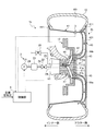
- FIG. 1 is a configuration diagram showing a schematic configuration of an air pressure adjusting device according to an embodiment of the present invention.
- FIG. 2 is an explanatory view showing the wheel shown in FIG.
- FIG. 3 is an explanatory view showing another example of a wheel.
- FIG. 4 is an explanatory view showing the wheel shown in FIG.
- FIG. 5 is a configuration diagram illustrating a schematic configuration of an air pressure adjusting device according to another embodiment.
- FIG. 6 is a configuration diagram showing a schematic configuration of an air pressure adjusting device according to another embodiment.
- FIG. 7 is an explanatory view showing the wheel shown in FIG.
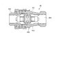
- FIG. 8 is an axial sectional view showing the air connection valve of the wheel shown in FIG. 6.
- FIG. 9 is a configuration diagram showing a schematic configuration of an air pressure adjusting device according to another embodiment.
- FIG. 1 is a configuration diagram showing a schematic configuration of an air pressure adjusting device according to an embodiment of the present invention.
- FIG. 1 shows an air pressure adjusting device 1 mounted on a vehicle (not shown).
- the air pressure adjusting device 1 is a device that adjusts the air pressure of the air chamber 101 of the pneumatic tire 10.
- the pressure adjusting unit 2, the pressure sensor 3, the wheel 4, the control unit 5, A hub unit 11 and a joint 13 are provided.
- the case where the air pressure adjusting device 1 adjusts the air pressure of the pneumatic tire 10 mounted on the vehicle will be described.
- a system that rotates together with the hub unit 11 of the vehicle, the wheel 4 and the pneumatic tire 10 when the vehicle travels is called a rotating system, and a system on the vehicle body (not shown) side is called a stationary system.
- the hub unit 11 and the wheel 4 connected to the pneumatic tire 10 also have functions as a vehicle hub unit and a wheel.
- a pneumatic tire 10 is mounted on the wheel 4.
- the wheel 4 is supported by the hub unit 11.
- a brake rotor 12 is connected to the hub unit 11.
- the hub unit 11 is connected to a joint 13. Further, the hub unit 11 is supported by the vehicle body via the support mechanism 14.
- the joint 13 is disposed on the same rotation axis as the hub unit 11.
- the joint 13 is in contact with the surface of the hub unit 11 opposite to the surface in contact with the wheel 4.
- the joint 13 is a shaft joint such as a rotary joint or a rotary seal, and even when the hub unit 11 is rotating, the joint 13 is connected to air passages 111 and 112 (described later) formed in the hub unit 11. Two air passages that can be maintained are formed.
- the support mechanism 14 is a stationary system.
- the support mechanism 14 is a suspension or the like, and reduces vibrations transmitted during traveling between the pneumatic tire 10 and the hub unit 11 and the vehicle body.
- the hub unit 11 has an inner hub 11a disposed at the center of rotation and an outer hub 11b disposed on the outer periphery of the inner hub 11a.
- the inner hub 11a and the outer hub 11b may be integrated.
- the outer hub 11b is supported by the support mechanism 14 in a rotatable state via a bearing or the like.
- the hub unit 11 has two air passages, an air passage 111 and an air passage 112.
- the air passage 111 is a passage formed across the inner hub 11a and the outer hub 11b, one end of which is connected to the air passage of the joint 13, and the other end is air to be described later of the wheel 4. It is connected with the passage 44a.
- the air passage 112 is a passage formed across the inner hub 11a and the outer hub 11b, one end of which is connected to the air passage of the joint 13, and the other end is air to be described later of the wheel 4. It is connected with the passage 44b.
- the air passages 111 and 112 of the present embodiment have a plurality of passages on the wheel 4 side, which are connected to the air passages 44a and 44b, respectively, and the passages on the joint 13 side are integrated into one. Note that the air passages 111 and 112 and the air pipes 24 and 25 of the present embodiment may be provided in a number corresponding to the number of the air passages 44a and 44b.
- the pressurizing / depressurizing unit 2 is a device that pressurizes and depressurizes the air filled in the pneumatic tire 10.
- the pressure increasing / decreasing unit 2 includes a pressurizing pump 21, a valve device 22, an air tank 23, an air pipe 24, an air pipe 25, and a valve device 26.
- the pressure increasing / decreasing unit 2 is installed in a stationary system.
- the pressurizing pump 21 is a pump that introduces outside air to generate compressed air, and is connected to the air pipe 24.
- the valve device 22 is installed in the air pipe 24.
- the valve device 22 is a valve that opens and closes the air pipe 24.
- the air tank 23 is disposed between the pressurizing pump 21 and the valve device 22 in the air pipe 24.
- the air tank 23 is a tank that stores compressed air.
- the air tank 23 is supplied with air from the pressurizing pump 21 to increase the amount of stored air, and the internal pressure is increased.
- the air tank 23 supplies air from the air pipe 24 to the air passage 111 or collects air inside the air passage 111.
- the air pipe 24 is connected to the air chamber 101 of the pneumatic tire 10 through the air passage of the joint 13, the air passage 111 of the hub unit 11, and the air passage 44 a of the wheel 4.
- the air passage 44a of the wheel 4 will be described later.
- the air pipe 25 is connected to the air chamber 101 of the pneumatic tire 10 through the air passage of the joint 13, the air passage 112 of the hub unit 11, and the air passage 44 b of the wheel 4.
- the air passage 44b of the wheel 4 will be described later.
- the valve device 26 is a valve that opens and closes the air pipe 25.
- the pressurizing and depressurizing unit 2 installs a part of the air pipe 24 and the air pipe 25 in the rotating system of the vehicle, the pressurizing pump 21, the valve device 22, the valve device 26, a part of the air pipe 24, A part of the pipe 25 may be installed in a stationary system.
- the boundary between the rotating part and the stationary part of the air pipe 24 and the air pipe 25 may be connected via a rotary joint like the joint 13 and the hub unit 11 described above. You may connect via a joint.
- the air piping 24 and 25 can maintain the connected state at the time of rotation of a rotating system.
- the pressurizing / depressurizing unit 2 is not limited to this embodiment, and all the mechanisms may be arranged in the rotating system, or the valve device 22 and the valve device 26 may be arranged in the rotating system.
- the air pressure adjusting device 1 and the vehicle serve as a mechanism for rotating the joint 13 when a part of the air pipe 24 and the air pipe 25 of the pressure increasing / decreasing unit 2 is disposed in the rotating system. Further, the air pressure adjusting device 1 and the vehicle may be configured such that the joint 13 is not provided when a part of the air pipe 24 and the air pipe 25 of the pressure increasing / decreasing unit 2 is arranged in the rotating system. Further, the air pipe 24 and the air pipe 25 may have an air passage formed in the joint 13 as a part of each air pipe.
- the vehicle when the corresponding wheel is a drive wheel, the vehicle may be configured to rotate integrally with the hub unit 11 using the joint 13 as a drive shaft.
- the joint 13 is connected to another joint, the connecting portion is connected by a rotary joint or the like, and the air pipe is connected.
- the pressure sensor 3 is a sensor that detects the air pressure of the air chamber 101 of the pneumatic tire 10, and is installed on the wheel 4 and rotates together with the wheel 4.
- the pressure sensor 3 only needs to be able to detect the air pressure in the air chamber 101, and the arrangement position is not limited to this.
- the pressure sensor 3 may be provided in a pipe connected to the air chamber 101, for example, in the air passages 44a, 44b, 111, 112, the air pipes 24, 25, and the like. That is, the air pressure adjusting device 1 only needs to be able to detect the pressure of the air chamber 101 (the pressure at which the pressure of the air chamber 101 can be calculated), and the pressure sensor 3 may be disposed in a stationary system.
- the wheel 4 is a vehicle wheel that is installed in a vehicle with the pneumatic tire 10 attached thereto, and is bolted and fixed to a hub unit 11 of the vehicle.
- FIG. 2 is an explanatory view showing the wheel shown in FIG.
- FIG. 3 is an explanatory view showing another example of a wheel.
- FIG. 4 is an explanatory view showing the wheel shown in FIG. FIG. 2 is a plan view of the inner side of the wheel 4.
- FIG. 3 is a modified example in which the configuration of a part of the wheel is changed.
- the wheel 4 includes a rim portion 41, a hub mounting portion 42, and a connecting portion 43 (see FIG. 2).
- the wheel 4 is made of, for example, cast aluminum, forged aluminum, resin, a composite of resin and aluminum, or the like.
- a resin when used, it is preferably made of a resin containing reinforcing short fibers, and the resin is more preferably made of a thermosetting resin.
- the rim portion 41 has an annular structure and has flanges 411 on the left and right edges (see FIG. 4).
- the pneumatic tire 10 is fitted to the flange 411 and attached to the wheel 4 (see FIG. 1).
- an air chamber 101 is formed between the outer peripheral surface of the rim portion 41 and the inner peripheral surface of the pneumatic tire 10.
- the hub mounting portion 42 has an annular structure and constitutes the rotating shaft of the wheel 4 (see FIG. 2).
- the wheel 4 is attached to the hub unit 11 of the vehicle with the end surface on the inner side of the hub attachment portion 42 as an attachment surface (see FIG. 1).
- the hub attachment portion 42 has a plurality of bolt holes 421 and is attached to the hub unit 11 of the vehicle via bolts inserted into these bolt holes 421.
- the connecting portion 43 is a portion that connects the rim portion 41 and the hub mounting portion 42, and includes, for example, a plurality of spokes 431 (see FIG. 2) or a single disk (not shown).
- the connection part 43 consists of a plurality of spokes 431, it is preferable that four or more spokes 431 are arranged.
- the wheel 4 is a spoke wheel, and the connecting portion 43 has six spokes 431 extending radially.
- the wheel 4 has air passages 44a and 44b that pass through the connecting portion 43 and open to the outer peripheral surface of the rim portion 41 and the mounting surface of the hub mounting portion 42, respectively (see FIG. 2).
- These air passages 44a and 44b constitute a part of an air passage that connects the pressure increasing / decreasing portion 2 of the air pressure adjusting device 1 and the air chamber 101 of the pneumatic tire 10 (see FIG. 1).
- the air passage 44a serves as an air introduction path from the pressurizing and depressurizing unit 2 to the air chamber 101 (when the air pressure of the pneumatic tire 10 is increased).
- the air passage 44b serves as an air discharge path from the air chamber 101 to the outside (when the air pressure of the pneumatic tire 10 is reduced).
- the connecting portion 43 includes a plurality of spokes 431 (see FIG. 2) as in the present embodiment, it is preferable to form the air passages 44a and 44b inside the spoke 431.
- the air passage 44 By providing the air passage 44 inside the plurality of spokes 431, a necessary flow passage cross-sectional area can be appropriately ensured.
- air passages 44a and 44b may be formed inside the disk.
- the connecting portion 43 of the wheel 4 is composed of six spokes 431, and these spokes 431 have air passages 44a and 44b that are independent of each other (see FIG. 2).
- each spoke 431 has a hollow structure, and thus has air passages 44a and 44b therein.
- the six spokes 431 alternately have air passages 44a and air passages 44b. That is, the wheel 4 is formed with three air passages 44a and three air passages 44b.
- Each air passage 44a, 44b opens to the base of the flange 411 on the outer side of the rim portion 41 in the outer peripheral surface of the rim portion 41 (see FIG. 2).
- each air passage 44 a and 44 b are arranged with the edge of the opening along the outer peripheral surface of the rim 41 while the direction of the opening is directed from the outer side to the inner side of the rim 41.
- each air passage 44 a is configured such that air introduced into the air chamber 101 from each air passage 44 a flows along the outer peripheral surface of the rim portion 41.
- air passages 44a and 44b of the spokes 431 are opened on the attachment surface of the hub attachment portion 42 (see FIG. 2).
- a bolt hole 421 for bolting the hub mounting portion 42 to the hub unit 11 of the vehicle is formed.
- the number of openings of the air passage 44 and the number of bolt holes 421 are the same.
- the openings of these air passages 44 and the bolt holes 421 are arranged alternately and at equal intervals around the rotation axis of the hub mounting portion 42.
- the wheel 4 shown in FIG. 2 arrange
- six spokes 431 may be provided and bolt holes 421 may be provided at five locations.
- the air passages 44 a and 44 b formed inside the spoke 431 may be provided with an opening connected to the hub unit 11 at a position deviated from the bolt hole 421.
- the wheels 4 and 4a arrange
- the wheels 4 and 4a preferably have the air passages 44a and the air passages 44b alternately arranged, and the air passage 44a and the air passage 44b are arranged symmetrically around the axis of symmetry passing through the rotation axis. Is preferred. Thereby, the supply of air to the air chamber 101 and the discharge of air from the air chamber 101 can be performed efficiently.
- the control unit 5 includes a signal relating to the target air pressure of the pneumatic tire 10 (for example, a signal from a vehicle ECU (Electronic Control Unit) or a dedicated air pressure control device mounted on the vehicle), a signal from the pressure sensor 3, This is a unit for driving and controlling the pressurizing pump 21, the valve device 22 and the valve device 26 of the pressurizing and depressurizing unit 2.
- the control unit 5 includes, for example, a CPU (Central Processing Unit), a RAM (Random Access Memory), a ROM (Read Only Memory), and the like.
- the control unit 5 is installed in a stationary system of the vehicle, and is electrically connected to the pressurizing pump 21, the valve device 22, the valve device 26, and the pressure sensor 3 in the rotating system. As a result, a signal transmission path between the control unit 5 and the pressurizing pump 21, the valve device 22, the valve device 26, and the pressure sensor 3 is secured, and the pressurizing pump 21 from a battery (not shown) in the vehicle body is secured. The power supply path to the valve device 22, the valve device 26, and the pressure sensor 3 is secured.
- the control unit 5 is connected to the pressurizing pump 21 and the valve devices 22 and 26 through various wirings and connection terminals.
- the control unit 5 is electrically connected to the pressure sensor 3 in the rotating system through a terminal, a plurality of sets of stationary terminals, rotating terminals, and the like.
- the terminal and each stationary terminal are installed in the stationary system of the vehicle.
- Each stationary terminal is formed of an annular conductor, and is arranged and supported on the terminal.
- the rotation terminal of the pressure sensor 3 is installed in the rotation system of the vehicle.
- each stationary terminal and each rotating terminal are slidably connected to each other via a slip ring structure. This ensures electrical connection between the control unit 5 in the stationary system and the pressure sensor 3 in the rotating system when the vehicle is traveling.
- the control unit 5 is electrically connected to each other through a terminal, a plurality of sets of stationary terminals and rotating terminals, as in the pressure sensor 3. Connecting.
- a vehicle ECU Electronic Control Unit
- a dedicated air pressure control device mounted on the vehicle controls a signal applied to the target air pressure of the pneumatic tire 10 while the vehicle is running. Input to part 5.
- This target air pressure is appropriately set according to the vehicle running conditions (for example, vehicle speed, travel path, road surface condition, etc.).
- the control unit 5 drives and controls the pressurization pump 21, the valve device 22, and the valve device 26 of the pressure increasing / decreasing unit 2 based on the signal concerning the target air pressure and the signal from the pressure sensor 3.
- the air pressure of the pneumatic tire 10 is adjusted, and the running performance and fuel consumption of the vehicle are improved.
- the control unit 5 drives the pressurizing pump 21. Then, the pressurizing pump 21 generates compressed air, and the compressed air is stored in the air tank 23. Note that the air pressure adjusting device 1 may be in a state in which the pressurized pump 21 is driven in advance and the compressed air is stored in the air tank 23. The air pressure adjusting device 1 opens the valve device 22 by the control unit 5 in a state where compressed air is stored in the air tank 23.
- the air pressure adjusting device 1 opens the valve device 22, the compressed air in the air tank 23 is supplied to the air chamber 101 of the pneumatic tire 10 via the air pipe 24, the air passage 111 of the hub unit 11, and the air passage 44 a of the wheel 4. Is done.
- the control unit 5 closes the valve device 22.
- the air pressure adjusting device 1 stops the pressurizing pump 21.
- the control unit 5 opens the valve device 26. Then, the air in the air chamber 101 is discharged through the air passage 44 b of the wheel 4, the air passage 112 of the hub unit 11, and the air pipe 25. When the actual air pressure in the air chamber 101 becomes the target air pressure, the control unit 5 closes the valve device 26. In this way, the air pressure adjusting device 1 controls the supply of air to the air chamber 101 of the pneumatic tire 10 and the discharge of air from the air chamber 101 of the pneumatic tire 10 by the pressure increasing / decreasing unit 2. The increase or decrease of air pressure can be adjusted.
- the air pressure adjusting device 1 may include a plurality of sets of units including the above-described pressurization / decompression unit 2, pressure sensor 3, wheel 4, hub unit 11, and joint 13.
- units each including a pressure-increasing / decreasing unit 2, a pressure sensor 3, a wheel 4, a hub unit 11, and a joint 13 are installed on each wheel.
- one control unit 5 installed in the vehicle body controls driving of each pressure increasing / decreasing unit 2 based on a signal from each pressure sensor 3.
- the air pressure of the pneumatic tire 10 attached to each wheel can be controlled simultaneously and independently.
- the air pressure adjusting device 1 includes the control unit 5, the pressure pump 21, and the air tank 23 as one common, and other mechanisms, valve devices 22 and 26, air pipes 24 and 25, etc. May be provided as a combination of each wheel 4 and pneumatic tire 10.
- a part of the air pipes 24 and 25, that is, a pipe connected to the pressurizing pump 21 and the air tank 23 may be shared.
- the air pressure adjusting device 1 is configured as described above.
- the air pressure adjusting unit 2 enters the air chamber 101 of the pneumatic tire 10 through the air passages 44a and 44b of the wheel 4, the air passages 111 and 112 of the hub unit 11, and the like.
- the air pressure of the pneumatic tire 10 can be adjusted with high responsiveness by supplying air or exhausting air from the air chamber 101.
- the air pressure adjusting device 1 can reduce the air pressure of the pneumatic tire 10 according to the running state by allowing the air pressure of the pneumatic tire 10 to be decreased in addition to increasing the air pressure.
- the wheel 4 of the air pressure adjusting device 1 is formed by connecting a rim portion 41 and a hub mounting portion 42 via a connecting portion 43 (see FIG. 2).
- the wheel 4 is fitted with the pneumatic tire 10 on the rim portion 41, and is attached to the hub unit 11 of the vehicle at the hub attachment portion 42 (see FIG. 1).
- the wheel 4 includes air passages 44 that pass through the connecting portion 43 and open to the outer peripheral surface of the rim portion 41 and the mounting surface of the hub mounting portion 42.
- the air passage 44a of the wheel 4 serves as an air introduction path from the outside (the pressure increasing / decreasing portion 2 of the air pressure adjusting device 1) to the air chamber 101, and the air
- the air passage 44b of the wheel 4 serves as an air discharge path from the air chamber 101 to the outside (see FIG. 1).
- the air passages 44a and 44b that can be circulated in both directions are formed inside the connecting portion 43, so that the configuration of the wheel 4 is compared with the configuration in which the piping for the air passage is arranged outside the wheel. There is an advantage that can be simplified.
- the wheel 4a includes a plurality of air passages 44a and 44b that are independent of each other (see FIG. 3). As a result, even when any one of the air passages 44a and 44b is disconnected, air can be circulated through the other air passages 44a and 44b, so that there is an advantage that a fail-safe function can be realized.
- the air pressure adjusting device 1 supplies air by a combination of the air passage 44 a, the air passage 111, and the air pipe 24 in the air passage 44 between the air chamber 101 of the pneumatic tire 10 and the pressure increasing / decreasing unit 2.
- the air is discharged by a combination of the air passage 44b, the air passage 112, and the air pipe 25. That is, the air pressure adjusting device 1 adjusts the air pressure of the air chamber 101 by two systems, a piping system that supplies air and a piping system that discharges air. Thereby, supply and discharge of air can be executed with high responsiveness, and air pressure can be controlled with high responsiveness.
- the air pressure adjusting device 1 can execute supply and discharge of air simultaneously by executing the piping system with two systems of a supply system and a discharge system. Thereby, the air pressure adjusting device 1 can circulate the air in the pneumatic tire 10 even when the air pressure of the pneumatic tire 10 is constant. Thus, by circulating the air in the pneumatic tire 10, the heat generated by the rolling of the tire due to the circulation of the air can be recovered to the vehicle body side, and the temperature rise in the air chamber 101 of the pneumatic tire 10 is suppressed. can do. That is, the air pressure adjusting device 1 can also be used as a cooling mechanism for the pneumatic tire 10. Thereby, the temperature rise of tire itself can be suppressed and a tire performance fall can be suppressed.
- the connecting portion 43 of the wheel 4 has a spoke 431 and an air passage 44 inside the spoke 431.
- the connecting portion 43 of the wheel 4 has a disk and an air passage 44 inside the disk.
- the hub attachment portion 42 has a plurality of bolt holes 421 and is attached to the hub unit 11 of the vehicle via bolts inserted into the bolt holes 421 (see FIG. 1).
- the connecting portion 43 has a plurality of air passages 44.
- the bolt holes 421 and the openings of the air passages 44 are alternately arranged around the rotation axis of the hub attachment portion 42 on the attachment surface of the hub attachment portion 42. In such a configuration, the bolt holes 421 and the openings of the air passage 44 are alternately arranged around the rotation axis of the hub mounting portion 42, so that the rigidity of the hub mounting portion 42 is ensured appropriately, and the hub mounting portion 42 is also secured. There is an advantage that the bolt tightening work becomes easier.
- the air pressure adjusting device 1 may use air other than the air as air supplied to the pneumatic tire 10.
- air to be supplied to the pneumatic tire 10 that is, air to be filled in the pneumatic tire 10
- helium having a high thermal conductivity heliox which is a mixed gas of helium and oxygen
- a mixed gas of helium, oxygen and nitrogen You may use the trimix which is.
- the air pressure adjusting device 1 may be a mechanism that collects the air discharged from the air pipe 25 and circulates the air. Thereby, even when air of components other than the atmosphere is used, the number of replenishments can be reduced.
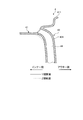
- FIG. 4 is an explanatory view showing the wheel 4 shown in FIG. This figure shows a Y sectional view (solid line portion) and a Z sectional view (broken line portion) of the opening on the rim portion 41 side in the air passage 44 of the wheel 4 shown in FIG.
- the air passages 44 a and 44 b have a plurality of openings on the outer peripheral surface of the rim portion 41. At this time, it is preferable that the openings of the air passages 44 have different cross-sectional shapes. Thereby, the frequency of the air column resonance sound resulting from the installation of the air passage 44 is dispersed, and the noise level is reduced.
- the openings of the air passages 44 have different opening cross-sectional areas and pipe lengths, and are arranged with their opening directions different from each other. At this time, there is no change in the wall shape on the outer side of the wheel 4, and the openings of the air passages 44 are different from each other by changing the internal shape of the rim portion 41 and the wall shape on the inner side of the connecting portion 43. It has a shape.
- the flow rate of each air passage 44 is set to be the same by setting the minimum value of the cross-sectional area of each air passage 44 to be constant.
- the air passage 44 has a plurality of openings on the outer peripheral surface of the rim portion 41, and these openings have mutually different cross-sectional shapes, so that the air column resulting from the installation of the air passage 44 is obtained. There is an advantage that the frequency of the resonance sound is dispersed and the noise level is reduced.
- the cross-sectional area S of the air passage 44 is preferably in the range of 100 [mm 2 ] ⁇ S ⁇ 3000 [mm 2 ].
- the cross-sectional area of the flow path when the valve device 22 of the pressure increasing / decreasing unit 2 is opened the cross-sectional areas of the air passages 111 and 112 formed in the hub unit 11, and the flow paths of the air passages 44a and 44b.
- the cross-sectional area S is preferably in the range of 100 [mm 2 ] to 3000 [mm 2 ].
- these flow path cross-sectional area is more preferably in the range of 120 [mm 2] or more 2500 [mm 2] or less, in 150 [mm 2] or more 2000 [mm 2] within the range of Further preferred.
- the radial width A of the mounting surface of the hub mounting portion 42 is preferably in the range of 35 [mm] ⁇ A ⁇ 100 [mm] (see FIG. 2).
- the radial width A is more preferably in the range of 37 [mm] ⁇ A ⁇ 90 [mm], and further preferably in the range of 40 [mm] ⁇ A ⁇ 80 [mm].
- the pitch circle diameter B of the bolt holes 421 on the mounting surface of the hub mounting portion 42 is in a range of 100 [mm] ⁇ B ⁇ 280 [mm] (see FIG. 2).
- the pitch circle diameter B is more preferably in the range of 110 [mm] ⁇ B ⁇ 260 [mm], and the pitch circle diameter B is in the range of 115 [mm] ⁇ B ⁇ 240 [mm]. More preferably it is.
- the diameter C of the mounting surface of the hub mounting portion 42 be in the range of 140 [mm] ⁇ C ⁇ 300 [mm] (see FIG. 2).
- the diameter C is more preferably in the range of 145 [mm] ⁇ C ⁇ 280 [mm], and the diameter C is further in the range of 150 [mm] ⁇ C ⁇ 260 [mm]. preferable.
- These dimensions A to C are generally defined by the relationship between the hub mounting portion 42 and the hub unit 11 of the vehicle. When these dimensions A to C are within the above range, the opening portion of the air passage 44 and the arrangement region of the bolt hole 421 on the mounting surface of the hub mounting portion 42 are appropriately secured. Further, the relationship between the hub mounting portion 42 and the vehicle hub unit 11 can be optimized.
- FIG. 5 is a configuration diagram illustrating a schematic configuration of an air pressure adjusting device according to another embodiment.
- the air pressure adjusting device 1 a shown in FIG. 5 has the same configuration as the air pressure adjusting device 1 except that the hub unit 110 includes the release valve 16.
- the release valve 16 which is a structure peculiar to the air pressure adjusting device 1a will be described.
- the release valve 16 is formed at a position connected to the air passage 112 of the hub unit 110.
- the release valve 16 is opened to discharge the air in the air passage 112 to the outside.
- the air pressure adjusting device 1a shown in FIG. 5 can discharge the air in the air passage 112 to the outside by opening the release valve 16, and can discharge the air in the air chamber 101.
- the release valve 16 may be provided at one location of the air passage 112 or may be provided at a plurality of locations, for example, at positions corresponding to the air passage 44b.
- the air pressure adjusting device 1a can discharge the air in the air chamber 101 with higher responsiveness by discharging the air in the air chamber 101 with the release valve 16 provided in the air passage 112 of the hub unit 110. . Specifically, since the release valve 16 can open the air passage 112 to the atmosphere at a position close to the air chamber 101, the responsiveness can be increased.
- FIG. 6 is a configuration diagram showing a schematic configuration of an air pressure adjusting device according to another embodiment.
- FIG. 7 is an explanatory view showing the wheel shown in FIG.
- FIG. 8 is an axial sectional view showing the air connection valve of the wheel shown in FIG. 6.
- the air pressure adjusting device 1b shown in FIG. 6 has the same configuration as the air pressure adjusting device 1 except that the hub unit 110a includes release valves 16 and 17 and the wheel 4b includes an air connection valve 45.
- the open valves 16 and 17 and the air connection valve 45 which are unique to the air pressure adjusting device 1b, will be described.
- the release valve 16 has the same configuration as the release valve 16 of the air pressure adjusting device 1a.
- the open valve 17 is formed at a position connected to the air passage 111 of the hub unit 110a.
- the air pressure adjusting device 1b shown in FIG. 6 can discharge the air in the air passage 111 to the outside by opening the release valve 17, and can discharge the air in the air chamber 101.
- the release valve 17 may be provided at one location of the air passage 111 or may be provided at a plurality of locations, for example, at positions corresponding to the air passage 44a.
- the air pressure adjusting device 1b discharges the air in the air chamber 101 with the release valve 17 provided in the air passage 111 of the hub unit 110a in addition to or instead of the release valve 16 provided in the air passage 112 of the hub unit 110a. By doing so, the air in the air chamber 101 can be discharged with higher responsiveness.
- the air connection valve (air coupler) 45 is disposed at the opening on the hub attachment portion 42 side of each of the air passages 44a and 44b of the wheel 4b.
- 8 is an axial cross-sectional view showing the air connection valve of the wheel shown in FIG. The figure shows a state in which the air connection valve 45 is opened.
- the air connection valve 45 includes a plug portion 451, a socket portion 452, and a valve body 453.
- the plug part 451 and the socket part 452 have a short tubular structure.
- the plug portion 451 is inserted into the socket portion 452 so as to be able to move forward and backward, and can be elastically displaced in the axial direction via a coil spring.
- An air passage 454 is formed inside the air connection valve 45 by the tubular structure of the plug portion 451 and the socket portion 452.
- a reduced diameter portion 455 formed by reducing the inner diameters of the plug portion 451 and the socket portion 452 is formed.
- the valve body 453 is a valve body that opens and closes the air passage 454, and can be moved back and forth in the axial direction by being interposed in both the plug portion 451 and the socket portion 452.
- the valve body 453 seals the air passage 454 by engaging with a reduced diameter portion 455 in the air passage 454 (not shown). Further, the valve body 453 opens the air passage 454 by being separated from the reduced diameter portion 455 (see FIG. 8).
- the air connection valve 45 is fixed by fitting the plug portion 451 (or socket portion 452) into the opening of the air passage 44 on the hub attachment portion 42 side, and the socket portion 452 (or plug portion 451) is attached to the hub. It is arranged so as to protrude from the mounting surface of the portion 42.
- the six spokes 431 of the wheel 4 b have air passages 44 that are independent of each other, and air connection valves 45 are respectively provided in the openings of the air passages 44 on the hub mounting portion 42 side. Has been placed. Further, as shown in FIG. 7, in the air pressure adjusting device 1b, two air connection valves 45 are arranged in the openings of one air passages 44a and 44b. Thereby, while ensuring the function of the air connection valve 45, the flow path cross-sectional area of the air passages 44a and 44b is secured.
- the air pressure adjusting device 1b includes an air connection valve (air coupler) 45 that opens the air passage 44 when the wheel 4b is mounted on the vehicle and closes the air passage 44 when the wheel 4b is used alone.
- the air passage 44 communicates and compressed air can be supplied from the pressure-increasing / depressurizing unit 2 to the air chamber 101 of the pneumatic tire 10.
- air can be discharged from the air chamber 101 to the outside.
- the air passage 44 is blocked. Therefore, for example, when the pneumatic tire 10 is inflated and attached to the vehicle, the pneumatic tire 10 is inflated.
- the assembly of the pneumatic tire 10 and the wheel 4b can be transported in a state where is filled.
- FIG. 9 is a configuration diagram showing a schematic configuration of an air pressure adjusting device according to another embodiment.
- FIG. 9 shows an embodiment in which the air pressure adjusting device is applied to a pneumatic tire driven by an in-wheel motor unit.
- the air pressure adjusting device 1c has the same configuration as the air pressure adjusting device 1 except that the vehicle hub unit is integrated with the in-wheel motor unit.
- the air pressure adjusting device 1 c is a device that adjusts the air pressure of the air chamber 101 of the pneumatic tire 10.
- the pressure increasing / decreasing unit 2, the pressure sensor 3, the wheel 4, the control unit 5, and the joint 13 a have the same configuration as each unit of the air pressure adjusting device 1.
- the in-wheel motor unit 6 will be described.
- the in-wheel motor unit 6 also has a function of the hub unit 11 of the air pressure adjusting device 1. That is, the in-wheel motor unit 6 is a drive source that rotates the wheel 4 and the pneumatic tire 10 and is the hub unit 11.
- the in-wheel motor unit 6 is an outer rotor type electric motor in which the rotor 6R is disposed outside the stator 6S.
- the in-wheel motor unit 6 is used in a so-called in-wheel motor system that is attached to a vehicle suspension device.
- the rotor 6 ⁇ / b> R includes a rotor case 61 that is an annular structure, and a permanent magnet 62 that is attached to the inner periphery of the rotor case 61.
- S poles and N poles are alternately arranged in the circumferential direction of the rotor case 61.
- a shaft 65 is attached to the center of the rotor case 61.
- the stator 6S is disposed inside the permanent magnet 62 included in the rotor 6R.
- the stator 6 ⁇ / b> S has a plurality of coils 63 provided on the outer periphery of the stator body 64.
- the stator body 64 has a bearing 66 at the center.
- the shaft 65 described above is supported by the stator main body 64 via the bearing 66. With such a structure, the rotor 6R can rotate around the stator main body 64 around the rotation axis.
- the wheel 4 is attached to the shaft 65 of the rotor 6R.
- the shaft 65 is connected to the joint 13 a in the same manner as the hub unit 11. As with the hub unit 11, the shaft 65 has air passages 111 and 112 formed therein.
- the air passage 111 is connected to the air passage 44 a and the air pipe 24.
- the air passage 112 is connected to the air passage 44 b and the air pipe 25.
- the air passage 111 is similarly formed inside the shaft 65 of the in-wheel motor unit 6. , 112 can provide the same effects as in the above embodiment.
- the air pressure adjusting device 1c is configured such that the in-wheel motor unit 6 is an outer rotor type in which the rotor 6R is disposed on the outer peripheral side, so that the drive mechanism (the rotor 6R, the stator 6S, An area where the speed reduction mechanism is not disposed can be provided. Thereby, the air passages 111 and 112 can be suitably arranged on the rotation axis center side.
Landscapes
- Engineering & Computer Science (AREA)
- Mechanical Engineering (AREA)
- Tires In General (AREA)
- Measuring Fluid Pressure (AREA)
- Arrangement Or Mounting Of Propulsion Units For Vehicles (AREA)
Priority Applications (4)
| Application Number | Priority Date | Filing Date | Title |
|---|---|---|---|
| DE112013001063.1T DE112013001063B4 (de) | 2012-02-21 | 2013-02-13 | Fahrzeugnabeneinheit und Luftdruck-Einstellvorrichtung |
| JP2014500670A JP6070686B2 (ja) | 2012-02-21 | 2013-02-13 | 車両用ハブユニットおよび空気圧調整装置 |
| US14/380,295 US9481214B2 (en) | 2012-02-21 | 2013-02-13 | Vehicle hub unit and air pressure adjusting device |
| CN201380010246.0A CN104125889B (zh) | 2012-02-21 | 2013-02-13 | 车辆用轮毂单元及空气压力调整装置 |
Applications Claiming Priority (2)
| Application Number | Priority Date | Filing Date | Title |
|---|---|---|---|
| JP2012-035625 | 2012-02-21 | ||
| JP2012035625 | 2012-02-21 |
Publications (1)
| Publication Number | Publication Date |
|---|---|
| WO2013125409A1 true WO2013125409A1 (fr) | 2013-08-29 |
Family
ID=49005596
Family Applications (1)
| Application Number | Title | Priority Date | Filing Date |
|---|---|---|---|
| PCT/JP2013/053389 Ceased WO2013125409A1 (fr) | 2012-02-21 | 2013-02-13 | Ensemble moyeu pour véhicule et dispositif de réglage de pression d'air |
Country Status (5)
| Country | Link |
|---|---|
| US (1) | US9481214B2 (fr) |
| JP (1) | JP6070686B2 (fr) |
| CN (1) | CN104125889B (fr) |
| DE (1) | DE112013001063B4 (fr) |
| WO (1) | WO2013125409A1 (fr) |
Cited By (6)
| Publication number | Priority date | Publication date | Assignee | Title |
|---|---|---|---|---|
| GB2516704A (en) * | 2013-07-30 | 2015-02-04 | Jaguar Land Rover Ltd | Vehicle wheel assembly |
| CN104908529A (zh) * | 2015-06-17 | 2015-09-16 | 无锡夕阳康科技有限公司 | 一种轮毂用节油型安全自动调压器 |
| CN105172471A (zh) * | 2015-07-10 | 2015-12-23 | 无锡夕阳康科技有限公司 | 一种带自动调压包的轮毂 |
| EP2974892A3 (fr) * | 2014-07-15 | 2016-03-02 | ArvinMeritor Technology, LLC | Système de gonflage de pneu ayant une soupape de limitation de pression |
| RU201573U1 (ru) * | 2020-10-02 | 2020-12-22 | Сергей Владимирович Чистюнин | Устройство ступичного узла колеса легкового транспортного средства |
| JP2021115906A (ja) * | 2020-01-23 | 2021-08-10 | 株式会社Subaru | 車両、情報処理装置および情報処理システム |
Families Citing this family (21)
| Publication number | Priority date | Publication date | Assignee | Title |
|---|---|---|---|---|
| CN107031275B (zh) * | 2012-02-21 | 2020-09-22 | 横滨橡胶株式会社 | 车轮和空气压力调整装置 |
| JP2017500239A (ja) * | 2013-11-22 | 2017-01-05 | プレッシャーライト(ピーティーワイ)エルティーディー | 車両タイヤの圧力を制御するための装置 |
| US9630461B2 (en) * | 2014-06-27 | 2017-04-25 | GM Global Technology Operations LLC | Pressure system for a tire assembly of a vehicle |
| US20150375577A1 (en) * | 2014-06-27 | 2015-12-31 | GM Global Technology Operations LLC | Pressure system for a tire assembly of a vehicle |
| US9511635B2 (en) * | 2014-07-10 | 2016-12-06 | Airgo Ip, Llc | Apparatus for delivering air through powered axle assemblies |
| EP3201013B1 (fr) * | 2014-10-01 | 2018-08-29 | Bayerische Motoren Werke Aktiengesellschaft | Système et procédé d'alimentation en air comprimé d'une roue d'un véhicule |
| CN104708990A (zh) * | 2015-01-15 | 2015-06-17 | 朱晓义 | 车轮 |
| CN107719035A (zh) * | 2017-10-27 | 2018-02-23 | 绵阳鑫阳知识产权运营有限公司 | 车辆轮毂压力控制系统 |
| CN108284713A (zh) * | 2018-02-22 | 2018-07-17 | 中信戴卡股份有限公司 | 一种轮毂轮胎系统自动恒压装置 |
| EP3590738A1 (fr) * | 2018-07-05 | 2020-01-08 | Vestel Elektronik Sanayi ve Ticaret A.S. | Système de régulation de pression dans un ou plusieurs pneus d'un véhicule |
| JP2020006779A (ja) * | 2018-07-06 | 2020-01-16 | 本田技研工業株式会社 | 車両用ホイール |
| CN109808426A (zh) * | 2019-03-25 | 2019-05-28 | 宋岭林 | 一种车辆自动动态胎压调节系统 |
| CN110217056A (zh) * | 2019-05-31 | 2019-09-10 | 吉林大学 | 一种电动轮轮胎自动充放气装置及其控制方法 |
| CN110341462B (zh) * | 2019-08-14 | 2024-08-20 | 北京中资燕京汽车有限公司 | 具有充放气功能的轮毂电机总成及电驱车轮总成 |
| CN113320339B (zh) * | 2020-02-29 | 2022-05-27 | 关磊 | 一种新能源车辆减速转向及减震防撞系统 |
| CN111319405A (zh) * | 2020-04-08 | 2020-06-23 | 绍兴权电科技有限公司 | 一种外置式胎压监测的减震降噪弹性车轮 |
| CN111319406A (zh) * | 2020-04-08 | 2020-06-23 | 绍兴权电科技有限公司 | 含减震降噪弹性车轮的新能源汽车 |
| CN112968573B (zh) * | 2021-03-04 | 2023-09-12 | 安徽机电职业技术学院 | 一种轮毂电机用防护冷却装置 |
| CN113147275B (zh) * | 2021-05-07 | 2022-10-18 | 浙江阿波罗运动科技股份有限公司 | 一种全地形车 |
| CN115817074A (zh) * | 2022-11-01 | 2023-03-21 | 珠海格力电器股份有限公司 | 轮胎自动胎压控制方法、装置及充/排气泵 |
| CN116619945B (zh) * | 2023-05-18 | 2025-10-28 | 浙江吉利控股集团有限公司 | 车轮结构、车辆、控制方法及装置 |
Citations (4)
| Publication number | Priority date | Publication date | Assignee | Title |
|---|---|---|---|---|
| JPS61169304A (ja) * | 1985-01-21 | 1986-07-31 | Nissan Motor Co Ltd | タイヤ空気圧調整装置のシ−ル機構 |
| JP2000255228A (ja) * | 1999-03-11 | 2000-09-19 | Mitsubishi Automob Eng Co Ltd | タイヤ空気圧調整装置 |
| JP2007176356A (ja) * | 2005-12-28 | 2007-07-12 | Toyota Motor Corp | 空気供給装置 |
| JP2009179170A (ja) * | 2008-01-30 | 2009-08-13 | Toyota Motor Corp | 車両制御装置 |
Family Cites Families (31)
| Publication number | Priority date | Publication date | Assignee | Title |
|---|---|---|---|---|
| DE674267C (de) | 1935-03-23 | 1939-04-11 | Paul Michael | Verfahren zur Veraenderung der Beruehrungsflaeche im Fahrzeughohlreifen |
| US2634781A (en) | 1950-10-30 | 1953-04-14 | Bendix Westinghouse Automotive | Tire inflation control system |
| US2634782A (en) | 1950-10-30 | 1953-04-14 | Bendix Westinghouse Automotive | Tire inflation control system |
| DE1969936U (de) | 1967-05-31 | 1967-10-05 | Michael Smit | Geraet zur luftdruckregelung in kraftfahrzeugreifen. |
| DE1605743A1 (de) | 1967-11-03 | 1971-01-28 | Knorr Bremse Gmbh | Vorrichtung zum Regeln des Reifendruckes von Kraftfahrzeugen |
| JPS561245B2 (fr) * | 1974-03-30 | 1981-01-12 | ||
| US4154279A (en) * | 1975-03-25 | 1979-05-15 | Yasuo Tsuruta | Apparatus for remotely controlling the internal pressure of a pneumatic tire |
| DE3206488A1 (de) | 1982-02-23 | 1983-09-08 | M.A.N. Maschinenfabrik Augsburg-Nürnberg AG, 8000 München | "reifendruck-reguliervorrichtung" |
| GB2178705B (en) | 1985-08-08 | 1989-05-10 | Reynolds Boughton Ltd | Tyre inflate/deflate system |
| US4825925A (en) * | 1988-03-11 | 1989-05-02 | Eaton Corporation | Tire deflation system |
| US4883106A (en) * | 1989-01-19 | 1989-11-28 | Eaton Corporation | Rotary wheel-end assembly for tire inflation system |
| US5221381A (en) * | 1989-06-28 | 1993-06-22 | General Motors Corporation | Vehicle tire pressure management system with easily removed wheel and tire |
| JPH03109110A (ja) * | 1989-09-22 | 1991-05-09 | Isuzu Motors Ltd | タイヤオートインフレータ装置のコントロールバルブ |
| US5398743A (en) * | 1993-09-24 | 1995-03-21 | Tire Inflation Systems Corp. | Tire inflating and deflating system |
| DE4408140C1 (de) | 1994-03-10 | 1995-10-26 | Henry Tunger | Breitreifenrad für ein Kraftfahrzeug |
| JP3556708B2 (ja) * | 1994-08-08 | 2004-08-25 | 株式会社ブリヂストン | タイヤ−リム組立体への内圧充填装置 |
| US5553647A (en) * | 1994-12-14 | 1996-09-10 | Hayes Wheels International, Inc. | Central tire inflation system |
| US5591281A (en) * | 1995-08-09 | 1997-01-07 | Loewe; Richard T. | Flywheel tire inflation device |
| EP1926611B1 (fr) * | 2005-09-23 | 2009-11-11 | PIRELLI TYRE S.p.A. | Surveillance et réglage de pression pour véhicule à deux roues avec réservoir de pression associé à une roue |
| JP4296436B2 (ja) | 2006-01-19 | 2009-07-15 | トヨタ自動車株式会社 | タイヤ空気圧導入装置 |
| DE102006006143A1 (de) * | 2006-02-10 | 2007-08-23 | Schaeffler Kg | Dichtungsanordnung für eine Reifendruck-Reguliereinrichtung |
| JP2009056948A (ja) | 2007-08-31 | 2009-03-19 | Toyota Motor Corp | 空気圧調整システム |
| US20090084481A1 (en) | 2007-10-01 | 2009-04-02 | Kalavitz Michael V | Tire inflation control method and apparatus |
| US8381785B2 (en) * | 2010-05-07 | 2013-02-26 | The Goodyear Tire & Rubber Company | Self-inflating tire assembly |
| CN102019820B (zh) * | 2009-09-22 | 2014-04-09 | 中国北方车辆研究所 | 一种中央充放气系统的气路结构 |
| KR101081015B1 (ko) | 2009-12-01 | 2011-11-09 | 한국타이어 주식회사 | 타이어 내부 공기압 유지장치 |
| US8113254B2 (en) * | 2009-12-21 | 2012-02-14 | The Goodyear Tire & Rubber Company | Self-inflating tire |
| JP5636771B2 (ja) * | 2010-07-01 | 2014-12-10 | 横浜ゴム株式会社 | タイヤ/ホイール組立体及びホイール、並びに圧力調整器 |
| US8235081B2 (en) * | 2010-11-22 | 2012-08-07 | The Goodyear Tire & Rubber Company | In-line pumping assembly for self-inflating tire |
| CN102133842A (zh) * | 2011-03-12 | 2011-07-27 | 张国利 | 汽车轮胎中央充放气装置 |
| CN202138165U (zh) * | 2011-06-12 | 2012-02-08 | 张国利 | 一种具有充放气功能的双气道轮边减速器 |
-
2013
- 2013-02-13 CN CN201380010246.0A patent/CN104125889B/zh active Active
- 2013-02-13 DE DE112013001063.1T patent/DE112013001063B4/de active Active
- 2013-02-13 US US14/380,295 patent/US9481214B2/en active Active
- 2013-02-13 JP JP2014500670A patent/JP6070686B2/ja active Active
- 2013-02-13 WO PCT/JP2013/053389 patent/WO2013125409A1/fr not_active Ceased
Patent Citations (4)
| Publication number | Priority date | Publication date | Assignee | Title |
|---|---|---|---|---|
| JPS61169304A (ja) * | 1985-01-21 | 1986-07-31 | Nissan Motor Co Ltd | タイヤ空気圧調整装置のシ−ル機構 |
| JP2000255228A (ja) * | 1999-03-11 | 2000-09-19 | Mitsubishi Automob Eng Co Ltd | タイヤ空気圧調整装置 |
| JP2007176356A (ja) * | 2005-12-28 | 2007-07-12 | Toyota Motor Corp | 空気供給装置 |
| JP2009179170A (ja) * | 2008-01-30 | 2009-08-13 | Toyota Motor Corp | 車両制御装置 |
Cited By (11)
| Publication number | Priority date | Publication date | Assignee | Title |
|---|---|---|---|---|
| GB2516704A (en) * | 2013-07-30 | 2015-02-04 | Jaguar Land Rover Ltd | Vehicle wheel assembly |
| GB2516704B (en) * | 2013-07-30 | 2016-02-10 | Jaguar Land Rover Ltd | Vehicle wheel assembly |
| US9878586B2 (en) | 2013-07-30 | 2018-01-30 | Jaguar Land Rover Limited | Vehicle wheel assembly |
| EP2974892A3 (fr) * | 2014-07-15 | 2016-03-02 | ArvinMeritor Technology, LLC | Système de gonflage de pneu ayant une soupape de limitation de pression |
| US9352621B2 (en) | 2014-07-15 | 2016-05-31 | Arvinmeritor Technology, Llc | Tire inflation system having a pressure relief valve |
| CN104908529A (zh) * | 2015-06-17 | 2015-09-16 | 无锡夕阳康科技有限公司 | 一种轮毂用节油型安全自动调压器 |
| CN104908529B (zh) * | 2015-06-17 | 2017-09-29 | 江苏锡沂高新区科技发展有限公司 | 一种轮毂用节油型安全自动调压器 |
| CN105172471A (zh) * | 2015-07-10 | 2015-12-23 | 无锡夕阳康科技有限公司 | 一种带自动调压包的轮毂 |
| JP2021115906A (ja) * | 2020-01-23 | 2021-08-10 | 株式会社Subaru | 車両、情報処理装置および情報処理システム |
| JP7437172B2 (ja) | 2020-01-23 | 2024-02-22 | 株式会社Subaru | 車両、情報処理装置および情報処理システム |
| RU201573U1 (ru) * | 2020-10-02 | 2020-12-22 | Сергей Владимирович Чистюнин | Устройство ступичного узла колеса легкового транспортного средства |
Also Published As
| Publication number | Publication date |
|---|---|
| CN104125889A (zh) | 2014-10-29 |
| DE112013001063T5 (de) | 2014-11-06 |
| CN104125889B (zh) | 2016-11-09 |
| JPWO2013125409A1 (ja) | 2015-07-30 |
| US20150013866A1 (en) | 2015-01-15 |
| DE112013001063B4 (de) | 2020-01-23 |
| US9481214B2 (en) | 2016-11-01 |
| JP6070686B2 (ja) | 2017-02-01 |
Similar Documents
| Publication | Publication Date | Title |
|---|---|---|
| JP6070686B2 (ja) | 車両用ハブユニットおよび空気圧調整装置 | |
| JP6176237B2 (ja) | ホイールおよび空気圧調整装置 | |
| JP5948945B2 (ja) | インホイールモータユニットおよび空気圧調整装置 | |
| KR100657129B1 (ko) | 인휠 모터 | |
| JP6883012B2 (ja) | ハブ装置および関連システム | |
| US10035384B2 (en) | Tire inflation system with a passage for routing pressurized gas | |
| US8915274B2 (en) | Spindle for controlling wheel end endplay and preload | |
| US9333813B2 (en) | Tire inflation system having a passage for routing pressurized gas through a flange | |
| US9919569B2 (en) | Tire inflation system having a rotary coupling | |
| JP2012508671A (ja) | 電動モータホイール構造体 | |
| KR20100033375A (ko) | 로드 휠 추진 장치 및 그 제조 방법 | |
| JP2015525160A (ja) | 電気モーター又は発電機システム | |
| KR20170029520A (ko) | 중앙 타이어 팽창 시스템용 회전 밀봉 | |
| US11472226B2 (en) | Lubricant supported electric motor with wheel support | |
| CN106143116A (zh) | 车轮驱动系统 | |
| CN108128142B (zh) | 一种用于电动轮的轮毂轮辋结构、电动轮及车辆 | |
| CN111731092B (zh) | 一种外转子轮辋一体化结构的非充气电动轮 | |
| US10946694B2 (en) | Dual tyre rim | |
| JP2015113076A (ja) | タイヤ・ホイール組立体 | |
| CN119502668A (zh) | 轮毂驱动系统 | |
| WO2022270381A1 (fr) | Dispositif d'alimentation pour véhicule et palier pour roue avec générateur d'énergie | |
| JP2015058873A (ja) | インホイールモータ駆動装置 |
Legal Events
| Date | Code | Title | Description |
|---|---|---|---|
| 121 | Ep: the epo has been informed by wipo that ep was designated in this application |
Ref document number: 13751869 Country of ref document: EP Kind code of ref document: A1 |
|
| ENP | Entry into the national phase |
Ref document number: 2014500670 Country of ref document: JP Kind code of ref document: A |
|
| WWE | Wipo information: entry into national phase |
Ref document number: 14380295 Country of ref document: US Ref document number: 112013001063 Country of ref document: DE Ref document number: 1120130010631 Country of ref document: DE |
|
| 122 | Ep: pct application non-entry in european phase |
Ref document number: 13751869 Country of ref document: EP Kind code of ref document: A1 |