EP3202159B1 - Haut-parleur avec réduction de la coloration audio causée par des réflexions à partir d'une surface - Google Patents
Haut-parleur avec réduction de la coloration audio causée par des réflexions à partir d'une surface Download PDFInfo
- Publication number
- EP3202159B1 EP3202159B1 EP15778540.3A EP15778540A EP3202159B1 EP 3202159 B1 EP3202159 B1 EP 3202159B1 EP 15778540 A EP15778540 A EP 15778540A EP 3202159 B1 EP3202159 B1 EP 3202159B1
- Authority
- EP
- European Patent Office
- Prior art keywords
- transducers
- loudspeaker
- cabinet
- sound
- transducer
- Prior art date
- Legal status (The legal status is an assumption and is not a legal conclusion. Google has not performed a legal analysis and makes no representation as to the accuracy of the status listed.)
- Active
Links
Images


Classifications
-
- H—ELECTRICITY
- H04—ELECTRIC COMMUNICATION TECHNIQUE
- H04R—LOUDSPEAKERS, MICROPHONES, GRAMOPHONE PICK-UPS OR LIKE ACOUSTIC ELECTROMECHANICAL TRANSDUCERS; ELECTRIC HEARING AIDS; PUBLIC ADDRESS SYSTEMS
- H04R1/00—Details of transducers, loudspeakers or microphones
- H04R1/20—Arrangements for obtaining desired frequency or directional characteristics
- H04R1/22—Arrangements for obtaining desired frequency or directional characteristics for obtaining desired frequency characteristic only
- H04R1/28—Transducer mountings or enclosures modified by provision of mechanical or acoustic impedances, e.g. resonator, damping means
- H04R1/2807—Enclosures comprising vibrating or resonating arrangements
- H04R1/2811—Enclosures comprising vibrating or resonating arrangements for loudspeaker transducers
-
- H—ELECTRICITY
- H04—ELECTRIC COMMUNICATION TECHNIQUE
- H04R—LOUDSPEAKERS, MICROPHONES, GRAMOPHONE PICK-UPS OR LIKE ACOUSTIC ELECTROMECHANICAL TRANSDUCERS; ELECTRIC HEARING AIDS; PUBLIC ADDRESS SYSTEMS
- H04R1/00—Details of transducers, loudspeakers or microphones
- H04R1/20—Arrangements for obtaining desired frequency or directional characteristics
- H04R1/32—Arrangements for obtaining desired frequency or directional characteristics for obtaining desired directional characteristic only
- H04R1/40—Arrangements for obtaining desired frequency or directional characteristics for obtaining desired directional characteristic only by combining a number of identical transducers
- H04R1/403—Arrangements for obtaining desired frequency or directional characteristics for obtaining desired directional characteristic only by combining a number of identical transducers loud-speakers
-
- H—ELECTRICITY
- H04—ELECTRIC COMMUNICATION TECHNIQUE
- H04R—LOUDSPEAKERS, MICROPHONES, GRAMOPHONE PICK-UPS OR LIKE ACOUSTIC ELECTROMECHANICAL TRANSDUCERS; ELECTRIC HEARING AIDS; PUBLIC ADDRESS SYSTEMS
- H04R1/00—Details of transducers, loudspeakers or microphones
- H04R1/02—Casings; Cabinets ; Supports therefor; Mountings therein
- H04R1/025—Arrangements for fixing loudspeaker transducers, e.g. in a box, furniture
-
- H—ELECTRICITY
- H04—ELECTRIC COMMUNICATION TECHNIQUE
- H04R—LOUDSPEAKERS, MICROPHONES, GRAMOPHONE PICK-UPS OR LIKE ACOUSTIC ELECTROMECHANICAL TRANSDUCERS; ELECTRIC HEARING AIDS; PUBLIC ADDRESS SYSTEMS
- H04R1/00—Details of transducers, loudspeakers or microphones
- H04R1/20—Arrangements for obtaining desired frequency or directional characteristics
- H04R1/22—Arrangements for obtaining desired frequency or directional characteristics for obtaining desired frequency characteristic only
- H04R1/26—Spatial arrangements of separate transducers responsive to two or more frequency ranges
-
- H—ELECTRICITY
- H04—ELECTRIC COMMUNICATION TECHNIQUE
- H04R—LOUDSPEAKERS, MICROPHONES, GRAMOPHONE PICK-UPS OR LIKE ACOUSTIC ELECTROMECHANICAL TRANSDUCERS; ELECTRIC HEARING AIDS; PUBLIC ADDRESS SYSTEMS
- H04R1/00—Details of transducers, loudspeakers or microphones
- H04R1/20—Arrangements for obtaining desired frequency or directional characteristics
- H04R1/22—Arrangements for obtaining desired frequency or directional characteristics for obtaining desired frequency characteristic only
- H04R1/28—Transducer mountings or enclosures modified by provision of mechanical or acoustic impedances, e.g. resonator, damping means
- H04R1/2803—Transducer mountings or enclosures modified by provision of mechanical or acoustic impedances, e.g. resonator, damping means for loudspeaker transducers
-
- H—ELECTRICITY
- H04—ELECTRIC COMMUNICATION TECHNIQUE
- H04R—LOUDSPEAKERS, MICROPHONES, GRAMOPHONE PICK-UPS OR LIKE ACOUSTIC ELECTROMECHANICAL TRANSDUCERS; ELECTRIC HEARING AIDS; PUBLIC ADDRESS SYSTEMS
- H04R1/00—Details of transducers, loudspeakers or microphones
- H04R1/20—Arrangements for obtaining desired frequency or directional characteristics
- H04R1/22—Arrangements for obtaining desired frequency or directional characteristics for obtaining desired frequency characteristic only
- H04R1/28—Transducer mountings or enclosures modified by provision of mechanical or acoustic impedances, e.g. resonator, damping means
- H04R1/2869—Reduction of undesired resonances, i.e. standing waves within enclosure, or of undesired vibrations, i.e. of the enclosure itself
- H04R1/2876—Reduction of undesired resonances, i.e. standing waves within enclosure, or of undesired vibrations, i.e. of the enclosure itself by means of damping material, e.g. as cladding
- H04R1/288—Reduction of undesired resonances, i.e. standing waves within enclosure, or of undesired vibrations, i.e. of the enclosure itself by means of damping material, e.g. as cladding for loudspeaker transducers
-
- H—ELECTRICITY
- H04—ELECTRIC COMMUNICATION TECHNIQUE
- H04R—LOUDSPEAKERS, MICROPHONES, GRAMOPHONE PICK-UPS OR LIKE ACOUSTIC ELECTROMECHANICAL TRANSDUCERS; ELECTRIC HEARING AIDS; PUBLIC ADDRESS SYSTEMS
- H04R3/00—Circuits for transducers
- H04R3/12—Circuits for transducers for distributing signals to two or more loudspeakers
- H04R3/14—Cross-over networks
-
- H—ELECTRICITY
- H04—ELECTRIC COMMUNICATION TECHNIQUE
- H04R—LOUDSPEAKERS, MICROPHONES, GRAMOPHONE PICK-UPS OR LIKE ACOUSTIC ELECTROMECHANICAL TRANSDUCERS; ELECTRIC HEARING AIDS; PUBLIC ADDRESS SYSTEMS
- H04R2201/00—Details of transducers, loudspeakers or microphones covered by H04R1/00 but not provided for in any of its subgroups
- H04R2201/40—Details of arrangements for obtaining desired directional characteristic by combining a number of identical transducers covered by H04R1/40 but not provided for in any of its subgroups
- H04R2201/401—2D or 3D arrays of transducers
Definitions
- a loudspeaker for reducing the effects caused by reflections off a surface on which the loudspeaker is resting.
- the loudspeaker has individual transducers that are situated to be within a specified distance from the reflective surface, e.g., a baseplate which is to rest on a tabletop or floor surface, such that the travel distances of the reflected sounds and direct sounds from the transducers are nearly equivalent.
- Other embodiments are also described.
- Loudspeakers may be used by computers and home electronics for outputting sound into a listening area.
- a loudspeaker may be composed of multiple electro-acoustic transducers that are arranged in a speaker cabinet.
- the speaker cabinet may be placed on a hard, reflective surface such as a tabletop. If the transducers are in close proximity to the tabletop surface, reflections from the tabletop may cause an undesirable comb filtering effect to a listener. Since the reflected path is longer than the direct path of sound, the reflected sound may arrive later in time than the direct sound. The reflected sound may cause constructive or destructive interference with the direct sound (at the listener's ears), based on phase differences between the two sounds (caused by the delay.)
- WO-A1-2013/124883 discloses a loudspeaker for hanging under a ceiling comprising a plurality of transducers which are adapted to reflect the sound downward radially with constant directivity.
- a loudspeaker is provided with a ring of transducers that are aligned in a plane, within a cabinet.
- the loudspeaker may be designed to be an array where the transducers are all replicates so that each is to produce sound in the same frequency range.
- the loudspeaker may be a multi-way speaker in which not all of the transducers are designed to work in the same frequency range.
- the loudspeaker may include a baseplate coupled to a bottom end of the cabinet.
- the baseplate may be a solid flat structure that is sized to provide stability to the loudspeaker so that the cabinet does not easily topple over while the baseplate is seated on a tabletop or on another surface (e.g., the floor).
- the ring of transducers may be located at a bottom of the cabinet and within a predefined distance from the baseplate, or within a predefined distance from a a tabletop or floor (in the case where no baseplate is used and the bottom end of the cabinet is to rest on the tabletop or floor.)
- the transducers may be angled downward toward the bottom end at a predefined acute angle, so as to reduce comb filtering caused by reflections of sound from the transducer off of the tabletop or floor, in comparison to the transducers being upright.
- Sound emitted by the transducers may be reflected off the baseplate or other reflective surface on which the cabinet is resting, before arriving at the ears of a listener, along with direct sound from the transducers.
- the predefined distance may be selected to ensure that the reflected sound path and the direct sound path are similar, such that comb-filtering effects perceptible by the listener are reduced.
- the predefined distance may be selected based on the size or dimensions of a corresponding transducer or based on the set of audio frequencies to be emitted by the transducer.
- this predefined distance may be achieved through the angling of the transducers downward toward the bottom end of the cabinet. This rotation or tilt may be within a range of values such that the predefined distance is achieved without causing undesired resonance.
- the transducers have been rotated or tilted to an acute angle, e.g., between 37.5° and 42.5°, relative to the bottom end of the cabinet (or if a baseplate is used, relative to the baseplate.)
- the predefined distance may be achieved through the use of horns.
- the horns direct sound from the transducers to sound output openings in the cabinet that are located proximate to the bottom end.
- the predefined distance in this case is between the center of the opening and the tabletop, floor, or baseplate, since the center of the opening is the point at which sound is allowed to propagate into the listening area.
- the predefined distance may be shortened without the need to move or locate the transducers themselves proximate to the bottom end or to the baseplate.
- the loudspeakers described herein may show improved performance over traditional loudspeakers.
- the loudspeakers described here may reduce comb filtering effects perceived by a listener due to either 1) moving transducers closer to a reflective surface on which the loudspeaker may be resting (e.g., the baseplate, or directly on a tabletop or floor) through vertical or rotational adjustments of the transducers or 2) guiding sound produced by the transducers so that the sound is released into the listening area proximate to the reflective surface, through the use of horns and through openings in the cabinet that are at the prescribed distance from the reflective surface.
- the loudspeakers shown and described may be placed on reflective surfaces without severe audio coloration caused by reflected sounds.
- the present invention is defined in claim 1.
- Figure 1 shows a view of a listening area 101 with an audio receiver 103, a loudspeaker 105, and a listener 107.
- the audio receiver 103 may be coupled to the loudspeaker 105 to drive individual transducers 109 in the loudspeaker 105 to emit various sound beam patterns into the listening area 101.
- the loudspeaker 105 may be configured and is to be driven as a loudspeaker array, to generate beam patterns that represent individual channels of a piece of sound program content.
- the loudspeaker 105 (as an array) may generate beam patterns that represent front left, front right, and front center channels for a piece of sound program content (e.g., a musical composition or an audio track for a movie).
- the loudspeaker 105 has a cabinet 111, and the transducers 109 are housed in a bottom 102 of the cabinet 111 and to which a baseplate 113 is coupled as shown.
- FIG. 2A shows a component diagram of the audio receiver 103 according to one embodiment.
- the audio receiver 103 may be any electronic device that is capable of driving one or more transducers 109 in the loudspeaker 105.
- the audio receiver 103 may be a desktop computer, a laptop computer, a tablet computer, a home theater receiver, a set-top box, or a smartphone.
- the audio receiver 103 may include a hardware processor 201 and a memory unit 203.
- the processor 201 and the memory unit 203 are generically used here to refer to any suitable combination of programmable data processing components and data storage that conduct the operations needed to implement the various functions and operations of the audio receiver 103.
- the processor 201 may be an applications processor typically found in a smart phone, while the memory unit 203 may refer to microelectronic, non-volatile random access memory.
- An operating system may be stored in the memory unit 203 along with application programs specific to the various functions of the audio receiver 103, which are to be run or executed by the processor 201 to perform the various functions of the audio receiver 103.
- the audio receiver 103 may include one or more audio inputs 205 for receiving multiple audio signals from an external or remote device.
- the audio receiver 103 may receive audio signals as part of a streaming media service from a remote server.
- the processor 201 may decode a locally stored music or movie file to obtain the audio signals.
- the audio signals may represent one or more channels of a piece of sound program content (e.g., a musical composition or an audio track for a movie).
- a single signal corresponding to a single channel of a piece of multichannel sound program content may be received by an input 205 of the audio receiver 103, and in that case multiple inputs may be needed to receive the multiple channels for the piece of content.
- a single signal may correspond to or have encoded therein or multiplexed therein the multiple channels (of the piece of sound program content),.
- the audio receiver 103 may include a digital audio input 205A that receives one or more digital audio signals from an external device or a remote device.
- the audio input 205A may be a TOSLINK connector, or it may be a digital wireless interface (e.g., a wireless local area network (WLAN) adapter or a Bluetooth adapter).
- the audio receiver 103 may include an analog audio input 205B that receives one or more analog audio signals from an external device.
- the audio input 205B may be a binding post, a Fahnestock clip, or a phono plug that is designed to receive a wire or conduit and a corresponding analog signal.
- the audio receiver 103 may include an interface 207 for communicating with the loudspeaker 105.
- the interface 207 may utilize wired mediums (e.g., conduit or wire) to communicate with the loudspeaker 105, as shown in Figure 1 .
- the interface 207 may communicate with the loudspeaker 105 through a wireless connection.
- the network interface 207 may utilize one or more wireless protocols and standards for communicating with the loudspeaker 105, including the IEEE 802.11 suite of standards, IEEE 802.3, cellular Global System for Mobile Communications (GSM) standards, cellular Code Division Multiple Access (CDMA) standards, Long Term Evolution (LTE) standards, and/or Bluetooth standards.
- GSM Global System for Mobile Communications
- CDMA Code Division Multiple Access
- LTE Long Term Evolution
- the loudspeaker 105 may receive transducer drive signals from the audio receiver 103 through a corresponding interface 213.
- the interface 213 may utilize wired protocols and standards and/or one or more wireless protocols and standards, including the IEEE 802.11 suite of standards, IEEE 802.3, cellular Global System for Mobile Communications (GSM) standards, cellular Code Division Multiple Access (CDMA) standards, Long Term Evolution (LTE) standards, and/or Bluetooth standards.
- GSM Global System for Mobile Communications
- CDMA Code Division Multiple Access
- LTE Long Term Evolution
- the drive signals are received in digital form, and so in order drive the transducers 109 the loudspeaker 105 in that case may include digital-to-analog converters (DACs) 209 that are coupled in front of the power amplifiers 211, for converting the drive signals into analog form before amplifying them to drive each transducer 109.
- DACs digital-to-analog converters
- the loudspeaker 105 may also include, within its cabinet 111, the hardware processor 201, the memory unit 203, and the one or more audio inputs 205.
- the loudspeaker 105 houses multiple transducers 109 in a speaker cabinet 111, which may be aligned in a ring formation relative to each other, to form a loudspeaker array.
- the cabinet 111 as shown is cylindrical; however, in other embodiments the cabinet 111 may be in any shape, including a polyhedron, a frustum, a cone, a pyramid, a triangular prism, a hexagonal prism, a sphere, a frusto conical shape, or any other similar shape.
- the cabinet 111 may be at least partially hollow, and may also allow the mounting of transducers 109 on its inside surface or on its outside surface.
- the cabinet 111 may be made of any suitable material, including metals, metal alloys, plastic polymers, or some combination thereof.
- the loudspeaker 105 may include a number of transducers 109.
- the transducers 109 may be any combination of full-range drivers, mid-range drivers, subwoofers, woofers, and tweeters.
- Each of the transducers 109 may have a diaphragm or cone that is connected to a rigid basket or frame via a flexible suspension that constrains a coil of wire (e.g., a voice coil) that is attached to the diaphragm to move axially through a generally cylindrical magnetic gap.
- a coil of wire e.g., a voice coil
- the coil and the transducers' 109 magnetic system interact, generating a mechanical force that causes the coil (and thus, the attached cone) to move back and forth, thereby reproducing sound under the control of the applied electrical audio signal coming from an audio source, such as the audio receiver 103.
- electromagnetic dynamic loudspeaker drivers are described for use as the transducers 109, those skilled in the art will recognize that other types of loudspeaker drivers, such as piezoelectric, planar electromagnetic and electrostatic drivers are possible.
- Each transducer 109 may be individually and separately driven to produce sound in response to separate and discrete audio signals received from an audio source (e.g., the audio receiver 103).
- the loudspeaker 105 may be arranged and driven as an array, to produce numerous directivity or beam patterns that accurately represent each channel of a piece of sound program content output by the audio receiver 103.
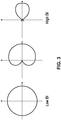
- the loudspeaker 105 may be arranged and driven as an array, to produce one or more of the directivity patterns shown in Figure 3 .
- Simultaneous directivity patterns produced by the loudspeaker 105 may not only differ in shape, but may also differ in direction. For example, different directivity patterns may be pointed in different directions in the listening area 101.
- the transducer drive signals needed to produce the desired directivity patters may be generated by the processor 201 (see Figure 2A ) executing a beamforming process.
- a system has been described above in relation to a number of transducers 109 that may be arranged and driven as part of a loudspeaker array, the system may also work with only a single transducer (housed in a cabinet 111.)
- a non-array loudspeaker may be configured or used in a similar fashion described herein.
- the loudspeaker 105 may include a single ring of transducers 109 arranged to be driven as an array.
- each of the transducers 109 in the ring of transducers 109 may be of the same type or model, e.g. replicates.
- the ring of transducers 109 may be oriented to emit sound "outward" from the ring, and may be aligned along (or lying in) a horizontal plane such that each of the transducers 109 is vertically equidistant from the tabletop, or from a top plane of a baseplate 113 of the loudspeaker 105.
- sound emitted by the transducers 109 may be spread vertically with minimal limitation.
- the head or ears of the listener 107 are located approximately one meter and at a twenty degree angle relative to the ring of transducers 109 in the loudspeaker 105.
- the spread of sound from the loudspeaker 105 may include sound emitted 1) downward and onto a tabletop on which the loudspeaker 105 has been placed and 2) directly at the listener 107.
- the sound emitted towards the tabletop will be reflected off the surface of the tabletop and towards the listener 107. Accordingly, both reflected and direct sound from the loudspeaker 105 may be sensed by the listener 107.
- a comb filtering effect may be detected or perceived by the listener 107.
- a comb filtering effect may be defined as the creation of peaks and troughs in frequency response that are caused when signals that are identical but have phase differences are summed. An undesirably colored sound can result from the summing of these signals.
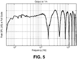
- Figure 5 shows a logarithmic sound pressure versus frequency graph for sound detected at one meter and at twenty degrees relative to the loudspeaker 105 (i.e., the position of the listener 107 as shown in Figure 4 ).
- a set of bumps or peaks and notches or troughs illustrative of this comb filtering effect may be observed in the graph shown in Figure 5 .
- the bumps may correspond to frequencies where the reflected sounds are in-phase with the direct sounds while the notches may correspond to frequencies where the reflected sounds are out-of-phase with the direct sounds.
- bumps and notches may move with elevation or angle (degree) change, as path length differences between direct and reflected sound changes rapidly based on movement of the listener 107.
- the listener 107 may stand up such that the listener 107 is at a thirty degree angle or elevation relative to the loudspeaker 105 as shown in Figure 6 instead of a twenty degree elevation as shown in Figure 4 .
- the sound pressure vs. frequency as measured at the thirty degree angle (elevation) is shown in Fig. 7 . It can be seen that the bumps and notches in the sound pressure versus frequency behavior move with changing elevation, and this is illustrated in the contour graph of Figure 8 which shows the comb filtering effect of Figures 5 and 7 as witnessed from different angles.
- the regions with darker shading represent high SPL (bumps), while the regions with lighter shading represent low SPL (notches).
- the bumps and notches shift over frequency, as the listener 107 changes angles/location relative to the loudspeaker 105. Accordingly, as the listener 107 moves in the vertical direction relative to the loudspeaker 105, the perception of sound for this listener 107 changes. This lack of consistency in sound during movement of the listener 107, or at different elevations, may be undesirable.
- the distance between reflected sounds and direct sounds may be shortened.
- the ring of transducers 109 may be oriented such that sound emitted by the transducers 109 travels a shorter or even minimal distance, before reflection on the tabletop or another reflective surface. This reduced distance will result in a shorter delay between direct and reflected sounds, which consequently will lead to more consistent sound at locations/angles the listener 107 is most likely to be situated. Techniques for minimizing the difference between reflected and direct paths from the transducers 109 will be described in greater detail below by way of example.
- FIG 9A shows a loudspeaker 105 in which an integrated transducer 109 has been moved closer to the bottom of the cabinet 111 than its top, in comparison to the transducer 109 in the loudspeaker 105 shown in Figure 4 .
- the transducer 109 may be located proximate to a baseplate 113 that is fixed to a bottom end of the cabinet 111 of the loudspeaker 105.
- the baseplate 113 may be a solid flat structure that is sized to provide stability to the loudspeaker 105 while the loudspeaker 105 is seated on a table or on another surface (e.g., a floor), so that the cabinet 111 can remain upright.
- the baseplate 113 may be sized to receive sounds emitted by the transducer 109 such that sounds may be reflected off of the baseplate 113.
- sounds may be reflected off of the baseplate 113.
- the baseplate 113 may be described as being coupled to a bottom 102 of the cabinet 111, e.g., directly to its bottom end, and may extend outward beyond a vertical projection of the outermost point of a sidewall of the cabinet.
- the baseplate 113 may be the same diameter of the cabinet 111.
- the bottom 102 of the cabinet 111 may curve or cut inwards (e.g., until it reaches the baseplate 113) and the transducers 109 may be located in this curved or cutout section of the bottom 102 of the cabinet 111 such as shown in Figure 1 .
- an absorptive material 901 such as foam, may be placed around the baseplate 113, or around the transducers 109.
- a slot 903 may be formed in the cabinet 111, between the transducer 109 and the baseplate 113.
- the absorptive material 901 within the slot 903 may reduce the amount of sound that has been reflected off of the baseplate 113 in a direction opposite the listener 107 (and that would otherwise then be reflected off of the cabinet 111 back towards the listener 107).
- the slot 903 may encircle the cabinet 111 around the base of the cabinet 111 and may be tuned to provide a resonance in a particular frequency range to further reduce sound reflections.
- the slot 903 may form a resonator coated with the absorptive material 901 designed to dampen sounds in a particular frequency range to further eliminate sound reflections off the cabinet 111.
- a screen 905 may be placed below the transducers 109.
- the screen 905 may be a perforated mesh (e.g., a metal, metal alloy, or plastic) that functions as a low-pass filter for sound emitted by the transducers 109.
- the screen 905 may create a cavity 907 (similar to the slot 903 depicted in Figure 9C ) underneath the cabinet 111 between the baseplate 113 and the transducers 109. High-frequency sounds emitted by the transducers 109 and which reflect off the cabinet 111 may be attenuated by the screen 905 and prevented from passing into the listening area 101.
- the porosity of the screen 905 may be adjusted to limit the frequencies that may be free to enter the listening area 101.
- the vertical distance D between a center of the diaphragm of the transducer 109 and a reflective surface may be between 8.0 mm and 13.0 mm as shown in Figure 9B .
- the distance D may be 8.5 mm, while in other embodiments the distance D may be 11.5 mm (or anywhere in between 8.5 mm - 11.5 mm). In other embodiments, the distance D may be between 4.0 mm and 20.0 mm.
- the loudspeaker 105 may exhibit a reduced length of its reflected sound path. This reduced reflected sound path consequently reduces the difference between the lengths of the reflected sound path and the direct sound path, for sound originating from a transducer 109 integrated within the cabinet 111, e.g., the difference, reflected sound path distance - direct sound path distance, approaches zero).
- each transducer 109 in a ring formation of multiple transducers 109 may be similarly arranged, along the side or face of the cabinet 111.
- the ring of transducers 109 may be aligned along or lie within a horizontal plane as described above.
- the distance D or the range of values used for the distance D may be selected based on the radius of the corresponding transducer 109 (e.g., the radius of the diaphragm of the transducer 109) or the range of frequencies used for the transducer 109.
- high frequency sounds may be more susceptible to comb filtering caused by reflections.
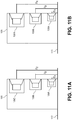
- FIG. 11A shows a multi-way loudspeaker 105 with a first transducer 109A used/designed for a first set of frequencies, a second transducer 109B used/designed for a second set of frequencies, and a third transducer 109C used/designed for a third set of frequencies.
- the first transducer 109A may be used/designed for high frequency content (e.g., 5kHz-10kHz)
- the second transducer 109B may be used/designed for mid frequency content (e.g., 1kHz-5kHz)
- the third transducer 109C may be used/designed for low frequency content (e.g., 100Hz-1kHz).
- These frequency ranges for each of the transducers 109A, 109B, and 109C may be enforced using a set of filters integrated within the loudspeaker 105.
- the distance D A associated with the transducer 109A may be smaller than the distances D B and D C associated with the transducers 109B and 109C, respectively (e.g., the transducers 109B and 109C may be located farther from a reflective surface on which the loudspeaker 105 is resting, without notches associated with comb filtering falling within their bandwidth of operation). Accordingly, the distance D between transducers 109 and a reflective surface needed to reduce comb filtering effects may be based on the size/diameter of the transducers 109 and/or the frequencies intended to be reproduced by the transducers 109.
- the multi-way loudspeaker 105 shown in Figure 11A may include rings of each of the transducers 109A, 109B, and 109C. Each ring of the transducers 109A, 109B, and 109C may be aligned in separate horizontal planes.
- the loudspeaker 105 may include any number of different types of transducers 109.
- the loudspeaker 105 may be an N-way array as shown in Figure 11B , where N is an integer that is greater than or equal to one.
- the distances D A - D N associated with each ring of transducers 109A-109N may be based on the size/diameter of the transducers 109A-109N and/or the frequencies intended to be reproduced by the transducers 109A-109N.
- achieving a small distance D i.e., a value within a range described above
- a reflective surface i.e., arranging transducers 109 along the cabinet 111 to be closer to the baseplate 113
- the ability to achieve values for the distance D within prescribed ranges may be difficult or impossible.
- a threshold value for D it would be impossible to achieve a threshold value for D by simply moving a transducer 109 in the vertical direction along the face of the cabinet 111 closer to the reflective surface when the radius of the transducer 109 is greater than the threshold value for D (e.g., the threshold value is 12.0 mm and the radius of the transducer 109 is 13.0mm). In these situations, additional degrees of freedom of movement may be employed to achieve the threshold value for D as described below.
- the orientation of the transducers 109 in the loudspeaker 105 may be adjusted to further reduce the distance D between the transducer 109 and the reflective surface, reduce the reflected sound path, and consequently reduce the difference between the reflected and direct sound paths.
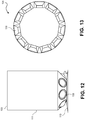
- Figure 12 shows a side view of a loudspeaker 105 according to one embodiment. Similar to the loudspeaker 105 of Figure 9 , the loudspeaker 105 shown in Figure 12 includes a ring of transducers 109 situated in or around the bottom of the cabinet 111 and near the baseplate 113. The ring of transducers 109 may encircle the circumference of the cabinet 111 (or may be coaxial with the circumference), with equal spacing between each adjacent pairs of transducers 109 as shown in the overhead cutaway view in Figure 13 .
- the transducers 109 are located proximate to the baseplate 113, by being mounted in the bottom 102 of the cabinet 111.
- the bottom in this example is frusto conical as shown having a sidewall that joins an upper base and a lower base, and wherein the upper base is larger than the lower base and the base plate 113 is coupled to the lower base as shown.
- Each of the transducers 109 in this case may be described as being mounted within a respective opening in the sidewall such that its diaphragm is essentially outside the cabinet 111, or is at least plainly visible along a line of sight, from outside of the cabinet 111.
- the indicated distance D being the vertical distance from the center of the diaphragm, e.g., the center of its outer surface, down to the top of the baseplate 113.
- the sidewall (of the bottom 102) has a number of openings formed therein that are arranged in a ring formation and in which the transducers 109 have been mounted, respectively.
- by positioning the transducers 109 close to a surface upon which sound from the transducers 109 is reflected e.g., by minimizing the distance D while restricting the angle theta.
- the angle theta may be defined as depicted in that figure, namely as the angle between 1) a plane of the diaphragm of the transducer 109, such as a plane in which a perimeter of the diaphragm lies, and 2) the tabletop surface, or if a baseplate 113 is used then a horizontal plane that touches the top of the base plate 113.)
- the angle theta of each of the transducers 109 may be restricted to a specified range, so that the difference between the path of reflected sounds and the path of direct sounds may be reduced, in comparison to the upright arrangement of the transducer 109 shown in Figure 14a .
- a transducer 109 that is not angled downward is shown in Figure 14A , where it may be described as being upright or “directly facing" the listener 107, defining an angle theta of at least ninety degrees, and a distance D 1 between the center of the transducer 109 and a reflective surface below, e.g., a tabletop or the top of the baseplate 113.
- angling the transducer 109 downward at an acute angle theta ( ⁇ ) results in a distance D 2 between the center of the transducer 109 and a reflective surface, where D 2 ⁇ D 1 .
- the distance D between the center of the transducer 109 and the reflective surface decreases (because the bottommost edge of the diaphragm remains fixed between Figure 14A and Figure 14B , e.g., as close as possible to the reflective surface.)
- this reduction in D results in a reduction in the difference between the direct and reflected sounds paths and a consequent reduction in audio coloration caused by comb filtering.
- the reduction in the reflected sound path may be seen in Figure 14C , where the solid line from the non-rotated transducer 109 is longer than the dashed line from the transducer 109 that is tilted by an angle theta, ⁇ .
- the transducer 109 may be angled downward toward the baseplate 113 as explained above and also as shown in Figure 12 .
- the distance D is a vertical distance between the diaphragm of each of the transducers 109 and a reflective surface (e.g., the baseplate 113). In some embodiments, this distance D may be measured from the center of the diaphragm to the reflective surface. Although shown with both protruding diaphragms and flat diaphragms, in some embodiments inverted diaphragms may be used. In these embodiments, the distance D may be measured from the center of the inverted diaphragm, or from the center as it has been projected onto a plane of the diaphragm along a normal to the plane, where the diaphragm plane may be a plane in which the perimeter of the diaphragm lies. Another plane associated with the transducer may be a plane that is defined by the front face of the transducer 109 (irrespective of the inverted curvature of its diaphragm).
- the transducers 109 may be rotated or tilted between 30.0° and 50.0° (e.g., ⁇ as defined above in Figure 14B may be between 30.0° and 50.0°).
- the transducers 109 may be rotated between 37.5° and 42.5° (e.g., ⁇ may be between 37.5° and 42.5°). In other embodiments, the transducers 109 may be rotated between 39.0° and 41.0°. The angle theta of rotation of the transducers 109 may be based on a desired or threshold distance D for the transducers 109.
- Figure 15A shows a logarithmic sound pressure versus frequency graph for sound detected at a position (of the listener 107) along a direct path that is one meter away from the loudspeaker 105, and twenty degrees upward from the horizontal - see Figure 4 .
- the graph of Figure 15A represents sound emitted by the loudspeaker 105 shown in Figure 12 with a degree of rotation theta of the transducers 109 at 45°. In this graph, sound levels are relatively consistent within the audible range (i.e., 20Hz to 10kHz).
- the contour graph of Figure 15B for a single transducer 109 shows relative consistency in the vertical direction, for most angles at which the listener 107 would be located.
- a linear response is shown in the contour graph of Figure 15B for a vertical position of the listener 107 being 0° (the listener 107 is seated directly in front of the loudspeaker 105) and for a vertical position between 45° and 60° (the listener 107 is standing up near the loudspeaker 105).
- notches in this counter graph have been mostly moved outside the audible range, or they have been moved to vertical angles where the listener 107 is not likely to be located (e.g., the listener 107 would not likely be standing directly above the loudspeaker 105, at the vertical angle of 90°).
- the degree of rotation or the range of rotation may be set based on the set of frequencies and the size or diameter of the transducers 109.
- larger transducers 109 may produce sound waves with larger wavelengths. Accordingly, the distance D needed to mitigate comb filtering for these larger transducers 109 may be longer than the distance D needed to mitigate comb filtering for smaller transducers 109.
- the corresponding angle ⁇ at which the transducers are tilted, as needed to achieve this longer distance D may be larger (less tilting or rotation is needed), in order avoid over-rotation (or over-tilting). Accordingly, the angle of rotation ⁇ for a transducer 109 may be selected based on the diaphragm size or diameter of the transducers 109 and the set of frequencies desired to be output by the transducer 109.
- positioning and angling the transducers 109 along the face of the cabinet 111 of the loudspeaker 105 may reduce a reflective sound path distance, reduce a difference between a reflective sound path and a direct sound path, and consequently reduce comb filtering effects.
- horns may be utilized to further reduce comb filtering.
- a horn enables the point at which sound escapes from (an opening in) the cabinet 111 of the loudspeaker 105 (and then moves along respective direct and reflective paths toward the listener 107) to be adjusted.
- the point of release of sound from the cabinet 111 and into the listening area 101 may be configured during manufacture of the loudspeaker 105 to be proximate to a reflective surface (e.g., the baseplate 113).
- a reflective surface e.g., the baseplate 113.
- Each of these configurations may allow use of larger transducers 109 (e.g., larger diameter diaphragms), or a greater number or a fewer transducers 109, while still reducing comb filtering effects and maintaining a small cabinet 111 for the loudspeaker 105.
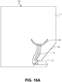
- Figure 16A shows a cutaway side view of the cabinet 111 of the loudspeaker 105 having a horn 115 and no baseplate 113.
- Figure 16B shows an elevation or perspective view of the loudspeaker 105 of Figure 16A configured as, and to be driven as, an array having multiple transducers 109 arranged in a ring formation.
- the transducer 109 is mounted or located further inside or within the cabinet 111 (rather than within an opening in the sidewall of the cabinet 111), and a horn 115 is provided to acoustically connect the diaphragm of the transducer 109 to a sound output opening 117 of the cabinet 111.
- the transducer 109 In contrast to the embodiment of Figure 9D where the transducer 109 is mounted within an opening in the sidewall of the cabinet 111 and is visible from the outside, there is no "line of sight" to the transducer 109 in Figures 16A , 16B from outside of the cabinet 111.
- the horn 115 extends downward from the transducer 109, to the opening 117, which is formed in the sloped sidewall of the bottom 102 of the cabinet 111 which lies on a tabletop or floor. In this example, the bottom 102 is frusto conical.
- the horn 115 directs sound from the transducer 109 to an inside surface of the sidewall of the cabinet 111 where the opening 117 is located, at which point the sound is then released into the listening area through the opening 117.
- the transducer may still be closer to the bottom end of the cabinet 111 than it top end, the transducer 109 is in a raised position (above the bottom end) in contrast to the embodiment of Fig. 12 . Nevertheless, sound emitted by the transducer 109 can still be released from the cabinet 111 at a point that is "proximate" or close enough to the reflective surface underneath. That is because the sound is released from an opening 117 which itself is positioned in close proximity to the baseplate 113.
- the opening 117 may be positioned and oriented to achieve the same vertical distance D that was described above in connection with the embodiments of Figures 9B , 12 , 14B (in which the distance D was being measured between the diaphragm and the reflective surface below the cabinet 111.)
- the predefined vertical distance D (from the center of the opening 117 vertically down to the tabletop or floor on which the cabinet 111 is resting) may be for example between 8.0 millimeters and 13.0 millimeters.
- the distance D may be achieved in part by inclining the opening 117 (analogous to the rotation or tilt angle theta of Figure 14B ), for example, appropriately defining the angle or slope of the sidewall of the frusto-conical bottom 102 (of the cabinet 111) in which the opening 117 is formed.
- the horn 115 and the opening 117 may be formed in various sizes to accommodate sound produced by the transducers 109.
- multiple transducers 109 in the loudspeaker 105 may be similarly configured with corresponding horns 115 and openings 117 in the cabinet 111, together configured, and to be driven as, an array.
- the sound from each transducer 109 is released from the cabinet 111 at a prescribed distance D from the reflective surface below the cabinet 111 (e.g., a tabletop or a floor on which the cabinet 111 is resting, or a baseplate 113). This distance D may be measured from the center of the opening 117 (vertically downward) to the reflective surface.
- reflected sound may travel along a path similar to that of direct sound as described above.
- the difference in the reflected and direct sound paths may be small, which results in a reduction in comb filtering effects perceptible to the listener 107.
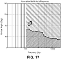
- the contour graph of Figure 17 corresponding to the loudspeaker 105 shown in Figures 16A and 16B shows a smooth and consistent level difference across frequencies and vertical angles (which are angles that define the possible vertical positions of the listener 107), in comparison to the comb filtering effect shown in Figure 8 .
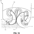
- Figure 18 shows a cutaway view of the cabinet 111 of the loudspeaker 105, according to another horn embodiment.
- the transducers 109 are mounted to or through the sidewall of the cabinet 111, but are pointed inward (rather than outward as in the embodiment of Figure 9D , for example.
- the forward faces of their diaphragms are facing into the cabinet 111.
- Corresponding horns 115 are acoustically coupled to the front faces of diaphragms of the transducers 109, respectively, and extend downward along respective curves to corresponding openings 117.
- the curvature of the horns 115A allow sound to be emitted from the openings 117, which are aimed to emit sound into the listening area 101 in a second direction (different than the first direction).
- the openings 117 of the cabinet 111 in this embodiment may be positioned and oriented the same as described above in connection with the horn embodiments of Figures 16A , 16B .
- a phase plug 119 may be added into the acoustic path between the transducer 109 and its respective opening 117, as shown, so as to redirect high frequency sounds to avoid reflections and cancellations.
- the contour graph of Figure 19 corresponding to the loudspeaker 105 of Figure 18 shows a smooth and consistent level difference across frequencies and vertical listening positions (vertical direction angles), in comparison to the undesirable comb filtering effects shown in Figure 8 .
- Figure 20 shows a cutaway view of the cabinet 111 of the loudspeaker 105, according to yet another embodiment.
- the transducers 109 are also mounted within the cabinet 111 but they are pointed downwards (rather than sideways as in the embodiment of Figure 18 in which the transducers 109 may be mounted to the sidewall of the cabinet 111).
- This arrangement may enable the use of horns 115 that are shorter than those in the embodiment of Figure 18 .
- the shorter horns 115 may contribute to a smoother response by this embodiment, in comparison to the other embodiments that also use horns 115 (described above.)
- the length of the horns 115 may be between 20.0 mm and 45.0 mm.
- the openings 117 of the cabinet 111 in this embodiment may also be formed in the sloped sidewall of the frusto-conical bottom 102 of the cabinet 111, and may be positioned and oriented the same as described above in connection with the horn embodiments of Figures 16A , 16B to achieve a smaller distance D relative to the reflective surface, e.g., the top surface of the baseplate 113.
- FIG 22 shows a cutaway view of the cabinet 111 in the loudspeaker 105, according to yet another embodiment.
- each of the transducers 109 is mounted within the cabinet 111, e.g., similar to Figure 20 , but the horn 115 (which directs sound emitted from its respective transducer 109 to its respective opening 117) is longer and narrower than in Figure 20 .
- a combination of one or more Helmholtz resonators 121 may be used for each respective transducer 109 (e.g., an 800Hz resonator, a 3kHz resonator, or both) along with phase plugs 119.
- the resonators 121 may be aligned along the horn 115 or just outside the opening 117, for absorbing sound and reducing reflections. As shown in the contour graph of Figure 23 , the longer, narrower horns 115 of this embodiment, together with 800Hz and 3kHz Helmholtz resonators 121 may result in a smooth frequency response (at various angles in the vertical direction).
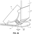
- Figure 24 shows a cutaway or cross section view taken of a combination transducer 109 and its phase plug 119, in the cabinet 111 of the loudspeaker 105, according to another embodiment.
- the phase plug 119 is placed adjacent to its respective transducer 109, and each such combination transducer 109 and phase plug 119 may be located entirely within (inward of the sidewall of) the cabinet 111 as shown.
- a shielding device 2401 that is coupled to the outside surface of the cabinet 111 or also to the baseplate 113 may hold the phase plug 119 in position against its transducer 109.
- the shielding device 2401 may extend around the perimeter or circumference of the cabinet 111, forming a ring that serves to hold all of the phase plugs 119 of all of the transducers 109 (e.g., in the case of a loudspeaker array).
- the phase plug 119 may be formed as several fins 2403 that extend from a center hub 2405.
- the fins 2403 may guide sound (through the spaces between adjacent ones of the fins 2403) from the diaphragm of the corresponding transducer 109 to an aperture 2407 formed in the shielding device 2401.
- the phase plug 119 may be shaped to surround the transducer 109, including a diaphragm of the transducer 109 as shown, such that sound may be channeled from the transducers 109 to the aperture 2407.
- the phase plugs 119 of this embodiment are also able to place the effective sound radiation area of the transducers 109 closer to the reflective surface (e.g., the baseplate 113, or a tabletop on which the loudspeaker 105 is resting).
- the loudspeaker 105 in this embodiment may reduce the difference between reflective and direct sound paths, which in turn may reduce comb filtering effects.
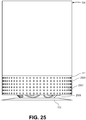
- the loudspeaker 105 has a partition 2501.
- the partition 2501 may made of a rigid material (e.g., a metal, metal alloy, or plastic) and extends from the outside surface of the cabinet 111 over the bottom 102 of the cabinet 111, to partially block the transducers 109 - see Figure 12 which shows an example of the bottom 102 of the cabinet 111 and the transducers 109 therein, which would be blocked by the partition 2501 of Figure 25 .
- a rigid material e.g., a metal, metal alloy, or plastic
- the partition 2501 in this example is a simple cylinder (extending straight downward) but it could alternatively have a different curved shape, e.g., wavy like a skirt or curtain, to encircle the cabinet 111 and partially block each of the transducers 109.
- the partition 2501 may include a number of holes 2503 formed in its curved sidewall as shown which may be sized to allow the passage of various desired frequencies of sound.
- one group or subset of the holes 2503 which are located farthest from the baseplate 113 may be sized to allow the passage of low-frequency sounds (e.g., 100Hz-1kHz) while another group or subset of holes 2503 that lies below the low-frequency holes may be sized to allow the passage of mid-frequency sounds (e.g., 1kHz-5kHz).
- high-frequency sounds may pass between a gap 2505 created between the bottom end of the partition 2501 and the baseplate 113. Accordingly, high-frequency content is pushed closer to the baseplate 113 by restricting this content to the gap 2505.
- FIGS. 26A , 26B these illustrate the use of acoustic dividers 2601 in a multi-way version, or in an array version, of the loudspeaker 105, in accordance with yet another embodiment of the invention.
- the divider 2601 may be a flat piece that forms a wall joining the bottom 102 of the cabinet 111 to the baseplate 113, as best seen in the side view of Fig. 26B .
- the divider 2601 begins at the transducer 109 and extends outward lengthwise, e.g., until a horizontal length given by the radius r, which extends from a center of the cabinet (through which a vertical longitudinal axis of the cabinet 111 runs - see Fig. 26b .
- the divider 2601 need not reach the vertical boundary defined by the outermost sidewall of the cabinet 111, as shown.
- a pair of adjacent dividers 2601 on either side of a transducer 109 may, together with the surface of the bottom 102 of the cabinet 111 and the top surface of the baseplate, act like a horn for the transducer 109.
- the loudspeakers 105 described herein when configured and driven as an array provide improved performance over traditional arrays.
- the loudspeakers 105 provided here reduce comb filtering effects perceived by the listener 107 by either 1) moving transducers 109 closer to a reflective surface (e.g., the baseplate 113, or a tabletop) through vertical or rotational adjustments of the transducers 109 or 2) guiding sound produced by the transducers 109 to be released into the listening area 101 proximate to a reflective surface through the use of horns 115 and openings 117 that are the prescribed distance from the reflective surface.
- a reflective surface e.g., the baseplate 113, or a tabletop
- the loudspeakers 105 shown and described may be placed on reflective surfaces without severe audio coloration caused by reflected sounds.
- use of an array of transducers 109 arranged in a ring may assist in providing horizontal control of sound produced by the loudspeaker 105.
- sound produced by the loudspeaker 105 may assist in forming well-defined sound beams in a horizontal plane.
- This horizontal control combined with the improved vertical control (as evidenced by the contour graphs shown in the figures) provided by the positioning of the transducers 109 in close proximity to the sound reflective surface underneath the cabinet 111, allows the loudspeaker 105 to offer multi-axis control of sound.
- a single transducer 109 may be used in the cabinet 111.
- the loudspeaker 105 would be a one-way or multi-way loudspeaker, instead of an array.
- the loudspeaker 105 that has a single transducer 109 may still provide vertical control of sound through careful placement and orientation of the transducer 109 as described above.
Landscapes
- Health & Medical Sciences (AREA)
- Otolaryngology (AREA)
- Physics & Mathematics (AREA)
- Engineering & Computer Science (AREA)
- Acoustics & Sound (AREA)
- Signal Processing (AREA)
- General Health & Medical Sciences (AREA)
- Obtaining Desirable Characteristics In Audible-Bandwidth Transducers (AREA)
- Details Of Audible-Bandwidth Transducers (AREA)
- Circuit For Audible Band Transducer (AREA)
- Audible-Bandwidth Dynamoelectric Transducers Other Than Pickups (AREA)
Claims (10)
- Haut-parleur (105), comprenant :une pluralité de transducteurs (109) pour émettre un son dans une zone d'écoute ;une enceinte (111) pour loger les transducteurs (109), dans lequel la pluralité de transducteurs (109) sont couplés à l'enceinte (111) dans une formation en anneau, la formation en anneau étant telle que le son émis par chaque transducteur de la pluralité de transducteurs (109) est libéré dans un pavillon séparé (115) qui achemine le son provenant des transducteurs d'abord vers le bas puis radialement vers l'extérieur par l'intermédiaire d'une ou plusieurs ouvertures de sortie de son définies par l'enceinte (111) dans la zone d'écoute à une distance prédéfinie d'un plateau ou d'un sol sur lequel l'enceinte (111) doit reposer dans lequel la distance prédéfinie telle que mesurée verticalement entre un centre de chacune parmi la ou les ouvertures de sortie et le plateau ou le sol est comprise entre 4,0 millimètres et 20,0 millimètres, et dans lequel chacune parmi la ou les ouvertures de sortie est inclinée vers le bas pour former un angle aigu prédéfini entre a) un plan défini par une surface extérieure d'une extrémité inférieure de l'enceinte (111) et b) la ou les ouvertures de sortie, de sorte que la distance prédéfinie est obtenue entre le centre de chacune parmi la ou les ouvertures de sortie et un plateau ou sol sur lequel l'extrémité inférieure de l'enceinte (111) doit reposer et dans lequel l'angle prédéfini est compris entre 30,0 ° et 50,0 °.
- Haut-parleur (105) selon la revendication 1, dans lequel le fond de l'enceinte (111) est tronconique, ayant une paroi latérale qui relie une base supérieure et une base inférieure dans lequel la base supérieure est plus grande que la base inférieure, et dans lequel la pluralité de transducteurs (109) sont montés au sein d'une pluralité d'ouvertures (117), respectivement, formées dans la paroi latérale dans une formation en anneau.
- Haut-parleur (105) selon la revendication 1, dans lequel l'enceinte (111) est cylindrique, et les transducteurs (109) sont agencés dans un anneau autour d'un fond de l'enceinte (111) à la distance prédéfinie, lequel est coaxial par rapport à une circonférence de l'enceinte (111) et dans lequel la pluralité de transducteurs (109) sont des réplicats, et dans lequel le haut-parleur (105) doit être mis en œuvre en tant que réseau.
- Haut-parleur (105) selon la revendication 1 dans lequel le fond de l'enceinte (111) est tronconique, ayant une paroi latérale qui relie une base supérieure et une base inférieure et dans lequel la base supérieure est plus grande que la base inférieure et une plaque de base (113) est couplée à la base inférieure, le haut-parleur (105) comprenant en outre :une pluralité de pavillons (115) montés dans l'enceinte (111) et couplés pour guider le son depuis la pluralité de transducteurs (109), respectivement, vers une pluralité d'ouvertures de sortie de son (117), respectivement, qui sont formées dans la paroi latérale de l'enceinte (111), et de préférencedans lequel un point central de chacune parmi la pluralité d'ouvertures de sortie de son (117) est à l'intérieur de la distance prédéfinie par rapport au plateau ou sol, et dans lequel la distance prédéfinie telle que mesurée verticalement entre le point central de l'ouverture de sortie de son (117) et le plateau ou sol est comprise entre 4,0 millimètres et 20,0 millimètres, plus préférablementdans lequel chacun des diaphragmes pour la pluralité de transducteurs (109) est agencé dans une première direction et l'ouverture respective dans la paroi latérale d'enceinte est agencée dans une deuxième direction différente de la première direction pour libérer un son produit par le diaphragme du transducteur dans la zone d'écoute, plus préférablement encoredans lequel chacun parmi la pluralité de pavillons (115) est courbé afin de combler la différence entre la première direction du diaphragme du transducteur et la deuxième direction de l'ouverture respective de sorte qu'un son produit par le transducteur est libéré dans la zone d'écoute par l'intermédiaire de l'ouverture (117).
- Haut-parleur (105) selon la revendication 1, dans lequel la distance prédéfinie est telle que a) un transducteur destiné à émettre un son avec des fréquences plus basses a une plus longue distance prédéfinie qu'un transducteur destiné à émettre un son avec des fréquences plus hautes ou b) un transducteur avec un plus grand diamètre de diaphragme a une plus longue distance prédéfinie qu'un transducteur avec un plus petit diamètre de diaphragme.
- Haut-parleur (105) selon la revendication 4, comprenant en outre :
un bouchon de phase (119) utilisé par chacun des transducteurs (109) pour rediriger les sons à haute fréquence pour réduire des réflexions par le plateau ou sol. - Haut-parleur (105) selon la revendication 4, comprenant en outre : un résonateur (121) positionné le long de chacun des pavillons (115), à l'intérieur du pavillon (115) ou à proximité de l'ouverture (117), pour réduire la quantité de réflexions sonores.
- Haut-parleur (105) selon la revendication 1, comprenant en outre :
une plaque de base (113) pour stabiliser l'enceinte (111) dans une position dressée, dans lequel la plaque de base (113) est couplée à l'extrémité inférieure de l'enceinte (111). - Haut-parleur (105) selon la revendication 8, dans lequel la distance prédéfinie telle que mesurée verticalement entre un centre d'un diaphragme de chacun des transducteurs (109) et la plaque de base (113) est comprise entre 4,0 millimètres et 20,0 millimètres.
- Haut-parleur (105) selon la revendication 1, dans lequel l'angle prédéfini est tel que la distance entre le centre du transducteur (109) et le plateau ou sol est comprise entre 8,5 millimètres et 11,5 millimètres et dans lequel l'angle prédéfini est compris entre 37,5 ° et 42,5 °
Priority Applications (2)
| Application Number | Priority Date | Filing Date | Title |
|---|---|---|---|
| EP18187453.8A EP3416406A1 (fr) | 2014-09-30 | 2015-09-29 | Haut-parleur à coloration audio réduite causée par des réflexions à partir d'une surface |
| EP18187449.6A EP3416405B1 (fr) | 2014-09-30 | 2015-09-29 | Haut-parleur |
Applications Claiming Priority (2)
| Application Number | Priority Date | Filing Date | Title |
|---|---|---|---|
| US201462057992P | 2014-09-30 | 2014-09-30 | |
| PCT/US2015/053025 WO2016054100A1 (fr) | 2014-09-30 | 2015-09-29 | Haut-parleur avec réduction de la coloration audio causée par des réflexions à partir d'une surface |
Related Child Applications (4)
| Application Number | Title | Priority Date | Filing Date |
|---|---|---|---|
| EP18187449.6A Division-Into EP3416405B1 (fr) | 2014-09-30 | 2015-09-29 | Haut-parleur |
| EP18187449.6A Division EP3416405B1 (fr) | 2014-09-30 | 2015-09-29 | Haut-parleur |
| EP18187453.8A Division-Into EP3416406A1 (fr) | 2014-09-30 | 2015-09-29 | Haut-parleur à coloration audio réduite causée par des réflexions à partir d'une surface |
| EP18187453.8A Division EP3416406A1 (fr) | 2014-09-30 | 2015-09-29 | Haut-parleur à coloration audio réduite causée par des réflexions à partir d'une surface |
Publications (2)
| Publication Number | Publication Date |
|---|---|
| EP3202159A1 EP3202159A1 (fr) | 2017-08-09 |
| EP3202159B1 true EP3202159B1 (fr) | 2020-08-05 |
Family
ID=54291705
Family Applications (3)
| Application Number | Title | Priority Date | Filing Date |
|---|---|---|---|
| EP18187453.8A Withdrawn EP3416406A1 (fr) | 2014-09-30 | 2015-09-29 | Haut-parleur à coloration audio réduite causée par des réflexions à partir d'une surface |
| EP15778540.3A Active EP3202159B1 (fr) | 2014-09-30 | 2015-09-29 | Haut-parleur avec réduction de la coloration audio causée par des réflexions à partir d'une surface |
| EP18187449.6A Active EP3416405B1 (fr) | 2014-09-30 | 2015-09-29 | Haut-parleur |
Family Applications Before (1)
| Application Number | Title | Priority Date | Filing Date |
|---|---|---|---|
| EP18187453.8A Withdrawn EP3416406A1 (fr) | 2014-09-30 | 2015-09-29 | Haut-parleur à coloration audio réduite causée par des réflexions à partir d'une surface |
Family Applications After (1)
| Application Number | Title | Priority Date | Filing Date |
|---|---|---|---|
| EP18187449.6A Active EP3416405B1 (fr) | 2014-09-30 | 2015-09-29 | Haut-parleur |
Country Status (6)
| Country | Link |
|---|---|
| US (5) | US10652650B2 (fr) |
| EP (3) | EP3416406A1 (fr) |
| JP (5) | JP6526185B2 (fr) |
| KR (4) | KR101973488B1 (fr) |
| CN (5) | CN115550821A (fr) |
| WO (1) | WO2016054100A1 (fr) |
Families Citing this family (20)
| Publication number | Priority date | Publication date | Assignee | Title |
|---|---|---|---|---|
| USRE49437E1 (en) | 2014-09-30 | 2023-02-28 | Apple Inc. | Audio driver and power supply unit architecture |
| CN115550821A (zh) | 2014-09-30 | 2022-12-30 | 苹果公司 | 具有减小的由来自表面的反射导致的音频染色的扬声器 |
| US10257608B2 (en) | 2016-09-23 | 2019-04-09 | Apple Inc. | Subwoofer with multi-lobe magnet |
| US10631071B2 (en) | 2016-09-23 | 2020-04-21 | Apple Inc. | Cantilevered foot for electronic device |
| GB2554815B (en) | 2016-10-03 | 2021-03-31 | Google Llc | Voice-activated electronic device assembly with separable base |
| US10531196B2 (en) * | 2017-06-02 | 2020-01-07 | Apple Inc. | Spatially ducking audio produced through a beamforming loudspeaker array |
| CN107333206B (zh) | 2017-06-12 | 2023-11-07 | 歌尔股份有限公司 | 整体式音箱及其控制方法 |
| USD868761S1 (en) * | 2017-08-29 | 2019-12-03 | Amazon Technologies, Inc. | Device cover |
| CN109996141B (zh) * | 2018-01-03 | 2024-05-17 | 深圳市冠旭电子股份有限公司 | 音箱 |
| CN108391196B (zh) * | 2018-03-19 | 2021-05-07 | 深圳市冠旭电子股份有限公司 | 一种音频信号处理装置及音箱 |
| KR102519742B1 (ko) | 2018-08-28 | 2023-04-11 | 삼성전자주식회사 | 스피커 모듈을 포함하는 전자 장치, 및 조명 장치 |
| KR102571518B1 (ko) * | 2018-10-17 | 2023-08-28 | 삼성전자주식회사 | 복수의 스피커를 포함하는 전자 장치 |
| JP7147584B2 (ja) * | 2019-01-23 | 2022-10-05 | 浜名湖電装株式会社 | 警報音発生装置 |
| JP7341755B2 (ja) * | 2019-07-05 | 2023-09-11 | 清水建設株式会社 | 局所的音場支援用音響反射体及び局所的音場支援装置 |
| FR3100680B1 (fr) * | 2019-09-09 | 2022-11-04 | L Acoustics | Dispositif de diffusion sonore a directivite large bande controlee |
| WO2021060585A1 (fr) * | 2019-09-27 | 2021-04-01 | 엘지전자 주식회사 | Dispositif de sortie sonore et dispositif d'affichage d'image |
| FR3110799B1 (fr) * | 2020-05-25 | 2023-06-23 | Sagemcom Broadband Sas | Enceinte acoustique générique |
| CN216775009U (zh) * | 2021-12-30 | 2022-06-17 | 昆山联滔电子有限公司 | 扬声器 |
| US12126950B2 (en) | 2022-07-08 | 2024-10-22 | Apple Inc. | Combined seal and damper for vertically orientated woofer module |
| KR102754445B1 (ko) | 2023-08-30 | 2025-01-21 | 주식회사 이엠텍 | 웨이브 가이드를 구비하는 바닥 반사형 스피커 |
Citations (5)
| Publication number | Priority date | Publication date | Assignee | Title |
|---|---|---|---|---|
| US3105113A (en) * | 1960-07-15 | 1963-09-24 | Rca Corp | Stereophonic loudspeaker system |
| EP0252337A2 (fr) * | 1986-07-09 | 1988-01-13 | Wandel & Goltermann GmbH & Co | Haut-parleur à pavillon à radiation omnidirectionnelle |
| EP1965603A1 (fr) * | 2005-12-19 | 2008-09-03 | Yamaha Corporation | Dispositif d´emission et de reception acoustiques |
| WO2013124883A1 (fr) * | 2012-02-21 | 2013-08-29 | パイオニア株式会社 | Dispositif haut-parleur |
| EP3130157A1 (fr) * | 2014-04-07 | 2017-02-15 | Bose Corporation | Réseau linéaire pouvant être incurvé |
Family Cites Families (317)
| Publication number | Priority date | Publication date | Assignee | Title |
|---|---|---|---|---|
| GB492098A (en) | 1936-03-10 | 1938-09-12 | Telefunken Gmbh | Improvements in or relating to sound radiating systems |
| US2831051A (en) | 1953-10-05 | 1958-04-15 | Edward D Teikowski | Vibrato producing loud speaker |
| US3054856A (en) | 1959-02-24 | 1962-09-18 | Arany Donald | Sound reproducing system |
| US3500953A (en) | 1968-12-04 | 1970-03-17 | Uolevi L Lahti | Loudspeaker system |
| US3653191A (en) | 1969-10-16 | 1972-04-04 | Gardner Denver Co | Receiver-separator unit for liquid injected gas compressor |
| JPS5249324B1 (fr) | 1970-06-05 | 1977-12-16 | ||
| US3816672A (en) * | 1970-07-06 | 1974-06-11 | K Peter | Sound reproduction system |
| US3818138A (en) * | 1971-07-26 | 1974-06-18 | A Sperrazza | Barrel shaped speaker enclosure |
| JPS5136931B2 (fr) | 1972-04-22 | 1976-10-13 | ||
| US3815707A (en) | 1972-12-08 | 1974-06-11 | Epicure Prod Inc | Speaker enclosure |
| DE2435944C3 (de) * | 1974-07-25 | 1985-07-18 | Poensgen, Karl Otto, 8000 München | Hifi-Lautsprecherbox |
| JPS595856Y2 (ja) | 1974-09-12 | 1984-02-22 | 株式会社東芝 | マイクロフイツシユ検索装置 |
| US3931867A (en) | 1975-02-12 | 1976-01-13 | Electrostatic Research Corporation | Wide range speaker system |
| US4051919A (en) | 1975-12-08 | 1977-10-04 | John M. Buettner | High fidelity speaker enclosure |
| US4073365A (en) | 1977-07-11 | 1978-02-14 | Johnson Joseph W | Speaker system |
| US4348549A (en) * | 1978-02-06 | 1982-09-07 | Emmanuel Berlant | Loudspeaker system |
| US4223760A (en) * | 1978-04-24 | 1980-09-23 | Letourneau Ted L | Loudspeaker assembly |
| US4369949A (en) | 1980-05-27 | 1983-01-25 | Cbs Industries | Loudspeaker pedestal |
| JPS57132498A (en) | 1981-02-09 | 1982-08-16 | Mitsubishi Electric Corp | Low pass filter for multi-way type speaker system |
| JPS60169989U (ja) | 1984-04-18 | 1985-11-11 | 株式会社明電舎 | デ−タ収集回路 |
| JPS60177632U (ja) | 1984-04-27 | 1985-11-26 | 昭和電線電纜株式会社 | 電力ケ−ブルの絶縁接続部 |
| US4673057A (en) | 1984-11-13 | 1987-06-16 | Glassco John M | Geometrical transducer arrangements |
| US4574906A (en) | 1984-11-15 | 1986-03-11 | Audio Technica U.S., Inc. | Outdoor speaker |
| US4733749A (en) * | 1986-02-26 | 1988-03-29 | Electro-Voice, Inc. | High output loudspeaker for low frequency reproduction |
| US4923031A (en) * | 1986-02-26 | 1990-05-08 | Electro-Voice, Incorporated | High output loudspeaker system |
| US4810997A (en) | 1986-03-20 | 1989-03-07 | Kabushiki Kaisha Sankyo Seiki Seisakusho | Small sound generating device |
| JPH0357323Y2 (fr) | 1986-06-10 | 1991-12-26 | ||
| US4796009A (en) * | 1987-03-09 | 1989-01-03 | Alerting Communicators Of America | Electronic warning apparatus |
| FR2627341B1 (fr) | 1988-02-12 | 1994-07-01 | Giusto Marc | Perfectionnements aux enceintes acoustiques |
| DE3812244C1 (fr) * | 1988-04-13 | 1989-11-09 | Honeywell-Elac-Nautik Gmbh, 2300 Kiel, De | |
| FR2632801A1 (fr) | 1988-06-14 | 1989-12-15 | Voise Serge | Adaptateur pour acoustique curviligne |
| FI81471C (fi) * | 1988-11-08 | 1990-10-10 | Timo Tarkkonen | Hoegtalare givande ett tredimensionellt stereoljudintryck. |
| JPH0284596U (fr) | 1988-12-17 | 1990-06-29 | ||
| JPH02218295A (ja) * | 1989-02-20 | 1990-08-30 | Canon Inc | オーディオ出力装置 |
| JPH03284096A (ja) | 1990-03-30 | 1991-12-13 | Matsushita Electric Works Ltd | スピーカー収納キャビネット |
| US5146508A (en) * | 1990-09-07 | 1992-09-08 | Federal Signal Corporation | Omindirectional modular siren |
| US5123500A (en) | 1991-03-06 | 1992-06-23 | Malhoit Thomas A | Loudspeaker enclosure |
| JPH04329799A (ja) | 1991-05-02 | 1992-11-18 | Matsushita Electric Ind Co Ltd | ホーンスピーカ |
| US5226326A (en) | 1991-05-31 | 1993-07-13 | Environmental Stress Screening Corp. | Vibration chamber |
| US5451726A (en) | 1991-06-25 | 1995-09-19 | Eclipse Research Corporation | Omnidirectional speaker system |
| US5550110A (en) | 1992-04-22 | 1996-08-27 | Warner-Lambert Company | Endothelin Antagonists II |
| CN2137848Y (zh) | 1992-04-30 | 1993-07-07 | 林智文 | 双外延导音管低音音箱 |
| DE69329918T2 (de) * | 1992-11-18 | 2001-05-31 | Matsushita Electric Industrial Co., Ltd. | Fernsehempfänger |
| WO1994019915A1 (fr) * | 1993-02-25 | 1994-09-01 | Heinz Ralph D | Haut-parleur a pavillon unique et a plusieurs etages d'attaque |
| DE9313435U1 (de) | 1993-09-07 | 1993-12-02 | Wacker, Hans Ulrich, Dipl.-Ing., 26160 Bad Zwischenahn | Dekorationssäule zur Aufnahme eines Subwoofersystems |
| JPH07143588A (ja) * | 1993-11-12 | 1995-06-02 | Hisaji Nakamura | 垂直アレイ型スピーカ装置 |
| US5527907A (en) | 1993-11-19 | 1996-06-18 | Abbott Laboratories | Macrolide immunomodulators |
| AUPM282493A0 (en) | 1993-12-06 | 1994-01-06 | Robert Bosch (Australia) Proprietary Ltd. | A siren unit |
| US5502772A (en) * | 1994-07-18 | 1996-03-26 | Felder; Charles J. | Speaker having improved sound square, sound bank, sound angle, sound wedge and sound radiators |
| JPH0970092A (ja) * | 1995-09-01 | 1997-03-11 | Saalogic:Kk | 点音源・無指向性・スピ−カシステム |
| US5704578A (en) | 1995-11-03 | 1998-01-06 | Jbl Incorporated | Front-locking swivel ball loudspeaker mount |
| DE29602961U1 (de) | 1996-02-20 | 1996-04-04 | Apfel, Thomas, 61267 Neu-Anspach | Schall-Licht-Kombinationsgerät |
| JPH09271095A (ja) | 1996-03-29 | 1997-10-14 | Aiwa Co Ltd | 音響装置 |
| US5684380A (en) | 1996-07-26 | 1997-11-04 | Delco Electronics Corp. | Oil cooled high power inductive coupler |
| AU4230397A (en) | 1996-08-12 | 1998-03-06 | Robert W. Carver | High back emf, high pressure subwoofer |
| US6356642B1 (en) | 1996-12-04 | 2002-03-12 | Murata Manufacturing Co., Ltd | Multi-speaker system |
| US5995634A (en) * | 1997-06-02 | 1999-11-30 | Zwolski; Scott A. | Speaker and lamp combination |
| US5872339A (en) | 1997-08-28 | 1999-02-16 | Hanson; Charles Anthony | High performance loudspeaker system |
| US5875255A (en) * | 1997-08-28 | 1999-02-23 | Campbell; Paul G. | High power electroacoustic speaker system having wide band frequency response |
| WO1999026450A1 (fr) | 1997-11-19 | 1999-05-27 | Sakuji Fukuda | Systeme de haut-parleur |
| US5975236A (en) * | 1998-01-08 | 1999-11-02 | Yamamoto; Shuji | Speaker assembly |
| FI981409A7 (fi) | 1998-06-17 | 1999-12-18 | Genelec Oy | Menetelmä ja laitteisto akustisen heijastuksen vähentämiseksi huoneessa |
| CN1181704C (zh) | 1998-09-24 | 2004-12-22 | 美国技术公司 | 带有电声隔膜换能器的参量扬声器 |
| US20020057819A1 (en) | 1998-09-25 | 2002-05-16 | Czerwinski Eugene J. | High frequency compression drivers |
| US6431308B1 (en) | 1998-12-11 | 2002-08-13 | Edward G. Vollmer | High fidelity small omnidirectional loudspeaker |
| US6411718B1 (en) * | 1999-04-28 | 2002-06-25 | Sound Physics Labs, Inc. | Sound reproduction employing unity summation aperture loudspeakers |
| GB2366683A (en) * | 1999-05-01 | 2002-03-13 | Brand Marketing & Comm Group I | Loudspeaker system |
| US6343133B1 (en) | 1999-07-22 | 2002-01-29 | Alan Brock Adamson | Axially propagating mid and high frequency loudspeaker systems |
| US6570494B1 (en) | 1999-12-01 | 2003-05-27 | Kenneth Charles Leftridge, Sr. | Mosquito guard |
| IT1314660B1 (it) | 2000-03-21 | 2002-12-31 | Outline Snc Di Noselli & C | Diffusore perfezionato a larga banda ad alta efficienza e ad altadirettivita' |
| US6393131B1 (en) * | 2000-06-16 | 2002-05-21 | Scott Michael Rexroat | Loudspeaker |
| US6415036B1 (en) | 2000-08-24 | 2002-07-02 | Thomson Licensing, S.A. | Apparatus for reducing vibrations generated by a loudspeaker in a television cabinet |
| US6493456B1 (en) | 2000-10-18 | 2002-12-10 | Telefonaktiebolaget L.M. Ericsson | Thin speaker assemblies including laterally offset resonator cavities and personal electronic devices including the same |
| US20020072816A1 (en) * | 2000-12-07 | 2002-06-13 | Yoav Shdema | Audio system |
| US7433483B2 (en) * | 2001-02-09 | 2008-10-07 | Thx Ltd. | Narrow profile speaker configurations and systems |
| US8477958B2 (en) | 2001-02-26 | 2013-07-02 | 777388 Ontario Limited | Networked sound masking system |
| US7046816B2 (en) * | 2001-09-18 | 2006-05-16 | Vandersteen Richard J | Coincident source stereo speaker |
| US8718310B2 (en) | 2001-10-19 | 2014-05-06 | Qsc Holdings, Inc. | Multiple aperture speaker assembly |
| KR20030033695A (ko) * | 2001-10-24 | 2003-05-01 | 삼성전기주식회사 | 휴대용 단말기의 양방향 스피커 |
| US7853341B2 (en) * | 2002-01-25 | 2010-12-14 | Ksc Industries, Inc. | Wired, wireless, infrared, and powerline audio entertainment systems |
| KR100445195B1 (ko) * | 2002-03-20 | 2004-08-21 | 김종성 | 무지향 스피커시스템 |
| US7039211B2 (en) | 2002-03-28 | 2006-05-02 | Harman International Industries, Incorporated | Horn-loaded compression driver system |
| US7106868B2 (en) | 2002-05-15 | 2006-09-12 | Siemens Vdo Automotive Inc. | Active noise control for vehicle door noise |
| EP1547435B1 (fr) | 2002-09-27 | 2019-08-21 | Boston Acoustics, Inc. | Haut-parleur |
| CN2580716Y (zh) * | 2002-10-18 | 2003-10-15 | 祝天祥 | 全指向号筒式扬声器 |
| US7463746B2 (en) | 2003-03-31 | 2008-12-09 | Bose Corporation | Narrow opening electroacoustical transducing |
| KR100526599B1 (ko) | 2003-04-01 | 2005-11-08 | 삼성전자주식회사 | 스피커장치 |
| US20040213429A1 (en) | 2003-04-23 | 2004-10-28 | Gary Seidler | Fixture mounting assembly |
| US6666296B1 (en) | 2003-05-05 | 2003-12-23 | Wayman G. Mathis | Speaker assembly |
| JP4123046B2 (ja) | 2003-05-13 | 2008-07-23 | ソニー株式会社 | スピーカ装置 |
| JP4007255B2 (ja) | 2003-06-02 | 2007-11-14 | ヤマハ株式会社 | アレースピーカーシステム |
| JP3891153B2 (ja) | 2003-07-31 | 2007-03-14 | ソニー株式会社 | 通話装置 |
| US20070152977A1 (en) | 2005-12-30 | 2007-07-05 | Apple Computer, Inc. | Illuminated touchpad |
| KR100573731B1 (ko) | 2003-10-07 | 2006-04-24 | 학교법인고려중앙학원 | 노면 도색장치 |
| WO2005073621A1 (fr) | 2004-01-29 | 2005-08-11 | Matsushita Electric Industrial Co., Ltd. | Source lumineuse d'eclairage par led |
| CN2703374Y (zh) * | 2004-05-10 | 2005-06-01 | 陈权江 | 防空警报扬声器 |
| US20070041599A1 (en) * | 2004-07-27 | 2007-02-22 | Gauthier Lloyd M | Quickly Installed Multiple Speaker Surround Sound System and Method |
| US20070269071A1 (en) * | 2004-08-10 | 2007-11-22 | 1...Limited | Non-Planar Transducer Arrays |
| JP4354887B2 (ja) | 2004-08-27 | 2009-10-28 | 株式会社カギオカ | タンデム駆動型スピーカ装置とその構造 |
| JP2006109345A (ja) | 2004-10-08 | 2006-04-20 | Yamaha Corp | スピーカアレイおよびスピーカモジュール |
| CN2757483Y (zh) | 2004-11-12 | 2006-02-08 | 番禺国笙音响有限公司 | 一种吊挂式立体组合音箱 |
| US7360499B1 (en) * | 2004-12-21 | 2008-04-22 | Essi Corporation | Helmholtz resonator type marine signal |
| US20060147075A1 (en) * | 2004-12-31 | 2006-07-06 | Gingko Audio | Loudspeaker comprising coaxially-disposed drivers |
| JP4513765B2 (ja) * | 2005-04-15 | 2010-07-28 | 日本ビクター株式会社 | 電気音響変換器 |
| JP3943113B2 (ja) | 2005-04-25 | 2007-07-11 | 株式会社エヌエスイー | スピーカボックス |
| JP2006304165A (ja) | 2005-04-25 | 2006-11-02 | Yamaha Corp | スピーカアレイシステム |
| DE602006018897D1 (de) | 2005-05-05 | 2011-01-27 | Sony Computer Entertainment Inc | Videospielsteuerung mittels Joystick |
| US10021479B1 (en) | 2005-07-07 | 2018-07-10 | Paul Michael Craig | Non-horizontal multidirectional composite speaker |
| JP4745740B2 (ja) * | 2005-07-12 | 2011-08-10 | パイオニア株式会社 | スピーカ装置 |
| WO2007028094A1 (fr) | 2005-09-02 | 2007-03-08 | Harman International Industries, Incorporated | Haut-parleur a auto-etalonnage |
| US7814220B2 (en) | 2005-09-14 | 2010-10-12 | Sony Ericsson Mobile Communications Ab | User interface for an electronic device |
| JP5028786B2 (ja) | 2005-11-02 | 2012-09-19 | ヤマハ株式会社 | 収音装置 |
| JP4835138B2 (ja) | 2005-12-09 | 2011-12-14 | ソニー株式会社 | スピーカ装置 |
| JP4929703B2 (ja) | 2005-12-19 | 2012-05-09 | ヤマハ株式会社 | 放収音装置 |
| JP4797617B2 (ja) * | 2005-12-22 | 2011-10-19 | ヤマハ株式会社 | 放収音装置 |
| CN101395565B (zh) | 2005-12-30 | 2012-05-30 | 苹果公司 | 以不同模式操作的手持装置及其操作方法 |
| EP1978778B1 (fr) * | 2006-01-26 | 2014-05-21 | NEC Corporation | Dispositif electronique et procede de reproduction de sons |
| EP1814354B1 (fr) | 2006-01-30 | 2017-04-26 | Sony Corporation | Haut-parleur |
| GB2435206A (en) | 2006-02-15 | 2007-08-22 | John Kalli | Vibration isolating loudspeaker foot |
| US7760899B1 (en) | 2006-02-27 | 2010-07-20 | Graber Curtis E | Subwoofer with cascaded array of drivers arranged with staggered spacing |
| US7817016B2 (en) | 2006-03-23 | 2010-10-19 | Haase Edward H | Screw-in LED light and sound bulb |
| US7606377B2 (en) | 2006-05-12 | 2009-10-20 | Cirrus Logic, Inc. | Method and system for surround sound beam-forming using vertically displaced drivers |
| EP2033481A2 (fr) * | 2006-06-09 | 2009-03-11 | Koninklijke Philips Electronics N.V. | Dispositif et procede pour generer des donnees audio pour la transmission a une pluralited'unite de reproduction audio |
| US7621369B2 (en) * | 2006-06-16 | 2009-11-24 | Graber Curtis E | Acoustic energy projection system |
| JP2008035133A (ja) | 2006-07-27 | 2008-02-14 | Kenwood Corp | オーディオ装置及びスピーカ装置 |
| US8059856B2 (en) | 2006-07-31 | 2011-11-15 | Peavey Electronics Corporation | Methods and apparatus for providing a heat sink for a loudspeaker |
| JP4867516B2 (ja) * | 2006-08-01 | 2012-02-01 | ヤマハ株式会社 | 音声会議システム |
| US7757376B2 (en) | 2006-09-12 | 2010-07-20 | Tdk Corporation | Method for manufacturing of a magnetic circuit |
| ES2653671T3 (es) | 2006-10-16 | 2018-02-08 | Thx Ltd | Sistema de distribución de audio y de potencia |
| US7506721B2 (en) * | 2006-11-10 | 2009-03-24 | Moore Dana A | Convertible folded horn enclosure |
| CN101014209B (zh) | 2007-01-19 | 2011-06-01 | 电子科技大学 | 全频带自然音效声频定向扬声器 |
| US20080207123A1 (en) * | 2007-02-27 | 2008-08-28 | Andersen Jorgen W | Configurable means to provide wireless module customization |
| US8081775B2 (en) * | 2007-03-09 | 2011-12-20 | Robert Bosch Gmbh | Loudspeaker apparatus for radiating acoustic waves in a hemisphere around the centre axis |
| US7876274B2 (en) | 2007-06-21 | 2011-01-25 | Apple Inc. | Wireless handheld electronic device |
| GB2450719A (en) | 2007-07-04 | 2009-01-07 | Black & Decker Inc | Power cutter with engine controller and sensor means |
| US7997772B2 (en) | 2007-08-09 | 2011-08-16 | Fasst Products, Llc | Flameless candle with multimedia capabilities |
| US8712086B2 (en) | 2007-12-27 | 2014-04-29 | Motorola Mobility Llc | Acoustic reconfiguration devices and methods |
| US8175304B1 (en) * | 2008-02-12 | 2012-05-08 | North Donald J | Compact loudspeaker system |
| US8111585B1 (en) * | 2008-02-21 | 2012-02-07 | Graber Curtis E | Underwater acoustic transducer array and sound field shaping system |
| US20100022285A1 (en) | 2008-03-03 | 2010-01-28 | Wildcharge, Inc. | Apparatus and method for retrofitting a broad range of mobile devices to receive wireless power |
| US9628880B2 (en) | 2008-04-07 | 2017-04-18 | Koss Corporation | Wooden or other dielectric capacitive touch interface and loudspeaker having same |
| JP4364286B1 (ja) | 2008-05-26 | 2009-11-11 | 株式会社東芝 | 電子機器 |
| US8094861B2 (en) | 2008-06-18 | 2012-01-10 | Nien-Tzu Liu | Speaker |
| BRPI0917410A2 (pt) | 2008-08-14 | 2015-12-01 | Harman Int Ind | tampão de fase e lente acústica para alto-falante de radiação direta |
| JP2010056684A (ja) | 2008-08-26 | 2010-03-11 | Yamaha Corp | オーディオ信号処理装置、スピーカ装置、映像表示装置および制御方法 |
| US8638314B2 (en) | 2008-10-17 | 2014-01-28 | Atmel Corporation | Capacitive touch buttons combined with electroluminescent lighting |
| JP2010099197A (ja) | 2008-10-22 | 2010-05-06 | Yamaha Corp | 机 |
| EP2348754B1 (fr) | 2008-11-19 | 2017-01-25 | Panasonic Intellectual Property Management Co., Ltd. | Haut-parleur et dispositif électronique comprenant un haut-parleur |
| GB0821327D0 (en) * | 2008-11-21 | 2008-12-31 | Airsound Llp | Apparatus for reproduction of sound |
| US20100135505A1 (en) * | 2008-12-03 | 2010-06-03 | Graebener David J | Very high intelligibility mass notofication system |
| US9696405B1 (en) | 2008-12-05 | 2017-07-04 | Bae Systems Information And Electronic Systems Integration Inc. | Acoustic hostile fire indicator |
| CN201345722Y (zh) * | 2008-12-15 | 2009-11-11 | 元点音响(厦门)有限公司 | 一种低频扩展装置 |
| NZ593750A (en) | 2009-01-06 | 2013-09-27 | Access Business Group Int Llc | Inductive power supply |
| ES2464457T3 (es) | 2009-01-12 | 2014-06-02 | Welltec A/S | Barrera anular y sistema de barrera anular |
| JP2010179735A (ja) | 2009-02-04 | 2010-08-19 | Mitsubishi Heavy Ind Ltd | 車両空調装置用操作装置 |
| JP2010193228A (ja) * | 2009-02-19 | 2010-09-02 | Masanori Kaneko | スピーカーシステム |
| WO2010104347A2 (fr) | 2009-03-11 | 2010-09-16 | 거성전자산업(주) | Boîtier à encastrer dans le plafond |
| US8588449B2 (en) * | 2009-04-10 | 2013-11-19 | Koninklijke Philips N.V. | Audio driver |
| FR2944939B1 (fr) | 2009-04-28 | 2011-05-27 | St Microelectronics Grenoble 2 | Procede et dispositif de controle de la diffusion de contenus audio par deux haut-parleurs. |
| US8139804B2 (en) | 2009-06-24 | 2012-03-20 | Bose Corporation | Electroacoustic transducing with a bridge phase plug |
| WO2011011438A2 (fr) | 2009-07-22 | 2011-01-27 | Dolby Laboratories Licensing Corporation | Système et procédé permettant la sélection automatique de réglages de configuration audio |
| CA2768397A1 (fr) | 2009-07-24 | 2011-01-27 | Access Business Group International Llc | Alimentation electrique |
| US8917896B2 (en) | 2009-09-11 | 2014-12-23 | Bose Corporation | Automated customization of loudspeakers |
| US9111521B2 (en) * | 2009-09-11 | 2015-08-18 | Bose Corporation | Modular acoustic horns and horn arrays |
| US20110065480A1 (en) | 2009-09-17 | 2011-03-17 | Chang Jae Kim | Mobile terminal |
| SG170641A1 (en) * | 2009-10-30 | 2011-05-30 | Dream Infotainment Resources Pte Ltd | Omnidirectional speaker |
| US7837006B1 (en) * | 2009-11-04 | 2010-11-23 | Graber Curtis E | Enhanced spectrum acoustic energy projection system |
| JPWO2011074225A1 (ja) | 2009-12-14 | 2013-04-25 | パナソニック株式会社 | スピーカ保持機構およびそれを備えたテレビジョン受像機 |
| US8385568B2 (en) | 2010-01-06 | 2013-02-26 | Apple Inc. | Low-profile speaker arrangements for compact electronic devices |
| CN101790124B (zh) | 2010-01-10 | 2012-03-28 | 广州市锐丰音响科技股份有限公司 | 新型线性中高频压缩驱动器 |
| WO2011096569A1 (fr) | 2010-02-05 | 2011-08-11 | 日立金属株式会社 | Circuit magnétique pour un dispositif de charge sans contact, dispositif d'alimentation, dispositif de réception d'énergie, et dispositif de charge sans contact |
| CN102771140B (zh) * | 2010-02-08 | 2016-08-31 | 罗伯特·博世有限公司 | 高方向性界面传声器 |
| GB2480226B (en) * | 2010-02-17 | 2014-03-12 | Randall Decourcy Hewitt | Active bass loudspeaker system |
| TW201133188A (en) | 2010-03-23 | 2011-10-01 | Hon Hai Prec Ind Co Ltd | Power source device |
| CN103069842A (zh) * | 2010-05-21 | 2013-04-24 | 邦及奥卢夫森公司 | 具有可控方向性的环形扬声器阵列 |
| DE102010021879A1 (de) | 2010-05-28 | 2011-12-01 | Frank Held | Lautsprechervorrichtung mit umlaufender, trichterförmiger Schallaustrittsöffnung |
| JP2012004692A (ja) | 2010-06-15 | 2012-01-05 | Funai Electric Co Ltd | 表示装置 |
| GB201011714D0 (en) | 2010-07-13 | 2010-08-25 | Roberts Davies R | Loudspeaker |
| US8965546B2 (en) | 2010-07-26 | 2015-02-24 | Qualcomm Incorporated | Systems, methods, and apparatus for enhanced acoustic imaging |
| CN201814129U (zh) | 2010-07-28 | 2011-05-04 | 宁波方太厨具有限公司 | 一种带触摸式感应灯的橱柜 |
| CN201813501U (zh) | 2010-08-03 | 2011-04-27 | 李沫然 | 一种小型音箱的结构 |
| WO2012032335A1 (fr) | 2010-09-06 | 2012-03-15 | Cambridge Mechatronics Limited | Système de réseau de haut-parleurs |
| US8837529B2 (en) * | 2010-09-22 | 2014-09-16 | Crestron Electronics Inc. | Digital audio distribution |
| US8913755B2 (en) | 2011-02-22 | 2014-12-16 | Dennis A. Tracy | Loudspeaker amplifier integration system |
| WO2012161844A1 (fr) | 2011-02-28 | 2012-11-29 | B-Squares Electrics LLC | Module électronique, module de commande et ensemble module électronique |
| CN103534771A (zh) | 2011-05-19 | 2014-01-22 | 丰田自动车株式会社 | 受电装置、送电装置以及电力传送系统 |
| CN103748765B (zh) | 2011-06-14 | 2016-11-09 | 松下电器产业株式会社 | 通信装置 |
| JP5640911B2 (ja) | 2011-06-30 | 2014-12-17 | ヤマハ株式会社 | スピーカアレイ装置 |
| JP5596632B2 (ja) * | 2011-07-01 | 2014-09-24 | 日本電信電話株式会社 | フィルタ係数決定装置、局所再生装置、フィルタ係数決定方法、及びプログラム |
| JP2013062580A (ja) * | 2011-09-12 | 2013-04-04 | Sony Corp | 音響再生装置および音響再生方法 |
| KR101305303B1 (ko) | 2011-09-21 | 2013-09-06 | 주식회사 한림포스텍 | 무선 전력전송장치 및 방법 |
| DE102011116991B4 (de) | 2011-10-26 | 2018-12-06 | Austriamicrosystems Ag | Geräuschunterdrückungssystem und Verfahren zur Geräuschunterdrückung |
| US20130142371A1 (en) | 2011-12-01 | 2013-06-06 | Jason P. Martin | Detachable Audio Speakers for Portable Devices and Methods for Manufacturing such Speakers |
| CN104067631A (zh) | 2011-12-14 | 2014-09-24 | 福克朗公司 | 扬声器盒体 |
| US9107003B2 (en) | 2011-12-15 | 2015-08-11 | Apple Inc. | Extended duct with damping for improved speaker performance |
| EP2803126A2 (fr) | 2011-12-21 | 2014-11-19 | Powermat Technologies Ltd. | Système et procédé pour conférer une fonctionnalité de transfert de puissance sans fil à un dispositif électrique |
| EP2798857A1 (fr) * | 2011-12-30 | 2014-11-05 | Libratone A/S | Haut-parleur stéréo multilobe dans une enceinte acoustique |
| US9154869B2 (en) | 2012-01-04 | 2015-10-06 | Apple Inc. | Speaker with a large volume chamber and a smaller volume chamber |
| WO2013106369A1 (fr) | 2012-01-09 | 2013-07-18 | Actiwave Ab | Ensembles haut-parleur intégrés |
| US9230732B2 (en) | 2012-01-17 | 2016-01-05 | Texas Instruments Incorporated | Wireless power transfer |
| US10143358B2 (en) | 2012-02-07 | 2018-12-04 | Treble Innovations, Llc | System and method for a magnetic endoscope |
| US9947333B1 (en) | 2012-02-10 | 2018-04-17 | Amazon Technologies, Inc. | Voice interaction architecture with intelligent background noise cancellation |
| CN202424975U (zh) | 2012-02-27 | 2012-09-05 | 华为终端有限公司 | 一种音箱和移动终端设备 |
| CN102655614A (zh) | 2012-03-28 | 2012-09-05 | 广州惠威电器有限公司 | 一种新型的无线环绕音箱 |
| TWI433423B (zh) | 2012-03-30 | 2014-04-01 | 致伸科技股份有限公司 | 無線充電裝置 |
| EP2648309B1 (fr) | 2012-04-03 | 2019-04-17 | Lite-On Technology Corporation | Couche de protection à structure en peigne et son transmetteur de chargement sans fil |
| WO2013155197A1 (fr) | 2012-04-11 | 2013-10-17 | Waller James K | Technologie d'amplificateur de puissance de rail adaptatif |
| US20130294638A1 (en) | 2012-05-01 | 2013-11-07 | Jorn Huseby | Speaker tower |
| EP2850510A2 (fr) | 2012-05-18 | 2015-03-25 | Apple Inc. | Dispositif, procédé et interface d'utilisateur graphique pour manipuler des interfaces d'utilisateur reposant sur des entrées de capteur d'empreintes digitales |
| US9301031B2 (en) * | 2012-05-25 | 2016-03-29 | Zagg Intellectual Property Holding Co., Inc. | Modular speaker system, components of a modular speaker system, and methods of using the same |
| US9060224B1 (en) * | 2012-06-01 | 2015-06-16 | Rawles Llc | Voice controlled assistant with coaxial speaker and microphone arrangement |
| US8971543B1 (en) | 2012-06-25 | 2015-03-03 | Rawles Llc | Voice controlled assistant with stereo sound from two speakers |
| US9173018B2 (en) * | 2012-06-27 | 2015-10-27 | Bose Corporation | Acoustic filter |
| CN103574514A (zh) | 2012-08-03 | 2014-02-12 | 鸿富锦精密工业(深圳)有限公司 | Led导光元件、led光源模块及直下式led电视 |
| TWM445311U (zh) * | 2012-08-22 | 2013-01-11 | Amroad Technology Inc | 具有可拆面板之門口裝置殼體組合 |
| CN104604258B (zh) | 2012-08-31 | 2017-04-26 | 杜比实验室特许公司 | 用于呈现器与可独立寻址的驱动器的阵列之间的通信的双向互连 |
| US8965033B2 (en) | 2012-08-31 | 2015-02-24 | Sonos, Inc. | Acoustic optimization |
| FR2995752B1 (fr) | 2012-09-18 | 2015-06-05 | Parrot | Enceinte acoustique active monobloc configurable pour etre utilisee isolement ou par paire, avec renforcement de l'image stereo. |
| CN202931513U (zh) | 2012-09-28 | 2013-05-08 | 宁波升亚电子有限公司 | 蛋形360°播放音箱 |
| CN102868949B (zh) | 2012-09-28 | 2015-08-12 | 宁波升亚电子有限公司 | 蛋形360°播放音箱 |
| US9734151B2 (en) | 2012-10-31 | 2017-08-15 | Tivo Solutions Inc. | Method and system for voice based media search |
| US9179213B2 (en) | 2012-11-07 | 2015-11-03 | Long Ngoc Pham | Speaker apparatus for producing sound |
| US9544670B2 (en) | 2012-11-20 | 2017-01-10 | Logitech Europe S.A. | Covered housing |
| JP2014131096A (ja) * | 2012-12-28 | 2014-07-10 | Brother Ind Ltd | 音制御装置、音制御方法、及び音制御プログラム |
| US20140197782A1 (en) | 2013-01-15 | 2014-07-17 | Lite-On It Corporation | Wireless charger with combined electric radiation shielding and capacitive sensing functions |
| TWI477023B (zh) | 2013-01-18 | 2015-03-11 | 矽品精密工業股份有限公司 | 電子封裝件及其製法 |
| US9432757B2 (en) | 2013-01-23 | 2016-08-30 | Mitek Corp., Inc. | Adjustable speaker rigging system |
| US20140219491A1 (en) | 2013-02-06 | 2014-08-07 | Stelle LLC | Pillar speaker |
| US9148719B2 (en) * | 2013-03-06 | 2015-09-29 | Htc Corporation | Portable electronic device |
| US9961472B2 (en) * | 2013-03-14 | 2018-05-01 | Apple Inc. | Acoustic beacon for broadcasting the orientation of a device |
| US9036858B1 (en) | 2013-03-15 | 2015-05-19 | Audient, LLC | Customizable audio speaker assembly |
| JP6177552B2 (ja) | 2013-03-15 | 2017-08-09 | アルパイン株式会社 | スピーカ装置 |
| US9661418B2 (en) | 2013-03-15 | 2017-05-23 | Loud Technologies Inc | Method and system for large scale audio system |
| US20140270269A1 (en) | 2013-03-18 | 2014-09-18 | Hugh C. Hsieh | Loudspeaker device |
| US9304736B1 (en) | 2013-04-18 | 2016-04-05 | Amazon Technologies, Inc. | Voice controlled assistant with non-verbal code entry |
| US9384751B2 (en) | 2013-05-06 | 2016-07-05 | Honeywell International Inc. | User authentication of voice controlled devices |
| US9113244B2 (en) | 2013-05-10 | 2015-08-18 | Harman International Industries, Inc. | Loudspeaker for eliminating a frequency response dip |
| US9942661B2 (en) | 2013-05-14 | 2018-04-10 | Logitech Europe S.A | Method and apparatus for controlling portable audio devices |
| US20140355806A1 (en) | 2013-06-03 | 2014-12-04 | Allen T. Graff | Portable Loudspeaker |
| US9036839B2 (en) | 2013-06-05 | 2015-05-19 | Harman International Industries, Inc. | Multi-way coaxial loudspeaker with magnetic cylinder |
| CN203273823U (zh) | 2013-06-07 | 2013-11-06 | 深圳市日上光电股份有限公司 | 对流换热音响灯具 |
| CN203368681U (zh) | 2013-06-17 | 2013-12-25 | 威立达数码科技(深圳)有限公司 | 音箱及音频播放装置 |
| US9640179B1 (en) | 2013-06-27 | 2017-05-02 | Amazon Technologies, Inc. | Tailoring beamforming techniques to environments |
| US20150002088A1 (en) | 2013-06-29 | 2015-01-01 | Daniel Michael D'Agostino | Wireless charging device |
| KR101395857B1 (ko) | 2013-07-04 | 2014-05-16 | 주식회사 엔씨소프트 | 사용자의 관심 항목에 기반한 인스턴트 메시징 서비스 |
| CN203340246U (zh) | 2013-07-05 | 2013-12-11 | 宜春市雷恒科技有限公司 | 一种新型结构的蓝牙免提音响 |
| US9298415B2 (en) | 2013-07-09 | 2016-03-29 | Sonos, Inc. | Systems and methods to provide play/pause content |
| CN104301814A (zh) | 2013-07-17 | 2015-01-21 | 全艺电子(昆山)有限公司 | 被动式音箱 |
| CN203423797U (zh) | 2013-08-02 | 2014-02-05 | 深圳市不见不散电子有限公司 | 一种带有固定架的扬声器 |
| CN203399249U (zh) | 2013-09-04 | 2014-01-15 | 江苏省盛世广宏无线科技传播有限公司 | 多媒体音箱 |
| US9997081B2 (en) | 2013-09-20 | 2018-06-12 | Bose Corporation | Audio demonstration kit |
| DE102013110535B4 (de) * | 2013-09-24 | 2018-03-01 | D&B Audiotechnik Gmbh | Bassreflex-Lautsprechersystem mit Phasenkorrekturelement |
| WO2015073994A2 (fr) | 2013-11-15 | 2015-05-21 | Innervoice Innovations Inc. | Dispositif de stockage sécurisé pour des casques d'écoute sans fil |
| US9698999B2 (en) | 2013-12-02 | 2017-07-04 | Amazon Technologies, Inc. | Natural language control of secondary device |
| KR20150067673A (ko) | 2013-12-10 | 2015-06-18 | 엘지전자 주식회사 | 무선 충전 장치 |
| US9319782B1 (en) | 2013-12-20 | 2016-04-19 | Amazon Technologies, Inc. | Distributed speaker synchronization |
| US9668054B2 (en) | 2014-01-03 | 2017-05-30 | Fugoo Corporation | Audio architecture for a portable speaker system |
| US9148717B2 (en) | 2014-02-21 | 2015-09-29 | Alpha Audiotronics, Inc. | Earbud charging case |
| WO2015134278A1 (fr) | 2014-03-03 | 2015-09-11 | Wyoming West, Llc | Commande de haut-parleur rotatif ayant des verrous virtuels |
| US9294860B1 (en) | 2014-03-10 | 2016-03-22 | Amazon Technologies, Inc. | Identifying directions of acoustically reflective surfaces |
| AU2015236298B2 (en) | 2014-03-24 | 2018-08-09 | Apple Inc. | Magnetic shielding in inductive power transfer |
| US9437188B1 (en) | 2014-03-28 | 2016-09-06 | Knowles Electronics, Llc | Buffered reprocessing for multi-microphone automatic speech recognition assist |
| JP6385699B2 (ja) | 2014-03-31 | 2018-09-05 | 株式会社東芝 | 電子機器および電子機器の制御方法 |
| US9997836B2 (en) | 2014-04-02 | 2018-06-12 | Lg Electronics Inc. | Reradiation antenna and wireless charger |
| CA2945711A1 (fr) | 2014-04-15 | 2015-10-22 | Heartware, Inc. | Perfectionnements apportes a des systemes de transfert d'energie transcutane |
| US9549237B2 (en) | 2014-04-30 | 2017-01-17 | Samsung Electronics Co., Ltd. | Ring radiator compression driver features |
| US10210885B1 (en) | 2014-05-20 | 2019-02-19 | Amazon Technologies, Inc. | Message and user profile indications in speech-based systems |
| JP6397494B2 (ja) | 2014-06-26 | 2018-09-26 | Toa株式会社 | スピーカユニット及びそのスピーカユニットを備えるスピーカー |
| JP6210026B2 (ja) | 2014-07-15 | 2017-10-11 | 株式会社Jvcケンウッド | スピーカ |
| CN111010635B (zh) | 2014-08-18 | 2022-08-30 | 苹果公司 | 旋转对称的扬声器阵列 |
| CN104168527B (zh) | 2014-08-26 | 2017-08-18 | 歌尔股份有限公司 | 微型扬声器 |
| EP2995852B1 (fr) | 2014-09-04 | 2019-03-13 | Harman Professional Denmark ApS | Appareil d'éclairage projecteur avec une illumination dynamique d'un objet de conformation de faisceau |
| EP3041265B1 (fr) | 2014-09-08 | 2019-12-18 | Adamson Systems Engineering Inc. | Haut-parleur à comportement directionnel amélioré et réduction des interférences acoustiques |
| US9913012B2 (en) * | 2014-09-12 | 2018-03-06 | Bose Corporation | Acoustic device with curved passive radiators |
| KR101699477B1 (ko) | 2014-09-18 | 2017-01-24 | 오션기술 주식회사 | 조명 일체형 스피커 장치 |
| US9838789B2 (en) | 2014-09-27 | 2017-12-05 | Robert Merz | Honeycomb speaker system |
| AU2017202861B2 (en) | 2014-09-30 | 2018-11-08 | Apple Inc. | Loudspeaker with reduced audio coloration caused by reflections from a surface |
| CN115550821A (zh) | 2014-09-30 | 2022-12-30 | 苹果公司 | 具有减小的由来自表面的反射导致的音频染色的扬声器 |
| USRE49437E1 (en) | 2014-09-30 | 2023-02-28 | Apple Inc. | Audio driver and power supply unit architecture |
| CN204408597U (zh) | 2014-10-14 | 2015-06-17 | 科大讯飞股份有限公司 | 一种基于语音搜索及控制的智能云音箱 |
| CN107211213B (zh) | 2014-12-01 | 2019-06-14 | 三星电子株式会社 | 基于扬声器的位置信息输出音频信号的方法和设备 |
| US9699565B2 (en) | 2014-12-07 | 2017-07-04 | Cardas Audio Ltd. | Loudspeaker using contour field hard magnet poles and yoke construction |
| US9883265B2 (en) | 2015-01-05 | 2018-01-30 | Braven, Lc | Wireless speaker and system |
| CN204618933U (zh) | 2015-02-13 | 2015-09-09 | 陈实 | 香薰音响灯 |
| US9479852B2 (en) | 2015-02-13 | 2016-10-25 | High Hit Enterprise Co., Ltd | Speaker's fast installation assembly |
| JP2015109705A (ja) | 2015-02-25 | 2015-06-11 | ローラ 嶋本 | スピーカボックスおよびマイクロホンスタンド |
| US9984686B1 (en) | 2015-03-17 | 2018-05-29 | Amazon Technologies, Inc. | Mapping device capabilities to a predefined set |
| CN204482026U (zh) | 2015-04-15 | 2015-07-15 | 北京尚峰云居安全技术有限公司 | 一种声波驱散器 |
| CN204539430U (zh) | 2015-04-22 | 2015-08-05 | 深圳市纳瑞电子有限公司 | 蓝牙音箱 |
| CN204697267U (zh) | 2015-05-18 | 2015-10-07 | Tcl通力电子(惠州)有限公司 | 喇叭固定结构及音响 |
| US9843851B2 (en) | 2015-05-22 | 2017-12-12 | Amazon Technologies, Inc. | Portable speaker system |
| US10027150B2 (en) | 2015-06-18 | 2018-07-17 | Serene Devices Llc | RFI/EMI shielding enclosure containing wireless charging element for personal electronic devices security |
| US9536527B1 (en) | 2015-06-30 | 2017-01-03 | Amazon Technologies, Inc. | Reporting operational metrics in speech-based systems |
| CN204707231U (zh) | 2015-06-30 | 2015-10-14 | 深圳市朗琴音响技术有限公司 | 新型蓝牙灯光音响 |
| WO2017019903A1 (fr) | 2015-07-28 | 2017-02-02 | Peri, Inc. | Haut-parleur actif à alimentation électrique par câble ethernet |
| CN204993788U (zh) | 2015-08-04 | 2016-01-20 | 肖进财 | 一种可无线充电的便携蓝牙音箱 |
| CN204887419U (zh) | 2015-08-07 | 2015-12-16 | 北京小鸟听听科技有限公司 | 一种异形振膜和一种音箱装置 |
| CN205017495U (zh) | 2015-08-17 | 2016-02-03 | 深圳市冠旭电子有限公司 | 蓝牙音箱 |
| CN205039996U (zh) | 2015-08-17 | 2016-02-17 | 深圳市冠旭电子有限公司 | 蓝牙音箱 |
| EP3148223A3 (fr) | 2015-09-04 | 2017-06-21 | Music Group IP Ltd. | Procédé concernant un emplacement physique d'un haut-parleur d'un système de haut-parleur à un identificateur de haut-parleur |
| CN106507241A (zh) | 2015-09-04 | 2017-03-15 | 音乐集团公司 | 用于确定加电音频总线上的节点的连接顺序的方法 |
| CN204929156U (zh) | 2015-09-10 | 2015-12-30 | 深圳市鑫豪信电子科技有限公司 | 多功能集成式蓝牙音响 |
| US10469942B2 (en) * | 2015-09-28 | 2019-11-05 | Samsung Electronics Co., Ltd. | Three hundred and sixty degree horn for omnidirectional loudspeaker |
| US10424962B2 (en) | 2015-09-30 | 2019-09-24 | Apple Inc. | Charging assembly for wireless power transfer |
| EP3541092B1 (fr) | 2015-09-30 | 2021-08-11 | Apple Inc. | Boitier d'écouteur doté d'un système de charge |
| US9747814B2 (en) | 2015-10-20 | 2017-08-29 | International Business Machines Corporation | General purpose device to assist the hard of hearing |
| CN205195949U (zh) | 2015-12-10 | 2016-04-27 | 邢皓宇 | 一种音响 |
| CN205249460U (zh) | 2015-12-11 | 2016-05-18 | 浙江恒科实业有限公司 | 一种发光音箱 |
| CN205265897U (zh) | 2015-12-28 | 2016-05-25 | 厦门臻万电子科技有限公司 | 多功能蓝牙音箱 |
| CN205305097U (zh) | 2016-01-08 | 2016-06-08 | 三威实业(珠海)有限公司 | 新型三向喇叭布局音箱 |
| CN205596264U (zh) | 2016-03-17 | 2016-09-21 | 奕东电子(常熟)有限公司 | 手机扬声器支架 |
| CN105679232A (zh) | 2016-03-28 | 2016-06-15 | 王金 | 触控式立体有机电致发光显示装置 |
| US10206474B2 (en) | 2016-09-06 | 2019-02-19 | Apple Inc. | Inductively chargeable earbud case |
| US10257608B2 (en) | 2016-09-23 | 2019-04-09 | Apple Inc. | Subwoofer with multi-lobe magnet |
| US10631071B2 (en) | 2016-09-23 | 2020-04-21 | Apple Inc. | Cantilevered foot for electronic device |
| JP6866172B2 (ja) | 2017-01-30 | 2021-04-28 | 三菱パワー株式会社 | 旋回燃焼ボイラ |
| JP2018123987A (ja) | 2017-01-30 | 2018-08-09 | 古河電気工業株式会社 | ベーパーチャンバ |
-
2015
- 2015-09-29 CN CN202211365446.5A patent/CN115550821A/zh active Pending
- 2015-09-29 EP EP18187453.8A patent/EP3416406A1/fr not_active Withdrawn
- 2015-09-29 KR KR1020177011927A patent/KR101973488B1/ko active Active
- 2015-09-29 KR KR1020187018986A patent/KR102049052B1/ko active Active
- 2015-09-29 CN CN201580064006.8A patent/CN107113495B/zh active Active
- 2015-09-29 CN CN202010198926.1A patent/CN111405418B/zh active Active
- 2015-09-29 KR KR1020187018988A patent/KR101987237B1/ko active Active
- 2015-09-29 CN CN201810753859.8A patent/CN108848432B/zh active Active
- 2015-09-29 CN CN201810753858.3A patent/CN108810732B/zh active Active
- 2015-09-29 KR KR1020197034281A patent/KR102130365B1/ko active Active
- 2015-09-29 WO PCT/US2015/053025 patent/WO2016054100A1/fr not_active Ceased
- 2015-09-29 US US15/513,955 patent/US10652650B2/en active Active
- 2015-09-29 EP EP15778540.3A patent/EP3202159B1/fr active Active
- 2015-09-29 EP EP18187449.6A patent/EP3416405B1/fr active Active
- 2015-09-29 JP JP2017517245A patent/JP6526185B2/ja active Active
-
2017
- 2017-06-14 US US15/623,028 patent/US10015584B2/en active Active
-
2018
- 2018-06-29 JP JP2018123988A patent/JP6584596B2/ja active Active
- 2018-06-29 JP JP2018123987A patent/JP6657323B2/ja active Active
-
2020
- 2020-02-05 JP JP2020017664A patent/JP7066765B2/ja active Active
- 2020-03-18 US US16/822,474 patent/US11290805B2/en active Active
-
2022
- 2022-02-17 US US17/651,563 patent/US11818535B2/en active Active
- 2022-04-27 JP JP2022073086A patent/JP7566819B2/ja active Active
-
2023
- 2023-10-05 US US18/377,261 patent/US12192698B2/en active Active
Patent Citations (5)
| Publication number | Priority date | Publication date | Assignee | Title |
|---|---|---|---|---|
| US3105113A (en) * | 1960-07-15 | 1963-09-24 | Rca Corp | Stereophonic loudspeaker system |
| EP0252337A2 (fr) * | 1986-07-09 | 1988-01-13 | Wandel & Goltermann GmbH & Co | Haut-parleur à pavillon à radiation omnidirectionnelle |
| EP1965603A1 (fr) * | 2005-12-19 | 2008-09-03 | Yamaha Corporation | Dispositif d´emission et de reception acoustiques |
| WO2013124883A1 (fr) * | 2012-02-21 | 2013-08-29 | パイオニア株式会社 | Dispositif haut-parleur |
| EP3130157A1 (fr) * | 2014-04-07 | 2017-02-15 | Bose Corporation | Réseau linéaire pouvant être incurvé |
Also Published As
Similar Documents
| Publication | Publication Date | Title |
|---|---|---|
| US12192698B2 (en) | Loudspeaker with reduced audio coloration caused by reflections from a surface | |
| AU2022203847A1 (en) | Loudspeaker | |
| HK1261514A1 (en) | Loudspeaker with reduced audio coloration caused by reflections from a surface |
Legal Events
| Date | Code | Title | Description |
|---|---|---|---|
| STAA | Information on the status of an ep patent application or granted ep patent |
Free format text: STATUS: THE INTERNATIONAL PUBLICATION HAS BEEN MADE |
|
| PUAI | Public reference made under article 153(3) epc to a published international application that has entered the european phase |
Free format text: ORIGINAL CODE: 0009012 |
|
| STAA | Information on the status of an ep patent application or granted ep patent |
Free format text: STATUS: REQUEST FOR EXAMINATION WAS MADE |
|
| 17P | Request for examination filed |
Effective date: 20170613 |
|
| AK | Designated contracting states |
Kind code of ref document: A1 Designated state(s): AL AT BE BG CH CY CZ DE DK EE ES FI FR GB GR HR HU IE IS IT LI LT LU LV MC MK MT NL NO PL PT RO RS SE SI SK SM TR |
|
| AX | Request for extension of the european patent |
Extension state: BA ME |
|
| RIN1 | Information on inventor provided before grant (corrected) |
Inventor name: SHEERIN, JOHN H. Inventor name: HARDY, SUZANNE Inventor name: JOHNSON, MARTIN E. Inventor name: PORTER, SIMON K. |
|
| DAV | Request for validation of the european patent (deleted) | ||
| DAX | Request for extension of the european patent (deleted) | ||
| RAP1 | Party data changed (applicant data changed or rights of an application transferred) |
Owner name: APPLE INC. |
|
| STAA | Information on the status of an ep patent application or granted ep patent |
Free format text: STATUS: EXAMINATION IS IN PROGRESS |
|
| 17Q | First examination report despatched |
Effective date: 20190328 |
|
| REG | Reference to a national code |
Ref country code: DE Ref legal event code: R079 Ref document number: 602015056988 Country of ref document: DE Free format text: PREVIOUS MAIN CLASS: H04R0001400000 Ipc: H04R0001280000 |
|
| RIC1 | Information provided on ipc code assigned before grant |
Ipc: H04R 1/40 20060101ALI20191112BHEP Ipc: H04R 1/28 20060101AFI20191112BHEP |
|
| GRAP | Despatch of communication of intention to grant a patent |
Free format text: ORIGINAL CODE: EPIDOSNIGR1 |
|
| STAA | Information on the status of an ep patent application or granted ep patent |
Free format text: STATUS: GRANT OF PATENT IS INTENDED |
|
| INTG | Intention to grant announced |
Effective date: 20200224 |
|
| GRAS | Grant fee paid |
Free format text: ORIGINAL CODE: EPIDOSNIGR3 |
|
| GRAA | (expected) grant |
Free format text: ORIGINAL CODE: 0009210 |
|
| STAA | Information on the status of an ep patent application or granted ep patent |
Free format text: STATUS: THE PATENT HAS BEEN GRANTED |
|
| AK | Designated contracting states |
Kind code of ref document: B1 Designated state(s): AL AT BE BG CH CY CZ DE DK EE ES FI FR GB GR HR HU IE IS IT LI LT LU LV MC MK MT NL NO PL PT RO RS SE SI SK SM TR |
|
| REG | Reference to a national code |
Ref country code: GB Ref legal event code: FG4D |
|
| REG | Reference to a national code |
Ref country code: CH Ref legal event code: EP |
|
| REG | Reference to a national code |
Ref country code: AT Ref legal event code: REF Ref document number: 1300411 Country of ref document: AT Kind code of ref document: T Effective date: 20200815 |
|
| REG | Reference to a national code |
Ref country code: DE Ref legal event code: R096 Ref document number: 602015056988 Country of ref document: DE |
|
| REG | Reference to a national code |
Ref country code: IE Ref legal event code: FG4D |
|
| REG | Reference to a national code |
Ref country code: LT Ref legal event code: MG4D |
|
| REG | Reference to a national code |
Ref country code: NL Ref legal event code: MP Effective date: 20200805 |
|
| REG | Reference to a national code |
Ref country code: AT Ref legal event code: MK05 Ref document number: 1300411 Country of ref document: AT Kind code of ref document: T Effective date: 20200805 |
|
| PG25 | Lapsed in a contracting state [announced via postgrant information from national office to epo] |
Ref country code: PT Free format text: LAPSE BECAUSE OF FAILURE TO SUBMIT A TRANSLATION OF THE DESCRIPTION OR TO PAY THE FEE WITHIN THE PRESCRIBED TIME-LIMIT Effective date: 20201207 Ref country code: NO Free format text: LAPSE BECAUSE OF FAILURE TO SUBMIT A TRANSLATION OF THE DESCRIPTION OR TO PAY THE FEE WITHIN THE PRESCRIBED TIME-LIMIT Effective date: 20201105 Ref country code: BG Free format text: LAPSE BECAUSE OF FAILURE TO SUBMIT A TRANSLATION OF THE DESCRIPTION OR TO PAY THE FEE WITHIN THE PRESCRIBED TIME-LIMIT Effective date: 20201105 Ref country code: AT Free format text: LAPSE BECAUSE OF FAILURE TO SUBMIT A TRANSLATION OF THE DESCRIPTION OR TO PAY THE FEE WITHIN THE PRESCRIBED TIME-LIMIT Effective date: 20200805 Ref country code: ES Free format text: LAPSE BECAUSE OF FAILURE TO SUBMIT A TRANSLATION OF THE DESCRIPTION OR TO PAY THE FEE WITHIN THE PRESCRIBED TIME-LIMIT Effective date: 20200805 Ref country code: LT Free format text: LAPSE BECAUSE OF FAILURE TO SUBMIT A TRANSLATION OF THE DESCRIPTION OR TO PAY THE FEE WITHIN THE PRESCRIBED TIME-LIMIT Effective date: 20200805 Ref country code: HR Free format text: LAPSE BECAUSE OF FAILURE TO SUBMIT A TRANSLATION OF THE DESCRIPTION OR TO PAY THE FEE WITHIN THE PRESCRIBED TIME-LIMIT Effective date: 20200805 Ref country code: SE Free format text: LAPSE BECAUSE OF FAILURE TO SUBMIT A TRANSLATION OF THE DESCRIPTION OR TO PAY THE FEE WITHIN THE PRESCRIBED TIME-LIMIT Effective date: 20200805 Ref country code: GR Free format text: LAPSE BECAUSE OF FAILURE TO SUBMIT A TRANSLATION OF THE DESCRIPTION OR TO PAY THE FEE WITHIN THE PRESCRIBED TIME-LIMIT Effective date: 20201106 Ref country code: FI Free format text: LAPSE BECAUSE OF FAILURE TO SUBMIT A TRANSLATION OF THE DESCRIPTION OR TO PAY THE FEE WITHIN THE PRESCRIBED TIME-LIMIT Effective date: 20200805 |
|
| PG25 | Lapsed in a contracting state [announced via postgrant information from national office to epo] |
Ref country code: RS Free format text: LAPSE BECAUSE OF FAILURE TO SUBMIT A TRANSLATION OF THE DESCRIPTION OR TO PAY THE FEE WITHIN THE PRESCRIBED TIME-LIMIT Effective date: 20200805 Ref country code: PL Free format text: LAPSE BECAUSE OF FAILURE TO SUBMIT A TRANSLATION OF THE DESCRIPTION OR TO PAY THE FEE WITHIN THE PRESCRIBED TIME-LIMIT Effective date: 20200805 Ref country code: LV Free format text: LAPSE BECAUSE OF FAILURE TO SUBMIT A TRANSLATION OF THE DESCRIPTION OR TO PAY THE FEE WITHIN THE PRESCRIBED TIME-LIMIT Effective date: 20200805 Ref country code: NL Free format text: LAPSE BECAUSE OF FAILURE TO SUBMIT A TRANSLATION OF THE DESCRIPTION OR TO PAY THE FEE WITHIN THE PRESCRIBED TIME-LIMIT Effective date: 20200805 Ref country code: IS Free format text: LAPSE BECAUSE OF FAILURE TO SUBMIT A TRANSLATION OF THE DESCRIPTION OR TO PAY THE FEE WITHIN THE PRESCRIBED TIME-LIMIT Effective date: 20201205 |
|
| PG25 | Lapsed in a contracting state [announced via postgrant information from national office to epo] |
Ref country code: CZ Free format text: LAPSE BECAUSE OF FAILURE TO SUBMIT A TRANSLATION OF THE DESCRIPTION OR TO PAY THE FEE WITHIN THE PRESCRIBED TIME-LIMIT Effective date: 20200805 Ref country code: DK Free format text: LAPSE BECAUSE OF FAILURE TO SUBMIT A TRANSLATION OF THE DESCRIPTION OR TO PAY THE FEE WITHIN THE PRESCRIBED TIME-LIMIT Effective date: 20200805 Ref country code: EE Free format text: LAPSE BECAUSE OF FAILURE TO SUBMIT A TRANSLATION OF THE DESCRIPTION OR TO PAY THE FEE WITHIN THE PRESCRIBED TIME-LIMIT Effective date: 20200805 Ref country code: SM Free format text: LAPSE BECAUSE OF FAILURE TO SUBMIT A TRANSLATION OF THE DESCRIPTION OR TO PAY THE FEE WITHIN THE PRESCRIBED TIME-LIMIT Effective date: 20200805 Ref country code: RO Free format text: LAPSE BECAUSE OF FAILURE TO SUBMIT A TRANSLATION OF THE DESCRIPTION OR TO PAY THE FEE WITHIN THE PRESCRIBED TIME-LIMIT Effective date: 20200805 |
|
| REG | Reference to a national code |
Ref country code: CH Ref legal event code: PL |
|
| REG | Reference to a national code |
Ref country code: DE Ref legal event code: R097 Ref document number: 602015056988 Country of ref document: DE |
|
| PG25 | Lapsed in a contracting state [announced via postgrant information from national office to epo] |
Ref country code: AL Free format text: LAPSE BECAUSE OF FAILURE TO SUBMIT A TRANSLATION OF THE DESCRIPTION OR TO PAY THE FEE WITHIN THE PRESCRIBED TIME-LIMIT Effective date: 20200805 Ref country code: MC Free format text: LAPSE BECAUSE OF FAILURE TO SUBMIT A TRANSLATION OF THE DESCRIPTION OR TO PAY THE FEE WITHIN THE PRESCRIBED TIME-LIMIT Effective date: 20200805 |
|
| PLBE | No opposition filed within time limit |
Free format text: ORIGINAL CODE: 0009261 |
|
| STAA | Information on the status of an ep patent application or granted ep patent |
Free format text: STATUS: NO OPPOSITION FILED WITHIN TIME LIMIT |
|
| REG | Reference to a national code |
Ref country code: BE Ref legal event code: MM Effective date: 20200930 |
|
| PG25 | Lapsed in a contracting state [announced via postgrant information from national office to epo] |
Ref country code: LU Free format text: LAPSE BECAUSE OF NON-PAYMENT OF DUE FEES Effective date: 20200929 Ref country code: SK Free format text: LAPSE BECAUSE OF FAILURE TO SUBMIT A TRANSLATION OF THE DESCRIPTION OR TO PAY THE FEE WITHIN THE PRESCRIBED TIME-LIMIT Effective date: 20200805 |
|
| 26N | No opposition filed |
Effective date: 20210507 |
|
| GBPC | Gb: european patent ceased through non-payment of renewal fee |
Effective date: 20201105 |
|
| PG25 | Lapsed in a contracting state [announced via postgrant information from national office to epo] |
Ref country code: FR Free format text: LAPSE BECAUSE OF NON-PAYMENT OF DUE FEES Effective date: 20201005 Ref country code: IT Free format text: LAPSE BECAUSE OF FAILURE TO SUBMIT A TRANSLATION OF THE DESCRIPTION OR TO PAY THE FEE WITHIN THE PRESCRIBED TIME-LIMIT Effective date: 20200805 |
|
| PG25 | Lapsed in a contracting state [announced via postgrant information from national office to epo] |
Ref country code: CH Free format text: LAPSE BECAUSE OF NON-PAYMENT OF DUE FEES Effective date: 20200930 Ref country code: BE Free format text: LAPSE BECAUSE OF NON-PAYMENT OF DUE FEES Effective date: 20200930 Ref country code: SI Free format text: LAPSE BECAUSE OF FAILURE TO SUBMIT A TRANSLATION OF THE DESCRIPTION OR TO PAY THE FEE WITHIN THE PRESCRIBED TIME-LIMIT Effective date: 20200805 Ref country code: IE Free format text: LAPSE BECAUSE OF NON-PAYMENT OF DUE FEES Effective date: 20200929 Ref country code: LI Free format text: LAPSE BECAUSE OF NON-PAYMENT OF DUE FEES Effective date: 20200930 |
|
| PG25 | Lapsed in a contracting state [announced via postgrant information from national office to epo] |
Ref country code: GB Free format text: LAPSE BECAUSE OF NON-PAYMENT OF DUE FEES Effective date: 20201105 |
|
| PG25 | Lapsed in a contracting state [announced via postgrant information from national office to epo] |
Ref country code: IS Free format text: LAPSE BECAUSE OF FAILURE TO SUBMIT A TRANSLATION OF THE DESCRIPTION OR TO PAY THE FEE WITHIN THE PRESCRIBED TIME-LIMIT Effective date: 20201205 Ref country code: TR Free format text: LAPSE BECAUSE OF FAILURE TO SUBMIT A TRANSLATION OF THE DESCRIPTION OR TO PAY THE FEE WITHIN THE PRESCRIBED TIME-LIMIT Effective date: 20200805 Ref country code: MT Free format text: LAPSE BECAUSE OF FAILURE TO SUBMIT A TRANSLATION OF THE DESCRIPTION OR TO PAY THE FEE WITHIN THE PRESCRIBED TIME-LIMIT Effective date: 20200805 Ref country code: CY Free format text: LAPSE BECAUSE OF FAILURE TO SUBMIT A TRANSLATION OF THE DESCRIPTION OR TO PAY THE FEE WITHIN THE PRESCRIBED TIME-LIMIT Effective date: 20200805 |
|
| PG25 | Lapsed in a contracting state [announced via postgrant information from national office to epo] |
Ref country code: MK Free format text: LAPSE BECAUSE OF FAILURE TO SUBMIT A TRANSLATION OF THE DESCRIPTION OR TO PAY THE FEE WITHIN THE PRESCRIBED TIME-LIMIT Effective date: 20200805 |
|
| P01 | Opt-out of the competence of the unified patent court (upc) registered |
Effective date: 20230517 |
|
| PGFP | Annual fee paid to national office [announced via postgrant information from national office to epo] |
Ref country code: DE Payment date: 20250805 Year of fee payment: 11 |